EP3553698B1 - Erfassung der bestandteile in einer menge von gegenständen, insbesondere abfällen, müll und/oder wertstoffen - Google Patents
Erfassung der bestandteile in einer menge von gegenständen, insbesondere abfällen, müll und/oder wertstoffen Download PDFInfo
- Publication number
- EP3553698B1 EP3553698B1 EP19167744.2A EP19167744A EP3553698B1 EP 3553698 B1 EP3553698 B1 EP 3553698B1 EP 19167744 A EP19167744 A EP 19167744A EP 3553698 B1 EP3553698 B1 EP 3553698B1
- Authority
- EP
- European Patent Office
- Prior art keywords
- objects
- amount
- recording device
- optical recording
- image
- Prior art date
- Legal status (The legal status is an assumption and is not a legal conclusion. Google has not performed a legal analysis and makes no representation as to the accuracy of the status listed.)
- Active
Links
Images

Classifications
-
- G—PHYSICS
- G01—MEASURING; TESTING
- G01N—INVESTIGATING OR ANALYSING MATERIALS BY DETERMINING THEIR CHEMICAL OR PHYSICAL PROPERTIES
- G01N21/00—Investigating or analysing materials by the use of optical means, i.e. using sub-millimetre waves, infrared, visible or ultraviolet light
- G01N21/17—Systems in which incident light is modified in accordance with the properties of the material investigated
- G01N21/25—Colour; Spectral properties, i.e. comparison of effect of material on the light at two or more different wavelengths or wavelength bands
- G01N21/29—Colour; Spectral properties, i.e. comparison of effect of material on the light at two or more different wavelengths or wavelength bands using visual detection
-
- B—PERFORMING OPERATIONS; TRANSPORTING
- B65—CONVEYING; PACKING; STORING; HANDLING THIN OR FILAMENTARY MATERIAL
- B65F—GATHERING OR REMOVAL OF DOMESTIC OR LIKE REFUSE
- B65F3/00—Vehicles particularly adapted for collecting refuse
-
- G—PHYSICS
- G01—MEASURING; TESTING
- G01N—INVESTIGATING OR ANALYSING MATERIALS BY DETERMINING THEIR CHEMICAL OR PHYSICAL PROPERTIES
- G01N21/00—Investigating or analysing materials by the use of optical means, i.e. using sub-millimetre waves, infrared, visible or ultraviolet light
- G01N21/17—Systems in which incident light is modified in accordance with the properties of the material investigated
- G01N21/25—Colour; Spectral properties, i.e. comparison of effect of material on the light at two or more different wavelengths or wavelength bands
- G01N21/31—Investigating relative effect of material at wavelengths characteristic of specific elements or molecules, e.g. atomic absorption spectrometry
- G01N21/35—Investigating relative effect of material at wavelengths characteristic of specific elements or molecules, e.g. atomic absorption spectrometry using infrared light
- G01N21/3563—Investigating relative effect of material at wavelengths characteristic of specific elements or molecules, e.g. atomic absorption spectrometry using infrared light for analysing solids; Preparation of samples therefor
-
- G—PHYSICS
- G06—COMPUTING OR CALCULATING; COUNTING
- G06V—IMAGE OR VIDEO RECOGNITION OR UNDERSTANDING
- G06V10/00—Arrangements for image or video recognition or understanding
- G06V10/10—Image acquisition
- G06V10/12—Details of acquisition arrangements; Constructional details thereof
- G06V10/14—Optical characteristics of the device performing the acquisition or on the illumination arrangements
- G06V10/143—Sensing or illuminating at different wavelengths
-
- G—PHYSICS
- G06—COMPUTING OR CALCULATING; COUNTING
- G06V—IMAGE OR VIDEO RECOGNITION OR UNDERSTANDING
- G06V20/00—Scenes; Scene-specific elements
- G06V20/50—Context or environment of the image
- G06V20/59—Context or environment of the image inside of a vehicle, e.g. relating to seat occupancy, driver state or inner lighting conditions
-
- B—PERFORMING OPERATIONS; TRANSPORTING
- B65—CONVEYING; PACKING; STORING; HANDLING THIN OR FILAMENTARY MATERIAL
- B65F—GATHERING OR REMOVAL OF DOMESTIC OR LIKE REFUSE
- B65F3/00—Vehicles particularly adapted for collecting refuse
- B65F3/14—Vehicles particularly adapted for collecting refuse with devices for charging, distributing or compressing refuse in the interior of the tank of a refuse vehicle
- B65F2003/146—Sensors, e.g. pressure sensors
-
- B—PERFORMING OPERATIONS; TRANSPORTING
- B65—CONVEYING; PACKING; STORING; HANDLING THIN OR FILAMENTARY MATERIAL
- B65F—GATHERING OR REMOVAL OF DOMESTIC OR LIKE REFUSE
- B65F2210/00—Equipment of refuse receptacles
- B65F2210/20—Temperature sensing means
-
- G—PHYSICS
- G06—COMPUTING OR CALCULATING; COUNTING
- G06T—IMAGE DATA PROCESSING OR GENERATION, IN GENERAL
- G06T2207/00—Indexing scheme for image analysis or image enhancement
- G06T2207/30—Subject of image; Context of image processing
- G06T2207/30108—Industrial image inspection
Definitions
- the invention relates to the field of the detection of components in a set of objects, in particular a system and a method for detecting the components in a set of objects, in particular waste, garbage and / or recyclable materials, which are on a surface, in particular in a vehicle Garbage collection, is distributed.
- the invention also relates to a vehicle for garbage collection.
- Garbage, refuse and various recyclable materials are usually collected at regular intervals by special vehicles and transported for further processing, e.g. incineration or recycling, in a treatment plant set up for this purpose.
- the collected goods are analyzed and sorted in order to enable legally compliant and sustainable treatment.
- a coarse sorting takes place before collection, in which waste owners are obliged to dispose of the different waste fractions in specific waste bins. Therefore, separate bins are provided for different categories, e.g. residual waste, plastics, cans, organic waste and glass in front of residential houses and company buildings.
- EP 3 208 753 A1 describes a waste management system for remote testing.
- the system can include an optical sensor that can be mounted on board the service vehicle and is configured to capture image data associated with the waste.
- Dr Tuomas et al: "ZenRobotics Recycler - Robotic Sorting using Machine Learning” “discloses a system that sorts construction and demolition waste by picking up valuable objects from a conveyor belt with robotic hands, achieving useful purity of wood, stone, and metal without resorting to human sorters.
- Machine learning is used to do some of the main problems to solve, such as recognizing materials and picking irregular objects from a waste stream on a conveyor belt.
- the system is also configured to be mounted in the garbage dump of a compact garbage truck, which is completely dark and exposed to very strong mechanical loads.
- the described system is based on the knowledge that an intelligent evaluation of the optical properties of the quantity of objects present on a surface in the vehicle just after a bin has been emptied allows an efficient and reliable detection of the individual components of this quantity. On the one hand, it can be recognized immediately when dangerous objects are loaded into the vehicle. On the other hand, when they arrive at the treatment plant, there is detailed knowledge of the goods collected so that further sorting and processing can be specifically designed and adapted.
- a system for detecting a quantity of waste and garbage
- a system for the first time, which is not operated on a conveyor belt within a plant (e.g. a garbage sorting plant), but is mounted in the "inhospitable" environment of a garbage truck.
- the system described is (at least partially) mounted in the chute of a compacted refuse vehicle.
- This environment is completely dark and exposed to very strong mechanical loads (especially jolting and shaking) from the moving garbage truck, the pressing processes and also from garbage flying around. For this reason, the challenges in terms of lighting, electronics and pollution are extremely high in the present system.
- the measuring environment of a vibrating, dark and dirty environment of a garbage dump requires completely different technical solutions.
- the evaluation by means of the neural network finally enables a data processing unit to deal with this highly complex
- Classification activity "to train”.
- the learning algorithm can use standard neural networks and thus enable versatile use of the classification system.
- 2D color image particularly refers to an ordinary digital photo, particularly with a resolution of 5MP or more.
- 2D spectral image refers in particular to an image that was recorded at a specific wavelength, the wavelength being in the range from visible light to near-infrared light.
- 3D image refers in particular to a three-dimensional image that was recorded, for example, with an (active or passive) stereo camera or with a time-of-flight camera (TOF camera).
- TOF camera time-of-flight camera
- the system described can in particular be used in such a way that after the contents of a garbage can have been unloaded into a refuse collection vehicle, the first, second and third optical recording devices are operated and the resulting image data are evaluated by means of the data processing unit using a neural network in order to identify the individual To capture components. Only then are the goods compressed. So it can be for every individual Loading process can be detected with great accuracy, which components are present in the filled amount of objects.
- the detection of the constituents in the set of objects comprises detection of an object type for each object.
- a corresponding object type for example "newspaper”, “aluminum can”, “battery”, “plastic can”, etc. is therefore determined for each individual object.
- the result of the detection thus includes a list of the object types that are contained in the set of objects.
- detecting the constituents in the set of objects includes detecting a set of objects for each object.
- a corresponding amount of objects for example a volume or a mass, is consequently determined for each individual object.
- the result of the detection thus includes an indication of the amount of each constituent.
- the lighting unit is set up in particular to illuminate the set of objects to be detected powerfully and uniformly in order to provide good and reproducible lighting for the optical recording devices.
- the lighting unit is further configured to emit light with a spectral composition that contains each of the predetermined wavelengths of the second optical recording device.
- the system also has a position determination unit which is set up to determine a geographical position of the set of objects and to store this geographical position together with the 2D color image, the plurality of 2D spectral images and the 3D image .
- the position determination unit may in particular have a GPS unit or the like. By knowing the geographical position, it can be determined, for example, in which residential buildings the garbage is incorrectly pre-sorted or dangerous objects are handed in that have to be disposed of in a different way.
- the position determination unit is also set up to determine a date and a time.
- the first optical recording device, the second optical recording device and the third optical recording device are fixedly arranged relative to a predetermined reference point.
- the system also has a thermal camera which is set up to determine a temperature distribution in the set of objects.
- the temperature distribution may also be used to determine the constituents.
- the system furthermore has an alarm unit which is set up to emit an alarm signal if the set of objects has a temperature which exceeds a predetermined temperature threshold value.
- an alarm signal is given when one or more objects have a sufficiently high temperature. In this way, dangerous situations that could lead to burning vehicles can be avoided.
- the third optical recording device has the first optical recording device, a further optical recording device and a 3D data processing unit, the further optical recording device being identical to the first optical recording device and being attached in a predetermined position relative to this the 3D data processing unit is set up to generate 3D image data based on 2D images that were recorded by the first optical recording device and the further optical recording device.
- the third optical recording device consists of two identical or largely similar 2D cameras, one of which is at the same time the first optical recording device.
- the two cameras are fixedly attached relative to one another and thus allow 3D image data to be generated by the 3D data processing unit.
- the data processing unit is mounted in a control center, the system also having a data communication unit which is used to transmit data, in particular the 2D color image, the plurality of 2D spectral images and the 3D image is set up by the first, second and third recording device to the data processing unit.
- the data processing unit is located in a control center and receives the image data (and possibly further data, such as GPS data) by means of data transmission through the data communication unit, e.g. by means of cellular radio transmission, WLAN or the like.
- a vehicle for garbage collection which has a system according to the first aspect or one of the above embodiments.
- At least one of the first optical recording device, the second optical recording device, and the third optical recording device is set up to record series of images. Furthermore, the system can be set up to provide dynamic lighting (in particular by means of the lighting unit).
- the system is (at least partially) coupled to the power supply of the garbage truck via peak smoothing and / or an undervoltage supply.
- Another challenge is the stable installation of the system described in the garbage truck.
- it has been found to be advantageous to combine the hardware of the system with the voltage supply of the garbage truck via a peak smoothing and / or undervoltage supply.
- a combination of slowly starting lighting (so that not too much electricity is drawn) and an optimized coupling with the control of a standard garbage truck can be quite advantageous.
- the system has: a projection device for providing a light projection, in particular a laser projection, and a calibration device for performing an axis calibration by means of the light projection. This can improve the accuracy of the receiving devices.
- the second recording device in particular an infrared or NIR sensor
- the third recording device in particular an RGB stereo camera
- the sensor fusion has a coupling of the second recording device and the third recording device via the (in particular automatic) axis calibration by means of the light (in particular laser, further in particular laser point) projection.
- a sensor unit can comprise a sensor fusion of RGB stereo camera (s) and a NIR (near infrared) sensor via an automatic axis calibration via a laser point projection.
- RGB stereo camera s
- NIR near infrared
- the data from homogeneous surfaces can also be used advantageously for a learning algorithm.
- the set of objects has an inhomogeneous mixture of waste and garbage, in particular containing residual waste and / or organic waste.
- the system also has: a compression unit which is set up to compress the captured data and to provide the compressed data to the data communication unit.
- the data is compressed on an industrial PC contained in the system so that it can be transmitted from the vehicle via WLAN (if available at the respective location) or LTE.
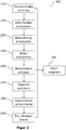
- the Figure 1 shows a system 100 according to the invention for detecting the components in a quantity of objects, in particular waste, garbage and / or valuable materials, which is distributed over an area, in particular in a vehicle for garbage collection.
- the system 100 has an RGB camera (first optical recording device) 110, a multispectral camera (second optical recording device) 120, a 3D camera (third optical recording device) 130 and a data processing unit 140. These three optical recording devices 110, 120, 130 and the data processing unit 140 are required for the functioning of the system 100.
- the in Figure 1 The system 100 shown furthermore has, as optional features, a lighting unit 150, a GPS unit (geographical position determination unit) 160, a thermal camera 170, an alarm unit 180 and a data memory 190.
- the RGB camera 110 is preferably a conventional digital camera with an image resolution of 5 MP or more and a fixed focal length that is suitable for capturing the relevant area in the hold of a refuse collection vehicle.
- the multispectral camera 120 is set up for this purpose a series of images at different wavelengths between visible light and Record near-infrared light.
- the 3D camera 130 is preferably a stereo camera or a time-of-flight camera.
- the stereo camera preferably consists of the RGB camera 110 and a further RGB camera which is identical to it and which is fixedly positioned relative to the RGB camera 110 in order to enable a 3D reconstruction.
- the three optical recording devices 110, 120, 130 are permanently installed in the vehicle and aligned relative to a common reference point so that all images can be superimposed directly.
- the data processing unit 140 has a suitable computer which is set up with software for evaluating the recorded images using a neural network.
- the neural network is trained to recognize a number of different object types in the recorded images and thus to detect the components of the existing set of objects.
- the data processing unit 140 can also be configured to detect the quantity (or size) of each object.
- the result i.e. a list of recognized object types and possibly the quantities of objects, is stored in the memory in the data processing unit 140 and / or in an external memory 190.
- the external memory may be attached separately in the vehicle or in a control center. In the latter case, the data is transmitted via a secure mobile data connection.
- the data processing unit 140 can also be installed in the control center, where the evaluation of the recorded data is then carried out. In the latter case, the image data are preferably transmitted to the control center by means of mobile data communication.
- the lighting unit 150 is fixedly mounted in the vehicle and aligned in such a way that the area with the objects to be detected is illuminated well and evenly.
- the spectral composition of the delivered Light is adapted in particular to the corresponding requirements of the multispectral camera 120.
- the GPS unit 160 determines the corresponding geographical position of the vehicle as well as the date and time for each process. These data are stored together with the images from the three optical recording devices 110, 120, 130 and the analysis result of the data processing unit 140, so that the recorded components can be assigned to a geographical position and, if applicable, the date and time.
- the thermal camera 170 is also permanently installed in the vehicle and is designed to determine a heat distribution in the set of objects to be analyzed, for example as a color image in which each color tone corresponds to a specific temperature.
- the determined temperature distribution may be included in the analysis carried out by the data processing unit 140. If a temperature above a predetermined threshold value is detected, the alarm unit 180 can be triggered in order to notify the driver of the vehicle of a dangerous situation so that he can immediately take appropriate safety measures.
- FIG. 2 shows a method 200 in accordance with an embodiment of the present invention.
- the method 200 begins at 210 by placing the contents of a garbage can in the collection vehicle and determining the geographic position of the vehicle at 220.
- the quantity of objects distributed on the area provided for this purpose in the vehicle is now illuminated at 230 by switching on the lighting unit 150.
- images are recorded by each of the optical recording devices 110, 120, 130 and optionally by the thermal camera 170.
- the RGB photo captured by the first optical capture device 110 which is captured by the Spectral images recorded by the second optical recording device 120 and the 3D image recorded by the third optical recording device 130 are then analyzed at 250 by the data processing unit 140 using a neural network so as to detect the constituents in the scanned set of objects.
- a dangerous object such as a chemical product or a burning object
- an alarm is issued at 260 to alert the driver of the vehicle.
- the result of the acquisition process possibly together with the position, date and time, is saved.
- the lighting unit 150 is turned off and the quantity of objects is compressed at 280 in the vehicle.
- the collection continues at 290 by driving the vehicle to the next bin and repeating steps 210 to 280.
- the constituents of each emptied bin are consequently recorded and stored, so that detailed information about all the objects collected is available upon arrival at the processing plant and can be used to make processing optimally and safely.
Landscapes
- Engineering & Computer Science (AREA)
- Physics & Mathematics (AREA)
- General Physics & Mathematics (AREA)
- Multimedia (AREA)
- Theoretical Computer Science (AREA)
- Mechanical Engineering (AREA)
- Spectroscopy & Molecular Physics (AREA)
- Life Sciences & Earth Sciences (AREA)
- Health & Medical Sciences (AREA)
- Chemical & Material Sciences (AREA)
- Analytical Chemistry (AREA)
- Biochemistry (AREA)
- General Health & Medical Sciences (AREA)
- Immunology (AREA)
- Pathology (AREA)
- Investigating Or Analysing Materials By Optical Means (AREA)
- Length Measuring Devices By Optical Means (AREA)
- Sorting Of Articles (AREA)
Description
- Die Erfindung betrifft das Gebiet der Erfassung von Bestandteilen in einer Menge von Gegenständen, insbesondere ein System und ein Verfahren zum Erfassen der Bestandteile in einer Menge von Gegenständen, insbesondere Abfällen, Müll und/oder Wertstoffen, die auf eine Fläche, insbesondere in einem Fahrzeug zur Müllabfuhr, verteilt ist. Die Erfindung betrifft des Weiteren ein Fahrzeug zur Müllabfuhr.
- Müll, Abfall und verschiedene Wertstoffe werden üblicherweise in regelmäßigen Abständen von speziellen Fahrzeugen eingesammelt und zur Weiterverarbeitung, z.B. Verbrennung oder Recycling, in einer dazu eingerichteten Behandlungsanlage transportiert. In der Behandlungsanlage werden die eingesammelten Güter analysiert und sortiert, um eine gesetzeskonforme und nachhaltige Behandlung zu ermöglichen. Um eine Vermischung unterschiedlicher Abfallarten möglichst gering zu halten und den daraus folgenden erhöhten Sortieraufwand bei der Behandlung zu minimieren, findet vor der Einsammlung eine Grobsortierung statt, indem Abfallbesitzer verpflichtet werden, die die unterschiedlichen Abfallfraktionen in spezifische Abfalltonnen zu entsorgen. Daher werden separate Tonnen für verschiedene Kategorien, z.B. Restmüll, Kunststoffe, Dosen, Biomüll und Glas vor Wohnhäusern und Firmengebäuden bereitgestellt. Bei der Abfallentsorgung durch die Abfallbesitzer wird aber nicht geprüft, ob sie diese Trennpflicht erfüllen bzw. ob diese Grobsortierung bei allen Abgabestellen korrekt durchgeführt wird. Mit anderen Worten werden die Inhalte der Tonnen der relevanten Kategorie nicht kontrolliert, sondern einfach in das Fahrzeug geladen und zur Behandlungsanlage transportiert. Diese Vorgehensweise ist mit mehreren Nachteilen verbunden. Erstens kann die fehlende Kontrolle der Tonneninhalte und Abfallzusammensetzung zu gefährlichen Situationen, z.B. Feuern im Fahrzeug führen. Zweitens muss eine gründliche und aufwendige Prüfung immer in der Behandlungsanlage durchgeführt werden.
-
EP 3 208 753 A1 beschreibt ein Abfallmanagement-System zur Fernprüfung. Das System kann einen optischen Sensor aufweisen, der an Bord des Servicefahrzeugs montiert werden kann und konfiguriert ist, um mit dem Abfall verbundene Bilddaten zu erfassen. - Sathish Paulraj Gundupalli et al: "Multi-material classification of dry recyclables from municipal solid waste based on thermal imaging" offenbart ein Wärmebildsystem zur Klassifizierung von nützlichen Wertstoffen aus einer simulierten Probe von Siedlungsabfällen.
- Dr Tuomas et al: "ZenRobotics Recycler - Robotic Sorting using Machine Learning" offenbart ein System, das Bau- und Abbruchabfälle sortiert, indem es wertvolle Objekte mit Roboterhänden von einem Förderband aufnimmt und so eine nützliche Reinheit von Holz, Stein und Metall erreicht, ohne auf menschliche Sortierer zurückgreifen zu müssen. Maschinelles Lernen wird verwendet, um einige der Hauptproblemen zu lösen, wie z.B. das Erkennen von Materialien und das Greifen von unregelmäßigen Objekten aus einem Abfallstrom auf einer Förderband.
- Der vorliegenden Erfindung liegt die Aufgabe zugrunde, verbesserte Techniken bereitzustellen, welche die oben beschriebenen und weitere Probleme überwinden können.
- Diese Aufgabe wird gelöst durch die Gegenstände der unabhängigen Patentansprüche. Vorteilhafte Ausführungsformen der vorliegenden Erfindung sind in den abhängigen Ansprüchen beschrieben.
- Gemäß einem ersten Aspekt der Erfindung wird ein System beschrieben zum
- Erfassen der Bestandteile in einer Menge von Gegenständen, welche Abfälle, Müll und/oder Wertstoffe aufweisen, die auf eine Fläche in einem Pressmüllfahrzeug verteilt ist. Das System aufweisend:
- (a) eine erste optische Aufnahmevorrichtung, die zum Aufnehmen eines 2D-Farbbildes der Menge von Gegenständen eingerichtet ist;
- (b) eine zweite optische Aufnahmevorrichtung, die zum Aufnehmen einer Mehrzahl von 2D-Spektralbildern der Menge von Gegenständen eingerichtet ist, wobei jedes 2D-Spektralbild einer vorbestimmten jeweiligen Wellenlänge entspricht;
- (c) eine dritte optische Aufnahmevorrichtung, die zum Aufnehmen eines 3D-Bildes der Menge von Gegenständen eingerichtet ist;
- (d) eine Beleuchtungseinheit, die zum Beleuchten der Menge von Gegenständen eingerichtet ist; und
- (e) eine Datenverarbeitungseinheit, die zum Erfassen der Bestandteile in der Menge von Gegenständen basierend auf dem 2D-Farbbild, der Mehrzahl von 2D-Spektralbildern und dem 3D-Bild und unter Verwendung eines neuronalen Netzwerks eingerichtet ist, wobei die Datenverarbeitungseinheit ferner eingerichtet ist anhand des neuronalen Netzwerks die Bestandteile der vorhandenen Menge von Gegenständen in den aufgenommenen Bildern zu erfassen.
- Das System ist zudem konfiguriert bei der Müllschütte eines Pressmüllfahrzeugs montiert zu werden, welche Umgebung vollkommen dunkel und sehr starker mechanischer Belastung ausgesetzt ist.
- Gemäß einem Ausführungsbeispiel der Erfindung liegt dem beschriebenen System die Erkenntnis zugrunde, dass eine intelligente Auswertung der optischen Eigenschaften der gerade nach dem Ausleeren einer Tonne auf einer Fläche im Fahrzeug vorhandenen Menge von Gegenständen eine effiziente und zuverlässige Erfassung der einzelnen Bestandteile dieser Menge erlaubt. Zum einen kann es somit sofort erkannt werden, wenn gefährliche Gegenstände in das Fahrzeug geladen werden. Zum anderen bestehen bei der Ankunft in der Behandlungsanlage detaillierte Kenntnisse über die eingesammelten Güter, so dass die weitere Sortierung und Verarbeitung gezielt gestaltet und angepasst werden kann.
- Gemäß einem Ausführungsbeispiel der Erfindung wird erstmals ein System (zum Erfassen einer Menge von Abfällen und Müll) beschrieben, welches nicht an einem Förderband innerhalb einer Anlage (z.B. einer Müllsortierungsanlage) betrieben wird, sondern in der "unwirtlichen" Umgebung eines Müllfahrzeugs montiert ist. Insbesondere ist das beschriebene System (zumindest teilweise) bei der Schütte eines Pressmüllfahrzeugs montiert. Diese Umgebung ist vollkommen dunkel und sehr starker mechanischer Belastung (insbesondere Rütteln und Schütteln) ausgesetzt, durch das fahrende Müllauto, durch die Pressvorgänge und auch durch herumfliegenden Müll. Aus diesem Grund sind die Herausforderungen an Beleuchtung, Elektronik und Verschmutzung bei dem vorliegenden System enorm hoch. Im Vergleich zu der vergleichsweise beschaulichen Messumgebung innerhalb einer Förderanlage erfordert die Messumgebung einer rüttelnden, dunklen, und schmutzigen Umgebung einer Müllschütte vollkommen andere technische Lösungen.
- Zudem werden in bekannten Förderanlagen meist homogene Gemische (z.B. nur Kunststoffe) untersucht. In einem Müllfahrzeug, welches sich z.B. im städtischen Betrieb befindet, sammeln sich jedoch Abfälle unterschiedlichster Arten. Neben der Beständigkeit gegen die extremen Bedingungen innerhalb eines fahrenden Müllfahrzeugs muss das beschriebene System zusätzlich in der Lage sein jegliche Abfallmischung, insbesondere Restmüll und/oder Biomüll aufweisend, erfassen und auch klassifizieren zu können. Gerade eine Restmüll-Mischung ist sehr viel komplexer in der Klassifizierung als z.B. eine reine Kunststoff-Fraktion.
- Gemäß einem weiteren Ausführungsbeispiel der Erfindung hat sich überraschenderweise gezeigt, dass es gerade die Kombination der drei voneinander verschiedenen optischen Messtechniken, nämlich i) 2D-Farbbild, ii) 2D-Spektralbild, und iii) 3D-Bild (also z.B. Stereo oder TOF) ist, welche es ermöglicht unter den oben beschriebenen mechanischen Extrembedingungen auf effiziente und zuverlässige Weise eine Klassifizierung einer vollkommen inhomogenen Abfallmischung zu erhalten. Hierbei kann gerade die Tiefeninformation des 3D (Stereo) Kamerasystems, z.B. für die Abgrenzung der Schütte im Fahrzeug vom tatsächlich zu klassifizierenden Abfall, sehr vorteilhaft sein.
- Die Auswertung mittels des neuronalen Netzwerkes ermöglicht es schließlich eine Datenverarbeitungseinheit auf diese hochkomplexe
- Klassifizierungstätigkeit "zu trainieren". Der Lernalgorithmus kann Standard neuronale Netze nutzen und damit einen vielseitigen Einsatz des Klassifikationssystems ermöglichen.
- In diesem Dokument bezeichnet "2D-Farbbild" insbesondere ein gewöhnliches digitales Foto, insbesondere mit einer Auflösung von 5MP oder mehr.
- In diesem Dokument bezeichnet "2D-Spektralbild" insbesondere ein Bild, das bei einer bestimmten Wellenlänge aufgenommen wurde, wobei die Wellenlänge im Bereich von sichtbarem Licht bis zum Nahinfrarotlicht liegen mag.
- In diesem Dokument bezeichnet "3D-Bild" insbesondere ein dreidimensionales Bild, das z.B. mit einer (aktiven oder passiven) Stereokamera oder mit einer Laufzeitkamera (TOF-Kamera) aufgenommen wurde.
- Erfindungsgemäß kann das beschriebene System insbesondere so verwendet werden, dass nach einem Ausladen der Inhalte einer Mülltonne in ein Müllabfuhrfahrzeug die erste, zweite und dritte optische Aufnahmevorrichtung betrieben werden und die dadurch entstandenen Bilddaten mittels der Datenverarbeitungseinheit unter Verwendung eines neuronalen Netzwerks ausgewertet werden, um die einzelnen Bestandteile zu erfassen. Erst danach werden die Güter komprimiert. Somit kann es bei jedem einzelnen Beladungsvorgang mit großer Genauigkeit erfasst werden, welche Bestandteile in der eingefüllten Menge von Gegenständen vorhanden sind.
- Gemäß einem Ausführungsbeispiel der Erfindung weist das Erfassen der Bestandteile in der Menge von Gegenständen ein Erfassen eines Gegenstandstyps für jeden Gegenstand auf.
- Es wird folglich für jeden einzelnen Gegenstand ein entsprechender Gegenstandstyp, zum Beispiel "Zeitung", "Aluminiumdose", "Batterie", "Plastikdose" usw. bestimmt. Das Ergebnis der Erfassung umfasst somit eine Liste von den Gegenstandstypen, die in der Menge von Gegenständen enthalten sind.
- Gemäß einem weiteren Ausführungsbeispiel der Erfindung weist das Erfassen der Bestandteile in der Menge von Gegenständen ein Erfassen einer Gegenstandsmenge für jeden Gegenstand auf.
- Es wird folglich für jeden einzelnen Gegenstand eine entsprechende Gegenstandmenge, zum Beispiel ein Volumen oder eine Masse bestimmt. Das Ergebnis der Erfassung umfasst somit eine Angabe der Menge von jedem Bestandteil.
- Die Beleuchtungseinheit ist insbesondere dazu eingerichtet, die zu erfassende Menge von Gegenständen kräftig und gleichmäßig zu beleuchten, um eine gute und reproduzierbare Beleuchtung für die optischen Aufnahmevorrichtungen bereitzustellen. Die Beleuchtungseinheit ist des Weiteren dazu eingerichtet, Licht mit einer spektralen Zusammensetzung auszustrahlen, die jede der vorbestimmten Wellenlängen der zweiten optischen Aufnahmevorrichtung beinhaltet.
- Gemäß einem weiteren Ausführungsbeispiel der Erfindung weist das System ferner eine Positionsbestimmungseinheit auf, die zum Bestimmen einer geografischen Position der Menge von Gegenständen und zum Speichern dieser geografischen Position zusammen mit dem 2D-Farbbild, der Mehrzahl von 2D-Spektralbildern und dem 3D-Bild eingerichtet ist.
- Die Positionsbestimmungseinheit mag insbesondere eine GPS-Einheit oder ähnliches aufweisen. Durch Kenntnis der geografischen Position kann es zum Beispiel festgestellt werden, bei welchen Wohnhäusern der Müll falsch vorsortiert wird oder gefährliche Gegenstände abgegeben werden, die anders entsorgt werden müssen.
- Gemäß einem weiteren Ausführungsbeispiel der Erfindung ist die Positionsbestimmungseinheit ferner zum Bestimmen eines Datums und einer Uhrzeit eingerichtet.
- Gemäß einem weiteren Ausführungsbeispiel der Erfindung sind die erste optische Aufnahmevorrichtung, die zweite optische Aufnahmevorrichtung und die dritte optische Aufnahmevorrichtung relativ zu einem vorbestimmten Referenzpunkt fest angeordnet.
- Dies ermöglicht insbesondere eine Überlagerung der jeweiligen Bilder und somit eine detaillierte Auswertung derselben.
- Gemäß einem weiteren Ausführungsbeispiel der Erfindung weist das System ferner eine Wärmekamera auf, die zum Bestimmen einer Temperaturverteilung in der Menge von Gegenständen eingerichtet ist.
- Die Temperaturverteilung mag auch zum Erfassen der Bestandteile herangezogen werden.
- Gemäß einem weiteren Ausführungsbeispiel der Erfindung weist das System ferner eine Alarmeinheit auf, die zum Abgeben eines Alarmsignals eingerichtet ist, wenn die Menge von Gegenständen eine Temperatur aufweist, welche einen vorbestimmten Temperaturschwellenwert überschreitet.
- Mit anderen Worten wird ein Alarmsignal abgegeben, wenn ein oder mehrere Gegenstände eine ausreichend hohe Temperatur haben. Somit können gefährliche Situationen, die zu brennenden Fahrzeugen führen können, vermieden werden.
- Gemäß einem weiteren Ausführungsbeispiel der Erfindung weist die dritte optische Aufnahmevorrichtung die erste optische Aufnahmevorrichtung, eine weitere optische Aufnahmevorrichtung und eine 3D-Datenverarbeitungseinheit auf, wobei die weitere optische Aufnahmevorrichtung identisch mit der ersten optischen Aufnahmevorrichtung und in einer relativ zu dieser vorbestimmten Position angebracht ist, wobei die 3D-Datenverarbeitungseinheit zum Erzeugen von 3D-Bilddaten basierend auf 2D-Bildern, die von der ersten optischen Aufnahmevorrichtung und der weiteren optischen Aufnahmevorrichtung aufgenommen wurden, eingerichtet ist.
- In diesem Ausführungsbeispiel besteht die dritte optische Aufnahmevorrichtung aus zwei identischen oder weitgehend ähnlichen 2D-Kameras, wobei die eine gleichzeitig die erste optische Aufnahmevorrichtung ist. Die beiden Kameras sind relativ zueinander fest angebracht und erlauben somit ein Erzeugen von 3D-Bilddaten durch die 3D-Datenverarbietungseinheit.
- Gemäß einem weiteren Ausführungsbeispiel der Erfindung ist die Datenverarbeitungseinheit in einer Zentrale angebracht, das System ferner aufweisend eine Datenkommunikationseinheit, die zum Übertragen von Daten, insbesondere dem 2D-Farbbild, der Mehrzahl von 2D-Spektralbildern und dem 3D-Bild von der ersten, zweiten und dritten Aufnahmevorrichtung an die Datenverarbeitungseinheit eingerichtet ist.
- In diesem Ausführungsbeispiel befindet die Datenverarbeitungseinheit sich in einer Zentrale und erhält die Bilddaten (und gegebenenfalls weitere Daten, wie z.B. GPS-Daten) mittels Datenübertragung durch die Datenkommunikationseinheit, z.B. mittels Mobilfunkübertragung, WLAN oder ähnliches.
- Gemäß einem zweiten Aspekt der Erfindung wird ein Fahrzeug zur Müllabfuhr beschrieben, das ein System gemäß dem ersten Aspekt oder einem der obigen Ausführungsformen aufweist.
- Gemäß einem dritten Aspekt der Erfindung wird ein Verfahren beschrieben zum Erfassen der Bestandteile in einer Menge von Gegenständen, welche Abfälle, Müll und/oder Wertstoffe aufweisen, die auf eine Fläche in einem Pressmüllfahrzeug, verteilt ist, das Verfahren aufweisend:
- (a) Beleuchten der Menge von Gegenständen;
- (b) Aufnehmen eines 2D-Farbbildes der Menge von Gegenständen;
- (c) Aufnehmen einer Mehrzahl von 2D-Spektralbildern der Menge von Gegenständen, wobei jedes 2D-Spektralbild einer vorbestimmten jeweiligen Wellenlänge entspricht;
- (d) Aufnehmen eines 3D-Bildes der Menge von Gegenständen; und
- (e) Erfassen der Bestandteile in der Menge von Gegenständen basierend auf dem 2D-Farbbild, der Mehrzahl von 2D-Spektralbildern und dem 3D-Bild und unter Verwendung eines neuronalen Netzwerks, wobei die Bestandteile der vorhandenen Menge von Gegenständen in den aufgenommenen Bildern anhand des neuronalen Netzwerks erfasst werden.
- Gemäß einem weiteren Ausführungsbeispiel ist zumindest eine der ersten optischen Aufnahmevorrichtung, der zweiten optischen Aufnahmevorrichtung, und der dritten optischen Aufnahmevorrichtung eingerichtet, um Bildserien aufzunehmen. Ferner kann das System eingerichtet sein (insbesondere mittels der Beleuchtungseinheit) eine dynamische Beleuchtung bereitzustellen.
- Um die Information unter den unwidrigen und variierenden Beleuchtungsbedingungen stabiler und robuster bereitstellen zu können, hat es sich in einem Ausführungsbeispiel als vorteilhaft herausgestellt, Bildserien aufzunehmen und über die Dynamik von Belichtungszeiten zu optimieren.
- Gemäß einem weiteren Ausführungsbeispiel ist das System (zumindest teilweise) mit der Spannungsversorgung des Müllfahrzeugs über eine Spitzenglättung und/oder eine Unterspannungsversorgung gekoppelt.
- Eine weitere Herausforderung ist der stabile Einbau des beschriebenen Systems im Müllfahrzeug. In einem Ausführungsbeispiel hat es sich als vorteilhaft herausgestellt, die Hardware des Systems mit der Spannungsversorgung des Müllfahrzeugs über eine Spitzenglättung und/oder Unterspannungsversorgung zu kombinieren. Zusätzlich kann eine Kombination von langsam anlaufender Beleuchtung (damit nicht zu viel Strom gezogen wird) und einer optimierten Kopplung mit der Steuerung eines Standard-Müllfahrzeugs durchaus vorteilhaft sein.
- Gemäß einem weiteren Ausführungsbeispiel weist das System auf: eine Projektionsvorrichtung zum Bereitstellen einer Lichtprojektion, insbesondere einer Laserprojektion, und eine Kalibriervorrichtung zum Durchführen einer Achsenkalibrierung mittels der Lichtprojektion. Hierdurch kann die Genauigkeit der Aufnahmevorrichtungen verbessert werden.
- Gemäß einem weiteren Ausführungsbeispiel sind die zweite Aufnahmevorrichtung (insbesondere ein Infrarot bzw. NIR Sensor) und die dritte Aufnahmevorrichtung (insbesondere eine RGB-Stereo-Kamera), insbesondere über eine Sensorfusion, gekoppelt.
- Gemäß einem weiteren Ausführungsbeispiel weist die Sensorfusion eine Kopplung der zweiten Aufnahmevorrichtung und der dritten Aufnahmevorrichtung über die (insbesondere automatische) Achsenkalibrierung mittels der Licht (insbesondere Laser, weiter insbesondere Laser-Punkt) Projektion auf.
- In einem exemplarischen Ausführungsbeispiel kann eine Sensoreinheit eine Sensorfusion von RGB-Stereo Kamera(s) und einem NIR (near infrared) Sensor über eine automatische Achsenkalibrierung über eine Laser-Punkt Projektion umfassen. Durch diese Laser-Punkt Projektion können auch die Daten von homogenen Flächen für einen Lernalgorithmus vorteilhaft verwendet werden.
- Gemäß einem weiteren Ausführungsbeispiel weist die Menge an Gegenständen eine inhomogene Mischung aus Abfällen und Müll, insbesondere Restmüll und/oder Biomüll beinhaltend, auf.
- Gemäß einem weiteren Ausführungsbeispiel weist das System ferner auf: eine Komprimier-Einheit, welche eingerichtet ist zum Komprimieren der erfassten Daten und zum Bereitstellen der komprimierten Daten an die Datenkommunikationseinheit.
- Gemäß einem exemplarischen Ausführungsbeispiel erfolgt eine Komprimierung der Daten auf einem im System enthaltenen Industrie-PC, damit die Übermittlung aus dem Fahrzeug über WLAN (falls vorhanden am jeweiligen Standort) oder LTE erfolgen kann.
-
-
Figur 1 zeigt ein System gemäß einer Ausführungsform der vorliegenden Erfindung. -
Figur 2 zeigt ein Verfahren gemäß einer Ausführungsform der vorliegenden Erfindung. - Die
Figur 1 zeigt ein erfindungsgemäßes System 100 zum Erfassen der Bestandteile in einer Menge von Gegenständen, insbesondere Abfällen, Müll und/oder Wertstoffen, die auf eine Fläche, insbesondere in einem Fahrzeug zur Müllabfuhr, verteilt ist. - Das System 100 weist eine RGB-Kamera (erste optische Aufnahmevorrichtung) 110, eine Multispektralkamera (zweite optische Aufnahmevorrichtung) 120, eine 3D-Kamera (dritte optische Aufnahmevorrichtung) 130 und eine Datenverarbeitungseinheit 140 auf. Diese drei optische Aufnahmevorrichtungen 110, 120, 130 und die Datenverarbeitungseinheit 140 sind erforderlich für die Funktion des Systems 100. Das in
Figur 1 gezeigte System 100 weist des Weiteren als optionale Merkmale eine Beleuchtungseinheit 150, eine GPS-Einheit (geografische Positionsbestimmungseinheit) 160, eine Wärmekamera 170, eine Alarmeinheit 180 und einen Datenspeicher 190 auf. - Die RGB-Kamera 110 ist vorzugsweise eine gewöhnliche Digitalkamera mit einer Bildauflösung von 5 MP oder mehr und einer festen Brennweite, die zum Ablichten des relevanten Bereichs in dem Laderaum eines Müllabfuhrfahrzeugs geeignet ist. Die Multispektralkamera 120 ist dazu eingerichtet eine Reihe von Bildern bei verschiedenen Wellenlängen zwischen sichtbarem Licht und Nahinfrarotlicht aufzunehmen. Die 3D-Kamera 130 ist vorzugsweise eine Stereokamera oder eine Laufzeitkamera. Im ersten Falle besteht die Stereokamera vorzugsweise aus der RGB-Kamera 110 und eine weitere, mit dieser identische RGB-Kamera, die relativ zu der RGB-Kamera 110 fest positioniert ist, um eine 3D-Rekonstruktion zu ermöglichen. Die drei optischen Aufnahmevorrichtungen 110, 120, 130 sind im Fahrzeug fest installiert und relativ zu einem gemeinsamen Referenzpunkt ausgerichtet, damit alle Bilder unmittelbar überlagert werden können.
- Die Datenverarbeitungseinheit 140 weist einen geeigneten Computer auf, der mit Software zum Auswerten der aufgenommenen Bilder unter Verwendung eines neuronalen Netzwerks eingerichtet ist. Das neuronale Netzwerk ist dazu trainiert, eine Reihe von verschiedenen Gegenstandstypen in den aufgenommenen Bildern zu erkennen und somit zum Erfassen der Bestandteile der vorhandenen Menge von Gegenständen. Zusätzlich zum Erfassen der Gegenstandstypen kann die Datenverarbeitungseinheit 140 auch dazu eingerichtet sein, die vorhandene Menge (oder Größe) von jedem Gegenstand zu erfassen. Das Ergebnis, d.h. eine Liste von erkannten Gegenstandstypen und gegebenenfalls Gegenstandsmengen wird im Speicher in der Datenverarbeitungseinheit 140 und/oder in einem externen Speicher 190 gespeichert. Der externe Speicher mag separat im Fahrzeug oder in einer Zentrale angebracht sein. Im letzteren Falle werden die Daten über eine gesicherte mobile Datenverbindung übertragen. Die Datenverarbeitungseinheit 140 kann ebenso in der Zentrale angebracht sein, wo dann die Auswertung der erfassten Daten ausgeführt wird. Im letzteren Falle werden die Bilddaten vorzugsweise mittels mobiler Datenkommunikation an die Zentrale übertragen.
- Die Beleuchtungseinheit 150 ist fest im Fahrzeug angebracht und so ausgerichtet, dass die Fläche mit den zu erfassenden Gegenständen gut und gleichmäßig belichtet wird. Die spektrale Zusammensetzung des abgegebenen Lichts ist insbesondere an die entsprechenden Erfordernisse der Multispektralkamera 120 angepasst.
- Die GPS-Einheit 160 bestimmt bei jedem Vorgang die entsprechende geografische Position des Fahrzeugs sowie Datum und Uhrzeit. Diese Daten werden zusammen mit den Bildern von den drei optischen Aufnahmevorrichtungen 110, 120, 130 und dem Analyseergebnis der Datenverarbeitungseinheit 140 gespeichert, so dass die erfassten Bestandteile einer geografischen Position und gegebenenfalls Datum und Uhrzeit zugeordnet werden können.
- Die Wärmekamera 170 ist auch fest im Fahrzeug installiert und ist dazu eingerichtet, eine Wärmeverteilung in der zu analysierenden Menge von Gegenständen zu bestimmen, zum Beispiel als ein Farbbild, in welchem jeder Farbton einer bestimmten Temperatur entspricht. Die bestimmte Temperaturverteilung mag in der von der Datenverarbeitungseinheit 140 durchgeführten Analyse mit einfließen. Falls eine Temperatur über einen vorbestimmten Schwellwert erkannt wird, kann die Alarmeinheit 180 ausgelöst werden, um den Fahrer des Fahrzeugs auf eine gefährliche Situation hinzuweisen, damit dieser sofort entsprechende Sicherheitsmaßnahmen einsetzen kann.
-
Figur 2 zeigt ein Verfahren 200 gemäß einer Ausführungsform der vorliegenden Erfindung. Das Verfahren 200 beginnt bei 210, indem die Inhalte einer Mülltonne in das Abfuhrfahrzeug eingefüllt werden und die geografische Position des Fahrzeugs bei 220 bestimmt wird. Die auf der dazu vorgesehenen Fläche im Fahrzeug verteilte Menge von Gegenständen wird nun bei 230 durch Einschaltung der Beleuchtungseinheit 150 beleuchtet. Dann werden bei 240 Bilder von jeder der optischen Aufnahmevorrichtungen 110, 120, 130 und gegebenenfalls von der Wärmekamera 170 aufgenommen. Das von der ersten optischen Aufnahmevorrichtung 110 aufgenommene RGB-Foto, die von der zweiten optischen Aufnahmevorrichtung 120 aufgenommenen Spektralbilder und das von der dritten optischen Aufnahmevorrichtung 130 aufgenommene 3D-Bild werden dann bei 250 von der Datenverarbeitungseinheit 140 unter Verwendung eines neuronalen Netzwerks analysiert, um so die Bestandteile in der abgelichteten Menge von Gegenständen zu erfassen. Wird ein gefährlicher Gegenstand, wie zum Beispiel ein chemisches Produkt oder ein brennender Gegenstand erkannt, wird bei 260 ein Alarm abgegeben, um den Fahrer des Fahrzeugs zu alarmieren. Bei 270 wird das Ergebnis des Erfassungsvorgangs, gegebenenfalls zusammen mit Position, Datum und Uhrzeit, gespeichert. Dann wird die Beleuchtungseinheit 150 ausgeschaltet und die Menge von Gegenständen wird bei 280 im Fahrzeug komprimiert. Die Abholung wird bei 290 fortgesetzt, indem das Fahrzeug zur nächsten Tonne fährt und die Schritte 210 bis 280 wiederholt werden. - Mit dem Verfahren 200 werden folglich die Bestandteile jeder geleerten Tonne erfasst und gespeichert, so dass detaillierte Informationen über die gesamten eingesammelten Gegenstände beim Ankunft in der Verarbeitungsanlage vorliegen und genutzt werden können, um die Verarbeitung optimal und sicher zu gestalten.
Claims (14)
- System (100) zum Erfassen der Bestandteile in einer Menge von Gegenständen, welche Abfälle, Müll und/oder Wertstoffe aufweisen, die auf eine Fläche in einem Pressmüllfahrzeug verteilt ist, das System aufweisend:eine erste optische Aufnahmevorrichtung (110), die zum Aufnehmen eines 2D-Farbbildes der Menge von Gegenständen eingerichtet ist;eine zweite optische Aufnahmevorrichtung (120), die zum Aufnehmen einer Mehrzahl von 2D-Spektralbildern der Menge von Gegenständen eingerichtet ist, wobei jedes 2D-Spektralbild einer vorbestimmten jeweiligen Wellenlänge entspricht;eine dritte optische Aufnahmevorrichtung (130), die zum Aufnehmen eines 3D-Bildes der Menge von Gegenständen eingerichtet ist;eine Beleuchtungseinheit (150), die zum Beleuchten der Menge von Gegenständen eingerichtet ist; undeine Datenverarbeitungseinheit (140), die zum Erfassen der Bestandteile in der Menge von Gegenständen basierend auf dem 2D-Farbbild, der Mehrzahl von 2D-Spektralbildern und dem 3D-Bild und unter Verwendung eines neuronalen Netzwerks eingerichtet ist, wobei die Datenverarbeitungseinheit (140) ferner eingerichtet ist anhand des neuronalen Netzwerks die Bestandteile der vorhandenen Menge von Gegenständen in den aufgenommenen Bildern zu erfassen;wobei das System konfiguriert ist bei der Müllschütte eines Pressmüllfahrzeugs montiert zu werden, welche Umgebung vollkommen dunkel und sehr starker mechanischer Belastung ausgesetzt ist.
- Das System gemäß dem vorhergehenden Anspruch, wobei das Erfassen der Bestandteile in der Menge von Gegenständen ein Erfassen eines Gegenstandstyps für jeden Gegenstand aufweist.
- Das System gemäß einem der vorhergehenden Ansprüche, wobei das Erfassen der Bestandteile in der Menge von Gegenständen ein Erfassen einer Gegenstandsmenge für jeden Gegenstand aufweist.
- Das System gemäß einem der vorhergehenden Ansprüche, ferner aufweisend eine Positionsbestimmungseinheit (160), die zum Bestimmen einer geografischen Position der Menge von Gegenständen und zum Speichern dieser geografischen Position zusammen mit dem 2D-Farbbild, der Mehrzahl von 2D-Spektralbildern und dem 3D-Bild eingerichtet ist.
- Das System gemäß dem vorhergehenden Anspruch, wobei die Positionsbestimmungseinheit ferner zum Bestimmen eines Datums und einer Uhrzeit eingerichtet ist.
- Das System gemäß einem der vorhergehenden Ansprüche, wobei die erste optische Aufnahmevorrichtung, die zweite optische Aufnahmevorrichtung und die dritte optische Aufnahmevorrichtung relativ zu einem vorbestimmten Referenzpunkt fest angeordnet sind.
- Das System gemäß einem der vorhergehenden Ansprüche, ferner aufweisend eine Wärmekamera (170), die zum Bestimmen einer Temperaturverteilung in der Menge von Gegenständen eingerichtet ist.
- Das System gemäß dem vorhergehenden Anspruch, ferner aufweisend eine Alarmeinheit (180), die zum Abgeben eines Alarmsignals eingerichtet ist, wenn die Menge von Gegenständen eine Temperatur aufweist, welche einen vorbestimmten Temperaturschwellenwert überschreitet.
- Das System gemäß einem der vorhergehenden Ansprüche, wobei die dritte optische Aufnahmevorrichtung die erste optische Aufnahmevorrichtung, eine weitere optische Aufnahmevorrichtung und eine 3D-Datenverarbeitungseinheit aufweist, wobei die weitere optische Aufnahmevorrichtung identisch mit der ersten optischen Aufnahmevorrichtung und in einer relativ zu dieser vorbestimmten Position angebracht ist, wobei die 3D-Datenverarbeitungseinheit zum Erzeugen von 3D-Bilddaten basierend auf 2D-Bildern, die von der ersten optischen Aufnahmevorrichtung und der weiteren optischen Aufnahmevorrichtung aufgenommen wurden, eingerichtet ist.
- Das System gemäß einem der vorhergehenden Ansprüche, wobei die Datenverarbeitungseinheit in einer Zentrale angebracht ist, das System ferner aufweisend eine Datenkommunikationseinheit, die zum Übertragen von Daten, insbesondere dem 2D-Farbbild, der Mehrzahl von 2D-Spektralbildern und dem 3D-Bild von der ersten, zweiten und dritten Aufnahmevorrichtung an die Datenverarbeitungseinheit eingerichtet ist.
- Das System gemäß einem der vorhergehenden Ansprüche, ferner aufweisend:eine Projektionsvorrichtung zum Bereitstellen einer Lichtprojektion, insbesondere einer Laserprojektion, undeine Kalibriervorrichtung zum Durchführen einer Achsenkalibrierung mittels der Lichtprojektion.
- Fahrzeug zur Müllabfuhr, das Fahrzeug aufweisend ein System gemäß einem der vorhergehenden Ansprüche,wobei das Fahrzeug ein Pressmüllfahrzeug mit einer Schütte ist, undwobei das System bei der Schütte montiert ist.
- Das Fahrzeug gemäß Anspruch 12,
wobei das System zumindest teilweise mit der Spannungsversorgung des Müllfahrzeugs über eine Spitzenglättung und/oder eine Unterspannungsversorgung gekoppelt ist. - Verfahren zum Erfassen der Bestandteile in einer Menge von Gegenständen, welche Abfälle, Müll und/oder Wertstoffe aufweisen, die auf eine Fläche in einem Pressmüllfahrzeug verteilt ist, das Verfahren aufweisend:Beleuchten der Menge von Gegenständen;Aufnehmen eines 2D-Farbbildes der Menge von Gegenständen;Aufnehmen einer Mehrzahl von 2D-Spektralbildern der Menge von Gegenständen, wobei jedes 2D-Spektralbild einer vorbestimmten jeweiligen Wellenlänge entspricht;Aufnehmen eines 3D-Bildes der Menge von Gegenständen; undErfassen der Bestandteile in der Menge von Gegenständen basierend auf dem 2D-Farbbild, der Mehrzahl von 2D-Spektralbildern und dem 3D-Bild und unter Verwendung eines neuronalen Netzwerks, wobei die Bestandteile der vorhandenen Menge von Gegenständen in den aufgenommenen Bildern anhand des neuronalen Netzwerks erfasst werden.
Priority Applications (1)
| Application Number | Priority Date | Filing Date | Title |
|---|---|---|---|
| PL19167744T PL3553698T3 (pl) | 2018-04-09 | 2019-04-08 | Wykrywanie składników w masie przedmiotów, zwłaszcza odpadów, śmieci i/lub surowców wtórnych |
Applications Claiming Priority (1)
| Application Number | Priority Date | Filing Date | Title |
|---|---|---|---|
| ATA50289/2018A AT521101B1 (de) | 2018-04-09 | 2018-04-09 | Erfassung der Bestandteile in einer Menge von Gegenständen, insbesondere Abfällen, Müll und/oder Wertstoffen |
Publications (2)
| Publication Number | Publication Date |
|---|---|
| EP3553698A1 EP3553698A1 (de) | 2019-10-16 |
| EP3553698B1 true EP3553698B1 (de) | 2021-10-27 |
Family
ID=66102451
Family Applications (1)
| Application Number | Title | Priority Date | Filing Date |
|---|---|---|---|
| EP19167744.2A Active EP3553698B1 (de) | 2018-04-09 | 2019-04-08 | Erfassung der bestandteile in einer menge von gegenständen, insbesondere abfällen, müll und/oder wertstoffen |
Country Status (4)
| Country | Link |
|---|---|
| EP (1) | EP3553698B1 (de) |
| AT (1) | AT521101B1 (de) |
| ES (1) | ES2905109T3 (de) |
| PL (1) | PL3553698T3 (de) |
Families Citing this family (3)
| Publication number | Priority date | Publication date | Assignee | Title |
|---|---|---|---|---|
| US12378068B2 (en) * | 2021-07-08 | 2025-08-05 | The Heil Co. | Refuse collection with auger and contamination detection panel |
| DK4181086T3 (da) | 2021-11-16 | 2024-10-07 | C Trace Gmbh | Affaldsbortskaffelsessystem og fremgangsmåde til detektering af forurenende stoffer i affaldsbeholdere |
| DE102023125252A1 (de) * | 2023-09-18 | 2025-03-20 | zebrafant.ai GmbH | Abfallerkennungssystem und computerimplementiertes Verfahren zum Bestimmen einer Eigenschaft von Abfall in einem Abfallbehälter |
Citations (1)
| Publication number | Priority date | Publication date | Assignee | Title |
|---|---|---|---|---|
| EP3208753A1 (de) * | 2016-02-20 | 2017-08-23 | Rubicon Global Holdings, LLC | Abfallmanagementsystem zur fernprüfung |
Family Cites Families (9)
| Publication number | Priority date | Publication date | Assignee | Title |
|---|---|---|---|---|
| CA2171851A1 (en) * | 1993-09-16 | 1995-03-23 | Herbert Furumoto | Device for controlling a deinked cellulose production plant with state analysers constituted of neural networks for the waste paper suspension |
| DE19543134A1 (de) * | 1995-11-18 | 1997-05-22 | Dietrich Dr Wienke | Verfahren und Vorrichtung zur getrennten Erfassung von Wertstoffen - insbesondere von Kunststoffverpackungen - in Form dezentral aufstellbarer sensorbetriebener intelligenter Container |
| JP2002267599A (ja) * | 2001-03-07 | 2002-09-18 | Mitsubishi Heavy Ind Ltd | プラスチックの材質識別システムおよびプラスチックの材質識別・分別システム |
| ES2330819B1 (es) * | 2007-08-30 | 2010-09-24 | Tt Ambiental Gestio I Serveis, S.L. | Sistema de gestion integral de recogida de residuos urbanos y de estado fisico del mobiliario y espacio urbano en una zona urbana. |
| JP2010094634A (ja) * | 2008-10-17 | 2010-04-30 | Canon Inc | プラスチックの分別装置および分別方法 |
| WO2014179667A2 (en) * | 2013-05-03 | 2014-11-06 | Ecowastehub Corp. | Solid waste identification & segregation system |
| FR3036107B1 (fr) * | 2015-05-11 | 2020-02-14 | Paprec Group | Vehicule de collecte de dechets |
| CN205596583U (zh) * | 2016-05-11 | 2016-09-28 | 安徽喜洋洋农业科技有限公司 | 一种新型智能测土配方施肥装置 |
| DE102016109999A1 (de) * | 2016-05-31 | 2017-11-30 | Mtm Plastics Gmbh | Verfahren und Vorrichtung zur Analyse inhomogener Schüttgüter |
-
2018
- 2018-04-09 AT ATA50289/2018A patent/AT521101B1/de not_active IP Right Cessation
-
2019
- 2019-04-08 ES ES19167744T patent/ES2905109T3/es active Active
- 2019-04-08 EP EP19167744.2A patent/EP3553698B1/de active Active
- 2019-04-08 PL PL19167744T patent/PL3553698T3/pl unknown
Patent Citations (1)
| Publication number | Priority date | Publication date | Assignee | Title |
|---|---|---|---|---|
| EP3208753A1 (de) * | 2016-02-20 | 2017-08-23 | Rubicon Global Holdings, LLC | Abfallmanagementsystem zur fernprüfung |
Also Published As
| Publication number | Publication date |
|---|---|
| AT521101A1 (de) | 2019-10-15 |
| ES2905109T3 (es) | 2022-04-07 |
| EP3553698A1 (de) | 2019-10-16 |
| PL3553698T3 (pl) | 2022-02-28 |
| AT521101B1 (de) | 2020-02-15 |
Similar Documents
| Publication | Publication Date | Title |
|---|---|---|
| EP3553698B1 (de) | Erfassung der bestandteile in einer menge von gegenständen, insbesondere abfällen, müll und/oder wertstoffen | |
| Palmieri et al. | Recycling-oriented characterization of plastic frames and printed circuit boards from mobile phones by electronic and chemical imaging | |
| DE102011088393B4 (de) | Bestimmen einer Gesamtzahl an Personen in einem IR-Bild, das mittels eines IR-Bilderzeugungssystems gewonnen wird | |
| DE4129754C2 (de) | Verfahren zur Gewinnung sortenreiner Kunststofffraktionen | |
| EP0795919B1 (de) | Verfahren zum Sortieren von Elektronikschrott, wie beispielsweise Altbatterien und/oder Altakkumulatoren, sowie Vorrichtung zur Durchführung des Verfahrens | |
| EP0439674A2 (de) | Vorrichtung zum Sortieren von Abfällen | |
| DE4305006A1 (de) | Verfahren zum automatischen Sortieren von Abfallmaterial und Verfahren zur Spektralanalyse von Stoffen sowie Einrichtungen zur Durchführung der Verfahren | |
| EP3494385B1 (de) | Vorrichtung und verfahren zur legierungsanalyse von schrottfragmenten aus metall | |
| EP4181086B1 (de) | Abfallentsorgungssystem und verfahren zur störstoffdetektion in abfallbehältern | |
| EP3465151B1 (de) | Verfahren und vorrichtung zur analyse inhomogener schüttgüter | |
| DD152870A1 (de) | Verfahren und vorrichtung zum klassieren in bewegung befindlichen stueckgutes | |
| WO1993019999A1 (de) | Verfahren und vorrichtung zur untersuchung von müll nach metallbestandteilen | |
| EP1421999A2 (de) | Verfahren zum Identifizieren, Klassifizieren und Sortieren von Gegenständen, Objekten und Materialien, sowie ein Erkennungssystem zur Durchführung dieses Verfahrens | |
| DE3215067A1 (de) | Automatische pruefvorrichtung zum nachweis von fremdkoerpern | |
| DE4033501A1 (de) | Sammel- und transportsystem fuer muell, insbesondere fuer wertstoffe aus hausmuell | |
| CN116967155A (zh) | 一种建筑废弃物现场智能分拣方法 | |
| EP0761311B1 (de) | Verfahren und Vorrichtung zum Identifizieren und Sortieren gebrauchter Gerätebatterien zur Verwertung | |
| DE19543134A1 (de) | Verfahren und Vorrichtung zur getrennten Erfassung von Wertstoffen - insbesondere von Kunststoffverpackungen - in Form dezentral aufstellbarer sensorbetriebener intelligenter Container | |
| EP1533045B1 (de) | Verfahren und Vorrichtung zur optimierten Sortierung von Altpapier und Altkarton | |
| EP3322983B1 (de) | Verfahren zur aufbereitung von ersatzbrennstoff sowie ein verfahren zur anschliessenden analyse des ersatzbrennstoffs | |
| EP0557738B1 (de) | Verfahren und Vorrichtung zur Unterscheidung von Kunststoffteilen sowie Verwendung des Verfahrens zur Aussonderung wiederverwertbarer Kunststoffteile aus Industrie- und/oder Hausmüll | |
| KR102914790B1 (ko) | Ai 기반 스마트 계근대 시스템 | |
| DE102023107571B4 (de) | Verfahren zur Beurteilung eines Einsatzes eines Schüttguts innerhalb eines Prozesses | |
| EP0922505B1 (de) | Verfahren und Vorrichtung zur automatischen und materialspezifischen Trennung von Telefonkarten | |
| DE102023106456A1 (de) | Abfallsammelfahrzeug sowie Verfahren zum Sammeln und Trennen von Abfall |
Legal Events
| Date | Code | Title | Description |
|---|---|---|---|
| PUAI | Public reference made under article 153(3) epc to a published international application that has entered the european phase |
Free format text: ORIGINAL CODE: 0009012 |
|
| STAA | Information on the status of an ep patent application or granted ep patent |
Free format text: STATUS: THE APPLICATION HAS BEEN PUBLISHED |
|
| AK | Designated contracting states |
Kind code of ref document: A1 Designated state(s): AL AT BE BG CH CY CZ DE DK EE ES FI FR GB GR HR HU IE IS IT LI LT LU LV MC MK MT NL NO PL PT RO RS SE SI SK SM TR |
|
| AX | Request for extension of the european patent |
Extension state: BA ME |
|
| STAA | Information on the status of an ep patent application or granted ep patent |
Free format text: STATUS: REQUEST FOR EXAMINATION WAS MADE |
|
| 17P | Request for examination filed |
Effective date: 20200406 |
|
| RBV | Designated contracting states (corrected) |
Designated state(s): AL AT BE BG CH CY CZ DE DK EE ES FI FR GB GR HR HU IE IS IT LI LT LU LV MC MK MT NL NO PL PT RO RS SE SI SK SM TR |
|
| STAA | Information on the status of an ep patent application or granted ep patent |
Free format text: STATUS: EXAMINATION IS IN PROGRESS |
|
| 17Q | First examination report despatched |
Effective date: 20200626 |
|
| GRAP | Despatch of communication of intention to grant a patent |
Free format text: ORIGINAL CODE: EPIDOSNIGR1 |
|
| STAA | Information on the status of an ep patent application or granted ep patent |
Free format text: STATUS: GRANT OF PATENT IS INTENDED |
|
| INTG | Intention to grant announced |
Effective date: 20210610 |
|
| GRAS | Grant fee paid |
Free format text: ORIGINAL CODE: EPIDOSNIGR3 |
|
| GRAA | (expected) grant |
Free format text: ORIGINAL CODE: 0009210 |
|
| STAA | Information on the status of an ep patent application or granted ep patent |
Free format text: STATUS: THE PATENT HAS BEEN GRANTED |
|
| AK | Designated contracting states |
Kind code of ref document: B1 Designated state(s): AL AT BE BG CH CY CZ DE DK EE ES FI FR GB GR HR HU IE IS IT LI LT LU LV MC MK MT NL NO PL PT RO RS SE SI SK SM TR |
|
| REG | Reference to a national code |
Ref country code: GB Ref legal event code: FG4D Free format text: NOT ENGLISH |
|
| REG | Reference to a national code |
Ref country code: CH Ref legal event code: EP |
|
| REG | Reference to a national code |
Ref country code: DE Ref legal event code: R096 Ref document number: 502019002584 Country of ref document: DE |
|
| REG | Reference to a national code |
Ref country code: AT Ref legal event code: REF Ref document number: 1442470 Country of ref document: AT Kind code of ref document: T Effective date: 20211115 |
|
| REG | Reference to a national code |
Ref country code: IE Ref legal event code: FG4D Free format text: LANGUAGE OF EP DOCUMENT: GERMAN |
|
| REG | Reference to a national code |
Ref country code: DE Ref legal event code: R079 Ref document number: 502019002584 Country of ref document: DE Free format text: PREVIOUS MAIN CLASS: G06K0009000000 Ipc: G06V0010000000 |
|
| REG | Reference to a national code |
Ref country code: LT Ref legal event code: MG9D |
|
| REG | Reference to a national code |
Ref country code: NL Ref legal event code: MP Effective date: 20211027 |
|
| RAP2 | Party data changed (patent owner data changed or rights of a patent transferred) |
Owner name: SCANTEC GMBH |
|
| REG | Reference to a national code |
Ref country code: ES Ref legal event code: FG2A Ref document number: 2905109 Country of ref document: ES Kind code of ref document: T3 Effective date: 20220407 |
|
| PG25 | Lapsed in a contracting state [announced via postgrant information from national office to epo] |
Ref country code: RS Free format text: LAPSE BECAUSE OF FAILURE TO SUBMIT A TRANSLATION OF THE DESCRIPTION OR TO PAY THE FEE WITHIN THE PRESCRIBED TIME-LIMIT Effective date: 20211027 Ref country code: LT Free format text: LAPSE BECAUSE OF FAILURE TO SUBMIT A TRANSLATION OF THE DESCRIPTION OR TO PAY THE FEE WITHIN THE PRESCRIBED TIME-LIMIT Effective date: 20211027 Ref country code: FI Free format text: LAPSE BECAUSE OF FAILURE TO SUBMIT A TRANSLATION OF THE DESCRIPTION OR TO PAY THE FEE WITHIN THE PRESCRIBED TIME-LIMIT Effective date: 20211027 Ref country code: BG Free format text: LAPSE BECAUSE OF FAILURE TO SUBMIT A TRANSLATION OF THE DESCRIPTION OR TO PAY THE FEE WITHIN THE PRESCRIBED TIME-LIMIT Effective date: 20220127 |
|
| REG | Reference to a national code |
Ref country code: DE Ref legal event code: R081 Ref document number: 502019002584 Country of ref document: DE Owner name: SCANTEC GMBH, DE Free format text: FORMER OWNER: SAUBERMACHER DIENSTLEISTUNGS AG, FELDKIRCHEN BEI GRAZ, AT |
|
| PG25 | Lapsed in a contracting state [announced via postgrant information from national office to epo] |
Ref country code: IS Free format text: LAPSE BECAUSE OF FAILURE TO SUBMIT A TRANSLATION OF THE DESCRIPTION OR TO PAY THE FEE WITHIN THE PRESCRIBED TIME-LIMIT Effective date: 20220227 Ref country code: SE Free format text: LAPSE BECAUSE OF FAILURE TO SUBMIT A TRANSLATION OF THE DESCRIPTION OR TO PAY THE FEE WITHIN THE PRESCRIBED TIME-LIMIT Effective date: 20211027 Ref country code: PT Free format text: LAPSE BECAUSE OF FAILURE TO SUBMIT A TRANSLATION OF THE DESCRIPTION OR TO PAY THE FEE WITHIN THE PRESCRIBED TIME-LIMIT Effective date: 20220228 Ref country code: NO Free format text: LAPSE BECAUSE OF FAILURE TO SUBMIT A TRANSLATION OF THE DESCRIPTION OR TO PAY THE FEE WITHIN THE PRESCRIBED TIME-LIMIT Effective date: 20220127 Ref country code: NL Free format text: LAPSE BECAUSE OF FAILURE TO SUBMIT A TRANSLATION OF THE DESCRIPTION OR TO PAY THE FEE WITHIN THE PRESCRIBED TIME-LIMIT Effective date: 20211027 Ref country code: LV Free format text: LAPSE BECAUSE OF FAILURE TO SUBMIT A TRANSLATION OF THE DESCRIPTION OR TO PAY THE FEE WITHIN THE PRESCRIBED TIME-LIMIT Effective date: 20211027 Ref country code: HR Free format text: LAPSE BECAUSE OF FAILURE TO SUBMIT A TRANSLATION OF THE DESCRIPTION OR TO PAY THE FEE WITHIN THE PRESCRIBED TIME-LIMIT Effective date: 20211027 Ref country code: GR Free format text: LAPSE BECAUSE OF FAILURE TO SUBMIT A TRANSLATION OF THE DESCRIPTION OR TO PAY THE FEE WITHIN THE PRESCRIBED TIME-LIMIT Effective date: 20220128 |
|
| REG | Reference to a national code |
Ref country code: GB Ref legal event code: 732E Free format text: REGISTERED BETWEEN 20220630 AND 20220706 |
|
| REG | Reference to a national code |
Ref country code: DE Ref legal event code: R097 Ref document number: 502019002584 Country of ref document: DE |
|
| PG25 | Lapsed in a contracting state [announced via postgrant information from national office to epo] |
Ref country code: SM Free format text: LAPSE BECAUSE OF FAILURE TO SUBMIT A TRANSLATION OF THE DESCRIPTION OR TO PAY THE FEE WITHIN THE PRESCRIBED TIME-LIMIT Effective date: 20211027 Ref country code: SK Free format text: LAPSE BECAUSE OF FAILURE TO SUBMIT A TRANSLATION OF THE DESCRIPTION OR TO PAY THE FEE WITHIN THE PRESCRIBED TIME-LIMIT Effective date: 20211027 Ref country code: RO Free format text: LAPSE BECAUSE OF FAILURE TO SUBMIT A TRANSLATION OF THE DESCRIPTION OR TO PAY THE FEE WITHIN THE PRESCRIBED TIME-LIMIT Effective date: 20211027 Ref country code: EE Free format text: LAPSE BECAUSE OF FAILURE TO SUBMIT A TRANSLATION OF THE DESCRIPTION OR TO PAY THE FEE WITHIN THE PRESCRIBED TIME-LIMIT Effective date: 20211027 Ref country code: DK Free format text: LAPSE BECAUSE OF FAILURE TO SUBMIT A TRANSLATION OF THE DESCRIPTION OR TO PAY THE FEE WITHIN THE PRESCRIBED TIME-LIMIT Effective date: 20211027 Ref country code: CZ Free format text: LAPSE BECAUSE OF FAILURE TO SUBMIT A TRANSLATION OF THE DESCRIPTION OR TO PAY THE FEE WITHIN THE PRESCRIBED TIME-LIMIT Effective date: 20211027 |
|
| PLBE | No opposition filed within time limit |
Free format text: ORIGINAL CODE: 0009261 |
|
| STAA | Information on the status of an ep patent application or granted ep patent |
Free format text: STATUS: NO OPPOSITION FILED WITHIN TIME LIMIT |
|
| 26N | No opposition filed |
Effective date: 20220728 |
|
| PG25 | Lapsed in a contracting state [announced via postgrant information from national office to epo] |
Ref country code: AL Free format text: LAPSE BECAUSE OF FAILURE TO SUBMIT A TRANSLATION OF THE DESCRIPTION OR TO PAY THE FEE WITHIN THE PRESCRIBED TIME-LIMIT Effective date: 20211027 |
|
| PG25 | Lapsed in a contracting state [announced via postgrant information from national office to epo] |
Ref country code: SI Free format text: LAPSE BECAUSE OF FAILURE TO SUBMIT A TRANSLATION OF THE DESCRIPTION OR TO PAY THE FEE WITHIN THE PRESCRIBED TIME-LIMIT Effective date: 20211027 |
|
| REG | Reference to a national code |
Ref country code: CH Ref legal event code: PL |
|
| REG | Reference to a national code |
Ref country code: BE Ref legal event code: MM Effective date: 20220430 |
|
| PG25 | Lapsed in a contracting state [announced via postgrant information from national office to epo] |
Ref country code: MC Free format text: LAPSE BECAUSE OF FAILURE TO SUBMIT A TRANSLATION OF THE DESCRIPTION OR TO PAY THE FEE WITHIN THE PRESCRIBED TIME-LIMIT Effective date: 20211027 Ref country code: LU Free format text: LAPSE BECAUSE OF NON-PAYMENT OF DUE FEES Effective date: 20220408 Ref country code: LI Free format text: LAPSE BECAUSE OF NON-PAYMENT OF DUE FEES Effective date: 20220430 Ref country code: CH Free format text: LAPSE BECAUSE OF NON-PAYMENT OF DUE FEES Effective date: 20220430 |
|
| PG25 | Lapsed in a contracting state [announced via postgrant information from national office to epo] |
Ref country code: BE Free format text: LAPSE BECAUSE OF NON-PAYMENT OF DUE FEES Effective date: 20220430 |
|
| PG25 | Lapsed in a contracting state [announced via postgrant information from national office to epo] |
Ref country code: IE Free format text: LAPSE BECAUSE OF NON-PAYMENT OF DUE FEES Effective date: 20220408 |
|
| P01 | Opt-out of the competence of the unified patent court (upc) registered |
Effective date: 20230602 |
|
| REG | Reference to a national code |
Ref country code: AT Ref legal event code: PC Ref document number: 1442470 Country of ref document: AT Kind code of ref document: T Owner name: SCANTEC GMBH, DE Effective date: 20230516 |
|
| PG25 | Lapsed in a contracting state [announced via postgrant information from national office to epo] |
Ref country code: HU Free format text: LAPSE BECAUSE OF FAILURE TO SUBMIT A TRANSLATION OF THE DESCRIPTION OR TO PAY THE FEE WITHIN THE PRESCRIBED TIME-LIMIT; INVALID AB INITIO Effective date: 20190408 |
|
| PG25 | Lapsed in a contracting state [announced via postgrant information from national office to epo] |
Ref country code: MK Free format text: LAPSE BECAUSE OF FAILURE TO SUBMIT A TRANSLATION OF THE DESCRIPTION OR TO PAY THE FEE WITHIN THE PRESCRIBED TIME-LIMIT Effective date: 20211027 Ref country code: CY Free format text: LAPSE BECAUSE OF FAILURE TO SUBMIT A TRANSLATION OF THE DESCRIPTION OR TO PAY THE FEE WITHIN THE PRESCRIBED TIME-LIMIT Effective date: 20211027 |
|
| PGFP | Annual fee paid to national office [announced via postgrant information from national office to epo] |
Ref country code: PL Payment date: 20240327 Year of fee payment: 6 |
|
| PG25 | Lapsed in a contracting state [announced via postgrant information from national office to epo] |
Ref country code: TR Free format text: LAPSE BECAUSE OF FAILURE TO SUBMIT A TRANSLATION OF THE DESCRIPTION OR TO PAY THE FEE WITHIN THE PRESCRIBED TIME-LIMIT Effective date: 20211027 |
|
| PGFP | Annual fee paid to national office [announced via postgrant information from national office to epo] |
Ref country code: GB Payment date: 20240423 Year of fee payment: 6 |
|
| PGFP | Annual fee paid to national office [announced via postgrant information from national office to epo] |
Ref country code: DE Payment date: 20240418 Year of fee payment: 6 |
|
| PGFP | Annual fee paid to national office [announced via postgrant information from national office to epo] |
Ref country code: ES Payment date: 20240517 Year of fee payment: 6 |
|
| PGFP | Annual fee paid to national office [announced via postgrant information from national office to epo] |
Ref country code: AT Payment date: 20240417 Year of fee payment: 6 |
|
| PGFP | Annual fee paid to national office [announced via postgrant information from national office to epo] |
Ref country code: IT Payment date: 20240430 Year of fee payment: 6 Ref country code: FR Payment date: 20240419 Year of fee payment: 6 |
|
| PG25 | Lapsed in a contracting state [announced via postgrant information from national office to epo] |
Ref country code: MT Free format text: LAPSE BECAUSE OF FAILURE TO SUBMIT A TRANSLATION OF THE DESCRIPTION OR TO PAY THE FEE WITHIN THE PRESCRIBED TIME-LIMIT Effective date: 20211027 |
|
| REG | Reference to a national code |
Ref country code: DE Ref legal event code: R119 Ref document number: 502019002584 Country of ref document: DE |
|
| REG | Reference to a national code |
Ref country code: AT Ref legal event code: MM01 Ref document number: 1442470 Country of ref document: AT Kind code of ref document: T Effective date: 20250408 |
|
| GBPC | Gb: european patent ceased through non-payment of renewal fee |
Effective date: 20250408 |
|
| PG25 | Lapsed in a contracting state [announced via postgrant information from national office to epo] |
Ref country code: DE Free format text: LAPSE BECAUSE OF NON-PAYMENT OF DUE FEES Effective date: 20251104 |
|
| PG25 | Lapsed in a contracting state [announced via postgrant information from national office to epo] |
Ref country code: GB Free format text: LAPSE BECAUSE OF NON-PAYMENT OF DUE FEES Effective date: 20250408 |
|
| PG25 | Lapsed in a contracting state [announced via postgrant information from national office to epo] |
Ref country code: AT Free format text: LAPSE BECAUSE OF NON-PAYMENT OF DUE FEES Effective date: 20250408 |
|
| PG25 | Lapsed in a contracting state [announced via postgrant information from national office to epo] |
Ref country code: FR Free format text: LAPSE BECAUSE OF NON-PAYMENT OF DUE FEES Effective date: 20250430 |
|
| PG25 | Lapsed in a contracting state [announced via postgrant information from national office to epo] |
Ref country code: IT Free format text: LAPSE BECAUSE OF NON-PAYMENT OF DUE FEES Effective date: 20250408 |
|
| PG25 | Lapsed in a contracting state [announced via postgrant information from national office to epo] |
Ref country code: PL Free format text: LAPSE BECAUSE OF NON-PAYMENT OF DUE FEES Effective date: 20250408 |