EP3553636A1 - Berührungssteuergerät, berührungsanzeigesystem und berührungsanzeigesynchronisierungsverfahren - Google Patents
Berührungssteuergerät, berührungsanzeigesystem und berührungsanzeigesynchronisierungsverfahren Download PDFInfo
- Publication number
- EP3553636A1 EP3553636A1 EP18871810.0A EP18871810A EP3553636A1 EP 3553636 A1 EP3553636 A1 EP 3553636A1 EP 18871810 A EP18871810 A EP 18871810A EP 3553636 A1 EP3553636 A1 EP 3553636A1
- Authority
- EP
- European Patent Office
- Prior art keywords
- touch
- signal
- display
- driving
- synchronizing
- Prior art date
- Legal status (The legal status is an assumption and is not a legal conclusion. Google has not performed a legal analysis and makes no representation as to the accuracy of the status listed.)
- Pending
Links
Images



Classifications
-
- G—PHYSICS
- G06—COMPUTING OR CALCULATING; COUNTING
- G06F—ELECTRIC DIGITAL DATA PROCESSING
- G06F3/00—Input arrangements for transferring data to be processed into a form capable of being handled by the computer; Output arrangements for transferring data from processing unit to output unit, e.g. interface arrangements
- G06F3/01—Input arrangements or combined input and output arrangements for interaction between user and computer
- G06F3/03—Arrangements for converting the position or the displacement of a member into a coded form
- G06F3/041—Digitisers, e.g. for touch screens or touch pads, characterised by the transducing means
- G06F3/0416—Control or interface arrangements specially adapted for digitisers
- G06F3/0418—Control or interface arrangements specially adapted for digitisers for error correction or compensation, e.g. based on parallax, calibration or alignment
- G06F3/04184—Synchronisation with the driving of the display or the backlighting unit to avoid interferences generated internally
-
- G—PHYSICS
- G06—COMPUTING OR CALCULATING; COUNTING
- G06F—ELECTRIC DIGITAL DATA PROCESSING
- G06F3/00—Input arrangements for transferring data to be processed into a form capable of being handled by the computer; Output arrangements for transferring data from processing unit to output unit, e.g. interface arrangements
- G06F3/01—Input arrangements or combined input and output arrangements for interaction between user and computer
- G06F3/03—Arrangements for converting the position or the displacement of a member into a coded form
- G06F3/041—Digitisers, e.g. for touch screens or touch pads, characterised by the transducing means
- G06F3/0416—Control or interface arrangements specially adapted for digitisers
- G06F3/04166—Details of scanning methods, e.g. sampling time, grouping of sub areas or time sharing with display driving
-
- G—PHYSICS
- G06—COMPUTING OR CALCULATING; COUNTING
- G06F—ELECTRIC DIGITAL DATA PROCESSING
- G06F3/00—Input arrangements for transferring data to be processed into a form capable of being handled by the computer; Output arrangements for transferring data from processing unit to output unit, e.g. interface arrangements
- G06F3/01—Input arrangements or combined input and output arrangements for interaction between user and computer
- G06F3/03—Arrangements for converting the position or the displacement of a member into a coded form
- G06F3/041—Digitisers, e.g. for touch screens or touch pads, characterised by the transducing means
- G06F3/0412—Digitisers structurally integrated in a display
-
- G—PHYSICS
- G09—EDUCATION; CRYPTOGRAPHY; DISPLAY; ADVERTISING; SEALS
- G09G—ARRANGEMENTS OR CIRCUITS FOR CONTROL OF INDICATING DEVICES USING STATIC MEANS TO PRESENT VARIABLE INFORMATION
- G09G3/00—Control arrangements or circuits, of interest only in connection with visual indicators other than cathode-ray tubes
- G09G3/20—Control arrangements or circuits, of interest only in connection with visual indicators other than cathode-ray tubes for presentation of an assembly of a number of characters, e.g. a page, by composing the assembly by combination of individual elements arranged in a matrix no fixed position being assigned to or needed to be assigned to the individual characters or partial characters
- G09G3/34—Control arrangements or circuits, of interest only in connection with visual indicators other than cathode-ray tubes for presentation of an assembly of a number of characters, e.g. a page, by composing the assembly by combination of individual elements arranged in a matrix no fixed position being assigned to or needed to be assigned to the individual characters or partial characters by control of light from an independent source
- G09G3/36—Control arrangements or circuits, of interest only in connection with visual indicators other than cathode-ray tubes for presentation of an assembly of a number of characters, e.g. a page, by composing the assembly by combination of individual elements arranged in a matrix no fixed position being assigned to or needed to be assigned to the individual characters or partial characters by control of light from an independent source using liquid crystals
- G09G3/3611—Control of matrices with row and column drivers
-
- G—PHYSICS
- G09—EDUCATION; CRYPTOGRAPHY; DISPLAY; ADVERTISING; SEALS
- G09G—ARRANGEMENTS OR CIRCUITS FOR CONTROL OF INDICATING DEVICES USING STATIC MEANS TO PRESENT VARIABLE INFORMATION
- G09G3/00—Control arrangements or circuits, of interest only in connection with visual indicators other than cathode-ray tubes
- G09G3/20—Control arrangements or circuits, of interest only in connection with visual indicators other than cathode-ray tubes for presentation of an assembly of a number of characters, e.g. a page, by composing the assembly by combination of individual elements arranged in a matrix no fixed position being assigned to or needed to be assigned to the individual characters or partial characters
- G09G3/34—Control arrangements or circuits, of interest only in connection with visual indicators other than cathode-ray tubes for presentation of an assembly of a number of characters, e.g. a page, by composing the assembly by combination of individual elements arranged in a matrix no fixed position being assigned to or needed to be assigned to the individual characters or partial characters by control of light from an independent source
- G09G3/36—Control arrangements or circuits, of interest only in connection with visual indicators other than cathode-ray tubes for presentation of an assembly of a number of characters, e.g. a page, by composing the assembly by combination of individual elements arranged in a matrix no fixed position being assigned to or needed to be assigned to the individual characters or partial characters by control of light from an independent source using liquid crystals
- G09G3/3611—Control of matrices with row and column drivers
- G09G3/3648—Control of matrices with row and column drivers using an active matrix
-
- G—PHYSICS
- G09—EDUCATION; CRYPTOGRAPHY; DISPLAY; ADVERTISING; SEALS
- G09G—ARRANGEMENTS OR CIRCUITS FOR CONTROL OF INDICATING DEVICES USING STATIC MEANS TO PRESENT VARIABLE INFORMATION
- G09G2354/00—Aspects of interface with display user
Definitions
- the present disclosure involves the touch display technology, and particularly touch controllers, touch display systems and methods for synchronizing the touch display.
- the thickness of the touch display screen is getting thinner; hence, when a display driving circuit of the touch display screen drives the display screen to display an image, an interference to the touch control circuit takes place accompanyingly.
- additional pins are required for the connection between the display driving circuit configured to drive display screen and the touch control circuit (or touch controller) configured to detect the touch sensor, so that the display driving circuit and the touch control circuit can be synchronized; in other words, pins for outputting the synchronizing signal shall be disposed at the display driving circuit, whereas corresponding pins for receiving the synchronizing signal shall be disposed at the touch controller.
- the display driving circuit and the touch controller are often manufactured by different manufacturer, and accordingly, during the design and manufacturing processes, said manufacturers shall cooperate with each other, so that the synchronizing signal can be transmitted via the pins, thereby achieving the synchronizing between the display driving circuit and the touch control circuit.
- the design and manufacturing process for both the manufacturer for the display driving circuit and the manufacturer for the touch controller would become complex and lack flexibility.
- the interference between the display driving circuit and the touch control circuit, as well as the complexity for synchronization also increases. Accordingly, there is a need for further improvement and innovation in the related art.
- one purpose of the present disclosure is to provide a touch controller to address the disadvantages of the conventional art.
- the touch controller includes: a monitoring circuit, configured to configured to detect a sensing signal generated via a touch sensor when a display panel is driven, and obtain at least one synchronizing signal according to the sensing signal; and a touch detecting circuit, configured to output a touch driving signal to the touch sensor according to the synchronizing signal.
- a touch display system including a display driving circuit and a touch controller, wherein the display driving circuit is configured to drive the display panel, and the touch controller is configured to detect a touch operation sensed by a touch sensor and includes a monitoring circuit and a touch detecting circuit, wherein the monitoring circuit is configured to detect a sensing signal generated via the touch sensor when the display panel is driven by the display driving circuit, and obtain at least one synchronizing signal according to the sensing signal; and the touch detecting circuit is configured to output a touch driving signal to the touch sensor according to the synchronizing signal.
- the sensing signal is a stray current generated by the coupling of a panel driving signal between the touch sensor and the display panel, wherein the panel driving signal is outputted when the display driving circuit drives the display panel.
- the sensing signal is transmitted to the monitoring circuit via a coupling capacitor formed between a scan line or a display pixel of the display panel and a sensing electrode of the touch sensor.
- the synchronizing signal is obtained directly according to the sensing signal, or the synchronizing signal is extracted or calculated from the sensing signal.
- the monitoring circuit extracts the at least one synchronizing signal according to the frequency and phase of the sensing signal.
- the monitoring circuit and the touch detecting circuit are integrated or packed as one piece.
- the touch detecting circuit is formed as a single chip, and the monitoring circuit is disposed outside of the touch detecting circuit.
- the monitoring circuit and the touch controller multiplex the at least one sensing electrode of the touch sensor.
- a driving electrode of the touch sensor is driven by the touch driving signal outputted by the touch detecting circuit.
- the frequency of the touch driving signal and the frequency of the panel driving signal driving the display panel are different.
- the synchronizing signal includes at least one of a horizontal synchronizing signal and a vertical synchronizing signal.
- the third aspect of the present invention provides a method for synchronizing a touch display for use in a touch display system, wherein the touch display system includes a display panel, a display driving circuit, a monitoring circuit and a touch controller; the method includes:
- the touch controller obtains the synchronizing signal according to the frequency or phase of the sensing signal.
- the sensing signal is a stray current generated by the coupling of a panel driving signal between the touch sensor and the display panel, wherein the panel driving signal is outputted when the display driving circuit drives the display panel.
- a driving electrode of the touch sensor is driven by the touch driving signal outputted by the touch detecting circuit.
- the frequency of the touch driving signal and the frequency of the panel driving signal driving the display panel are different.
- the touch controller synchronizes the touch controller and the display driving circuit using the synchronizing signal, so as to reduces the interference between the touch controller and the display driving circuit, thereby ameliorating the disadvantages of the conventional art.
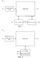
- the touch display system 10 includes a display panel 102, a display driving circuit 104, a monitoring circuit 106 and a touch controller 108.
- the touch display system 10 may be a touch display with touch-control function, such as a smart phone, tablet computer, etc.
- the display panel 102 may include a liquid crystal display panel, and the display driving circuit 104 is configured to drive the display panel 102; for example, the display driving circuit 104 may include a timing controller, a source driver, and a gate driver, wherein each pixel of the liquid crystal display panel is driven by the source driver and the gate driver according to the synchronizing signal and the control signal of the timing controller.
- the display panel 102 may also include the touch sensor (not shown in the drawing) therewithin, or the display panel 102 and the touch sensor may be disposed separately.
- the monitoring circuit 106 is configured to detect a sensing signal generated by the display driving circuit 104 when the display driving circuit 104 drives the display panel 102, and extract at least one synchronizing signal "sync" from the sensing signal; for example, a horizontal synchronizing signal "H_sync" for synchronizing each scan line of the panel or a gate driver vertical synchronizing signal "V_sync" for synchronizing each image.
- the touch controller 108 may drive and sense the touch sensor according to the synchronizing signal sync, thereby achieving the touch display synchronization with the display panel 102; that is, the display of the display panel is synchronized with the touch detection of the touch sensor.
- the monitoring circuit 106 achieves the synchronization between the touch controller 108 and the display panel 102 by sensing the sensing signal generated when the display driving circuit 104 drives the display panel 102 and extracting the synchronizing signal sync of the sensing signal, and then transmitting the synchronizing signal sync to the touch controller 108.
- the sensing signal may be a stray current generated by the coupling between the touch controller 108 or the touch sensor and the display panel 102; then, the monitoring circuit 106 extracts the synchronizing signal sync according to the frequency and phase of the sensing signal.
- the gate driver of the display driving circuit 104 drives a scan line of the display panel 102 under the control of the synchronizing signal
- a coupling capacitor is formed between the scan line and a sensing electrode of a touch sensor (not shown in the drawing) of the panel, thereby forming the stray current between the touch sensor when a pixel of the display panel 102 is conducted; next, after the monitoring circuit 106 detects the stray current, the monitoring circuit 106 extracts the synchronizing signal sync according to the frequency and the phase of the stray current.
- the monitoring circuit 106 may directly obtain the synchronizing signal sync via detection, thereby synchronizing the display driving circuit 104 and the touch controller 108.
- the monitoring circuit 106 may obtain the synchronizing signal according to the period of the driving signal that is sensed when the display driving circuit 104 drives the display panel 102. For example, after the touch controller 108 detects the sensing signal, the monitoring circuit 106 may sense the sensing signal generated when the display driving circuit 104 drives the display panel 102 and the period thereof via a horizontal blanking period of the source drive or a vertical blanking period of the gate drive, thereby generating the synchronizing signal; however, the present disclosure is not limited thereto.
- the touch display system 10 may be implemented in various forms.
- FIG 2 is a schematic view of another touch display system 20 according to some embodiments of the present disclosure.
- the touch display system 20 may be a touch display with touch-control function, such as a smart phone, tablet computer, etc.
- the touch display system 20 is similar to the touch display system 10 illustrated in Figure 1 , and hence, components and signals with similar functions are indicat4ed with the same reference numeral or symbol.
- the touch display system 20 differs from the touch display system 10 of Figure 1 in that the monitoring circuit 206 is included in the touch controller 208.
- the circuit 206 is used to detect a sensing signal of the display panel 102, and further extract or sense at least one synchronizing signal sync, and then provide the same to the touch controller 208 for further use.
- the monitoring circuit 206 of the touch controller 208 may extract to the sensing signal to generate the synchronizing signal sync, thereby synchronizing the display of the touch controller 208 and the display panel 102.
- the present touch display system 20 can achieve the synchronization of the touch controller 208 and the display driving circuit 104 without the installation of extra pins for connecting the display driving circuit 104 and the touch controller 208.
- both monitoring circuits can use the original sensing channel of the touch controller for performing the extraction or sensing of the sensing signal.
- the monitoring circuit and the touch controller may multiplex one of the sensing electrodes of the touch sensor to detect the sensing signal caused by the driving of the display panel; the term “multiplex" here means that a connection with the sensing electrode is formed at least during a synchronizing signal detection time or touch sensing period.
- FIG. 3 is a schematic view of a synchronization method 30 according to one embodiment of the present disclosure; detailed steps of the synchronization method 30 are as follows.
- Step 300 Start.
- Step 302 The Display driving circuit drives the display panel; a sensing signal is generated between the display panel and the touch sensor.
- Step 304 The monitoring circuit detects the sensing signal, and extracts the synchronizing signal sync from the sensing signal.
- Step 306 The touch controller and the display driving circuit are synchronized according to the synchronizing signal sync.
- Step 308 End.
- the touch display system 10, 20 can use the monitoring circuit 106, 206 to detect sensing signal generated between the display panel and the touch sensor when the display driving circuit 104 drives the display panel 102, and extract the synchronizing signal sync in the sensing signal, and provide the same to the touch controller 108, 208, thereby achieving the display synchronization with the display panel 102 and avoiding the interference to the touch controller 108, 208 caused by the display driving circuit 104.
- the touch display system 10 may be implemented in various forms.
- the touch display system 40 may be a touch display with touch-control function, such as a smart phone, tablet computer, etc.
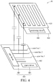
- the display system 40 may be an external touch display system, including a display panel 402, a display driving circuit 404, a monitoring circuit 406, a touch controller 408 and a touch sensor 410.
- the display panel 402 may be various display panels such as a liquid crystal display panel, and the display driving circuit 404 is configured to drive the display panel 402.
- the display driving circuit 404 may include a timing controller (not shown in the drawing), a source driver SD and a gate driver GD, wherein the source driver SD and the gate driver GD drives each pixel of the display panel 402 via the scan line or data line according to the synchronizing signal and control signal of the timing controller (for the sake of brevity, only the connection between the scan line and display panel 402 is depicted in Figure 4 ).
- the monitoring circuit 406 is included in the touch controller 408, and is configured to detect the sensing signal generated when the display driving circuit 404 drives the display panel 402, whereas the touch sensor 410 is configured to receive the pressing or touch from a user and generate a corresponding signal change according to said pressing or touch, wherein said signal change is detected by the touch controller 408 so that it can be used to determine the information such as the coordinate of the touch location.
- the touch controller 408 may further include a touch detecting circuit (not shown in the drawing) configured to output the driving signal to the touch sensor 410 according to the synchronizing signal.
- FIG. 5 is a schematic view of a touch controller 408 of the touch display system 40 depicted in Figure 4 according to one embodiment of the present disclosure.
- the touch controller 408 may include a plurality of receiving terminals RX1 ⁇ RXn, a plurality of transmitting terminals TX1 ⁇ TXm, an analog front end (AFE) circuit, an analog-to-digital converter (ADC) circuit and a monitoring circuit 406.
- AFE analog front end
- ADC analog-to-digital converter
- the display panel 402 is continuously driven to display the image no matter whether it receives the touch or not; specifically, the display driving circuit 404 generates the driving signal and loads it to the scan line, data line or pixel on the display panel 402; for example, the display driving circuit 404 of Figure 4 outputs the driving signal to the scan line under the control of the synchronizing signal, whereas the data line transmits the image data to each display pixel, thereby displaying the image.
- a coupling capacitor is formed between the scan line of the display panel 402 and the sensing electrode of the touch sensor 410, thereby resulting in a stray current, and by detecting a corresponding sensing signal using the receiving terminals (or the receiving channels, the sensing channels) RX1 ⁇ RXn of the touch controller 408, and after using the AFE circuit and ADC circuit to convert the sensing signal, the monitoring circuit 406 may further generate synchronizing signals Vsync, Hsync by extraction or sensing according to the frequency and the phase of the stray current generated between the scan line, data line or pixel of the display panel 402 and the touch sensor 410.
- the monitoring circuit 406 may also use the frequency and the phase of the stray current generated between the display driving circuit 404 and the touch sensor 410 when the display driving circuit 404 drives the data line or pixel to extract synchronizing signals Vsync, Hsync; however, the present disclosure is not limited thereto.
- Figure 6 is a schematic view illustrating a signal timing of the touch display system 40 according to one embodiment of the present disclosure.
- Figure 6 includes the signal timings of the synchronizing signals Vsync and Hsync, scan lines 1 ⁇ 3, and the receiving terminals RX1 and transmitting terminal TX1 of the touch controller 408; for the sake of brevity, the signals of the transmitting terminals TX2 ⁇ TXm and receiving terminals RX2 ⁇ RXn are not shown in the drawing.
- the display driving circuit 404 when the touch display system 40 performs the synchronization method between the display panel 402 and the touch controller 408, the display driving circuit 404 outputs the driving signal to the scan line under the control of the synchronizing signal, and a coupling capacitor is formed between the scan line and the sensing electrode of the touch sensor 410, thereby generating a stray current.
- the receiving terminals RX1 ⁇ RXn of the touch controller 408 is used to detect a corresponding sensing signal, and after the sensing signal is converted by the AFE circuit and ADC circuit, the monitoring circuit 406 may extract synchronizing signals Vsync, Hsync from the corresponding sensing signal detected by one or more of the receiving terminals RX1 ⁇ RXn, so that the touch controller 408 and the display driving circuit 104 are synchronized according to synchronizing signals Vsync, Hsync.
- the monitoring circuit 406 may extract the synchronizing signal Vsync from a period T1 of the driving signal of the drive scan lines 1 ⁇ 3, or extract the synchronizing signal Hsync from one of the periods T2, T3, T4 of the driving signal of the drive scan lines 1-3; moreover, the monitoring circuit 406 may extract the synchronizing signal Hsync according to a plurality of periods (e.g., T2-T4). In this way, the signal of the transmitting terminal TX1 may achieve synchronization according to the synchronizing signal Vsync.
- a connection between the synchronizing signal Vsync and the signal of the transmitting terminal TX1 as shown in Figure 6 is used to indicate that the signal synchronizing signal Vsync and the signal of the transmitting terminal TX1 are in the same period but with delayed synchronization states.
- the synchronizing signal Vsync and the signal of the transmitting terminal TX1 are in the same period and with a zero-delay synchronization state.
- the touch display system 40 when the touch display system 40 is performing the touch detection function and the synchronization method, the touch display system 40 may obtain the synchronizing signals Vsync, Hsync at the same time when the driving electrode or the sensing electrode of the touch sensor 410 is driven; in other words, the touch display system 40 may perform the touch detection function and the synchronization function concurrently.
- the touch display system 40 may use the sensing electrode to obtain the synchronizing signals Vsync, Hsync when the sensing electrode of the touch sensor 410 is not driven (i.e., when the touch detection is not executed).
- the touch display system 40 may use the sensing electrode to obtain the synchronizing signals Vsync, Hsync when the sensing electrode of the touch sensor 410 is not driven (i.e., when the touch detection is not executed).
- the touch display system 40 may use the sensing electrode to obtain the synchronizing signals Vsync, Hsync when the sensing electrode of the touch sensor 410 is not driven (i.e., when the touch detection is not executed).
- the touch controller 408 detects the synchronizing signal
- the transmitting terminals TX1 ⁇ TXm may perform the touch detection function at the same time; further, the embodiment of Figure 6 only describes using the synchronizing signal Vsync to synchronize the touch controller 408 and the display driving circuit 104; however, the present disclosure is not limited thereto; rather, it is feasible to use the synchronizing signal Hsync to achieve the same purpose; these embodiments are all applicable to the present disclosure.
- the foregoing embodiments are provided to discuss the spirits of the present disclosure, and persons having ordinary skill in the art may make appropriate modifications thereto.
- the monitoring circuit extracts the synchronizing signal from the sensing signal or sense the synchronizing signal
- other circuits or methods with the same function can be used to implement the present disclosure; however, the present disclosure is not limited thereto; these embodiments are all applicable to the present disclosure.
- the present touch display system achieves the synchronization between the touch controller and the display driving circuit using a synchronizing signal and avoids the interference touch controller caused by the display driving circuit.
Landscapes
- Engineering & Computer Science (AREA)
- Theoretical Computer Science (AREA)
- General Engineering & Computer Science (AREA)
- Physics & Mathematics (AREA)
- General Physics & Mathematics (AREA)
- Human Computer Interaction (AREA)
- Chemical & Material Sciences (AREA)
- Crystallography & Structural Chemistry (AREA)
- Computer Hardware Design (AREA)
- Position Input By Displaying (AREA)
- Control Of Indicators Other Than Cathode Ray Tubes (AREA)
Applications Claiming Priority (1)
| Application Number | Priority Date | Filing Date | Title |
|---|---|---|---|
| PCT/CN2018/076876 WO2019157735A1 (zh) | 2018-02-14 | 2018-02-14 | 触摸控制器、触控显示系统及触控显示同步方法 |
Publications (2)
| Publication Number | Publication Date |
|---|---|
| EP3553636A1 true EP3553636A1 (de) | 2019-10-16 |
| EP3553636A4 EP3553636A4 (de) | 2019-12-04 |
Family
ID=67620155
Family Applications (1)
| Application Number | Title | Priority Date | Filing Date |
|---|---|---|---|
| EP18871810.0A Pending EP3553636A4 (de) | 2018-02-14 | 2018-02-14 | Berührungssteuergerät, berührungsanzeigesystem und berührungsanzeigesynchronisierungsverfahren |
Country Status (4)
| Country | Link |
|---|---|
| US (1) | US10852885B2 (de) |
| EP (1) | EP3553636A4 (de) |
| CN (1) | CN110383219B (de) |
| WO (1) | WO2019157735A1 (de) |
Families Citing this family (8)
| Publication number | Priority date | Publication date | Assignee | Title |
|---|---|---|---|---|
| KR102754883B1 (ko) * | 2019-04-09 | 2025-01-17 | 삼성전자주식회사 | 터치 센서를 포함하는 전자 장치 및 전자 장치에 포함되는 터치 센서의 구동 방법 |
| CN113168268B (zh) * | 2019-11-08 | 2023-05-26 | 深圳市汇顶科技股份有限公司 | 触控检测方法、触控检测电路、触控芯片以及电子设备 |
| CN111930271B (zh) * | 2020-09-27 | 2021-01-22 | 深圳市汇顶科技股份有限公司 | 触控芯片、触控检测信号的处理方法和电子设备 |
| US11749173B2 (en) | 2021-07-15 | 2023-09-05 | Samsung Electronics Co., Ltd. | Electronic device configured to quickly update screen upon receiving input from peripheral device |
| CN113655902B (zh) * | 2021-07-26 | 2024-04-26 | 北京钛方科技有限责任公司 | 一种触摸信号确定方法、装置和存储介质 |
| CN114038426B (zh) * | 2021-12-13 | 2023-04-07 | Oppo广东移动通信有限公司 | 一种显示屏的显示驱动方法、触控驱动方法、芯片和终端 |
| US12189901B2 (en) | 2022-07-22 | 2025-01-07 | Apple Inc. | Split display driver circuitry to mitigate touch sensing system interaction |
| US20240423545A1 (en) * | 2023-06-22 | 2024-12-26 | Stmicroelectronics International N.V. | Non-invasive vital signs monitoring on a mobile device using an under-display optical sensor |
Family Cites Families (19)
| Publication number | Priority date | Publication date | Assignee | Title |
|---|---|---|---|---|
| KR20110059776A (ko) * | 2006-06-09 | 2011-06-03 | 애플 인크. | 터치 스크린 액정 디스플레이 |
| CN101833939B (zh) * | 2009-03-09 | 2012-03-28 | 财团法人工业技术研究院 | 触控显示系统及其驱动方法 |
| CN102906805A (zh) * | 2010-05-21 | 2013-01-30 | 夏普株式会社 | 显示装置及其驱动方法、以及显示系统 |
| KR101394937B1 (ko) * | 2010-09-07 | 2014-05-15 | 엘지디스플레이 주식회사 | 터치 센서를 갖는 표시 장치 및 그 방법 |
| KR101761580B1 (ko) * | 2010-09-08 | 2017-07-27 | 엘지디스플레이 주식회사 | 터치 센서를 갖는 표시 장치 |
| KR101788767B1 (ko) * | 2011-02-10 | 2017-10-23 | 삼성디스플레이 주식회사 | 터치 스크린 패널 |
| US20140267152A1 (en) * | 2013-03-12 | 2014-09-18 | Mircrochip Technology Incorporated | Force Sensing X-Y Touch Sensor |
| CN103376961A (zh) * | 2012-04-27 | 2013-10-30 | 联咏科技股份有限公司 | 触控装置以及其触控检测方法 |
| TWI469125B (zh) * | 2012-08-31 | 2015-01-11 | Au Optronics Corp | 觸控顯示裝置及顯示驅動方法 |
| JP2014067212A (ja) * | 2012-09-26 | 2014-04-17 | Appside Co Ltd | 静電容量式タッチパネル |
| US9965108B2 (en) * | 2014-05-16 | 2018-05-08 | Apple Inc. | Simultaneous self- and mutual capacitance sensing |
| CN105320319A (zh) * | 2014-06-30 | 2016-02-10 | 晨星半导体股份有限公司 | 触控式电子系统的触控装置及控制方法 |
| US9524697B2 (en) * | 2014-09-02 | 2016-12-20 | Stmicroelectronics Asia Pacific Pte Ltd | Capacitive touch screen display system including circuitry to address display perturbations induced by panel sensing |
| CN104199577B (zh) * | 2014-09-25 | 2017-02-15 | 深圳市华星光电技术有限公司 | 显示面板向触控面板提供同步信号的方法及电路 |
| KR102290990B1 (ko) * | 2014-10-06 | 2021-08-18 | 삼성전자주식회사 | 터치 아날로그 프론트 엔드 및 이를 포함하는 터치 센서 컨트롤러 |
| KR20160087481A (ko) * | 2015-01-13 | 2016-07-22 | 삼성디스플레이 주식회사 | 터치 스크린 패널 및 그의 구동방법 |
| CN105404429B (zh) * | 2015-12-24 | 2019-03-26 | 昆山工研院新型平板显示技术中心有限公司 | 触控电路和触控显示器件 |
| TWI582669B (zh) * | 2016-05-31 | 2017-05-11 | 郭柏良 | 提昇內嵌式觸控顯示面板畫面品質的觸控顯示驅動器及其驅動方法 |
| US10088965B2 (en) * | 2016-12-16 | 2018-10-02 | Stmicroelectronics Asia Pacific Pte Ltd | Reduction of noise in touch data samples via sampling during porch time of Vsync and Hsync signals |
-
2018
- 2018-02-14 CN CN201880000175.9A patent/CN110383219B/zh active Active
- 2018-02-14 EP EP18871810.0A patent/EP3553636A4/de active Pending
- 2018-02-14 WO PCT/CN2018/076876 patent/WO2019157735A1/zh not_active Ceased
-
2019
- 2019-05-10 US US16/409,048 patent/US10852885B2/en active Active
Also Published As
| Publication number | Publication date |
|---|---|
| CN110383219A (zh) | 2019-10-25 |
| US20190265859A1 (en) | 2019-08-29 |
| CN110383219B (zh) | 2023-06-16 |
| WO2019157735A1 (zh) | 2019-08-22 |
| US10852885B2 (en) | 2020-12-01 |
| EP3553636A4 (de) | 2019-12-04 |
Similar Documents
| Publication | Publication Date | Title |
|---|---|---|
| US10852885B2 (en) | Touch controller, touch display system and method for synchronizing touch display | |
| US20220291797A1 (en) | Active stylus downlink signal transmission timing control relative to sensor controller | |
| TWI475441B (zh) | 內嵌式觸控顯示面板及其驅動方法 | |
| US10318059B2 (en) | Touch sensing system and method of controlling the same | |
| KR102340937B1 (ko) | 스타일러스 펜, 및 터치 센싱 시스템과 그 구동방법 | |
| US10481718B2 (en) | Touch control method for touch panel, touch panel, active stylus for touch panel, and touch display apparatus including touch panel | |
| US12111996B2 (en) | Driving apparatus and operation method thereof | |
| US9268432B2 (en) | Touch panel having a master and slave controller and method for driving thereof | |
| US20100328237A1 (en) | Touch control system for controlling touch panel | |
| CN102006426B (zh) | 一种拼接系统的同步方法及其装置 | |
| US20150185914A1 (en) | Touch sensing system | |
| KR20170049668A (ko) | 터치 스크린을 갖는 표시장치와 그 구동 회로 | |
| US10133415B2 (en) | Touch display apparatus, driving circuit thereof and driving method therefor, and electronic apparatus | |
| TWI432753B (zh) | 測試系統及其測試方法 | |
| KR20230040460A (ko) | 터치구동장치 및 이를 포함하는 디스플레이장치 | |
| CN110047448B (zh) | 触摸面板控制装置、触摸面板控制方法及输入显示装置 | |
| US20090140781A1 (en) | Circuit for data synchronization of i2c time controller in display device and method thereof | |
| KR101429916B1 (ko) | 평판 표시장치와 그의 구동방법 | |
| KR20130078068A (ko) | 센싱구간 설정방법 및 상기 설정방법을 사용하는 터치스크린패널 구동시스템 | |
| KR20180002394A (ko) | 터치표시장치 및 이의 구동방법 | |
| CN101853147B (zh) | 笔记本电脑中检测外接式显示装置的电路与检测方法 | |
| KR102016572B1 (ko) | 터치 센싱 시스템 | |
| KR100357149B1 (ko) | 모니터의 화면조정 장치 및 방법 | |
| CN120295502A (zh) | 传感器控制器、方法及位置检测装置 | |
| CN116072033A (zh) | 显示驱动器以及显示装置 |
Legal Events
| Date | Code | Title | Description |
|---|---|---|---|
| STAA | Information on the status of an ep patent application or granted ep patent |
Free format text: STATUS: UNKNOWN |
|
| STAA | Information on the status of an ep patent application or granted ep patent |
Free format text: STATUS: THE INTERNATIONAL PUBLICATION HAS BEEN MADE |
|
| PUAI | Public reference made under article 153(3) epc to a published international application that has entered the european phase |
Free format text: ORIGINAL CODE: 0009012 |
|
| STAA | Information on the status of an ep patent application or granted ep patent |
Free format text: STATUS: REQUEST FOR EXAMINATION WAS MADE |
|
| 17P | Request for examination filed |
Effective date: 20190507 |
|
| AK | Designated contracting states |
Kind code of ref document: A1 Designated state(s): AL AT BE BG CH CY CZ DE DK EE ES FI FR GB GR HR HU IE IS IT LI LT LU LV MC MK MT NL NO PL PT RO RS SE SI SK SM TR |
|
| AX | Request for extension of the european patent |
Extension state: BA ME |
|
| A4 | Supplementary search report drawn up and despatched |
Effective date: 20191106 |
|
| RIC1 | Information provided on ipc code assigned before grant |
Ipc: G06F 3/041 20060101AFI20191030BHEP |
|
| RIN1 | Information on inventor provided before grant (corrected) |
Inventor name: LIN, YUNG-FU Inventor name: HSU, CHENG-CHUNG |
|
| DAV | Request for validation of the european patent (deleted) | ||
| DAX | Request for extension of the european patent (deleted) | ||
| STAA | Information on the status of an ep patent application or granted ep patent |
Free format text: STATUS: EXAMINATION IS IN PROGRESS |
|
| 17Q | First examination report despatched |
Effective date: 20211201 |