EP3553560A1 - Passiver radar mit analoger annullierung der statischen komponente - Google Patents
Passiver radar mit analoger annullierung der statischen komponente Download PDFInfo
- Publication number
- EP3553560A1 EP3553560A1 EP19167767.3A EP19167767A EP3553560A1 EP 3553560 A1 EP3553560 A1 EP 3553560A1 EP 19167767 A EP19167767 A EP 19167767A EP 3553560 A1 EP3553560 A1 EP 3553560A1
- Authority
- EP
- European Patent Office
- Prior art keywords
- signal
- passive radar
- transmitted
- estimate
- received
- Prior art date
- Legal status (The legal status is an assumption and is not a legal conclusion. Google has not performed a legal analysis and makes no representation as to the accuracy of the status listed.)
- Granted
Links
Images


Classifications
-
- G—PHYSICS
- G01—MEASURING; TESTING
- G01S—RADIO DIRECTION-FINDING; RADIO NAVIGATION; DETERMINING DISTANCE OR VELOCITY BY USE OF RADIO WAVES; LOCATING OR PRESENCE-DETECTING BY USE OF THE REFLECTION OR RERADIATION OF RADIO WAVES; ANALOGOUS ARRANGEMENTS USING OTHER WAVES
- G01S13/00—Systems using the reflection or reradiation of radio waves, e.g. radar systems; Analogous systems using reflection or reradiation of waves whose nature or wavelength is irrelevant or unspecified
- G01S13/87—Combinations of radar systems, e.g. primary radar and secondary radar
- G01S13/878—Combination of several spaced transmitters or receivers of known location for determining the position of a transponder or a reflector
-
- G—PHYSICS
- G01—MEASURING; TESTING
- G01S—RADIO DIRECTION-FINDING; RADIO NAVIGATION; DETERMINING DISTANCE OR VELOCITY BY USE OF RADIO WAVES; LOCATING OR PRESENCE-DETECTING BY USE OF THE REFLECTION OR RERADIATION OF RADIO WAVES; ANALOGOUS ARRANGEMENTS USING OTHER WAVES
- G01S13/00—Systems using the reflection or reradiation of radio waves, e.g. radar systems; Analogous systems using reflection or reradiation of waves whose nature or wavelength is irrelevant or unspecified
- G01S13/003—Bistatic radar systems; Multistatic radar systems
-
- G—PHYSICS
- G01—MEASURING; TESTING
- G01S—RADIO DIRECTION-FINDING; RADIO NAVIGATION; DETERMINING DISTANCE OR VELOCITY BY USE OF RADIO WAVES; LOCATING OR PRESENCE-DETECTING BY USE OF THE REFLECTION OR RERADIATION OF RADIO WAVES; ANALOGOUS ARRANGEMENTS USING OTHER WAVES
- G01S13/00—Systems using the reflection or reradiation of radio waves, e.g. radar systems; Analogous systems using reflection or reradiation of waves whose nature or wavelength is irrelevant or unspecified
- G01S13/02—Systems using reflection of radio waves, e.g. primary radar systems; Analogous systems
- G01S13/06—Systems determining position data of a target
- G01S13/46—Indirect determination of position data
-
- G—PHYSICS
- G01—MEASURING; TESTING
- G01S—RADIO DIRECTION-FINDING; RADIO NAVIGATION; DETERMINING DISTANCE OR VELOCITY BY USE OF RADIO WAVES; LOCATING OR PRESENCE-DETECTING BY USE OF THE REFLECTION OR RERADIATION OF RADIO WAVES; ANALOGOUS ARRANGEMENTS USING OTHER WAVES
- G01S13/00—Systems using the reflection or reradiation of radio waves, e.g. radar systems; Analogous systems using reflection or reradiation of waves whose nature or wavelength is irrelevant or unspecified
- G01S13/02—Systems using reflection of radio waves, e.g. primary radar systems; Analogous systems
- G01S13/50—Systems of measurement based on relative movement of target
- G01S13/52—Discriminating between fixed and moving objects or between objects moving at different speeds
- G01S13/522—Discriminating between fixed and moving objects or between objects moving at different speeds using transmissions of interrupted pulse modulated waves
-
- G—PHYSICS
- G01—MEASURING; TESTING
- G01S—RADIO DIRECTION-FINDING; RADIO NAVIGATION; DETERMINING DISTANCE OR VELOCITY BY USE OF RADIO WAVES; LOCATING OR PRESENCE-DETECTING BY USE OF THE REFLECTION OR RERADIATION OF RADIO WAVES; ANALOGOUS ARRANGEMENTS USING OTHER WAVES
- G01S7/00—Details of systems according to groups G01S13/00, G01S15/00, G01S17/00
- G01S7/02—Details of systems according to groups G01S13/00, G01S15/00, G01S17/00 of systems according to group G01S13/00
- G01S7/35—Details of non-pulse systems
- G01S7/352—Receivers
- G01S7/354—Extracting wanted echo-signals
-
- G—PHYSICS
- G01—MEASURING; TESTING
- G01S—RADIO DIRECTION-FINDING; RADIO NAVIGATION; DETERMINING DISTANCE OR VELOCITY BY USE OF RADIO WAVES; LOCATING OR PRESENCE-DETECTING BY USE OF THE REFLECTION OR RERADIATION OF RADIO WAVES; ANALOGOUS ARRANGEMENTS USING OTHER WAVES
- G01S7/00—Details of systems according to groups G01S13/00, G01S15/00, G01S17/00
- G01S7/02—Details of systems according to groups G01S13/00, G01S15/00, G01S17/00 of systems according to group G01S13/00
- G01S7/40—Means for monitoring or calibrating
- G01S7/4004—Means for monitoring or calibrating of parts of a radar system
- G01S7/4021—Means for monitoring or calibrating of parts of a radar system of receivers
-
- G—PHYSICS
- G01—MEASURING; TESTING
- G01S—RADIO DIRECTION-FINDING; RADIO NAVIGATION; DETERMINING DISTANCE OR VELOCITY BY USE OF RADIO WAVES; LOCATING OR PRESENCE-DETECTING BY USE OF THE REFLECTION OR RERADIATION OF RADIO WAVES; ANALOGOUS ARRANGEMENTS USING OTHER WAVES
- G01S13/00—Systems using the reflection or reradiation of radio waves, e.g. radar systems; Analogous systems using reflection or reradiation of waves whose nature or wavelength is irrelevant or unspecified
- G01S13/02—Systems using reflection of radio waves, e.g. primary radar systems; Analogous systems
- G01S13/06—Systems determining position data of a target
- G01S13/46—Indirect determination of position data
- G01S2013/462—Indirect determination of position data using multipath signals
Definitions
- the field of the invention is that of so-called passive radars, which use signals emitted by non-cooperative transmitters in order to detect and locate targets.
- a passive radar is a surveillance system for detecting (and possibly locating and estimating speed and orientation) moving targets. But unlike an active conventional radar, a passive radar does not integrate a radiofrequency transmitter to illuminate its targets. This system is described as opportunistic insofar as it benefits from the presence of non-cooperative third-party transmitters already present in the area to be monitored. These transmitters are, for example, broadcasting, broadcasting or telecommunication transmitters in an external context, and for example Wi-Fi access points in an interior context.
- the passive radar receives the transmitted signal "routed" from multiple paths: the line of sight (or direct path), the paths passing through fixed reflectors (relief, vegetation, buildings, etc.) and finally the possible paths due the presence of reflectors of interest in displacement (the targets).
- the received signal is thus broken down into a static contribution related to the propagation of the signal transmitted through a multipath propagation channel (ie linked to the propagation of the signal transmitted in line of sight and to the propagation of echoes of the signal emitted from fixed reflectors) and a dynamic contribution related to echo propagation of the transmitted signal from moving targets
- the determination of the time difference between the line of sight line Tv and the reflected path Tr by the moving target C makes it possible to restrict the position of the target to an ellipse E whose foci are the TX transmitter and RX passive radar positions.
- a network antennas at the passive radar it is possible to form an agile radiation beam and scan the area of interest to find the angle of the reflected signal.
- the angle information is used to identify the point of the ellipse and thus the position of the target. This assumes knowing the position of the passive radar, the position of the uncooperative transmitter and the course of the agile beam in the analysis frame.
- the use of several non-cooperative transmitters TX1, TX2, TX3 makes it possible to dispense with an antenna that is agile in radiation.
- the desired position of the target C actually corresponds to the intersection of ellipses E1, E2, E3 whose focus are on the one hand the position of the passive radar RX and on the other hand the positions of the different non-cooperative transmitters TX1, TX2 , TX3.
- the object of the invention is to propose a technique capable of facilitating the step of searching for the target.
- a passive radar which comprises an antenna for receiving a signal emitted by a non-cooperative transmitter which comprises known sequences of the passive radar.
- the received signal comprises a static contribution related to the propagation of the signal transmitted through a multipath propagation channel and a dynamic contribution related to the propagation of the echoes of the signal transmitted from a moving target.
- the passive radar includes a reception chain that includes an analog-to-digital converter capable of providing a digitized signal, a mobile target detection unit from the digitized signal, and a digitized signal processing unit configured to determine, when a calibration phase of the passive radar, an estimation of the static contribution.
- the processing unit is more particularly configured, during the calibration phase of the passive radar, to synchronize the received signal with the signal transmitted from the known sequences and to determine an estimate of the multipath propagation channel from synchronized received signal and known sequences.
- the passive radar is furthermore equipped with a transmission system capable of delivering an analog signal representative of the estimation of the static contribution, and of a coupler configured to supply the reception chain with the signal received during the phase. of the passive radar, and the received signal to which is subtracted the analog signal representative of the estimate of the static contribution during a passive radar use phase for the mobile target detection.
- the passive radar of the invention is an opportunistic system taking advantage of the presence of non-cooperative third-party transmitters already present on the area to be monitored.
- This passive radar aims to detect and determine the location (or orientation) of moving objects by the signals emitted by one or more non-cooperative transmitters whose known location relative to the radar, such as transmitters of telecommunications networks. such as 4G networks.
- the transmitter 10 comprises a digital generator 50 of data frames in which there is a preamble Sc and useful data D, a data channel.
- transmission 60 which comprises a digital-to-analog converter 610 and a radio frequency transmitter 620 which transposes, filters and amplifies the analog signal at the desired frequency and a transmitting antenna 20.
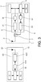
- the passive radar 1 comprises correspondingly a reception antenna 2 of the signal transmitted by the transmitter 10 and a reception channel 3 which comprises a radio frequency receiver 31 which amplifies, filters and transposes the received signal and an analog-digital converter 32 which provides a digitized signal.
- This digitized signal is supplied to a mobile target detection unit 4 which implements a conventional passive radar algorithm, for example by seeking the most probable Doppler delay-frequency torque.
- a mobile target detection unit 4 which implements a conventional passive radar algorithm, for example by seeking the most probable Doppler delay-frequency torque.
- An example of such an algorithm in the case where the receiving antenna 2 is an antenna array is presented in the article of CR Berger et al., "Signal processing for passive radar using OFDM waveforms," J. Sel. Topics Signal Process., Pp. 226-238, 2010 .
- the propagation channel between the transmitter 10 and the passive radar 1 may consist of a direct path and multi-path and, if appropriate, a reflection on a target of interest.
- the received signal comprises a static contribution related to the propagation of the signal transmitted through a multipath propagation channel (ie linked to the propagation of the signal sent in line of sight and to the propagation of echoes of the transmitted signal from fixed reflectors) and, where appropriate, a dynamic contribution related to echo propagation of the transmitted signal from one or more moving targets.
- the passive radar thus achieves an analog cancellation of the static contribution by generating a signal which corresponds, at the output of the directional coupler, to the signals received in the absence of moving targets.
- the power difference between the static contribution and the dynamic contribution is reduced (of the order of 30 to 40 dB), which makes it possible to gain in coding dynamics (and thus in precision when quantifying the analog signals) and to reduce the complexity of the filtering implemented in the mobile target detection unit 4.
- the coupler 7 is preferably a directional coupler so as to prevent the analog signal representative of the estimate of the static contribution which is subtracted from the received signal from returning to the antenna 2.
- the directional coupler thus injects directionally the analog signal representative of the estimation of the static contribution to the reception chain, with for example losses of 10dB on this signal towards the reception channel and losses of 30dB on this signal towards the antenna.
- a circulator can be inserted between the antenna 2 and the coupler 7 in order to reduce the power of the analog signal representative of the estimate of the static contribution that can be received by the antenna.
- the circulator comprises a port 1 connected to the antenna, a port 2 connected to the coupler and a port 3 connected to a load adapted to neutralize the energy of the analog signal representative of the estimate of the static contribution that goes back to the antenna .
- the signal emitted by the non-cooperative transmitter 10 comprises known sequences of the passive radar (over a time duration and a frequency band), for example the preambles Sc. It is for example a wide signal multi-carrier band, for example an OFDM signal transmitted by a base station of a 4G LTE telecommunications network or by a Wi-Fi access point. It may also be a mono modulated narrow band signal -porteuse.
- the digitized signal processing unit 5 is then configured, during the calibration phase of the passive radar, to achieve a time-frequency synchronization of the received signal with the signal emitted from the known sequences and for determining an estimate of the multipath propagation channel from the synchronized received signal and known sequences. With the knowledge of the known sequences and the estimation of the multipath propagation channel, the unit 5 can generate a numerical estimation of the static contribution during the reception of the known sequences.
- This numerical estimation is supplied to the transmission system 6 which will then deliver the analog signal representative of the estimation of the static contribution during the reception of the known sequences.
- the coupler 7 subtracts this analog signal from the received signal, the result of the subtraction being digitized by the converter 32.
- the mobile target detection unit 4 operates in turn, during the use phase of the passive radar, the digitized signal during the reception of the known sequences (ie over the duration of the known sequences).
- the figure 4 illustrates the calibration phase of the passive radar of the invention.
- the radar 1 receives the signals Tx1, Tx2 emitted by two non-cooperative emitters E1, E2 in the form of frames consisting respectively of a preamble P1, P2 and of useful data D1, D2.
- the received signal is designated Rx.
- the multipath propagation channel between the emitter E1 and the passive radar 1 has a pulse response h1 and the multipath propagation channel between the emitter E2 and the passive radar 2 has an impulse response h2.
- the passive radar 1 estimates each of the multipath propagation channels to provide estimated impulse responses. h 1 ⁇ , h 2 ⁇ (in its time-frequency basis) and generate the numerical estimation of the static contribution Txa during the reception of the preambles with the knowledge of the preambles P1, P2 and the estimate of each of the multipath propagation channels.
- the transmitters E1 and E2 use different frequency bands (for example bands allocated to different cellular telecommunications network operators) and the passive radar can switch between these frequency bands to listen to one transmitter at a time.
- different frequency bands for example bands allocated to different cellular telecommunications network operators
- the passive radar In order to estimate each of the multi-path propagation channels, the passive radar first synchronises, in particular a time-frequency synchronization in its time and frequency base, the signal received with the signal transmitted by each transmitter. For this purpose, it exploits the preambles contained in the frames sent by each transmitter.
- This synchronization relates to a synchronization in time TO ("Timing Offset") carried out on the direct path (the strongest, and the first arrived), a frequency synchronization CFO ("Carrier Frequency Offset”) to compensate the Doppler shift between the analog signals at the radiofrequency transmitter 620 and the radiofrequency receiver 31 and a synchronization of the SFO rhythm (“Sampling Frequency Offset”) to compensate for the offset of the timing between the digital input signals of the digital-to-analog converter 610 and the output of the analog-digital converter 32.
- Timing Offset time TO
- CFO Carrier Frequency Offset
- SFO rhythm synchronization of the SFO rhythm
- An example of such a synchronization is given in the article of M. Morelli et al., "Synchronization techniques for orthogonal frequency division multiple access (OFDMA): A tutorial review", Proc. IEEE, vol. 95, no. 7, pp. 1394-1427, July 2007 .
- the passive radar estimates, for each transmitter, the corresponding propagation channel.
- Different estimation techniques can be implemented and we can find examples in the article of MK Ozdemir et al., "Channel estimation for wireless OFDM systems," IEEE Communications Surveys & tutorials, vol. 9, no. 2, pp. 18-48, Second Quarter 2007 .
- the estimated impulse responses h 1 ⁇ , h 2 ⁇ may be adjusted according to the observed error between the sequences actually received h1P1, h2P2 and their estimates h 1 ⁇ P 1 , h 2 ⁇ P 2.
- the figure 5 illustrates the phase of use of the passive radar of the invention for the detection of targets C.
- the transmission chain 6 of the passive radar generates the analog signal representative of the estimate of the static contribution during the reception of the known sequences and the coupler 7 subtracts this analog signal from the signal received via the reception antenna 2.
- the passive radar according to the invention preferably comprises a single reception antenna 2, and therefore a single reception channel.
- This single receiving antenna can be a scanning directive antenna by means of which it is possible to scan the area of interest and identify the position of the target on the ellipse.
- the single antenna can be used to receive signals transmitted by a plurality of non-cooperative transmitters. The position of the target can then be determined at the intersection of the ellipses associated with each of the transmitters.
- the passive radar according to the invention may also comprise a plurality of reception antennas each associated with a reception channel 3, a digitized signal processing unit 5, a transmission channel 6 and a coupler 7.
- a reception channel 3 a reception channel 3
- a digitized signal processing unit 5 a transmission channel 6
- a coupler 7 a coupler 7.
- the generation and the subtraction of an analog signal of cancellation of the static component is carried out for each of the antennas.
- digital clocks (based on a single reference) and local oscillators are distributed to all reception and transmission channels.
Landscapes
- Engineering & Computer Science (AREA)
- Radar, Positioning & Navigation (AREA)
- Remote Sensing (AREA)
- Computer Networks & Wireless Communication (AREA)
- Physics & Mathematics (AREA)
- General Physics & Mathematics (AREA)
- Radar Systems Or Details Thereof (AREA)
Applications Claiming Priority (1)
| Application Number | Priority Date | Filing Date | Title |
|---|---|---|---|
| FR1853175A FR3080187B1 (fr) | 2018-04-11 | 2018-04-11 | Radar passif a annulation analogique de la composante statique |
Publications (2)
| Publication Number | Publication Date |
|---|---|
| EP3553560A1 true EP3553560A1 (de) | 2019-10-16 |
| EP3553560B1 EP3553560B1 (de) | 2020-11-11 |
Family
ID=63294322
Family Applications (1)
| Application Number | Title | Priority Date | Filing Date |
|---|---|---|---|
| EP19167767.3A Active EP3553560B1 (de) | 2018-04-11 | 2019-04-08 | Passiver radar mit analoger annullierung der statischen komponente |
Country Status (3)
| Country | Link |
|---|---|
| US (1) | US11086003B2 (de) |
| EP (1) | EP3553560B1 (de) |
| FR (1) | FR3080187B1 (de) |
Families Citing this family (6)
| Publication number | Priority date | Publication date | Assignee | Title |
|---|---|---|---|---|
| US10938615B2 (en) * | 2018-04-02 | 2021-03-02 | Maxlinear, Inc. | Signaling in an orthogonal frequency division multiplexed radar system |
| US11703582B2 (en) | 2019-12-06 | 2023-07-18 | Qualcomm Incorporated | Multistatic radar measurement |
| US11892559B2 (en) * | 2019-12-18 | 2024-02-06 | Rohde & Schwarz Gmbh & Co. Kg | Radar calibration system and method for moving a radar calibration target along a desired movement path |
| US11754663B2 (en) * | 2020-06-11 | 2023-09-12 | Qualcomm Incorporated | Additional feedback for location detection of device-free objects using wireless communication signals |
| CN112305526B (zh) * | 2020-10-22 | 2023-05-26 | 电子科技大学 | 一种基于外置标校源的分布式阵列系统同步方法 |
| FI130773B1 (fi) * | 2021-01-05 | 2024-03-11 | Teknologian Tutkimuskeskus Vtt Oy | Verkkosolmu jätteenhallintajärjestelmään |
Citations (1)
| Publication number | Priority date | Publication date | Assignee | Title |
|---|---|---|---|---|
| US20150355322A1 (en) * | 2013-02-25 | 2015-12-10 | Mitsubishi Electric Corporation | Passive radar device |
Family Cites Families (4)
| Publication number | Priority date | Publication date | Assignee | Title |
|---|---|---|---|---|
| GB2514103B (en) * | 2013-05-12 | 2017-08-02 | Microsense Solutions Ltd | Bidirectional bistatic radar perimeter intrusion detection system |
| FR3046513A1 (fr) | 2016-01-04 | 2017-07-07 | Commissariat Energie Atomique | Emetteur recepteur ibfd a module de transposition de frequence non reciproque |
| US10473759B2 (en) * | 2017-03-28 | 2019-11-12 | GM Global Technology Operations LLC | Tool for automatic multiple radar calibration |
| KR102687795B1 (ko) * | 2017-05-12 | 2024-07-23 | 로카타 코퍼레이션 피티와이 리미티드 | 사용자 플랫폼의 환경을 특징짓는 방법 및 장치 |
-
2018
- 2018-04-11 FR FR1853175A patent/FR3080187B1/fr active Active
-
2019
- 2019-04-08 EP EP19167767.3A patent/EP3553560B1/de active Active
- 2019-04-08 US US16/377,593 patent/US11086003B2/en active Active
Patent Citations (1)
| Publication number | Priority date | Publication date | Assignee | Title |
|---|---|---|---|---|
| US20150355322A1 (en) * | 2013-02-25 | 2015-12-10 | Mitsubishi Electric Corporation | Passive radar device |
Non-Patent Citations (2)
| Title |
|---|
| BERTHILLOT CLEMENT ET AL: "BEM Reference Signal Estimation for an Airborne Passive Radar Antenna Array", IEEE TRANSACTIONS ON AEROSPACE AND ELECTRONIC SYSTEMS, IEEE SERVICE CENTER, PISCATAWAY, NJ, US, vol. 53, no. 6, 1 December 2017 (2017-12-01), pages 2833 - 2845, XP011673987, ISSN: 0018-9251, [retrieved on 20171205], DOI: 10.1109/TAES.2017.2716458 * |
| BOLVARDI HASAN ET AL: "Dynamic Clutter Suppression and Multitarget Detection in a DVB-T-Based Passive Radar", IEEE TRANSACTIONS ON AEROSPACE AND ELECTRONIC SYSTEMS, IEEE SERVICE CENTER, PISCATAWAY, NJ, US, vol. 53, no. 4, 1 August 2017 (2017-08-01), pages 1812 - 1825, XP011658442, ISSN: 0018-9251, [retrieved on 20170807], DOI: 10.1109/TAES.2017.2674138 * |
Also Published As
| Publication number | Publication date |
|---|---|
| FR3080187A1 (fr) | 2019-10-18 |
| US20190317203A1 (en) | 2019-10-17 |
| EP3553560B1 (de) | 2020-11-11 |
| US11086003B2 (en) | 2021-08-10 |
| FR3080187B1 (fr) | 2020-05-08 |
Similar Documents
| Publication | Publication Date | Title |
|---|---|---|
| EP3553560B1 (de) | Passiver radar mit analoger annullierung der statischen komponente | |
| EP1500951B1 (de) | Verfahren zur multistatischen Detektion und Ortung eines beweglichen Objektes mittels digitaler Rundfunksender | |
| EP3906426B1 (de) | Kohärentes wi-fi-radar mit einem drahtlosen zugangspunkt | |
| US7151483B2 (en) | System and method for concurrent operation of multiple radar or active sonar systems on a common frequency | |
| US10838035B2 (en) | Characterizing multipath delays in antenna array and synthetic aperture radar systems | |
| EP0681190B1 (de) | System und Verfahren zur diskreten Radarerkennung | |
| CN113759359B (zh) | 基于空管雷达的无源双基地雷达接收装置及目标探测方法 | |
| JP2017525949A (ja) | 位相符号化データチャネルを有するfmcwレーダ | |
| FR2964289A1 (fr) | Procede et dispositif de localisation d'au moins un obstacle dans un reseau de communication, programme d'ordinateur correspondant. | |
| CN117440397A (zh) | 感知处理方法、装置、终端、网络侧设备及可读存储介质 | |
| NO340278B1 (no) | Fremgangsmåte for å detektere bistatisk modus ved passivt å operere på ikke-samvirkende radioelektriske sendinger | |
| AU2018265772A1 (en) | Methods and apparatus for characterising the environment of a user platform | |
| US20210165073A1 (en) | Digital radar imaging using 5g-nr millimeter wave base station antenna solutions | |
| EP0903049B1 (de) | Verfahren zur einleitung des weiterreichens von gesprächen in einem zellularfunksystem | |
| WO2024032538A1 (zh) | 校准方法、信息传输方法、装置及通信设备 | |
| FR2737307A1 (fr) | Systeme de mesure de distance | |
| CN117440398A (zh) | 感知处理方法、装置、终端、网络侧设备及可读存储介质 | |
| Marin et al. | Monostatic FMCW radar architecture for multifunction full-duplex radios | |
| CN112051550B (zh) | 一种用于gps信号的外辐射源直达波抑制方法 | |
| WO2024149184A1 (zh) | 传输处理方法、装置、终端及网络侧设备 | |
| Radmard et al. | Receivers’ positioning in multiple-input multiple-output digital video broadcast-terrestrial-based passive coherent location | |
| WO2024131689A1 (zh) | 感知方法、感知装置及通信设备 | |
| Sark et al. | An approach for implementation of ranging and positioning methods on a software defined radio | |
| EP3400457B1 (de) | Verfahren zum löschen eines signals aus einem bordradar | |
| Zhang et al. | A Novel Map Matching Based Localization Method for ISAC |
Legal Events
| Date | Code | Title | Description |
|---|---|---|---|
| PUAI | Public reference made under article 153(3) epc to a published international application that has entered the european phase |
Free format text: ORIGINAL CODE: 0009012 |
|
| STAA | Information on the status of an ep patent application or granted ep patent |
Free format text: STATUS: REQUEST FOR EXAMINATION WAS MADE |
|
| 17P | Request for examination filed |
Effective date: 20190408 |
|
| AK | Designated contracting states |
Kind code of ref document: A1 Designated state(s): AL AT BE BG CH CY CZ DE DK EE ES FI FR GB GR HR HU IE IS IT LI LT LU LV MC MK MT NL NO PL PT RO RS SE SI SK SM TR |
|
| AX | Request for extension of the european patent |
Extension state: BA ME |
|
| GRAJ | Information related to disapproval of communication of intention to grant by the applicant or resumption of examination proceedings by the epo deleted |
Free format text: ORIGINAL CODE: EPIDOSDIGR1 |
|
| STAA | Information on the status of an ep patent application or granted ep patent |
Free format text: STATUS: GRANT OF PATENT IS INTENDED |
|
| GRAP | Despatch of communication of intention to grant a patent |
Free format text: ORIGINAL CODE: EPIDOSNIGR1 |
|
| RIC1 | Information provided on ipc code assigned before grant |
Ipc: G01S 13/87 20060101AFI20200508BHEP Ipc: G01S 7/35 20060101ALI20200508BHEP Ipc: G01S 13/00 20060101ALI20200508BHEP |
|
| INTG | Intention to grant announced |
Effective date: 20200602 |
|
| RAP1 | Party data changed (applicant data changed or rights of an application transferred) |
Owner name: COMMISSARIAT A L'ENERGIE ATOMIQUE ET AUX ENERGIES ALTERNATIVES |
|
| RIN1 | Information on inventor provided before grant (corrected) |
Inventor name: ROSSON, PATRICK |
|
| GRAS | Grant fee paid |
Free format text: ORIGINAL CODE: EPIDOSNIGR3 |
|
| GRAA | (expected) grant |
Free format text: ORIGINAL CODE: 0009210 |
|
| STAA | Information on the status of an ep patent application or granted ep patent |
Free format text: STATUS: THE PATENT HAS BEEN GRANTED |
|
| AK | Designated contracting states |
Kind code of ref document: B1 Designated state(s): AL AT BE BG CH CY CZ DE DK EE ES FI FR GB GR HR HU IE IS IT LI LT LU LV MC MK MT NL NO PL PT RO RS SE SI SK SM TR |
|
| REG | Reference to a national code |
Ref country code: GB Ref legal event code: FG4D Free format text: NOT ENGLISH |
|
| REG | Reference to a national code |
Ref country code: CH Ref legal event code: EP |
|
| REG | Reference to a national code |
Ref country code: AT Ref legal event code: REF Ref document number: 1334018 Country of ref document: AT Kind code of ref document: T Effective date: 20201115 |
|
| REG | Reference to a national code |
Ref country code: DE Ref legal event code: R096 Ref document number: 602019001253 Country of ref document: DE |
|
| REG | Reference to a national code |
Ref country code: IE Ref legal event code: FG4D Free format text: LANGUAGE OF EP DOCUMENT: FRENCH |
|
| REG | Reference to a national code |
Ref country code: NL Ref legal event code: MP Effective date: 20201111 |
|
| REG | Reference to a national code |
Ref country code: AT Ref legal event code: MK05 Ref document number: 1334018 Country of ref document: AT Kind code of ref document: T Effective date: 20201111 |
|
| PG25 | Lapsed in a contracting state [announced via postgrant information from national office to epo] |
Ref country code: NO Free format text: LAPSE BECAUSE OF FAILURE TO SUBMIT A TRANSLATION OF THE DESCRIPTION OR TO PAY THE FEE WITHIN THE PRESCRIBED TIME-LIMIT Effective date: 20210211 Ref country code: GR Free format text: LAPSE BECAUSE OF FAILURE TO SUBMIT A TRANSLATION OF THE DESCRIPTION OR TO PAY THE FEE WITHIN THE PRESCRIBED TIME-LIMIT Effective date: 20210212 Ref country code: RS Free format text: LAPSE BECAUSE OF FAILURE TO SUBMIT A TRANSLATION OF THE DESCRIPTION OR TO PAY THE FEE WITHIN THE PRESCRIBED TIME-LIMIT Effective date: 20201111 Ref country code: PT Free format text: LAPSE BECAUSE OF FAILURE TO SUBMIT A TRANSLATION OF THE DESCRIPTION OR TO PAY THE FEE WITHIN THE PRESCRIBED TIME-LIMIT Effective date: 20210311 Ref country code: FI Free format text: LAPSE BECAUSE OF FAILURE TO SUBMIT A TRANSLATION OF THE DESCRIPTION OR TO PAY THE FEE WITHIN THE PRESCRIBED TIME-LIMIT Effective date: 20201111 |
|
| PG25 | Lapsed in a contracting state [announced via postgrant information from national office to epo] |
Ref country code: IS Free format text: LAPSE BECAUSE OF FAILURE TO SUBMIT A TRANSLATION OF THE DESCRIPTION OR TO PAY THE FEE WITHIN THE PRESCRIBED TIME-LIMIT Effective date: 20210311 Ref country code: PL Free format text: LAPSE BECAUSE OF FAILURE TO SUBMIT A TRANSLATION OF THE DESCRIPTION OR TO PAY THE FEE WITHIN THE PRESCRIBED TIME-LIMIT Effective date: 20201111 Ref country code: LV Free format text: LAPSE BECAUSE OF FAILURE TO SUBMIT A TRANSLATION OF THE DESCRIPTION OR TO PAY THE FEE WITHIN THE PRESCRIBED TIME-LIMIT Effective date: 20201111 Ref country code: SE Free format text: LAPSE BECAUSE OF FAILURE TO SUBMIT A TRANSLATION OF THE DESCRIPTION OR TO PAY THE FEE WITHIN THE PRESCRIBED TIME-LIMIT Effective date: 20201111 Ref country code: BG Free format text: LAPSE BECAUSE OF FAILURE TO SUBMIT A TRANSLATION OF THE DESCRIPTION OR TO PAY THE FEE WITHIN THE PRESCRIBED TIME-LIMIT Effective date: 20210211 Ref country code: AT Free format text: LAPSE BECAUSE OF FAILURE TO SUBMIT A TRANSLATION OF THE DESCRIPTION OR TO PAY THE FEE WITHIN THE PRESCRIBED TIME-LIMIT Effective date: 20201111 |
|
| REG | Reference to a national code |
Ref country code: LT Ref legal event code: MG9D |
|
| PG25 | Lapsed in a contracting state [announced via postgrant information from national office to epo] |
Ref country code: HR Free format text: LAPSE BECAUSE OF FAILURE TO SUBMIT A TRANSLATION OF THE DESCRIPTION OR TO PAY THE FEE WITHIN THE PRESCRIBED TIME-LIMIT Effective date: 20201111 |
|
| PG25 | Lapsed in a contracting state [announced via postgrant information from national office to epo] |
Ref country code: CZ Free format text: LAPSE BECAUSE OF FAILURE TO SUBMIT A TRANSLATION OF THE DESCRIPTION OR TO PAY THE FEE WITHIN THE PRESCRIBED TIME-LIMIT Effective date: 20201111 Ref country code: EE Free format text: LAPSE BECAUSE OF FAILURE TO SUBMIT A TRANSLATION OF THE DESCRIPTION OR TO PAY THE FEE WITHIN THE PRESCRIBED TIME-LIMIT Effective date: 20201111 Ref country code: SK Free format text: LAPSE BECAUSE OF FAILURE TO SUBMIT A TRANSLATION OF THE DESCRIPTION OR TO PAY THE FEE WITHIN THE PRESCRIBED TIME-LIMIT Effective date: 20201111 Ref country code: SM Free format text: LAPSE BECAUSE OF FAILURE TO SUBMIT A TRANSLATION OF THE DESCRIPTION OR TO PAY THE FEE WITHIN THE PRESCRIBED TIME-LIMIT Effective date: 20201111 Ref country code: LT Free format text: LAPSE BECAUSE OF FAILURE TO SUBMIT A TRANSLATION OF THE DESCRIPTION OR TO PAY THE FEE WITHIN THE PRESCRIBED TIME-LIMIT Effective date: 20201111 Ref country code: RO Free format text: LAPSE BECAUSE OF FAILURE TO SUBMIT A TRANSLATION OF THE DESCRIPTION OR TO PAY THE FEE WITHIN THE PRESCRIBED TIME-LIMIT Effective date: 20201111 |
|
| REG | Reference to a national code |
Ref country code: DE Ref legal event code: R097 Ref document number: 602019001253 Country of ref document: DE |
|
| PG25 | Lapsed in a contracting state [announced via postgrant information from national office to epo] |
Ref country code: DK Free format text: LAPSE BECAUSE OF FAILURE TO SUBMIT A TRANSLATION OF THE DESCRIPTION OR TO PAY THE FEE WITHIN THE PRESCRIBED TIME-LIMIT Effective date: 20201111 |
|
| PLBE | No opposition filed within time limit |
Free format text: ORIGINAL CODE: 0009261 |
|
| STAA | Information on the status of an ep patent application or granted ep patent |
Free format text: STATUS: NO OPPOSITION FILED WITHIN TIME LIMIT |
|
| 26N | No opposition filed |
Effective date: 20210812 |
|
| PG25 | Lapsed in a contracting state [announced via postgrant information from national office to epo] |
Ref country code: IT Free format text: LAPSE BECAUSE OF FAILURE TO SUBMIT A TRANSLATION OF THE DESCRIPTION OR TO PAY THE FEE WITHIN THE PRESCRIBED TIME-LIMIT Effective date: 20201111 Ref country code: NL Free format text: LAPSE BECAUSE OF FAILURE TO SUBMIT A TRANSLATION OF THE DESCRIPTION OR TO PAY THE FEE WITHIN THE PRESCRIBED TIME-LIMIT Effective date: 20201111 Ref country code: AL Free format text: LAPSE BECAUSE OF FAILURE TO SUBMIT A TRANSLATION OF THE DESCRIPTION OR TO PAY THE FEE WITHIN THE PRESCRIBED TIME-LIMIT Effective date: 20201111 |
|
| PG25 | Lapsed in a contracting state [announced via postgrant information from national office to epo] |
Ref country code: SI Free format text: LAPSE BECAUSE OF FAILURE TO SUBMIT A TRANSLATION OF THE DESCRIPTION OR TO PAY THE FEE WITHIN THE PRESCRIBED TIME-LIMIT Effective date: 20201111 Ref country code: MC Free format text: LAPSE BECAUSE OF FAILURE TO SUBMIT A TRANSLATION OF THE DESCRIPTION OR TO PAY THE FEE WITHIN THE PRESCRIBED TIME-LIMIT Effective date: 20201111 |
|
| PG25 | Lapsed in a contracting state [announced via postgrant information from national office to epo] |
Ref country code: LU Free format text: LAPSE BECAUSE OF NON-PAYMENT OF DUE FEES Effective date: 20210408 |
|
| REG | Reference to a national code |
Ref country code: BE Ref legal event code: MM Effective date: 20210430 |
|
| PG25 | Lapsed in a contracting state [announced via postgrant information from national office to epo] |
Ref country code: ES Free format text: LAPSE BECAUSE OF FAILURE TO SUBMIT A TRANSLATION OF THE DESCRIPTION OR TO PAY THE FEE WITHIN THE PRESCRIBED TIME-LIMIT Effective date: 20201111 |
|
| PG25 | Lapsed in a contracting state [announced via postgrant information from national office to epo] |
Ref country code: IE Free format text: LAPSE BECAUSE OF NON-PAYMENT OF DUE FEES Effective date: 20210408 |
|
| PG25 | Lapsed in a contracting state [announced via postgrant information from national office to epo] |
Ref country code: IS Free format text: LAPSE BECAUSE OF FAILURE TO SUBMIT A TRANSLATION OF THE DESCRIPTION OR TO PAY THE FEE WITHIN THE PRESCRIBED TIME-LIMIT Effective date: 20210311 |
|
| PG25 | Lapsed in a contracting state [announced via postgrant information from national office to epo] |
Ref country code: BE Free format text: LAPSE BECAUSE OF NON-PAYMENT OF DUE FEES Effective date: 20210430 |
|
| REG | Reference to a national code |
Ref country code: CH Ref legal event code: PL |
|
| PG25 | Lapsed in a contracting state [announced via postgrant information from national office to epo] |
Ref country code: LI Free format text: LAPSE BECAUSE OF NON-PAYMENT OF DUE FEES Effective date: 20220430 Ref country code: CH Free format text: LAPSE BECAUSE OF NON-PAYMENT OF DUE FEES Effective date: 20220430 |
|
| PG25 | Lapsed in a contracting state [announced via postgrant information from national office to epo] |
Ref country code: CY Free format text: LAPSE BECAUSE OF FAILURE TO SUBMIT A TRANSLATION OF THE DESCRIPTION OR TO PAY THE FEE WITHIN THE PRESCRIBED TIME-LIMIT Effective date: 20201111 |
|
| PG25 | Lapsed in a contracting state [announced via postgrant information from national office to epo] |
Ref country code: HU Free format text: LAPSE BECAUSE OF FAILURE TO SUBMIT A TRANSLATION OF THE DESCRIPTION OR TO PAY THE FEE WITHIN THE PRESCRIBED TIME-LIMIT; INVALID AB INITIO Effective date: 20190408 |
|
| PG25 | Lapsed in a contracting state [announced via postgrant information from national office to epo] |
Ref country code: MK Free format text: LAPSE BECAUSE OF FAILURE TO SUBMIT A TRANSLATION OF THE DESCRIPTION OR TO PAY THE FEE WITHIN THE PRESCRIBED TIME-LIMIT Effective date: 20201111 |
|
| PG25 | Lapsed in a contracting state [announced via postgrant information from national office to epo] |
Ref country code: MT Free format text: LAPSE BECAUSE OF FAILURE TO SUBMIT A TRANSLATION OF THE DESCRIPTION OR TO PAY THE FEE WITHIN THE PRESCRIBED TIME-LIMIT Effective date: 20201111 |
|
| PGFP | Annual fee paid to national office [announced via postgrant information from national office to epo] |
Ref country code: DE Payment date: 20250417 Year of fee payment: 7 |
|
| PGFP | Annual fee paid to national office [announced via postgrant information from national office to epo] |
Ref country code: GB Payment date: 20250424 Year of fee payment: 7 |
|
| PGFP | Annual fee paid to national office [announced via postgrant information from national office to epo] |
Ref country code: FR Payment date: 20250422 Year of fee payment: 7 |
|
| PG25 | Lapsed in a contracting state [announced via postgrant information from national office to epo] |
Ref country code: TR Free format text: LAPSE BECAUSE OF FAILURE TO SUBMIT A TRANSLATION OF THE DESCRIPTION OR TO PAY THE FEE WITHIN THE PRESCRIBED TIME-LIMIT Effective date: 20201111 |