EP3553483B1 - Messeinrichtung zum messen von kräften und/oder momenten zwischen einem motorisierten fahrzeug und einem davon gezogenen oder geschobenen anhänger oder anbaugerät - Google Patents
Messeinrichtung zum messen von kräften und/oder momenten zwischen einem motorisierten fahrzeug und einem davon gezogenen oder geschobenen anhänger oder anbaugerät Download PDFInfo
- Publication number
- EP3553483B1 EP3553483B1 EP19163593.7A EP19163593A EP3553483B1 EP 3553483 B1 EP3553483 B1 EP 3553483B1 EP 19163593 A EP19163593 A EP 19163593A EP 3553483 B1 EP3553483 B1 EP 3553483B1
- Authority
- EP
- European Patent Office
- Prior art keywords
- standard
- measuring device
- trailer
- carrier
- measuring
- Prior art date
- Legal status (The legal status is an assumption and is not a legal conclusion. Google has not performed a legal analysis and makes no representation as to the accuracy of the status listed.)
- Active
Links
Images


Classifications
-
- G—PHYSICS
- G01—MEASURING; TESTING
- G01L—MEASURING FORCE, STRESS, TORQUE, WORK, MECHANICAL POWER, MECHANICAL EFFICIENCY, OR FLUID PRESSURE
- G01L5/00—Apparatus for, or methods of, measuring force, work, mechanical power, or torque, specially adapted for specific purposes
- G01L5/13—Apparatus for, or methods of, measuring force, work, mechanical power, or torque, specially adapted for specific purposes for measuring the tractive or propulsive power of vehicles
- G01L5/136—Force sensors associated with a vehicle traction coupling
-
- A—HUMAN NECESSITIES
- A01—AGRICULTURE; FORESTRY; ANIMAL HUSBANDRY; HUNTING; TRAPPING; FISHING
- A01B—SOIL WORKING IN AGRICULTURE OR FORESTRY; PARTS, DETAILS, OR ACCESSORIES OF AGRICULTURAL MACHINES OR IMPLEMENTS, IN GENERAL
- A01B59/00—Devices specially adapted for connection between animals or tractors and agricultural machines or implements
-
- A—HUMAN NECESSITIES
- A01—AGRICULTURE; FORESTRY; ANIMAL HUSBANDRY; HUNTING; TRAPPING; FISHING
- A01B—SOIL WORKING IN AGRICULTURE OR FORESTRY; PARTS, DETAILS, OR ACCESSORIES OF AGRICULTURAL MACHINES OR IMPLEMENTS, IN GENERAL
- A01B63/00—Lifting or adjusting devices or arrangements for agricultural machines or implements
-
- A—HUMAN NECESSITIES
- A01—AGRICULTURE; FORESTRY; ANIMAL HUSBANDRY; HUNTING; TRAPPING; FISHING
- A01B—SOIL WORKING IN AGRICULTURE OR FORESTRY; PARTS, DETAILS, OR ACCESSORIES OF AGRICULTURAL MACHINES OR IMPLEMENTS, IN GENERAL
- A01B76/00—Parts, details or accessories of agricultural machines or implements, not provided for in groups A01B51/00 - A01B75/00
-
- B—PERFORMING OPERATIONS; TRANSPORTING
- B60—VEHICLES IN GENERAL
- B60D—VEHICLE CONNECTIONS
- B60D1/00—Traction couplings; Hitches; Draw-gear; Towing devices
-
- B—PERFORMING OPERATIONS; TRANSPORTING
- B60—VEHICLES IN GENERAL
- B60D—VEHICLE CONNECTIONS
- B60D1/00—Traction couplings; Hitches; Draw-gear; Towing devices
- B60D1/01—Traction couplings or hitches characterised by their type
- B60D1/02—Bolt or shackle-type couplings
-
- B—PERFORMING OPERATIONS; TRANSPORTING
- B60—VEHICLES IN GENERAL
- B60D—VEHICLE CONNECTIONS
- B60D1/00—Traction couplings; Hitches; Draw-gear; Towing devices
- B60D1/24—Traction couplings; Hitches; Draw-gear; Towing devices characterised by arrangements for particular functions
- B60D1/248—Traction couplings; Hitches; Draw-gear; Towing devices characterised by arrangements for particular functions for measuring, indicating or displaying the weight
-
- B—PERFORMING OPERATIONS; TRANSPORTING
- B60—VEHICLES IN GENERAL
- B60D—VEHICLE CONNECTIONS
- B60D1/00—Traction couplings; Hitches; Draw-gear; Towing devices
- B60D1/58—Auxiliary devices
- B60D1/62—Auxiliary devices involving supply lines, electric circuits or the like
-
- B—PERFORMING OPERATIONS; TRANSPORTING
- B60—VEHICLES IN GENERAL
- B60T—VEHICLE BRAKE CONTROL SYSTEMS OR PARTS THEREOF; BRAKE CONTROL SYSTEMS OR PARTS THEREOF, IN GENERAL; ARRANGEMENT OF BRAKING ELEMENTS ON VEHICLES IN GENERAL; PORTABLE DEVICES FOR PREVENTING UNWANTED MOVEMENT OF VEHICLES; VEHICLE MODIFICATIONS TO FACILITATE COOLING OF BRAKES
- B60T1/00—Arrangements of braking elements, i.e. of those parts where braking effect occurs specially for vehicles
-
- B—PERFORMING OPERATIONS; TRANSPORTING
- B60—VEHICLES IN GENERAL
- B60T—VEHICLE BRAKE CONTROL SYSTEMS OR PARTS THEREOF; BRAKE CONTROL SYSTEMS OR PARTS THEREOF, IN GENERAL; ARRANGEMENT OF BRAKING ELEMENTS ON VEHICLES IN GENERAL; PORTABLE DEVICES FOR PREVENTING UNWANTED MOVEMENT OF VEHICLES; VEHICLE MODIFICATIONS TO FACILITATE COOLING OF BRAKES
- B60T8/00—Arrangements for adjusting wheel-braking force to meet varying vehicular or ground-surface conditions, e.g. limiting or varying distribution of braking force
- B60T8/17—Using electrical or electronic regulation means to control braking
- B60T8/171—Detecting parameters used in the regulation; Measuring values used in the regulation
-
- G—PHYSICS
- G01—MEASURING; TESTING
- G01L—MEASURING FORCE, STRESS, TORQUE, WORK, MECHANICAL POWER, MECHANICAL EFFICIENCY, OR FLUID PRESSURE
- G01L1/00—Measuring force or stress, in general
- G01L1/16—Measuring force or stress, in general using properties of piezoelectric devices
- G01L1/162—Measuring force or stress, in general using properties of piezoelectric devices using piezoelectric resonators
- G01L1/165—Measuring force or stress, in general using properties of piezoelectric devices using piezoelectric resonators with acoustic surface waves
-
- G—PHYSICS
- G01—MEASURING; TESTING
- G01L—MEASURING FORCE, STRESS, TORQUE, WORK, MECHANICAL POWER, MECHANICAL EFFICIENCY, OR FLUID PRESSURE
- G01L1/00—Measuring force or stress, in general
- G01L1/20—Measuring force or stress, in general by measuring variations in ohmic resistance of solid materials or of electrically-conductive fluids; by making use of electrokinetic cells, i.e. liquid-containing cells wherein an electrical potential is produced or varied upon the application of stress
- G01L1/22—Measuring force or stress, in general by measuring variations in ohmic resistance of solid materials or of electrically-conductive fluids; by making use of electrokinetic cells, i.e. liquid-containing cells wherein an electrical potential is produced or varied upon the application of stress using resistance strain gauges
- G01L1/2206—Special supports with preselected places to mount the resistance strain gauges; Mounting of supports
- G01L1/2231—Special supports with preselected places to mount the resistance strain gauges; Mounting of supports the supports being disc- or ring-shaped, adapted for measuring a force along a single direction
-
- G—PHYSICS
- G01—MEASURING; TESTING
- G01L—MEASURING FORCE, STRESS, TORQUE, WORK, MECHANICAL POWER, MECHANICAL EFFICIENCY, OR FLUID PRESSURE
- G01L5/00—Apparatus for, or methods of, measuring force, work, mechanical power, or torque, specially adapted for specific purposes
- G01L5/16—Apparatus for, or methods of, measuring force, work, mechanical power, or torque, specially adapted for specific purposes for measuring several components of force
- G01L5/161—Apparatus for, or methods of, measuring force, work, mechanical power, or torque, specially adapted for specific purposes for measuring several components of force using variations in ohmic resistance
- G01L5/1627—Apparatus for, or methods of, measuring force, work, mechanical power, or torque, specially adapted for specific purposes for measuring several components of force using variations in ohmic resistance of strain gauges
-
- A—HUMAN NECESSITIES
- A01—AGRICULTURE; FORESTRY; ANIMAL HUSBANDRY; HUNTING; TRAPPING; FISHING
- A01B—SOIL WORKING IN AGRICULTURE OR FORESTRY; PARTS, DETAILS, OR ACCESSORIES OF AGRICULTURAL MACHINES OR IMPLEMENTS, IN GENERAL
- A01B63/00—Lifting or adjusting devices or arrangements for agricultural machines or implements
- A01B63/02—Lifting or adjusting devices or arrangements for agricultural machines or implements for implements mounted on tractors
- A01B63/10—Lifting or adjusting devices or arrangements for agricultural machines or implements for implements mounted on tractors operated by hydraulic or pneumatic means
- A01B63/111—Lifting or adjusting devices or arrangements for agricultural machines or implements for implements mounted on tractors operated by hydraulic or pneumatic means regulating working depth of implements
- A01B63/112—Lifting or adjusting devices or arrangements for agricultural machines or implements for implements mounted on tractors operated by hydraulic or pneumatic means regulating working depth of implements to control draught load, i.e. tractive force
-
- B—PERFORMING OPERATIONS; TRANSPORTING
- B60—VEHICLES IN GENERAL
- B60T—VEHICLE BRAKE CONTROL SYSTEMS OR PARTS THEREOF; BRAKE CONTROL SYSTEMS OR PARTS THEREOF, IN GENERAL; ARRANGEMENT OF BRAKING ELEMENTS ON VEHICLES IN GENERAL; PORTABLE DEVICES FOR PREVENTING UNWANTED MOVEMENT OF VEHICLES; VEHICLE MODIFICATIONS TO FACILITATE COOLING OF BRAKES
- B60T13/00—Transmitting braking action from initiating means to ultimate brake actuator with power assistance or drive; Brake systems incorporating such transmitting means, e.g. air-pressure brake systems
- B60T13/02—Transmitting braking action from initiating means to ultimate brake actuator with power assistance or drive; Brake systems incorporating such transmitting means, e.g. air-pressure brake systems with mechanical assistance or drive
- B60T13/06—Transmitting braking action from initiating means to ultimate brake actuator with power assistance or drive; Brake systems incorporating such transmitting means, e.g. air-pressure brake systems with mechanical assistance or drive by inertia, e.g. flywheel
- B60T13/08—Overrun brakes
-
- B—PERFORMING OPERATIONS; TRANSPORTING
- B60—VEHICLES IN GENERAL
- B60T—VEHICLE BRAKE CONTROL SYSTEMS OR PARTS THEREOF; BRAKE CONTROL SYSTEMS OR PARTS THEREOF, IN GENERAL; ARRANGEMENT OF BRAKING ELEMENTS ON VEHICLES IN GENERAL; PORTABLE DEVICES FOR PREVENTING UNWANTED MOVEMENT OF VEHICLES; VEHICLE MODIFICATIONS TO FACILITATE COOLING OF BRAKES
- B60T13/00—Transmitting braking action from initiating means to ultimate brake actuator with power assistance or drive; Brake systems incorporating such transmitting means, e.g. air-pressure brake systems
- B60T13/10—Transmitting braking action from initiating means to ultimate brake actuator with power assistance or drive; Brake systems incorporating such transmitting means, e.g. air-pressure brake systems with fluid assistance, drive, or release
- B60T13/66—Electrical control in fluid-pressure brake systems
- B60T13/662—Electrical control in fluid-pressure brake systems characterised by specified functions of the control system components
-
- B—PERFORMING OPERATIONS; TRANSPORTING
- B60—VEHICLES IN GENERAL
- B60T—VEHICLE BRAKE CONTROL SYSTEMS OR PARTS THEREOF; BRAKE CONTROL SYSTEMS OR PARTS THEREOF, IN GENERAL; ARRANGEMENT OF BRAKING ELEMENTS ON VEHICLES IN GENERAL; PORTABLE DEVICES FOR PREVENTING UNWANTED MOVEMENT OF VEHICLES; VEHICLE MODIFICATIONS TO FACILITATE COOLING OF BRAKES
- B60T7/00—Brake-action initiating means
- B60T7/12—Brake-action initiating means for automatic initiation; for initiation not subject to will of driver or passenger
- B60T7/20—Brake-action initiating means for automatic initiation; for initiation not subject to will of driver or passenger specially for trailers, e.g. in case of uncoupling of or overrunning by trailer
-
- B—PERFORMING OPERATIONS; TRANSPORTING
- B60—VEHICLES IN GENERAL
- B60T—VEHICLE BRAKE CONTROL SYSTEMS OR PARTS THEREOF; BRAKE CONTROL SYSTEMS OR PARTS THEREOF, IN GENERAL; ARRANGEMENT OF BRAKING ELEMENTS ON VEHICLES IN GENERAL; PORTABLE DEVICES FOR PREVENTING UNWANTED MOVEMENT OF VEHICLES; VEHICLE MODIFICATIONS TO FACILITATE COOLING OF BRAKES
- B60T8/00—Arrangements for adjusting wheel-braking force to meet varying vehicular or ground-surface conditions, e.g. limiting or varying distribution of braking force
- B60T8/17—Using electrical or electronic regulation means to control braking
- B60T8/1701—Braking or traction control means specially adapted for particular types of vehicles
- B60T8/1708—Braking or traction control means specially adapted for particular types of vehicles for lorries or tractor-trailer combinations
-
- G—PHYSICS
- G01—MEASURING; TESTING
- G01L—MEASURING FORCE, STRESS, TORQUE, WORK, MECHANICAL POWER, MECHANICAL EFFICIENCY, OR FLUID PRESSURE
- G01L1/00—Measuring force or stress, in general
- G01L1/16—Measuring force or stress, in general using properties of piezoelectric devices
- G01L1/162—Measuring force or stress, in general using properties of piezoelectric devices using piezoelectric resonators
Definitions
- the invention relates to a measuring device for measuring forces and/or moments between a motorized vehicle and a trailer or attachment that is pulled or pushed by it.
- a traction measuring system which is integrated in a trailer hitch on a tractor.
- the hitch is designed to be attached to a rear frame of a farm tractor and has left and right towbars, the left and right towbars each coupling a corresponding left and right towbar to a corresponding left and right side of the hitch. Only horizontal tensile forces exerted by the left and right train links on the left and right train link supports are mechanically summed.
- a tension force transducer protected in a housing between the train connections, generates a one-dimensional tension signal from this.
- the hitch has a complicated structure and the draft transducer can only be used with this hitch.
- the traction force measuring system is not suitable for generating and, if necessary, displaying forces and/or moments between a motorized vehicle and a trailer or attachment being pulled or pushed by it.
- the invention was based on the object of measuring coupling forces and coupling torques at the coupling point between a motorized vehicle, in particular a tractor, and a trailer or attachment in three dimensions while driving, without having to provide special devices on the trailer or attachment .
- the invention relates to a measuring device for measuring forces and/or moments between a motorized vehicle and a trailer or attachment that is pulled or pushed by it.
- the measuring device has at least three sensor elements arranged on a carrier transversely to an imaginary longitudinal axis of the motorized vehicle and spaced apart from one another, the measuring device being arranged in a coupling area between the motorized vehicle and the towed or pushed trailer or attachment, and wherein the sensor elements are connected to an evaluation device for transmitting their measured values, which is set up to convert these measured values into signals for force displays and/or moment displays according to size and direction.
- This measuring device is basically located in the area of the motorized vehicle, so that no changes need to be made to a trailer or attachment or their coupling devices. Due to the measured values in the form of forces and/or moments that can be determined in all three spatial coordinates according to magnitude and direction, a further development of the invention provides for bringing the aforementioned evaluation device into a data connection with a vehicle status management system that is set up to use the measured values of the Sensor elements to recognize unstable driving situations and to initiate countermeasures.
- the vehicle status management system is preferably designed as a microcomputer, which is equipped with suitable software for carrying out countermeasures and is connected to suitable actuators and/or electromagnetic control valves for actuating the same.
- the vehicle status management system is set up in such a way that it is able to generate control signals for actuators from the measured values of the sensor elements in order to coordinate the braking effect of the motorized vehicle and the trailer or the trailer device.
- the measuring device can be mounted as a module package on a standard hitch on the motorized vehicle and by means of a coupling carrier arranged on the standard hitch with a standard hitch, such as a standard open-end coupling or a standard ball head coupling , is screwed.
- a coupling carrier arranged on the standard hitch with a standard hitch, such as a standard open-end coupling or a standard ball head coupling , is screwed.
- the measuring device is mounted as a module package between a screw-on mount on the motorized vehicle for a standard hitch and this standard hitch, and that a standard hitch, such as a standard open-end coupling or a standard Ball hitch attached directly to the standard hitch bracket.
- a standard hitch such as a standard open-end coupling or a standard Ball hitch attached directly to the standard hitch bracket.
- This standard hitch is preferably attached to the standard hitch block in a detachable and height-adjustable manner.
- the coupling carrier is also attached to the standard trailer hitch in a detachable and height-adjustable manner.
- the measuring device it can be provided that four sensor elements in the form of load cells, strain gauges or SAW elements (surface acoustic wave elements) are spaced apart in a square or rectangle as force sensors on the measuring plate-shaped carrier, that the four sensor elements on the one hand via the measuring plate-shaped carrier on a screw-on mount in the form of a fastening plate on the motorized Are attached to the vehicle and on the other hand are in operative connection with the standard trailer hitch in order to generate the signals determined by a stress on the standard trailer hitch by the load of the towed or pushed trailer or the attachment for the evaluation device.
- SAW elements surface acoustic wave elements
- the four sensor elements Due to the operative connection between the standard hitch and the measuring plate, the four sensor elements are deformed by the load of the towed or pushed trailer or the attachment, depending on the magnitude and direction of the loads on the standard hitch.
- Known algorithms can be used to calculate the forces Fx, Fy, Fz in the X, Y and Z directions of a right-angled coordinate system from the signals from the sensor elements, as can the moments Mx, My and MZ that occur.
- the measuring device According to a second advantageous embodiment of the measuring device according to the invention, it is provided that four sensor elements in the form of load cells, strain gauges or SAW elements are arranged as force sensors on four spokes that are offset from one another by approximately 90° and extend radially from a central, cylindrical hub, that the Spokes are non-positively, positively or materially coupled to a carrier in the form of a measuring plate, this carrier in the form of a measuring plate together with an adapter plate with which the central, cylindrical hub is positively or materially coupled coupled between a screw-on plate of a standard hitch and a standard hitch carrier is clamped.
- a preload on the spokes over the axially projecting area of the cylindrical hub by means of between the mounting plate of a standard trailer hitch and the standard coupling carrier arranged expansion bolts are applied.
- the carrier in the form of a measuring plate a recess facing the standard clutch carrier, releasing the spokes and allowing their deformation when the prestress is applied by means of the expansion screws, is formed.
- the measuring device can be designed as a module package, which consists of the screw-on plate of the standard trailer hitch, the adapter plate, the carrier in the form of a measuring plate and the standard coupling carrier, and which are braced against one another by means of expansion bolts.
- This module package is designed so that it can be attached to a standard trailer hitch attached to the motorized vehicle, preferably in a height-adjustable manner.
- the signals from the sensor elements can be transmitted to the motorized vehicle via a cable connection or wirelessly, for example by means of W-LAN.
- the measuring device Due to the structure of the measuring device according to the invention, it can be used both on agricultural vehicles, in particular farm tractors, and on road vehicles.
- the various standard trailer hitches can be exchanged in a modular way without having to change anything in the measuring device.
- the masses of the motorized vehicle and the trailer or attachment can also be determined with the measuring device according to the invention, as a result of which the braking effects of motorized vehicles and trailers or attachments can be coordinated in an improved manner.
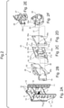
- FIG. 1 a simplified, exploded view of the components of a measuring device 42 for measuring forces and/or moments between a motorized vehicle and a trailer or attachment that is pulled or pushed by it and cannot be seen.
- Figure 1A a partial view of a motorized towing vehicle in the form of a tractor 1, at the rear of which a box-shaped standard hitch 8 is bolted, as will be explained later.
- Figure 1B shows schematically a first measuring device 42, the carrier 20 for sensor elements 22 is designed in the form of a measuring plate and is screwed by means of fastening screws 25 to a screw-on receptacle 6 in the form of a fastening plate on the tractor 1.
- a total of four sensor elements 22 are screwed to the carrier 20 designed as a measuring plate by means of countersunk fastening screws 24 via fastening rails 21 stored in between.
- the sensor elements 22 have free-standing tongues 22a, which are screwed to the standard trailer hitch 8 by means of fastening screws 23 via a further pair of fastening rails 21 .
- the sensor elements 22 are attached to the free-standing tongues 22a and are connected to an evaluation device 40 wirelessly or via the line connections shown.
- the evaluation device 40 is designed at least as an electronic circuit, but preferably as a microcomputer. It can be arranged on the carrier 20 designed as a measuring plate or on the tractor 1 .
- the zero point of a right-angled, three-axis coordinate system with coordinate axes X, Y, Z is in a wheel axis of rotation 3 of the rear wheel 2 of the tractor 1 drawn in, the Z axis running through a wheel contact point 5 of the rear wheel 2 at the level of the ground 4 .
- the standard trailer hitch 8 shown in a schematic side view is fastened to the tractor 1 by means of a tractor fastening plate 9 on the screw-on mount 6, between which the measuring device 42 mentioned is fastened.
- the sensor elements 22 are used to measure forces and can be designed as load cells, strain gauges or SAW elements (surface acoustic wave elements).
- the box-shaped standard hitch 8 shown has the already mentioned tractor fastening plate 9 and the same hole pattern 10 as the complementary fastening plate 6 on the tractor 1.
- On the side walls of the standard hitch 8 are parallel to one another a first locking rail 11 with a first locking groove 12 and a second Locking rail 13 attached to a second locking groove 14, the locking grooves 12, 14 are open facing each other.
- Bores 15 for locking means 19 in the form of locking pins are formed along the two locking grooves 12, 14, in which, for example, the locking pins 19 on a locking plate 18 of a standard open-end coupling 17 engage and fix this at a height H from the level of the ground 4.
- On a side wall of the standard hitch 8, a sensor 16 for detecting the height H of the standard hitch 17 is arranged.
- a sensor element 38 which measures the angle ⁇ between a drawbar 51 of a trailer or attachment and a straight line running through a central longitudinal axis of the tractor at height H in the X direction in a horizontal transverse plane 37 at height H of standard coupling 17.
- a further sensor element 39 for measuring an angle ⁇ vertically upwards or downwards between the drawbar 51 of a trailer or attachment and a horizontal transverse plane at height H in the X-direction.
- Said sensor elements 16, 38, 39 are also connected to the evaluation device 40 wirelessly or via the cables that are shown but not further identified. Therefore, the evaluation device 40 can use known algorithms to calculate both the forces Fx, Fy, Fz acting on the measuring device 20 and the corresponding moments Mx, My, Mz from the signals of the sensor elements 16, 22, 38, 39 according to size and direction as well as an forward a driving status management system.
- This driving state management system can derive unstable driving situations from the signals of the sensor elements 16, 22, 38, 39 and initiate countermeasures. It is also possible, from the signals of the sensor elements 16, 22, 38, 39, to coordinate the braking effect of the tractor 1 and the trailer or the attachment.
- the driving status management system is designed, for example, as a computer program and is stored in a separate microcomputer or in evaluation device 40 as software.
- the measuring device 42 can be installed as a module package both between the tractor 1 and the standard hitch 8 and can also be inserted with the carrier 20 designed as a measuring plate into the locking grooves 12, 14 of the standard hitch 8 and fixed therein at the mentioned height H, whereby according to a standard hitch 27 in the form of a jaw coupling Figure 2E is then screwed to the carrier 20 with its screw-on plate 28 .
- the screw-on plate 28 of the standard hitch 27 has a congruent standard hole pattern 28a like the carrier 20.
- FIG. 1C Visible PTO shaft 7 can only be used to drive ancillary units if it is not blocked by the measuring device 42. If necessary, the carrier 20 in the form of a measuring plate has a passage opening for the power take-off shaft 7 .
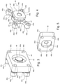
- a second embodiment of a measuring device 43 according to the invention is in 2 shown, whose Figure 2A shows the box-shaped standard hitch 8, which is also shown in Figure 1C is shown.
- This measuring device 43 has a carrier 31 in the form of a measuring plate with a standard hole pattern 31a, which corresponds to a standard hole pattern 26a of threaded holes in a standard clutch carrier 26 is congruent.
- the standard coupling carrier 26 can be pushed into the locking grooves 12, 14 of the standard hitch 8 and fixed in the bores 15 of the standard hitch 8 by means of locking means 19 in the form of locking pins on the standard coupling carrier 26.
- the carrier 31 in the form of a measuring plate preferably integrally formed on this radial spokes 32 which are arranged in a plane at an angle of 90 ° to each other. Free spaces 32a are thus formed between the radial spokes 32 and the support 31 in order to allow the radial spokes 32 to deform in the direction of the horizontal transverse plane 37 .
- the spokes 32 are connected radially on the inside to a central cylindrical hub 33, the axially protruding area 33a of which is preferably connected to an adapter plate 35 by means of a welded seam 33b in a materially bonded manner.
- the carrier 31 in the form of a measuring plate has a standard hole pattern 31a that is congruent with the standard hole pattern 26a on the standard coupling carrier 26 .
- the adapter plate 35 also has the same standard hole pattern 35a.
- Sensor elements 34 in the form of load cells, strain gauges or SAW elements are attached to the radial spokes 32 as force sensors 1 illustrated manner are connected to the evaluation device 40 wirelessly or via cable.
- the measured values determined by the sensor elements 34 can also be transmitted by radio via a relevant transmitter which is connected to an antenna 52 which is arranged on the upper side of the standard coupling carrier 26 .
- the carrier 31 in the form of a measuring plate is, together with the adapter plate 35, with which the axially projecting area 33a of the central, cylindrical hub 33 is coupled in a form-fitting or material-locking manner, between a screw-on plate 28 on a standard open-end coupling 27 or a screw-on plate 30 on a Standard ball hitch 29 and a standard clutch carrier 26 with prestressing of the spokes 32 clamped.
- the prestressing of the spokes 32 is applied by means of expansion bolts 36 arranged between the screw-on plate 28 , 30 of a standard trailer coupling 27 , 29 and the standard coupling carrier 26 .
- the screw-on plates 28, 30 of the standard trailer hitch 27 and the standard ball head coupling 29 each have a congruent standard hole pattern 28a, 30a for the passage of expansion screws 36.
- a pulling force applied to the standard hitch 27 causes the adapter plate 35 and thus the central, cylindrical hub 33 to move.
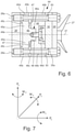
- This causes a corresponding relaxation of the radial spokes 32, which can also be detected by the sensor elements 34 and, due to the arrangement of the four radial spokes 32 offset by 90°, results in signals which, viewed together by a corresponding algorithm of the evaluation device 40, produce values for the applied forces Fx , Fx, Fz in X, Y, Z directions and the corresponding moments Mx, My, Mz, as shown in 7 is shown.
- the third embodiment variant of the measuring device 44 shown has a carrier 45 in the form of a measuring cross with two measuring arms 45a spaced apart by 60° or 120° from one another, the free ends of which have eyes 45b with through-holes 45d, and which are provided with projections 45c at the free ends , whose function is related to 6 is explained.
- the carrier 45 in the form of a measuring cross is provided with a central hub 46 which is essentially cylindrical but is provided with flattened areas 46b on a region 46a which protrudes axially on one side.
- This axially protruding area 46a with its flat areas 46b can be inserted into a non-circular depression 48c complementary to the hub 46 in a base plate 48, whereby the carrier 45 in the form of a measuring cross is secured against the base plate 48 against twisting.
- the non-round depression 48c of the base plate 48 ends axially on a wall element 48d with a central through hole 48e for an in 3 shown fastening screw 49, which is screwed into a threaded hole 46c in the central hub 46 of the carrier 45 in the form of a caliper.
- the base plate 48 On its rear side remote from the measuring cross, the base plate 48 has a cylindrical depression 48b, into which the head of the fastening screw 49 can be countersunk.
- the base plate 48 has four through bores 48b for passing through the already mentioned expansion bolts 50, which are also passed through the through bores 45d of the carrier 45 and ultimately screwed into the threaded bores 26a of the standard coupling carrier 26, which in 6 is clearly recognizable.
- sensor elements 47 in the form of load cells, strain gauges or SAW elements are arranged as force sensors on the measuring arms 45a and correspondingly 1 connected wirelessly or via cable, like the other sensor elements, to the evaluation device 40.
- the measuring device 44 is a module package consisting of the screw-on plate 28, 30, the standard hitch 27, 29, the adapter plate 35, the base plate 48, the carrier 45 in the form of a measuring cross and the standard coupling carrier 26, which are braced against one another by means of expansion bolts 50, on one standard trailer hitch 8 attached to the motorized vehicle 1 in a height-adjustable manner.
Landscapes
- Engineering & Computer Science (AREA)
- Mechanical Engineering (AREA)
- Physics & Mathematics (AREA)
- General Physics & Mathematics (AREA)
- Transportation (AREA)
- Life Sciences & Earth Sciences (AREA)
- Chemical & Material Sciences (AREA)
- Environmental Sciences (AREA)
- Soil Sciences (AREA)
- Analytical Chemistry (AREA)
- Combustion & Propulsion (AREA)
- Zoology (AREA)
- Fluid Mechanics (AREA)
- Acoustics & Sound (AREA)
- Force Measurement Appropriate To Specific Purposes (AREA)
Description
- Die Erfindung betrifft eine Messeinrichtung zum Messen von Kräften und/oder Momenten zwischen einem motorisierten Fahrzeug und einem davon gezogenen oder geschobenen Anhänger oder Anbaugerät.
- Aus der
EP 2 280 263 A2 ,US 2009/032273 A1 und derUS 2018/001720 A1 sind Vorrichtungen zur Bestimmung einer Anhängerlast bekannt. - Aus der
EP 2 893 793 B1 ist ein Zugkraftmesssystem bekannt, welches in einem Anhängebock an einem Traktor integriert ist. Der Anhängebock ist dazu ausgelegt, an einem Heckrahmen eines Ackerschleppers befestigt zu werden und weist linke und rechte Zugverbindungsstützen auf, wobei die linken und rechten Zugverbindungsstützen jeweils eine entsprechende linke und rechte Zugverbindung mit einer entsprechenden linken und rechten Seite des Anhängebocks koppeln. Es werden nur horizontale Zugkräfte, die von den linken und rechten Zugverbindungen auf die linken und rechten Zugverbindungsstützen ausgeübt werden, mechanisch summiert. Ein in einem Gehäuse, geschützt zwischen den Zugverbindungen angeordneter Zugkraft-Messwandler generiert daraus ein eindimensionales Zugkraftsignal. Der Anhängebock ist kompliziert aufgebaut, und der Zugkraft-Messwandler lässt sich nur mit diesem Anhängebock verwenden. Das Zugkraftmesssystem ist nicht dazu geeignet, Kräfte und/oder Momente zwischen einem motorisierten Fahrzeug und einem davon gezogenen oder geschobenen Anhänger oder Anbaugerät nach Größe und Richtung zu generieren und gegebenenfalls anzuzeigen. - Vor diesem Hintergrund lag der Erfindung die Aufgabe zugrunde, Koppelkräfte und Koppeldrehmomente am Kupplungspunkt zwischen einem motorisierten Fahrzeug, insbesondere einem Traktor, und einem Anhänger oder Anbaugerät während des Fahrens in drei Dimensionen zu messen, ohne dass dafür besondere Einrichtungen am Anhänger oder Anbaugerät vorgesehen werden müssen.
- Gelöst wird diese Aufgabe durch eine Messeinrichtung, welche die Merkmale des Anspruchs 1 oder 2 aufweist. Vorteilhafte Weiterbildungen sind in den abhängigen Ansprüchen genannt.
- Demnach betrifft die Erfindung eine Messeinrichtung zum Messen von Kräften und/oder Momenten zwischen einem motorisierten Fahrzeug und einem davon gezogenen oder geschobenen Anhänger oder Anbaugerät.
- Erfindungsgemäß ist vorgesehen, dass die Messeinrichtung wenigstens drei an einem Träger quer zu einer gedachten Längsachse des motorisierten Fahrzeugs sowie zueinander beabstandet angeordnete Sensorelemente aufweist, wobei die Messeinrichtung in einem Kupplungsbereich zwischen dem motorisierten Fahrzeug und dem gezogenen oder geschobenen Anhänger oder Anbaugerät angeordnet ist, und wobei die Sensorelemente zur Übertragung derer Messwerte mit einem Auswertegerät verbunden sind, welches dazu eingerichtet ist, diese Messwerte in Signale für Kraftanzeigen und/oder Momentenanzeigen nach Größe und Richtung umzuwandeln.
- Diese Messeinrichtung befindet sich grundsätzlich im Bereich des motorisierten Fahrzeugs, so dass an einem Anhänger oder Anbaugerät oder deren Kupplungsvorrichtungen keine Veränderungen vorgenommen zu werden brauchen. Aufgrund der in allen drei Raumkoordinaten ermittelbaren Messwerte in Form von Kräften und/oder Momenten nach Betrag und Richtung ist es in Weiterbildung der Erfindung vorgesehen, das erwähnte Auswertegerät in Datenverbindung mit einem Fahrzeugzustand-Managementsystem zu bringen, das dazu eingerichtet ist, aus den Messwerten der Sensorelemente instabile Fahrsituationen zu erkennen und Gegensteuermaßnahmen einzuleiten. Das Fahrzeugzustand-Managementsystem ist hierzu vorzugsweise als ein Mikrocomputer ausgebildet, welcher zur Durchführung von Gegensteuermaßnahmen mit einer geeigneten Software ausgestattet ist sowie mit geeigneten Aktuatoren und/oder elektromagnetischen Steuerventilen zur Betätigung derselben verbunden ist.
- Des Weiteren ist das Fahrzeugzustand-Managementsystem in Weiterbildung der Erfindung so eingerichtet, dass es in der Lage ist, aus den Messwerten der Sensorelemente Steuersignale für Aktuatoren zur Bewirkung einer Abstimmung der Bremswirkung des motorisierten Fahrzeugs und des Anhängers oder des Anhängegeräts aufeinander zu erzeugen.
- Gemäß der ersten Ausführung der Erfindung ist vorgesehen, dass die Messeinrichtung als Modulpaket an einem Standard-Anhängebock am motorisierten Fahrzeug montierbar ist sowie mittels eines am Standard-Anhängebock angeordneten Kupplungsträgers mit einer Standard-Anhängevorrichtung, wie etwa eine Standard-Maulkupplung oder eine Standard-Kugelkopfkupplung, verschraubt ist.
- Gemäß der zweiten Ausführung der Erfindung ist vorgesehen, dass die Messeinrichtung als Modulpaket zwischen einer Anschraubaufnahme am motorisierten Fahrzeug für einen Standard-Anhängebock und diesem Standard-Anhängebock montiert ist, und dass eine Standard-Anhängevorrichtung, wie etwa eine Standard-Maulkupplung oder eine Standard-Kugelkopfkupplung, direkt am Standard-Anhängebock befestigt ist.
- Vorzugsweise ist diese Standard-Anhängevorrichtung am Standard-Anhängebock lösbar und höhenverstellbar befestigt.
- Besonders vorteilhaft ist es, wenn auch der Kupplungsträger am Standard-Anhängebock lösbar und höhenverstellbar befestigt ist.
- Gemäß einer ersten vorteilhaften Ausführungsform der Messeinrichtung kann vorgesehen sein, dass vier Sensorelemente in Form von Wägezellen, Dehnungsmessstreifen oder SAW-Elementen (Surface-Acoustic-Wave-Elemente) als Kraftsensoren an dem messplattenförmigen Träger beabstandet im Quadrat oder im Rechteck angeordnet sind, dass die vier Sensorelemente einerseits über den messplattenförmigen Träger an einer Anschraubaufnahme in Form einer Befestigungsplatte am motorisierten Fahrzeug befestigt sind und andererseits mit dem Standard-Anhängebock in Wirkverbindung sind, um die durch eine Beanspruchung des Standard-Anhängebocks durch die Last des gezogenen oder geschobenen Anhängers oder des Anbaugeräts für das Auswertegerät bestimmte Signale zu generieren.
- Durch die Wirkverbindung zwischen dem Standard-Anhängebock und der Messplatte werden die vier Sensorelemente durch die Last des gezogenen oder geschobenen Anhängers oder des Anbaugeräts abhängig von Größe und Richtung der Beanspruchungen des Standard-Anhängebocks verformt. Aus den Signalen der Sensorelemente lassen sich mittels bekannter Algorithmen die Kräften Fx, Fy, Fz in X-, Y- und Z-Richtung eines rechtwinkeligen Koordinatensystems berechnen, ebenso wie die auftretenden Momente Mx, My und MZ. Diese Kräfte und Momente sind abhängig von der Höhe der Standard-Anhängevorrichtung über dem Niveau des Erdbodens und von einem Winkel a, den eine Deichsel eines Anhängers oder eines Anbaugeräts in einer waagerechten Querebene gegenüber dem motorisierten Fahrzeug einnimmt, und ebenso von einem Winkel ß, den die Deichsel des Anhängers oder des Anbaugeräts gegenüber der waagerechten Querebene des motorisierten Fahrzeugs vertikal nach oben oder unten einnimmt.
- Gemäß einer zweiten vorteilhaften Ausführungsform der erfindungsgemäßen Messeinrichtung ist vorgesehen, dass vier Sensorelemente in Form von Wägezellen, Dehnungsmessstreifen oder SAW-Elementen als Kraftsensoren an vier um etwa 90° gegeneinander versetzten, sich radial von einer zentralen, zylindrischen Nabe erstreckenden Speichen angeordnet sind, dass die Speichen kraft-, form- oder stoffschlüssig mit einem Träger in Form einer Messplatte gekoppelt sind, wobei dieser Träger in Form einer Messplatte zusammen mit einer Adapterplatte, mit welcher die zentrale, zylindrische Nabe form- oder stoffschlüssig gekoppelt ist, zwischen einer Anschraubplatte einer Standard-Anhängekupplung und einem Standard-Kupplungsträger eingespannt ist.
- Hierbei kann eine Vorspannung auf die Speichen über den axial vorstehenden Bereich der zylindrischen Nabe mittels zwischen der Anschraubplatte einer Standard-Anhängekupplung und dem Standard-Kupplungsträger angeordneten Dehnschrauben aufgebracht werden. Hierzu ist vorgesehen, dass in dem Träger in Form einer Messplatte eine dem Standard-Kupplungsträger zugewandte, die Speichen frei gebende und deren Verformung beim Aufbringen der Vorspannung mittels der Dehnschrauben ermöglichende Ausnehmung ausgebildet ist.
- Auch in diesem Fall kann die Messeinrichtung als Modulpaket ausgebildet sein, welche aus der Anschraubplatte der Standard-Anhängevorrichtung, der Adapterplatte, dem Träger in Form einer Messplatte und dem Standard-Kupplungsträger besteht, und welche mittels Dehnschrauben gegeneinander verspannt sind. Dieses Modulpaket ist an einem am motorisierten Fahrzeug befestigten Standard-Anhängebock bevorzugt höhenverstellbar anbringbar ausgebildet.
- Es ist ersichtlich, dass an einem Standard-Anhängebock unterschiedliche Standard-Anhängevorrichtungen angebracht werden können, die sich durch das geschilderte vertikale Führungssystem am Anhängebock in ihrer Höhe einstellen lassen.
- Die Übertragung der Signale der Sensorelemente zum motorisierten Fahrzeug kann über eine Kabelverbindung oder drahtlos, beispielsweise mittels W-LAN, erfolgen.
- Aufgrund des Aufbaus der erfindungsgemäßen Messeinrichtung lässt sich diese sowohl an landwirtschaftlichen Fahrzeugen, insbesondere Ackerschlepper, als auch an Straßenfahrzeugen verwenden. Die verschiedenen Standard-Anhängevorrichtungen lassen sich modular austauschen, ohne dass an der Messeinrichtung etwas zu ändern wäre. Mit der erfindungsgemäßen Messeinrichtung lassen sich auch die Massen des motorisierten Fahrzeugs und des Anhängers oder Anbaugeräts bestimmen, wodurch sich die Bremswirkungen von motorisierten Fahrzeugen und Anhänger oder Anbaugeräten verbessert abstimmen lassen.
- Die Erfindung wird nachstehend anhand mehrerer, in der beigefügten Zeichnung dargestellter Ausführungsbeispiele weiter erläutert. In der Zeichnung zeigt
-
Fig. 1 eine vereinfachte, auseinander gezogene Darstellung der Bauteile einer Messeinrichtung zum Messen von Kräften und/oder Momenten zwischen einem motorisierten Fahrzeug und einem davon gezogenen oder geschobenen Anhänger oder Anbaugerät, wovon -
Fig. 1A eine teilweise Ansicht eines motorisierten Fahrzeugs in Form eines Traktors mit einer schematischen Seitenansicht der Messeinrichtung gemäßFig. 1 zeigt, -
Fig. 1B eine auseinander gezogene isometrische Darstellung der Messeinrichtung gemäßFig. 1A zeigt, -
Fig. 1C eine isometrische Darstellung eines kastenförmigen Standard-Anhängebocks für einen Traktor zeigt, -
Fig. 1D eine schematische isometrische Darstellung einer Standard-Anhängevorrichtung in Form einer Maulkupplung zeigt, und bei der -
Fig. 2 eine vereinfachte, auseinander gezogene isometrische Darstellung der Bauelemente einer erfindungsgemäßen Messeinrichtung gemäß einer zweiten Ausführungsform zeigt, wovon, -
Fig. 2A eine isometrische Darstellung eines kastenförmigen Standard-Anhängebocks für einen Traktor zeigt, -
Fig. 2B eine isometrische Darstellung eines Standard-Kupplungsträgers mit Verriegelungsmitteln zeigt, -
Fig. 2C eine isometrische Darstellung einer Messeinrichtung an einem Träger in Form einer Messplatte mit einer Speichenradgeometrie gemäßFig. 2 zeigt, -
Fig. 2D eine isometrische Darstellung einer Adapterplatte zeigt, -
Fig. 2E eine isometrische Darstellung einer Standard-Maulkupplung mit Standard-Anschraubplatte zeigt, -
Fig. 2F eine dazu alternative isometrische Darstellung einer Standard-Kugelkopfkupplung mit Anschraubplatte zeigt, -
Fig. 2G eine Schnittansicht der Messeinrichtung gemäßFig. 2A mit den Elementen gemäß denFiguren 2B bis 2E zeigt, und bei der -
Fig. 3 eine isometrische Darstellung einer bevorzugten Ausführungsform der erfindungsgemäßen Messeinrichtung mit einem Messkreuz gemäßFig. 4 zeigt, -
Fig. 4 eine isometrische Darstellung eines mit einer Basisplatte zu verspannenden Messkreuzes gemäßFig. 3 zeigt, -
Fig. 5 eine isometrische Rückansicht der Basisplatte gemäßFig. 4 zeigt, -
Fig. 6 eine Schnittansicht der zusammengebauten Messeinrichtung gemäß denFiguren 3 bis 5 zeigt, und -
Fig. 7 ein rechtwinkliges, dreidimensionales Koordinatenkreuz mit eingezeichneten Kräften Fx, Fy, Fz und Momenten Mx, My, Mz zeigt. - Demnach zeigt
Fig. 1 eine vereinfachte, auseinander gezogene Darstellung der Bauteile einer Messeinrichtung 42 zum Messen von Kräften und/oder Momenten zwischen einem motorisierten Fahrzeug und einem davon gezogenen oder geschobenen, nicht erkennbaren Anhänger oder Anbaugerät. Im Detail zeigtFig. 1A eine Teilansicht eines motorisierten Zugfahrzeugs in Form eines Traktors 1, an dessen Heck ein kastenförmiger Standard-Anhängebock 8 angeschraubt ist, wie später noch erläutert wird. -
Fig. 1B zeigt schematisch eine erste Messeinrichtung 42, deren Träger 20 für Sensorelemente 22 in Form einer Messplatte ausgebildet ist und mittels Befestigungsschrauben 25 an einer Anschraubaufnahme 6 in Form einer Befestigungsplatte am Traktor 1 verschraubt ist. An dem als Messplatte ausgebildeten Träger 20 sind insgesamt vier Sensorelemente 22 mittels versenkter Befestigungsschrauben 24 über zwischengelagerte Befestigungsschienen 21 festschraubt. - Die Sensorelemente 22 weisen frei stehende Zungen 22a auf, die über ein weiteres Paar Befestigungsschienen 21 mittels Befestigungsschrauben 23 an dem Standard-Anhängebock 8 festschraubt sind. An den frei stehenden Zungen 22a sind die Sensorelemente 22 angebracht, die drahtlos oder über dargestellte Leitungsverbindungen mit einem Auswertegerät 40 verbunden sind. Das Auswertegerät 40 ist zumindest als eine elektronische Schaltung jedoch vorzugsweise als Mikrocomputer ausgebildet. Es kann an dem als Messplatte ausgebildeten Träger 20 oder am Traktor 1 angeordnet sein.
- In einer Raddrehachse 3 des Hinterrades 2 des Traktors 1 ist der Nullpunkt eines rechtwinkligen, dreiachsigen Koordinatensystems mit Koordinatenachsen X, Y, Z eingezeichnet, wobei die Z -Achse durch einen Radaufstandspunkt 5 des Hinterrades 2 auf dem Niveau des Erdbodens 4 verläuft.
- Der in
Fig. 1A in einer schematischen Seitenansicht dargestellte Standard-Anhängebock 8 ist am Traktor 1 mittels einer Traktorbefestigungsplatte 9 an der Anschraubaufnahme 6 befestigt, zwischen denen die erwähnte Messeinrichtung 42 befestigt ist. Die Sensorelemente 22 dienen der Kräftemessung und können als Wägezellen, Dehnungsmessstreifen oder SAW-Elemente (Surface-Acoustic-Wave-Elemente) ausgebildet sein. - Der in
Fig. 1C dargestellte kastenförmige Standard-Anhängebock 8 weist die bereits erwähnte Traktorbefestigungsplatte 9 sowie das gleiche Bohrungsschema 10 auf wie die dazu komplementäre Befestigungsplatte 6 am Traktor 1. An Seitenwänden des Standard-Anhängebocks 8 sind parallel zueinander eine erste Rastschiene 11 mit einer ersten Rastnut 12 und eine zweite Rastschiene 13 mit einer zweiten Rastnut 14 angebracht, deren Rastnuten 12, 14 zueinander weisend geöffnet sind. Entlang der beiden Rastnuten 12, 14 sind Bohrungen 15 für Verriegelungsmittel 19 in Form von Rastzapfen ausgebildet, in die beispielsweise die Rastzapfen 19 an einer Rastplatte 18 einer Standard-Maulkupplung 17 eingreifen und diese in einer Höhe H vom Niveau des Erdbodens 4 fixieren. An einer Seitenwand des Standard-Anhängebocks 8 ist ein Sensor 16 zum Erkennen der Höhe H der Standard-Kupplung 17 angeordnet. - Des Weiteren ist gemäß
Fig. 1D ein Sensorelement 38 vorhanden, welches in einer waagerechten Querebene 37 in der Höhe H der Standard-Kupplung 17 den Winkel α zwischen einer Deichsel 51 eines Anhängers oder Anbaugeräts und einer durch eine Mittellängsachse des Traktors in Höhe H in X-Richtung verlaufenden Geraden misst. Außerdem ist ein weiteres Sensorelement 39 zum Messen eines Winkels β nach vertikal oben oder unten zwischen der Deichsel 51 eines Anhängers oder Anbaugeräts und einer waagerechten Querebene in der Höhe H in X-Richtung vorhanden. - Die genannten Sensorelemente 16, 38, 39 sind ebenfalls drahtlos oder über die dargestellten, aber nicht weiter bezeichneten Kabel mit dem Auswertegerät 40 verbunden. Daher kann das Auswertegerät 40 mittels bekannter Algorithmen sowohl die auf die Messeinrichtung 20 einwirkenden Kräfte Fx, Fy, Fz als auch die entsprechenden Momente Mx, My, Mz aus den Signalen der Sensorelemente 16, 22, 38, 39 nach Größe und Richtung berechnen sowie an ein Fahrzustand-Managementsystem weiterleiten. Dieses Fahrzustand-Managementsystem kann aus den Signalen der Sensorelemente 16, 22, 38, 39 instabile Fahrsituationen ableitend erkennen und Gegensteuermaßnahmen einleiten. Ebenso ist es möglich, aus den Signalen der Sensorelemente 16, 22, 38, 39 eine Abstimmung der Bremswirkung des Traktors 1 und des Anhängers oder des Anbaugeräts vorzunehmen. Das Fahrzustand-Managementsystem ist beispielswiese als ein Computerprogramm ausgebildet und in einem gesonderten Mikrocomputer oder in dem Auswertegerät 40 als Software abgespeichert.
- Die Messeinrichtung 42 lässt sich als Modulpaket sowohl zwischen dem Traktor 1 und dem Standard-Anhängebock 8 montieren als auch mit dem als Messplatte ausgebildeten Träger 20 in die Rastnuten 12, 14 des Standard-Anhängebocks 8 einschieben und darin in der erwähnten Höhe H fixieren, wobei eine Standard-Anhängevorrichtung 27 in Form einer Maulkupplung gemäß
Fig. 2E mit ihrer Anschraubplatte 28 dann an dem Träger 20 verschraubt ist. Hierzu weist die Anschraubplatte 28 der Standard-Anhängevorrichtung 27 ein kongruentes Standard-Lochschema 28a auf wie der Träger 20. - Eine in
Fig. 1C sichtbare Zapfwelle 7 lässt sich für den Antrieb von Nebenaggregaten nur dann benutzen, wenn diese nicht durch die Messeinrichtung 42 versperrt ist. Gegebenenfalls weist der messplattenförmige Träger 20 eine Durchführungsöffnung für die Zapfwelle 7 auf. - Eine zweite Ausführungsform einer erfindungsgemäßen Messeinrichtung 43 ist in
Fig. 2 dargestellt, derenFig. 2A den kastenförmigen Standard-Anhängebock 8 zeigt, welcher auch inFig. 1C dargestellt ist. Diese Messeinrichtung 43 weist einen Träger 31 in Form einer Messplatte mit einem Standard-Lochschema 31a auf, das zu einem Standard-Lochschema 26a von Gewindebohrungen in einem Standard-Kupplungsträger 26 kongruent ist. Der Standard-Kupplungsträger 26 lässt sich wie bereits beschrieben in die Rastnuten 12, 14 des Standard-Anhängebocks 8 einschieben und mittels Verriegelungsmittel 19 in Form der Rastzapfen am Standard-Kupplungsträger 26 in den Bohrungen 15 des Standard-Anhängebocks 8 fixieren. - Wie
Fig. 2C erkennen lässt, weist der Träger 31 in Form einer Messplatte vorzugsweise einstückig an diesem ausgebildete radiale Speichen 32 auf, die in einer Ebene unter einem Winkel von 90° zueinander angeordnet sind. Zwischen den radialen Speichen 32 und dem Träger 31 sind somit Freiräume 32a ausgebildet, um es den radialen Speichen 32 zu erlauben, sich in Richtung der waagerechten Querebene 37 zu verformen. - Die Speichen 32 sind radial innen mit einer zentralen zylindrischen Nabe 33 verbunden, deren axial vorstehender Bereich 33a vorzugsweise mittels einer Schweißnaht 33b mit einer Adapterplatte 35 stoffschlüssig verbunden ist. Der Träger 31 in Form einer Messplatte weist wie erwähnt ein zu dem Standard-Lochbild 26a am Standard-Kupplungsträger 26 kongruentes Standard-Lochschema 31a auf. Ein ebensolches Standard-Lochschema 35a weist auch die Adapterplatte 35 auf.
- An den radialen Speichen 32 sind Sensorelemente 34 in Form von Wägezellen, Dehnungsmessstreifen oder SAW-Elementen als Kraftsensoren angebracht, die in der in
Fig. 1 dargestellten Weise mit dem Auswertegerät 40 drahtlos oder über Kabel verbunden sind. Die funktechnische Übertragung der ermittelten Messwerte der Sensorelemente 34 kann auch über einen diesbezüglichen Sender erfolgen, welcher mit einer Antenne 52 verbunden ist, die an der Oberseite des Standard-Kupplungsträgers 26 angeordnet ist. - Der Träger 31 in Form einer Messplatte ist zusammen mit der Adapterplatte 35, mit welcher der axial vorstehender Bereich 33a der zentralen, zylindrischen Nabe 33 form- oder stoffschlüssig gekoppelt ist, zwischen einer Anschraubplatte 28 an einer Standard-Maulkupplung 27 oder einer Anschraubplatte 30 an einer Standard-Kugelkopfkupplung 29 und einem Standard-Kupplungsträger 26 mit Vorspannung der Speichen 32 eingespannt.
- Die Vorspannung der Speichen 32 wird mittels zwischen der Anschraubplatte 28, 30 einer Standard-Anhängekupplung 27, 29 und dem Standard-Kupplungsträger 26 angeordneten Dehnschrauben 36 aufgebracht. Die Anschraubplatten 28, 30 der Standard-Anhängekupplung 27 und der Standard-Kugelkopfkupplung 29 weisen hierzu jeweils ein kongruentes Standard-Lochschema 28a, 30a zum Durchführen von Dehnschrauben 36 auf.
- Wie
Fig. 2G zeigt, sind in dem Träger 33 in Form einer Messplatte die Speichen 32 freigebende und deren Verformung beim Aufbringen der Vorspannung mittels der Dehnschrauben 36 ermöglichende Ausnehmung beziehungsweise Freiräume 33c ausgebildet. Hierdurch kann eine Verformung der Speichen 32 in Richtung des Standard-Kupplungsträgers 26 durch eine auf die Standard-Anhängekupplung 27 wirkende Druckkraft hervorgerufen werden, so dass diese und die von den Dehnschrauben 36 aufgebrachte Vorspannung mittels der Sensorelemente 34 messbar ist. - Umgekehrt wird durch eine auf die Standard-Anhängekupplung 27 aufgebrachte Zugkraft eine Bewegung der Adapterplatte 35 und damit der zentralen, zylindrischen Nabe 33 hervorgerufen. Dies bewirkt eine entsprechende Entspannung der radialen Speichen 32, die ebenfalls mittels der Sensorelemente 34 erfassbar ist und aufgrund der um 90° versetzten Anordnung der vier radialen Speichen 32 Signale ergibt, welche zusammen betrachtet durch einen entsprechenden Algorithmus des Auswertegeräts 40 Werte für die aufgebrachten Kräfte Fx, Fx, Fz in X-, Y-, Z-Richtung sowie die entsprechenden Momente Mx, My, Mz ergibt, wie dies in
Fig. 7 dargestellt ist. - Die in den
Figuren 3 bis 6 dargestellte dritte Ausführungsvariante der Messeinrichtung 44 weist einen Träger 45 in Form eines Messkreuzes mit je zwei um 60° beziehungsweise 120° zueinander beabstandete Messarme 45a auf, deren freie Enden Augen 45b mit Durchgangsbohrungen 45d aufweisen, und die an den freien Enden mit Vorsprüngen 45c versehen sind, deren Funktion im Zusammenhang mitFig. 6 erläutert wird. Der Träger 45 in Form eines Messkreuzes ist mit einer zentralen Nabe 46 versehen, die im Wesentlichen zylindrisch ausgebildet ist, jedoch an einem einseitig axial vorstehenden Bereich 46a mit Anflächungen 46b versehen ist. Dieser axial vorstehende Bereich 46a mit seinen Anflächungen 46b lässt sich in eine zur Nabe 46 komplementäre, unrunde Vertiefung 48c in einer Basisplatte 48 einfügen, wodurch der Träger 45 in Form eines Messkreuzes gegenüber der Basisplatte 48 gegen ein Verdrehen gesichert ist. Die unrunde Vertiefung 48c der Basisplatte 48 endet axial an einem Wandelement 48d mit einer zentralen Durchgangsbohrung 48e für eine inFig. 3 dargestellte Befestigungsschraube 49, die in eine Gewindebohrung 46c in der zentralen Nabe 46 des Trägers 45 in Form eines Messkreuzes eingeschraubt ist. - Auf ihrer messkreuzfernen Rückseite weist die Basisplatte 48 eine zylindrische Vertiefung 48b auf, in welche der Kopf der Befestigungsschraube 49 versenkbar ist. Au-ßerdem zeigen die
Figuren 3 und 5 deutlich, dass die Basisplatte 48 vier Durchgangsbohrungen 48b zur Durchführung der bereits erwähnten Dehnschrauben 50 aufweist, welche auch durch die Durchgangsbohrungen 45d des Trägers 45 hindurchgeführt und letztlich in den Gewindebohrungen 26a des Standard-Kupplungsträgers 26 eingeschraubt sind, welches inFig. 6 gut erkennbar ist. - Zwischen den Augen 45b an den Enden der vier Messarme 45a und der zentralen Nabe 46 des Trägers 45 sind an den Messarmen 45a jeweils Sensorelemente 47 in Form von Wägezellen, Dehnungsmessstreifen oder SAW-Elementen als Kraftsensoren angeordnet sowie entsprechend
Fig. 1 drahtlos oder über Kabel, wie auch die anderen Sensorelemente, mit dem Auswertegerät 40 verbunden. - Auch die Messeinrichtung 44 gemäß den
Figuren 3 bis 6 ist als Modulpaket aus der Anschraubplatte 28, 30 der Standard-Anhängevorrichtung 27, 29, der Adapterplatte 35, der Basisplatte 48, dem Träger 45 in Form eines Messkreuzes und dem Standard-Kupplungsträger 26, die mittels der Dehnschrauben 50 gegeneinander verspannt sind, an einem am motorisierten Fahrzeug 1 befestigten Standard-Anhängebock 8 höhenverstellbar anbringbar. -
- 1
- Motorisiertes Fahrzeug (Traktor)
- 2
- Hinterrad
- 3
- Raddrehachse
- 4
- Niveau des Erdbodens
- 5
- Radaufstandspunkt
- 6
- Anschraubaufnahme (Befestigungsplatte am Traktor)
- 7
- Zapfwelle
- 8
- Standard-Anhängebock, kastenförmig
- 9
- Traktorbefestigungsplatte am Anhängebock
- 10
- Bohrungsschema am Standard-Anhängebock
- 11
- Erste Rastschiene am Standard-Anhängebock
- 12
- Erste Rastnut
- 13
- Zweite Rastschiene am Standard-Anhängebock
- 14
- Zweite Rastnut
- 15
- Bohrungen für Verriegelungsmittel in Rastschiene
- 16
- Sensorelement zum Erkennen der Kupplungshöhe H
- 17
- Standard-Maulkupplung
- 18
- Rastplatte an der Maulkupplung
- 19
- Verriegelungsmittel (Rastzapfen)
- 20
- Träger in Form einer Messplatte
- 21
- Befestigungsschienen
- 22
- Sensorelemente
- 22a
- Freistehende Zungen der Sensorelemente 22
- 23
- Befestigungsschrauben
- 24
- Versenkte Befestigungsschrauben
- 25
- Befestigungsschrauben
- 26
- Standard-Kupplungsträger mit Verriegelungsmitteln
- 26a
- Standard-Lochschema von Gewindebohrungen am Kupplungsträger 26
- 27
- Standard-Maulkupplung
- 28
- Standard-Anschraubplatte an Maulkupplung 27
- 28a
- Standard-Lochschema von Durchgangsbohrungen in Anschraubplatte 28
- 29
- Standard-Kugelkopfkupplung
- 30
- Standard-Anschraubplatte an Kugelkopfkupplung 29
- 30a
- Standard-Lochschema von Durchgangsbohrungen der Anschraubplatte 30
- 31
- Träger in Form einer Messplatte
- 31a
- Standard-Lochschema von Durchgangsbohrungen im Träger 31
- 32
- Radiale Speichen an Träger 31
- 32a
- Freiraum zwischen Speichen 32
- 33
- Zentrale, zylindrische Nabe an Träger 31
- 33a
- Axial vorstehender Bereich der Nabe 33
- 33b
- Schweißnaht
- 33c
- Ausnehmung im Träger 31
- 34
- Sensorelemente an den Speichen
- 35
- Adapterplatte
- 35a
- Standard-Lochschema von Durchgangsbohrungen in Adapterplatte 35
- 36
- Dehnschrauben
- 37
- Waagerechte Querebene durch eine Längsachse des Traktors in Höhe H der Standard-Kupplung 17, in Richtung X-Achse
- 38
- Sensorelement zur Messung von Winkel α
- 39
- Sensorelement zur Messung von Winkel β
- 40
- Auswertegerät
- 42
- Erste Ausführungsform einer Messeinrichtung
- 43
- Zweite Ausführungsform einer Messeinrichtung
- 44
- Dritte Ausführungsform einer Messeinrichtung
- 45
- Träger in Form eines Messkreuzes
- 45a
- Messarme am Träger 45
- 45b
- Augen an den Messarmen 45a
- 45c
- Vorsprünge an den Augen 45b
- 45d
- Durchgangsbohrungen in den Augen 45b
- 46
- Zentrale Nabe des Trägers 45
- 46a
- Einseitig axial vorstehender Bereich der Nabe 46
- 46b
- Anflächungen an der Nabe 46
- 46c
- Gewindebohrung in der Nabe 46
- 47
- Sensorelemente an den Messarmen 45a
- 48
- Basisplatte
- 48a
- Zylindrische Vertiefung in der Basisplatte 48
- 48b
- Durchgangsbohrungen in der Basisplatte 48
- 48c
- Unrunde Vertiefung in der Basisplatte 48
- 48d
- Wandelement der Basisplatte 48
- 48e
- Zentrale Bohrung in der Basisplatte 48
- 49
- Befestigungsschraube
- 50
- Dehnschrauben
- 51
- Deichsel des Anhängers oder des Anhängegeräts
- 52
- Antenne
- H
- Abstand einer Standard-Anhängekupplung am Traktor vom Niveau des Erdbodens
- X, Y, Z
- Koordinatenachsen
- α
- Winkel zwischen einer Deichsel eines Anhängers oder Anbaugeräts und einer durch eine Mittellängsachse des Traktors in Höhe H in X-Richtung verlaufenden Geraden
- β
- Winkel nach oben oder unten zwischen einer Deichsel eines Anhängers oder Anbaugeräts und einer waagerechten Querebene in Höhe H in X-Richtung
Claims (11)
- Messeinrichtung (42, 43, 44) zum Messen von Kräften und/oder Momenten zwischen einem motorisierten Fahrzeug (1) und einem davon gezogenen oder geschobenen Anhänger oder Anbaugerät,wobei die Messeinrichtung (42, 43, 44) wenigstens drei an einem Träger (20, 31, 45) quer zu einer gedachten Längsachse des motorisierten Fahrzeugs (1) sowie zueinander beabstandet angeordnete Sensorelemente (22, 34, 47) aufweist,wobei die Messeinrichtung (42, 43, 44) in einem Kupplungsbereich zwischen dem motorisierten Fahrzeug (1) und dem gezogenen oder geschobenen Anhänger oder Anbaugerät angeordnet ist,und wobei die Sensorelemente (22, 34, 47) zur Übertragung derer Messwerte mit einem Auswertegerät (40) verbunden sind,welches dazu eingerichtet ist, diese Messwerte in Signale für Kraftanzeigen und/oder Momentenanzeigen nach Größe und Richtung umzuwandeln, dadurch gekennzeichnet,dass die Messeinrichtung (42, 43, 44) als Modulpaket an einem Standard-Anhängebock (8) am motorisierten Fahrzeug (1) montiert istsowie mittels eines am Standard-Anhängebock (8) angeordneten Kupplungsträgers (26) mit einer Standard-Anhängevorrichtung (17, 27, 29), wie eine Standard-Maulkupplung (17, 27) oder eine Standard-Kugelkopfkupplung (29), verschraubt ist.
- Messeinrichtung (42, 43, 44) zum Messen von Kräften und/oder Momenten zwischen einem motorisierten Fahrzeug (1) und einem davon gezogenen oder geschobenen Anhänger oder Anbaugerät,wobei die Messeinrichtung (42, 43, 44) wenigstens drei an einem Träger (20, 31, 45) quer zu einer gedachten Längsachse des motorisierten Fahrzeugs (1) sowie zueinander beabstandet angeordnete Sensorelemente (22, 34, 47) aufweist,wobei die Messeinrichtung (42, 43, 44) in einem Kupplungsbereich zwischen dem motorisierten Fahrzeug (1) und dem gezogenen oder geschobenen Anhänger oder Anbaugerät angeordnet ist,und wobei die Sensorelemente (22, 34, 47) zur Übertragung derer Messwerte mit einem Auswertegerät (40) verbunden sind,welches dazu eingerichtet ist, diese Messwerte in Signale für Kraftanzeigen und/oder Momentenanzeigen nach Größe und Richtung umzuwandeln, dadurch gekennzeichnet,dass die Messeinrichtung (42, 43, 44) als Modulpaket zwischen einer Anschraubaufnahme (6) am motorisierten Fahrzeug (1) für einen Standard-Anhängebock (8) und diesem Standard-Anhängebock (8) montiert ist,und dass eine Standard-Anhängevorrichtung (17, 27, 29), wie eine Standard-Maulkupplung (17, 27) oder eine Standard-Kugelkopfkupplung (29), direkt am Standard-Anhängebock (8) befestigt ist.
- Messeinrichtung (42, 43, 44) nach Anspruch 1 oder 2, dadurch gekennzeichnet, dass das Auswertegerät (40) in Datenverbindung mit einem Fahrzustand-Managementsystem ist,
welches dazu eingerichtet ist, aus den Messwerten der Sensorelemente (22, 34, 47) instabile Fahrsituationen zu erkennen und Gegensteuermaßnahmen einzuleiten. - Messeinrichtung (42, 43, 44) nach Anspruch 3, dadurch gekennzeichnet,dass das Fahrzustand-Managementsystem dazu eingerichtet ist,aus den Messwerten der Sensorelemente (22, 34,47) Steuersignale für Aktuatoren zur Bewirkung einer Abstimmung der Bremswirkung des motorisierten Fahrzeugs (1) und des Anhängers oder des Anhängegeräts aufeinander zu erzeugen.
- Messeinrichtung (42, 43, 44) nach Anspruch 2, dadurch gekennzeichnet,
dass die Standard-Anhängevorrichtung (17, 27, 29) am Standard-Anhängebock (8) lösbar und höhenverstellbar befestigt ist. - Messeinrichtung (42, 43, 44) nach Anspruch 1, dadurch gekennzeichnet,
dass der Kupplungsträger (26) am Standard-Anhängebock (8) lösbar und höhenverstellbar befestigt ist. - Messeinrichtung (42) nach einem der Ansprüche 1 bis 6, dadurch gekennzeichnet, dass vier Sensorelemente (22) in Form von Wägezellen, Dehnungsmessstreifen oder SAW-Elementen als Kraftsensoren an dem messplattenförmigen Träger (20) beabstandet im Quadrat oder im Rechteck angeordnet sind,dass die vier Sensorelemente (22) einerseits über den messplattenförmigen Träger (20) an einer Anschraubaufnahme (6) in Form einer Befestigungsplatte am motorisierten Fahrzeug (1) befestigt sind und andererseits mit dem Standard-Anhängebock (8) in Wirkverbindung sind,um die durch eine Beanspruchung des Standard-Anhängebocks (8) durch die Last des gezogenen oder geschobenen Anhängers oder des Anbaugeräts für das Auswertegerät (40) bestimmte Signale zu generieren.
- Messeinrichtung (43) nach einem der Ansprüche 1 bis 6, dadurch gekennzeichnet, dass vier Sensorelemente (34) in Form von Wägezellen, Dehnungsmessstreifen oder SAW-Elementen als Kraftsensoren an vier um etwa 90° gegeneinander versetzten, sich radial von einer zentralen, zylindrischen Nabe (33) erstreckenden Speichen (32) angeordnet sind,dass die Speichen (32) kraft-, form- oder stoffschlüssig mit einem Träger (31) in Form einer Messplatte gekoppelt sind,wobei dieser Träger (31) in Form einer Messplatte (31) zusammen mit einer Adapterplatte (35), mit welcher die zentrale, zylindrische Nabe (33) form- oder stoffschlüssig gekoppelt ist,zwischen einer Anschraubplatte (28, 30) einer Standard-Anhängekupplung (27, 29) und einem Standard-Kupplungsträger (26) eingespannt ist.
- Messeinrichtung (43) nach Anspruch 8, dadurch gekennzeichnet,
dass eine Vorspannung auf die Speichen (32) über einen axial vorstehenden Bereich (33a) der zylindrischen Nabe (33) mittels zwischen der Anschraubplatte (28, 30) einer Standard-Anhängekupplung (27, 29) und dem Standard-Kupplungsträger (26) angeordneten Dehnschrauben (36) aufgebracht wird. - Messeinrichtung (43) nach Anspruch 8 oder 9, dadurch gekennzeichnet,
dass in dem Träger (31) in Form einer Messplatte eine dem Standard-Kupplungsträger (26) zugewandte, die Speichen (32) frei gebende und deren Verformung beim Aufbringen der Vorspannung mittels der Dehnschrauben (36) ermöglichende Ausnehmung (33b) ausgebildet ist. - Messeinrichtung (43) nach einem der Ansprüche 8 bis 10, dadurch gekennzeichnet,
dass die Messeinrichtung (43) als Modulpaket, bestehend aus der Anschraubplatte (28, 30) der Standard-Anhängevorrichtung (27, 29), der Adapterplatte (35), dem Träger (31) in Form der Messplatte und dem Standard-Kupplungsträger (26), die mittels der Dehnschrauben (36) gegeneinander verspannt sind, an einem am motorisierten Fahrzeug (1) befestigten Standard-Anhängebock (8) höhenverstellbar anbringbar ausgebildet ist.
Applications Claiming Priority (1)
| Application Number | Priority Date | Filing Date | Title |
|---|---|---|---|
| DE102018106856.5A DE102018106856A1 (de) | 2018-03-22 | 2018-03-22 | Messeinrichtung zum Messen von Kräften und/oder Momenten zwischen einem motorisierten Fahrzeug und einem davon gezogenen oder geschobenen Anhänger oder Anbaugerät |
Publications (4)
| Publication Number | Publication Date |
|---|---|
| EP3553483A2 EP3553483A2 (de) | 2019-10-16 |
| EP3553483A3 EP3553483A3 (de) | 2020-02-26 |
| EP3553483B1 true EP3553483B1 (de) | 2022-02-09 |
| EP3553483B8 EP3553483B8 (de) | 2022-03-23 |
Family
ID=65818407
Family Applications (1)
| Application Number | Title | Priority Date | Filing Date |
|---|---|---|---|
| EP19163593.7A Active EP3553483B8 (de) | 2018-03-22 | 2019-03-19 | Messeinrichtung zum messen von kräften und/oder momenten zwischen einem motorisierten fahrzeug und einem davon gezogenen oder geschobenen anhänger oder anbaugerät |
Country Status (3)
| Country | Link |
|---|---|
| US (1) | US10871410B2 (de) |
| EP (1) | EP3553483B8 (de) |
| DE (1) | DE102018106856A1 (de) |
Families Citing this family (10)
| Publication number | Priority date | Publication date | Assignee | Title |
|---|---|---|---|---|
| DE102016108541A1 (de) * | 2016-05-09 | 2017-11-09 | Bosal Nederland B.V. | Vorrichtung zum Ziehen eines Anhängers und/oder Halten einer Lastenträgereinheit |
| DE102018209347A1 (de) * | 2018-06-12 | 2019-12-12 | Deere & Company | Halterahmen für einen Frontkraftheber |
| US12415486B2 (en) * | 2019-10-31 | 2025-09-16 | Deere & Company | Cart stability system |
| EP4281342B1 (de) | 2021-01-19 | 2025-02-05 | AGCO International GmbH | Anhängersteuergerät |
| US11964522B2 (en) * | 2021-03-15 | 2024-04-23 | Deere & Company | Implement attachment assembly and method of use |
| DE102021133762A1 (de) | 2021-12-17 | 2023-06-22 | Zf Cv Systems Global Gmbh | Kopplungsvorrichtung zum Koppeln eines Zugfahrzeugs mit einem Anhängefahrzeug |
| DE102021133763A1 (de) | 2021-12-17 | 2023-06-22 | Zf Cv Systems Global Gmbh | Verfahren zur Ladungsüberwachung eines Fahrzeuggespanns |
| DE102021133761A1 (de) | 2021-12-17 | 2023-06-22 | Zf Cv Systems Global Gmbh | Verfahren zur Steuerung von Sicherheitsfunktionen eines Fahrzeuggespanns |
| DE102021133758A1 (de) * | 2021-12-17 | 2023-06-22 | Zf Cv Systems Global Gmbh | Verfahren zur Traktionssteuerung eines Fahrzeugs oder eines Fahrzeuggespanns |
| DE102022213828A1 (de) | 2022-12-19 | 2024-06-20 | Zf Cv Systems Global Gmbh | Verfahren und Vorrichtung zur Überwachung der Betriebssicherheit eines Anhängefahrzeugs, welches an ein Zugfahrzeug angekoppelt ist |
Family Cites Families (23)
| Publication number | Priority date | Publication date | Assignee | Title |
|---|---|---|---|---|
| DE2752641A1 (de) * | 1977-11-25 | 1979-05-31 | Bosch Gmbh Robert | Deichselkraftregeleinrichtung |
| SE8400484D0 (sv) * | 1984-01-31 | 1984-01-31 | Slim Borgudd | Anordning for metning av dynamisk och statisk lastpakenning vid en draganordning for t ex drivorgan |
| US4573362A (en) * | 1984-07-09 | 1986-03-04 | Eaton Corporation | Multi-axis load transducer |
| US5149121A (en) * | 1987-08-05 | 1992-09-22 | Pfister Gbmh | Force measuring device |
| US4864874A (en) * | 1987-08-05 | 1989-09-12 | Pfister Gmbh | Force measuring device |
| DE3907763A1 (de) * | 1989-03-10 | 1990-09-27 | Bosch Gmbh Robert | Vorrichtung zum bestimmen der deichselkraefte eines anhaengers |
| SE464374B (sv) * | 1989-08-04 | 1991-04-15 | Siarr Sweden Ab | Kraftmaetaranordning foer maetning av vertikalkraftkomponenten verkande paa ett kopplingsdon mellan ett dragfordon och ett slaepfordon |
| DE3935479A1 (de) * | 1989-10-25 | 1991-05-02 | Pfister Gmbh | Anhaengerkupplung |
| US5213396A (en) * | 1990-12-06 | 1993-05-25 | Avery Larry L | Towed vehicle brake activation method and apparatus |
| EP0575634B1 (de) * | 1992-05-25 | 1996-10-09 | Hottinger Baldwin Messtechnik Gmbh | Drehmomentsensor |
| GB9302762D0 (en) * | 1993-02-11 | 1993-03-24 | Lucas Ind Plc | Improvements in draw-bar couplings for articulated vehicles |
| DE4419673C2 (de) * | 1994-06-07 | 1998-03-12 | Hottinger Messtechnik Baldwin | Anhängerkupplung mit einem Kraftaufnehmer |
| GB9907523D0 (en) * | 1999-04-01 | 1999-05-26 | Evans Kenneth S | Tow coupling sensor |
| GB2353340B (en) * | 1999-08-20 | 2003-11-05 | Vincent Roy Garvey | Trailer safety |
| KR100910972B1 (ko) * | 2002-12-07 | 2009-08-05 | 엘지전자 주식회사 | 대화형 광디스크 장치에서의 재생 제어방법 |
| DE102007036429A1 (de) * | 2007-08-02 | 2009-02-05 | Deere & Company, Moline | Steuerungssystem und Verfahren zum Betreiben eines Steuerungssystems zum Lenken eines an ein landwirtschafliches Nutzfahrzeug anagekoppelten Anbaugeräts |
| DE102009022343B4 (de) * | 2009-05-15 | 2016-04-28 | Brosa Ag | Kraftmesssystem zum Messen von Schub- bzw. Druckkräften, insbesondere bei Spreadern |
| DE102010004336A1 (de) * | 2009-07-30 | 2011-03-03 | Diemer, Andreas | Stützlastmessungsvorrichtung und Nachrüstverfahren für eine Fahrzeug-Anhängevorrichtung |
| US20130253814A1 (en) * | 2012-03-24 | 2013-09-26 | Alvin R. Wirthlin | System and Method for Gauging Safe Towing Parameters |
| US9550399B2 (en) * | 2012-12-21 | 2017-01-24 | Intelli-Hitch, Llc | Tow hitch with brake sensor system and method of use |
| DE202013008872U1 (de) * | 2013-10-05 | 2015-01-07 | Josef Scharmüller | Anhängebock für ein Zugfahrzeug |
| US9347844B2 (en) | 2013-12-19 | 2016-05-24 | Deere & Company | Three point hitch draft sensing system |
| AU2015227084B2 (en) * | 2014-03-05 | 2019-10-31 | Kevin Mcallister | Ball mount for measuring tongue weight of a trailer |
-
2018
- 2018-03-22 DE DE102018106856.5A patent/DE102018106856A1/de not_active Withdrawn
-
2019
- 2019-03-19 EP EP19163593.7A patent/EP3553483B8/de active Active
- 2019-03-22 US US16/361,502 patent/US10871410B2/en active Active
Also Published As
| Publication number | Publication date |
|---|---|
| EP3553483B8 (de) | 2022-03-23 |
| EP3553483A3 (de) | 2020-02-26 |
| US20190293506A1 (en) | 2019-09-26 |
| EP3553483A2 (de) | 2019-10-16 |
| US10871410B2 (en) | 2020-12-22 |
| DE102018106856A1 (de) | 2019-09-26 |
Similar Documents
| Publication | Publication Date | Title |
|---|---|---|
| EP3553483B1 (de) | Messeinrichtung zum messen von kräften und/oder momenten zwischen einem motorisierten fahrzeug und einem davon gezogenen oder geschobenen anhänger oder anbaugerät | |
| EP3553486A2 (de) | Messeinrichtung zum messen von kräften und/oder momenten zwischen einem motorisierten fahrzeug und einem davon gezogenen oder geschobenen anhänger oder anbaugerät | |
| DE112018001492B4 (de) | Auf Magnetoelastizität beruhende Sensoranordnung | |
| EP2452839B1 (de) | Trägervorrichtung | |
| DE60036184T2 (de) | Anhängerkupplung mit Kraftsensor | |
| EP2567837B1 (de) | Trägereinheit | |
| EP3455091B1 (de) | Vorrichtung zum ziehen eines anhängers und/oder halten einer lastenträgereinheit | |
| EP2801488B1 (de) | Anhängekupplung mit einer Auswerteeinrichtung | |
| EP4028313B1 (de) | Kupplungssystem | |
| EP1612081B1 (de) | Verfahren und Vorrichtung zum Betreiben eines Kraftfahrzeuges mit einer Anhängekupplung | |
| WO2023110397A1 (de) | Verfahren und vorrichtung zur antriebssteuerung eines fahrzeugzugs | |
| DE102016215083A1 (de) | Vorrichtung und Verfahren zum Überwachen zumindest einer Fahrwerkskomponente | |
| EP3433113B1 (de) | Tragelement mit einem sensor | |
| DE4142671A1 (de) | Einrichtung zur messung einer verformung eines bauteils | |
| AT509402B1 (de) | Zwangslenkung | |
| EP3517327A1 (de) | Zugeinrichtung | |
| DE102006057327A1 (de) | Messvorrichtung | |
| WO2022111790A1 (de) | Messeinrichtung zum messen von kräften und/oder momenten zwischen einem zugfahrzeug und einem anhängefahrzeug einer fahrzeugkombination | |
| EP4532232A1 (de) | Vorrichtung zum ankuppeln eines anhängers und/oder einer lastenträgereinheit | |
| DE102007034160A1 (de) | Kraftmessbolzen | |
| DE102017114168A1 (de) | Sensoreinrichtung zur Erfassung der auf eine Anhängerkupplung wirkenden Kräfte und Anhängerkupplung mit dieser | |
| EP4514676A1 (de) | Kupplungssystem für ein zugfahrzeug | |
| DE3722041C2 (de) | ||
| DE102005033527B4 (de) | Vorrichtung zur Erfassung von Kräften und/oder Momenten | |
| EP3854612A1 (de) | Vorrichtung zum ankuppeln eines anhängers |
Legal Events
| Date | Code | Title | Description |
|---|---|---|---|
| PUAI | Public reference made under article 153(3) epc to a published international application that has entered the european phase |
Free format text: ORIGINAL CODE: 0009012 |
|
| STAA | Information on the status of an ep patent application or granted ep patent |
Free format text: STATUS: THE APPLICATION HAS BEEN PUBLISHED |
|
| AK | Designated contracting states |
Kind code of ref document: A2 Designated state(s): AL AT BE BG CH CY CZ DE DK EE ES FI FR GB GR HR HU IE IS IT LI LT LU LV MC MK MT NL NO PL PT RO RS SE SI SK SM TR |
|
| AX | Request for extension of the european patent |
Extension state: BA ME |
|
| PUAL | Search report despatched |
Free format text: ORIGINAL CODE: 0009013 |
|
| AK | Designated contracting states |
Kind code of ref document: A3 Designated state(s): AL AT BE BG CH CY CZ DE DK EE ES FI FR GB GR HR HU IE IS IT LI LT LU LV MC MK MT NL NO PL PT RO RS SE SI SK SM TR |
|
| AX | Request for extension of the european patent |
Extension state: BA ME |
|
| RIC1 | Information provided on ipc code assigned before grant |
Ipc: B60T 1/00 20060101ALI20200121BHEP Ipc: B60T 7/20 20060101ALI20200121BHEP Ipc: G01L 5/13 20060101ALI20200121BHEP Ipc: B60T 8/00 20060101ALI20200121BHEP Ipc: B60T 13/08 20060101ALI20200121BHEP Ipc: A01B 63/00 20060101ALI20200121BHEP Ipc: B60D 1/00 20060101ALI20200121BHEP Ipc: B60T 8/17 20060101ALI20200121BHEP Ipc: G01L 1/16 20060101ALI20200121BHEP Ipc: G01L 1/22 20060101AFI20200121BHEP Ipc: B60T 13/66 20060101ALI20200121BHEP Ipc: G01L 5/16 20200101ALI20200121BHEP |
|
| STAA | Information on the status of an ep patent application or granted ep patent |
Free format text: STATUS: REQUEST FOR EXAMINATION WAS MADE |
|
| 17P | Request for examination filed |
Effective date: 20200826 |
|
| RBV | Designated contracting states (corrected) |
Designated state(s): AL AT BE BG CH CY CZ DE DK EE ES FI FR GB GR HR HU IE IS IT LI LT LU LV MC MK MT NL NO PL PT RO RS SE SI SK SM TR |
|
| STAA | Information on the status of an ep patent application or granted ep patent |
Free format text: STATUS: EXAMINATION IS IN PROGRESS |
|
| 17Q | First examination report despatched |
Effective date: 20210114 |
|
| RAP3 | Party data changed (applicant data changed or rights of an application transferred) |
Owner name: ZF CV SYSTEMS HANNOVER GMBH |
|
| GRAP | Despatch of communication of intention to grant a patent |
Free format text: ORIGINAL CODE: EPIDOSNIGR1 |
|
| STAA | Information on the status of an ep patent application or granted ep patent |
Free format text: STATUS: GRANT OF PATENT IS INTENDED |
|
| INTG | Intention to grant announced |
Effective date: 20210908 |
|
| GRAS | Grant fee paid |
Free format text: ORIGINAL CODE: EPIDOSNIGR3 |
|
| GRAA | (expected) grant |
Free format text: ORIGINAL CODE: 0009210 |
|
| STAA | Information on the status of an ep patent application or granted ep patent |
Free format text: STATUS: THE PATENT HAS BEEN GRANTED |
|
| GRAT | Correction requested after decision to grant or after decision to maintain patent in amended form |
Free format text: ORIGINAL CODE: EPIDOSNCDEC |
|
| REG | Reference to a national code |
Ref country code: DE Ref legal event code: R081 Ref document number: 502019003379 Country of ref document: DE Owner name: ZF CV SYSTEMS EUROPE BV, BE Free format text: FORMER OWNER: ZF CV SYSTEMS HANNOVER GMBH, 30453 HANNOVER, DE |
|
| AK | Designated contracting states |
Kind code of ref document: B1 Designated state(s): AL AT BE BG CH CY CZ DE DK EE ES FI FR GB GR HR HU IE IS IT LI LT LU LV MC MK MT NL NO PL PT RO RS SE SI SK SM TR |
|
| REG | Reference to a national code |
Ref country code: GB Ref legal event code: FG4D Free format text: NOT ENGLISH |
|
| REG | Reference to a national code |
Ref country code: CH Ref legal event code: EP Ref country code: AT Ref legal event code: REF Ref document number: 1467789 Country of ref document: AT Kind code of ref document: T Effective date: 20220215 |
|
| RAP2 | Party data changed (patent owner data changed or rights of a patent transferred) |
Owner name: ZF CV SYSTEMS EUROPE BV |
|
| REG | Reference to a national code |
Ref country code: DE Ref legal event code: R096 Ref document number: 502019003379 Country of ref document: DE |
|
| REG | Reference to a national code |
Ref country code: CH Ref legal event code: PK Free format text: BERICHTIGUNG B8 |
|
| REG | Reference to a national code |
Ref country code: IE Ref legal event code: FG4D Free format text: LANGUAGE OF EP DOCUMENT: GERMAN |
|
| REG | Reference to a national code |
Ref country code: LT Ref legal event code: MG9D |
|
| REG | Reference to a national code |
Ref country code: NL Ref legal event code: MP Effective date: 20220209 |
|
| PG25 | Lapsed in a contracting state [announced via postgrant information from national office to epo] |
Ref country code: SE Free format text: LAPSE BECAUSE OF FAILURE TO SUBMIT A TRANSLATION OF THE DESCRIPTION OR TO PAY THE FEE WITHIN THE PRESCRIBED TIME-LIMIT Effective date: 20220209 Ref country code: RS Free format text: LAPSE BECAUSE OF FAILURE TO SUBMIT A TRANSLATION OF THE DESCRIPTION OR TO PAY THE FEE WITHIN THE PRESCRIBED TIME-LIMIT Effective date: 20220209 Ref country code: PT Free format text: LAPSE BECAUSE OF FAILURE TO SUBMIT A TRANSLATION OF THE DESCRIPTION OR TO PAY THE FEE WITHIN THE PRESCRIBED TIME-LIMIT Effective date: 20220609 Ref country code: NO Free format text: LAPSE BECAUSE OF FAILURE TO SUBMIT A TRANSLATION OF THE DESCRIPTION OR TO PAY THE FEE WITHIN THE PRESCRIBED TIME-LIMIT Effective date: 20220509 Ref country code: NL Free format text: LAPSE BECAUSE OF FAILURE TO SUBMIT A TRANSLATION OF THE DESCRIPTION OR TO PAY THE FEE WITHIN THE PRESCRIBED TIME-LIMIT Effective date: 20220209 Ref country code: LT Free format text: LAPSE BECAUSE OF FAILURE TO SUBMIT A TRANSLATION OF THE DESCRIPTION OR TO PAY THE FEE WITHIN THE PRESCRIBED TIME-LIMIT Effective date: 20220209 Ref country code: HR Free format text: LAPSE BECAUSE OF FAILURE TO SUBMIT A TRANSLATION OF THE DESCRIPTION OR TO PAY THE FEE WITHIN THE PRESCRIBED TIME-LIMIT Effective date: 20220209 Ref country code: ES Free format text: LAPSE BECAUSE OF FAILURE TO SUBMIT A TRANSLATION OF THE DESCRIPTION OR TO PAY THE FEE WITHIN THE PRESCRIBED TIME-LIMIT Effective date: 20220209 Ref country code: BG Free format text: LAPSE BECAUSE OF FAILURE TO SUBMIT A TRANSLATION OF THE DESCRIPTION OR TO PAY THE FEE WITHIN THE PRESCRIBED TIME-LIMIT Effective date: 20220509 |
|
| PG25 | Lapsed in a contracting state [announced via postgrant information from national office to epo] |
Ref country code: PL Free format text: LAPSE BECAUSE OF FAILURE TO SUBMIT A TRANSLATION OF THE DESCRIPTION OR TO PAY THE FEE WITHIN THE PRESCRIBED TIME-LIMIT Effective date: 20220209 Ref country code: LV Free format text: LAPSE BECAUSE OF FAILURE TO SUBMIT A TRANSLATION OF THE DESCRIPTION OR TO PAY THE FEE WITHIN THE PRESCRIBED TIME-LIMIT Effective date: 20220209 Ref country code: GR Free format text: LAPSE BECAUSE OF FAILURE TO SUBMIT A TRANSLATION OF THE DESCRIPTION OR TO PAY THE FEE WITHIN THE PRESCRIBED TIME-LIMIT Effective date: 20220510 Ref country code: FI Free format text: LAPSE BECAUSE OF FAILURE TO SUBMIT A TRANSLATION OF THE DESCRIPTION OR TO PAY THE FEE WITHIN THE PRESCRIBED TIME-LIMIT Effective date: 20220209 |
|
| PG25 | Lapsed in a contracting state [announced via postgrant information from national office to epo] |
Ref country code: IS Free format text: LAPSE BECAUSE OF FAILURE TO SUBMIT A TRANSLATION OF THE DESCRIPTION OR TO PAY THE FEE WITHIN THE PRESCRIBED TIME-LIMIT Effective date: 20220609 |
|
| PG25 | Lapsed in a contracting state [announced via postgrant information from national office to epo] |
Ref country code: SM Free format text: LAPSE BECAUSE OF FAILURE TO SUBMIT A TRANSLATION OF THE DESCRIPTION OR TO PAY THE FEE WITHIN THE PRESCRIBED TIME-LIMIT Effective date: 20220209 Ref country code: SK Free format text: LAPSE BECAUSE OF FAILURE TO SUBMIT A TRANSLATION OF THE DESCRIPTION OR TO PAY THE FEE WITHIN THE PRESCRIBED TIME-LIMIT Effective date: 20220209 Ref country code: RO Free format text: LAPSE BECAUSE OF FAILURE TO SUBMIT A TRANSLATION OF THE DESCRIPTION OR TO PAY THE FEE WITHIN THE PRESCRIBED TIME-LIMIT Effective date: 20220209 Ref country code: EE Free format text: LAPSE BECAUSE OF FAILURE TO SUBMIT A TRANSLATION OF THE DESCRIPTION OR TO PAY THE FEE WITHIN THE PRESCRIBED TIME-LIMIT Effective date: 20220209 Ref country code: DK Free format text: LAPSE BECAUSE OF FAILURE TO SUBMIT A TRANSLATION OF THE DESCRIPTION OR TO PAY THE FEE WITHIN THE PRESCRIBED TIME-LIMIT Effective date: 20220209 Ref country code: CZ Free format text: LAPSE BECAUSE OF FAILURE TO SUBMIT A TRANSLATION OF THE DESCRIPTION OR TO PAY THE FEE WITHIN THE PRESCRIBED TIME-LIMIT Effective date: 20220209 |
|
| REG | Reference to a national code |
Ref country code: CH Ref legal event code: PL |
|
| REG | Reference to a national code |
Ref country code: DE Ref legal event code: R097 Ref document number: 502019003379 Country of ref document: DE |
|
| PG25 | Lapsed in a contracting state [announced via postgrant information from national office to epo] |
Ref country code: MC Free format text: LAPSE BECAUSE OF FAILURE TO SUBMIT A TRANSLATION OF THE DESCRIPTION OR TO PAY THE FEE WITHIN THE PRESCRIBED TIME-LIMIT Effective date: 20220209 Ref country code: AL Free format text: LAPSE BECAUSE OF FAILURE TO SUBMIT A TRANSLATION OF THE DESCRIPTION OR TO PAY THE FEE WITHIN THE PRESCRIBED TIME-LIMIT Effective date: 20220209 |
|
| REG | Reference to a national code |
Ref country code: BE Ref legal event code: MM Effective date: 20220331 |
|
| PLBE | No opposition filed within time limit |
Free format text: ORIGINAL CODE: 0009261 |
|
| STAA | Information on the status of an ep patent application or granted ep patent |
Free format text: STATUS: NO OPPOSITION FILED WITHIN TIME LIMIT |
|
| 26N | No opposition filed |
Effective date: 20221110 |
|
| PG25 | Lapsed in a contracting state [announced via postgrant information from national office to epo] |
Ref country code: LU Free format text: LAPSE BECAUSE OF NON-PAYMENT OF DUE FEES Effective date: 20220319 Ref country code: LI Free format text: LAPSE BECAUSE OF NON-PAYMENT OF DUE FEES Effective date: 20220331 Ref country code: IE Free format text: LAPSE BECAUSE OF NON-PAYMENT OF DUE FEES Effective date: 20220319 Ref country code: CH Free format text: LAPSE BECAUSE OF NON-PAYMENT OF DUE FEES Effective date: 20220331 |
|
| PG25 | Lapsed in a contracting state [announced via postgrant information from national office to epo] |
Ref country code: SI Free format text: LAPSE BECAUSE OF FAILURE TO SUBMIT A TRANSLATION OF THE DESCRIPTION OR TO PAY THE FEE WITHIN THE PRESCRIBED TIME-LIMIT Effective date: 20220209 Ref country code: BE Free format text: LAPSE BECAUSE OF NON-PAYMENT OF DUE FEES Effective date: 20220331 |
|
| P01 | Opt-out of the competence of the unified patent court (upc) registered |
Effective date: 20230528 |
|
| PG25 | Lapsed in a contracting state [announced via postgrant information from national office to epo] |
Ref country code: IT Free format text: LAPSE BECAUSE OF FAILURE TO SUBMIT A TRANSLATION OF THE DESCRIPTION OR TO PAY THE FEE WITHIN THE PRESCRIBED TIME-LIMIT Effective date: 20220209 |
|
| PG25 | Lapsed in a contracting state [announced via postgrant information from national office to epo] |
Ref country code: MK Free format text: LAPSE BECAUSE OF FAILURE TO SUBMIT A TRANSLATION OF THE DESCRIPTION OR TO PAY THE FEE WITHIN THE PRESCRIBED TIME-LIMIT Effective date: 20220209 Ref country code: CY Free format text: LAPSE BECAUSE OF FAILURE TO SUBMIT A TRANSLATION OF THE DESCRIPTION OR TO PAY THE FEE WITHIN THE PRESCRIBED TIME-LIMIT Effective date: 20220209 |
|
| PG25 | Lapsed in a contracting state [announced via postgrant information from national office to epo] |
Ref country code: HU Free format text: LAPSE BECAUSE OF FAILURE TO SUBMIT A TRANSLATION OF THE DESCRIPTION OR TO PAY THE FEE WITHIN THE PRESCRIBED TIME-LIMIT; INVALID AB INITIO Effective date: 20190319 |
|
| PG25 | Lapsed in a contracting state [announced via postgrant information from national office to epo] |
Ref country code: TR Free format text: LAPSE BECAUSE OF FAILURE TO SUBMIT A TRANSLATION OF THE DESCRIPTION OR TO PAY THE FEE WITHIN THE PRESCRIBED TIME-LIMIT Effective date: 20220209 |
|
| PG25 | Lapsed in a contracting state [announced via postgrant information from national office to epo] |
Ref country code: MT Free format text: LAPSE BECAUSE OF FAILURE TO SUBMIT A TRANSLATION OF THE DESCRIPTION OR TO PAY THE FEE WITHIN THE PRESCRIBED TIME-LIMIT Effective date: 20220209 |
|
| REG | Reference to a national code |
Ref country code: AT Ref legal event code: MM01 Ref document number: 1467789 Country of ref document: AT Kind code of ref document: T Effective date: 20240319 |
|
| PG25 | Lapsed in a contracting state [announced via postgrant information from national office to epo] |
Ref country code: AT Free format text: LAPSE BECAUSE OF NON-PAYMENT OF DUE FEES Effective date: 20240319 |
|
| PGFP | Annual fee paid to national office [announced via postgrant information from national office to epo] |
Ref country code: FR Payment date: 20251231 Year of fee payment: 8 |
|
| PGFP | Annual fee paid to national office [announced via postgrant information from national office to epo] |
Ref country code: GB Payment date: 20260106 Year of fee payment: 8 |
|
| PGFP | Annual fee paid to national office [announced via postgrant information from national office to epo] |
Ref country code: DE Payment date: 20260102 Year of fee payment: 8 |
|
| PGFP | Annual fee paid to national office [announced via postgrant information from national office to epo] |
Ref country code: AT Payment date: 20260410 Year of fee payment: 5 |