EP3553464A1 - Dehnungsempfindliche oberflächen für die strukturanalyse und zustandsüberwachung von flugzeugen - Google Patents
Dehnungsempfindliche oberflächen für die strukturanalyse und zustandsüberwachung von flugzeugen Download PDFInfo
- Publication number
- EP3553464A1 EP3553464A1 EP19157628.9A EP19157628A EP3553464A1 EP 3553464 A1 EP3553464 A1 EP 3553464A1 EP 19157628 A EP19157628 A EP 19157628A EP 3553464 A1 EP3553464 A1 EP 3553464A1
- Authority
- EP
- European Patent Office
- Prior art keywords
- grooves
- light
- geometric pattern
- wavelength
- structural component
- Prior art date
- Legal status (The legal status is an assumption and is not a legal conclusion. Google has not performed a legal analysis and makes no representation as to the accuracy of the status listed.)
- Granted
Links
Images



Classifications
-
- G—PHYSICS
- G01—MEASURING; TESTING
- G01N—INVESTIGATING OR ANALYSING MATERIALS BY DETERMINING THEIR CHEMICAL OR PHYSICAL PROPERTIES
- G01N21/00—Investigating or analysing materials by the use of optical means, i.e. using sub-millimetre waves, infrared, visible or ultraviolet light
- G01N21/17—Systems in which incident light is modified in accordance with the properties of the material investigated
- G01N21/25—Colour; Spectral properties, i.e. comparison of effect of material on the light at two or more different wavelengths or wavelength bands
- G01N21/31—Investigating relative effect of material at wavelengths characteristic of specific elements or molecules, e.g. atomic absorption spectrometry
-
- G—PHYSICS
- G01—MEASURING; TESTING
- G01B—MEASURING LENGTH, THICKNESS OR SIMILAR LINEAR DIMENSIONS; MEASURING ANGLES; MEASURING AREAS; MEASURING IRREGULARITIES OF SURFACES OR CONTOURS
- G01B11/00—Measuring arrangements characterised by the use of optical techniques
- G01B11/16—Measuring arrangements characterised by the use of optical techniques for measuring the deformation in a solid, e.g. optical strain gauge
- G01B11/165—Measuring arrangements characterised by the use of optical techniques for measuring the deformation in a solid, e.g. optical strain gauge by means of a grating deformed by the object
-
- G—PHYSICS
- G01—MEASURING; TESTING
- G01B—MEASURING LENGTH, THICKNESS OR SIMILAR LINEAR DIMENSIONS; MEASURING ANGLES; MEASURING AREAS; MEASURING IRREGULARITIES OF SURFACES OR CONTOURS
- G01B11/00—Measuring arrangements characterised by the use of optical techniques
- G01B11/16—Measuring arrangements characterised by the use of optical techniques for measuring the deformation in a solid, e.g. optical strain gauge
-
- G—PHYSICS
- G01—MEASURING; TESTING
- G01L—MEASURING FORCE, STRESS, TORQUE, WORK, MECHANICAL POWER, MECHANICAL EFFICIENCY, OR FLUID PRESSURE
- G01L1/00—Measuring force or stress, in general
- G01L1/18—Measuring force or stress, in general using properties of piezo-resistive materials, i.e. materials of which the ohmic resistance varies according to changes in magnitude or direction of force applied to the material
- G01L1/183—Measuring force or stress, in general using properties of piezo-resistive materials, i.e. materials of which the ohmic resistance varies according to changes in magnitude or direction of force applied to the material by measuring variations of frequency of vibrating piezo-resistive material
-
- G—PHYSICS
- G01—MEASURING; TESTING
- G01L—MEASURING FORCE, STRESS, TORQUE, WORK, MECHANICAL POWER, MECHANICAL EFFICIENCY, OR FLUID PRESSURE
- G01L1/00—Measuring force or stress, in general
- G01L1/24—Measuring force or stress, in general by measuring variations of optical properties of material when it is stressed, e.g. by photoelastic stress analysis using infrared, visible light, ultraviolet
-
- G—PHYSICS
- G01—MEASURING; TESTING
- G01L—MEASURING FORCE, STRESS, TORQUE, WORK, MECHANICAL POWER, MECHANICAL EFFICIENCY, OR FLUID PRESSURE
- G01L1/00—Measuring force or stress, in general
- G01L1/24—Measuring force or stress, in general by measuring variations of optical properties of material when it is stressed, e.g. by photoelastic stress analysis using infrared, visible light, ultraviolet
- G01L1/242—Measuring force or stress, in general by measuring variations of optical properties of material when it is stressed, e.g. by photoelastic stress analysis using infrared, visible light, ultraviolet the material being an optical fibre
- G01L1/246—Measuring force or stress, in general by measuring variations of optical properties of material when it is stressed, e.g. by photoelastic stress analysis using infrared, visible light, ultraviolet the material being an optical fibre using integrated gratings, e.g. Bragg gratings
-
- G—PHYSICS
- G01—MEASURING; TESTING
- G01M—TESTING STATIC OR DYNAMIC BALANCE OF MACHINES OR STRUCTURES; TESTING OF STRUCTURES OR APPARATUS, NOT OTHERWISE PROVIDED FOR
- G01M5/00—Investigating the elasticity of structures, e.g. deflection of bridges or air-craft wings
- G01M5/0016—Investigating the elasticity of structures, e.g. deflection of bridges or air-craft wings of aircraft wings or blades
-
- G—PHYSICS
- G01—MEASURING; TESTING
- G01M—TESTING STATIC OR DYNAMIC BALANCE OF MACHINES OR STRUCTURES; TESTING OF STRUCTURES OR APPARATUS, NOT OTHERWISE PROVIDED FOR
- G01M5/00—Investigating the elasticity of structures, e.g. deflection of bridges or air-craft wings
- G01M5/0041—Investigating the elasticity of structures, e.g. deflection of bridges or air-craft wings by determining deflection or stress
-
- G—PHYSICS
- G01—MEASURING; TESTING
- G01M—TESTING STATIC OR DYNAMIC BALANCE OF MACHINES OR STRUCTURES; TESTING OF STRUCTURES OR APPARATUS, NOT OTHERWISE PROVIDED FOR
- G01M5/00—Investigating the elasticity of structures, e.g. deflection of bridges or air-craft wings
- G01M5/0091—Investigating the elasticity of structures, e.g. deflection of bridges or air-craft wings by using electromagnetic excitation or detection
-
- G—PHYSICS
- G01—MEASURING; TESTING
- G01N—INVESTIGATING OR ANALYSING MATERIALS BY DETERMINING THEIR CHEMICAL OR PHYSICAL PROPERTIES
- G01N21/00—Investigating or analysing materials by the use of optical means, i.e. using sub-millimetre waves, infrared, visible or ultraviolet light
- G01N21/17—Systems in which incident light is modified in accordance with the properties of the material investigated
- G01N21/47—Scattering, i.e. diffuse reflection
-
- G—PHYSICS
- G01—MEASURING; TESTING
- G01N—INVESTIGATING OR ANALYSING MATERIALS BY DETERMINING THEIR CHEMICAL OR PHYSICAL PROPERTIES
- G01N21/00—Investigating or analysing materials by the use of optical means, i.e. using sub-millimetre waves, infrared, visible or ultraviolet light
- G01N21/17—Systems in which incident light is modified in accordance with the properties of the material investigated
- G01N21/55—Specular reflectivity
-
- G—PHYSICS
- G01—MEASURING; TESTING
- G01N—INVESTIGATING OR ANALYSING MATERIALS BY DETERMINING THEIR CHEMICAL OR PHYSICAL PROPERTIES
- G01N21/00—Investigating or analysing materials by the use of optical means, i.e. using sub-millimetre waves, infrared, visible or ultraviolet light
- G01N21/17—Systems in which incident light is modified in accordance with the properties of the material investigated
- G01N21/47—Scattering, i.e. diffuse reflection
- G01N2021/4735—Solid samples, e.g. paper, glass
Definitions
- the present disclosure relates generally to non-destructive inspection (NDI) of structural components and, more particularly, to systems and methods for detecting strain in structural components caused by exposure to environmental conditions utilizing geometric patterns of grooves on the structural components that diffract nonvisible light to produce detectable variations in the wavelength of light reflected from the grooves, such as detectable optical responses in the reflected light in the form of color changes, indicating strains in the structural components.
- NDI non-destructive inspection
- Many mechanical systems such as commercial vehicles, manufacturing equipment, and other industrial systems, may be exposed to particularly energetic environmental conditions, such as vibration, temperature extremes, impacts and mechanical stresses.
- aircraft may be exposed to significant stresses during cargo loading and unloading, as well as impacts from support vehicles and ground support equipment.
- stresses and/or impacts may result during take-off and landing, from shifting or improperly secured cargo, from impacts with objects during flight, and the like.
- some structural components may experience thermal stresses when exposed to high temperatures.
- some composite materials may be affected by thermal degradation, which may compromise the mechanical properties of the composite, including flexural strength, compression after impact, and interlaminar shear strength, among others.
- a method for assessing strain in a structural component may include creating a geometric pattern of grooves on the structural component having a first set of grooves each having a first groove width, and illuminating the geometric pattern of grooves with a first light at a first wavelength that corresponds to the first groove width to create diffraction when the first light hits the geometric pattern of grooves and corresponding changes in a wavelength of light reflected from the geometric pattern of grooves indicating changes in the first groove width due to strain caused when the structural component is exposed to environmental conditions.
- the method may further include detecting the wavelength of the light reflected from the geometric pattern of grooves as the first light illuminates the geometric pattern of grooves, and correlating the detected wavelength of the light reflected from the geometric pattern of grooves to the strain in the structural component.
- an inspection system for assessing strain in a structural component.
- the inspection system may include a geometric pattern of grooves on the structural component having a first set of grooves each having a first groove width, a first illumination source projecting a first light at a first wavelength that corresponds to the first groove width to create diffraction when the first light hits the geometric pattern of grooves and corresponding changes in wavelength of the light reflected from the geometric pattern of grooves indicating changes in the first groove width due to strain caused when the structural component exposed to environmental conditions, and a detector detecting the wavelength of the light reflected from the geometric pattern of grooves as the first illumination source illuminates the geometric pattern of grooves.
- the inspection system may further include a processor operatively connected to the detector and configured to receive the detected wavelength of the light from the detector and to correlate the detected wavelength of the light from the geometric pattern of grooves to the strain in the structural component.
- the structural component may have a geometric pattern of grooves on the structural component, and the geometric pattern of grooves having a first set of grooves each having a first groove width.
- the method may include illuminating the geometric pattern of grooves with a first light at a first wavelength that corresponds to the first groove width to create diffraction when the first light hits the geometric pattern of grooves and corresponding changes in the wavelength of the light reflected from the geometric pattern of grooves indicating changes in the first groove width due to strain caused when the structural component is exposed to environmental conditions, detecting the wavelength of the light reflected from the geometric pattern of grooves as the first light illuminates the geometric pattern of grooves, and correlating the detected wavelength of the light reflected from the geometric pattern of grooves to the strain in the structural component.
- Fig. 1 is an illustration of a portion of a structural component 10 of a mechanical system that is configured for application of the NDI systems and methods illustrated and described herein.
- the structural component 10 may be any component of a mechanical system that will be subjected to environmental conditions that can cause stresses and strains to the structural component 10.
- structural component 10 includes a geometric pattern 12 of grooves 14 formed on a surface 16 of the structural component 10, or within the structural component 10 as described below.
- the grooves 14 and the geometric pattern 12 are configured to create strain-sensitive detectable variations in the wavelength of light reflected from the grooves 14 of the geometric pattern 12 in response to being illuminated by light outside the visible spectrum.
- the detectable variations in the wavelength of the reflected light can include detectable optical responses in the form of color changes from colors in the reflected light prior to the structural component 10 begin exposed to environmental conditions. By avoiding the visible spectrum, the strains will only be visible under infrared or ultraviolet light depending on the configuration, and will not be observable by the casual observer.
- the grooves 14 are arranged with a groove width WG ( Fig.
- the diffraction of the applied light creates the detectable variations in the wavelength of the reflected light such as the detectable optical response in the form of colors that vary as the groove width WG changes due to strain in the structural component 10.
- the groove width WG will determine an optimum spectral range that can be applied to the geometric pattern 12. In general, the geometric pattern 12 will not diffract a wavelength greater than two times the groove width WG.
- An example of combinations of wavelengths and groove widths WG that can be used in the system and methods of the present disclosure is as follows: Table 1 Light Type Wavelength Groove Width WG Ultraviolet 200nm - 400 nm 100 nm - 200 nm Near Infrared 750 nm - 2,500 nm 375 nm - 1,250 Mid Infrared 2,500 nm - 50,000 nm 1,250 nm - 25,000 nm
- the wavelength/groove width WG can be selected such that the geometric pattern 12 will reflect a blue color when illuminated and the structural component 10 is not subjected to strain causing the groove width WG to increase. As a structural component 10 is subjected to environmental conditions causing strain, the reflected color from the geometric pattern 12 will progress through the spectrum toward red as the string causes the groove widths WG to increase. Depending on the configuration of the structural component 10, the geometric pattern 12 and the environmental conditions to which the structural component 10 is exposed, groove width change and corresponding color change may be uniform across the geometric pattern 12, or can be greater in some areas indicating greater stress and strain concentrations in those areas.
- An amount of strain and corresponding changing groove width WG and color may be acceptable without the need for further inspection, while greater changes may indicate a need for further inspection, maintenance and/or replacement of the structural component 10.
- the initial groove width WG and the wavelength may be selected such that groove width WG does not increase beyond two times the wavelength before the structural component 10 experiences strain meriting further inspection.
- An appropriate geometric pattern 12 for the structural component 10 may be dictated by the characteristics of the structural component 10, the environmental conditions anticipated to be encountered by the structural component 10, development testing results, experience with the structural component 10 in the field and other factors.
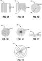
- Figs. 1A-1F provide several examples of geometric patterns 12A-12F that may be created in or on the structural component 10 as appropriate.
- Fig. 1A illustrates an exemplary one-dimensional geometric pattern 12A formed by a series of parallel linear grooves 14A.
- the linear geometric pattern 12A may be appropriate for a cylindrical structural component such as a pipe (not shown) that may be subjected to circumferential or hoop stresses, but minimal stresses in an axial direction.
- the geometric pattern 12A may wrap around the cylindrical structural component with the grooves 14A aligned parallel to a longitudinal axis of the structural components such that strain due to hoop stresses will increase the circumferential groove width WG between the grooves 14A.
- Fig. 1B illustrates an example of a two-dimensional geometric pattern 12B formed by a plurality of square or rectangular grooves 14B.
- the square or rectangular grooves 14B defined increasing areas, and are arranged concentrically to form the geometric pattern 12B.
- the rectangular geometric pattern 12B may have use, for example, in a structural component 10 having a rectangular opening 20 passing there through.
- Fig. 1C illustrates an alternative two-dimensional geometric pattern 12C formed by a plurality of concentric circular grooves 14C defining increasing areas.
- the circular geometric pattern 12C may have application in a structural component 10 where stress on the structural component 10 may be directed radially outward from a point at the center of the geometric pattern 12C.
- 1D illustrates a further example of a geometric pattern 12D having concentric grooves 14D with a more complex geometric shape that may correspond to a shape of an opening or other component extending from the structural component 10. Additional irregular shapes are contemplated based on the needs of a particular implementation in the structural component 10.
- Fig. 1E illustrates a further alternative two-dimensional geometric pattern 12E having a plurality of grooves 14E extending radially outward from a central point 22.
- the geometric pattern 12E may be an alternative to the geometric pattern 12C where circumferential stresses are more prevalent than radial stresses.
- Fig. 1F illustrates a geometric pattern 12F formed by a plurality of parallel curved grooves 14F.
- the curved grooves 14F may follow a contour of a component having a curved shape extending through the structural component 10 such as an aircraft wing.
- the structural component 10 may have areas of interest where it may be desirable to have greater sensitivity to strain and changes in the groove width WG. In such situations, areas of interest may be distinguished by varying the spacing between the grooves 14, the groove width WG and the wavelength across the structural component 10.
- Fig. 1G illustrates a geometric pattern 12G that is a modification of the circular geometric pattern 12C of Fig. 1C wherein a groove spacing distance DG ( Fig. 3 ) between adjacent grooves 14G increases as the geometric pattern 12G extends outward from the center where it may be more critical to closely inspect the radial stresses.
- the area with the smaller groove spacing distance DG and correspondingly higher concentration of grooves 14G may be more sensitive to strain and changes in the groove width WG and produce a more intense response in the wavelength of the reflected light to the projected light in the area of interest than at the area with greater groove spacing distance DG and spaced out remote grooves 14G.
- the geometric pattern 12 may have sets of grooves 14 laid down at angles to each other with different groove widths WG to independently monitor different levels or types of strain occurring in the structural component 10.
- the geometric patterns 12C, 12E may be implemented into a single geometric pattern 12 on the structural component 10.
- the circular geometric pattern 12C may be created with the groove width WG being within the range responsive to infrared light and the geometric pattern 12E created overlying the geometric pattern 12C with the groove width WG being within the range responsive to mid ultraviolet light.
- the radial strains can be interrogated by illuminating the structural component 10 with the infrared light, and the circumferential strain can be interrogated by illuminating the structural component 10 with the mid ultraviolet light.
- Alternative or additional geometric patterns 12 such as those illustrated and described herein can further be created on the structural component 10 with varying groove widths WG and corresponding light wavelengths to inspect for additional strain patterns as necessary in a particular implementation.
- Fig. 2 illustrates an implementation where the structural component is a patch 30 applied over a damaged area of another structural component 32.
- the patch 30 is appropriately shaped to cover the damaged area, and is affixed to the structural component 32 via rivets, welds, adhesive, lamination or other appropriate attachment means.
- the patch 30 includes, for example, the geometric pattern 12C of Fig. 1C .
- the inspection may provide evaluation of the integrity of the application of the patch 30 to the structural component 32. If the patch 30 is properly applied and attached to the structural component 32, stresses in the structural component 32 will be transmitted to the patch 30 and corresponding strain will appear during the inspection. If the patch 30 is not properly applied and conditions such as delamination are present, the stresses may not be transferred and the inspection of the patch 30 will reveal less strain in the patch 30 than expected. Such results may prompt further investigation and reapplication of the patch 30 over the damaged area.
- Fig. 3 illustrates a cross-section of the structural component 32 with the patch 30 applied and of the geometric pattern 12C formed in an outer surface of the patch 30.
- the grooves 14C may have the groove width WG determined based on the wavelength of the light to be used during an inspection, and the groove spacing distance DG between centers of the grooves 14C determined to achieve a desired intensity of response to the inspection light.
- the grooves 14C could also be created in the structural component 32.
- the external surface of the patch 30 may be covered by a layer of material 34, such as a coating of resin that may fill in the grooves 14C.
- An appropriate material may be chosen for the layer of material 34 that would be penetrated by the ultraviolet or infrared light that will illuminate the geometric pattern 12C. Such material will appear invisible to the projected light so that the optical response of the geometric pattern 12C will be detectable through the layer of material 34.
- Fig. 4 illustrates an exemplary arrangement of electrical and control components that may be integrated in the inspection system 50 in accordance with the present disclosure.
- the controller 52 may be capable of processing information received from monitoring and control devices using software stored at the controller 52, and outputting command and control signals to devices of the inspection system 50.
- the controller 52 may include a processor 54 for executing a specified program, which controls and monitors various functions associated with the inspection system 50.
- the processor 54 may be operatively connected to a memory 56 that may have a read only memory (ROM) 58 for storing programs, and a random access memory (RAM) 60 serving as a working memory area for use in executing a program stored in the ROM 58.
- ROM read only memory
- RAM random access memory
- the processor 54 is shown, it is also possible and contemplated to use other electronic components such as a microcontroller, an application specific integrated circuit (ASIC) chip, or any other integrated circuit device.
- ASIC application specific integrated circuit
- the controller 52 may be configured to control other aspects of operation of other systems. Moreover, the controller 52 may refer collectively to multiple control and processing devices across which the functionality of the inspection system 50 and other systems may be distributed. For example, portions of the functionality of the inspection system 50 may be performed at a remote computing device 62 having a controller 64 that is operatively connected to the controller 52 by a communications module 66 of the inspection system 50.
- the remote computing device 62 may be located in the centralized location for an enterprise utilizing the inspection system 50 to perform inspections on mechanical systems.
- the controllers 52, 64 may be operatively connected to exchange information as necessary to control the operation of the inspection system 50.
- Other variations in consolidating and distributing the processing of the controllers 52, 64 as described herein are contemplated as having use in inspection systems 50 in accordance with the present disclosure.
- the inspection system 50 may further include one or more illumination sources 68, 70 capable of projecting light at predetermined wavelengths corresponding to the groove width WG of the grooves 14 and the geometric pattern 12.
- the illumination sources 68, 70 may receive illumination control signals from the processor 54 causing the illumination sources 68, 70 to project light.
- each illumination source 68, 70 may be capable of projecting light at one wavelength.
- each illumination source 68, 70 or a single illumination source may be capable of projecting light at different wavelengths.
- illumination sources 68, 70 are illustrated and described as being operatively connected to the processor 54, those skilled in the art will understand that the illumination sources 68, 70 may be standalone devices having associated input devices such as on/off switches, wavelength selection inputs and the like for manual control of the operation by personnel performing an inspection.
- the inspection system 50 also may include a detector 72 operatively connected to the processor 54.
- the detector 72 may be any device capable of detecting the wavelength of the light reflected from the geometric pattern 12 when illuminated by the illumination sources 68, 70.
- the detector 72 may be an optical detector capable of detecting the wavelength of the reflected light as an optical response such as colors reflected by the geometric pattern 12.
- the detector 72 may be a charge-coupled device (CCD) camera, a video camera, photographic film or other light-sensing apparatus.
- CCD charge-coupled device
- the detector 72 can capture the reflected light and transmit a representation of the detected wavelengths of the reflected lights to the processor 54.
- the processor 54 may store the detected wavelengths in the memory 56. While the embodiments illustrated and described hereinafter utilize changes in color as the detectable variations in wavelength of the reflected light used for strain sensing in the systems and methods of the present disclosure, the use of colors is merely exemplary. Those skilled in the art will understand that detection of the wavelengths or frequencies of the reflected light and determinations of variations in the wavelengths or frequencies may be achieved using alternative mechanisms as desired or necessitated by a particular implementation of the systems and methods described herein, and the use such alternative mechanisms is contemplated by the inventors. Color and color changes are used in the following discussion for simplicity and clarity, and it should be understood that use of any other mechanisms for detection and analysis of the wavelengths of the reflected light has equal application in the systems and methods of the present disclosure.
- the inspection system 50 may have one or more input devices 74 adjustable by an operator to control the inspection process.
- the input device 74 can include switches, buttons, keyboards, mice, touchscreens and the like capable of receiving input commands from an operator.
- Output devices 76 such as monitors, screens, touchscreens, speakers, printers and the like may convey information from the inspection system 50 to the operator.
- the processor 54, the illumination source 68 and the detector 72 are integrated in an inspection workstation 100.
- the inspection workstation 100 may be, for example, a workstation at a maintenance facility for the mechanical system of which the structural component 10 is a part.
- the illumination source 68 may be activated to project light 102 at the appropriate wavelength onto the geometric pattern 12.
- the projected light 102 is diffracted and reflected by the geometric pattern 12 to produce reflected light 104.
- the detector 72 receives and detects the reflected light 104, and transmits the detected reflected light 104 to the processor 54 for analysis and correlation of the detected wavelengths or frequencies of the reflected light 104 into corresponding strain values.
- the processor 54 may be programmed with algorithms known in the art for performing the conversion of the detected wavelengths or frequencies into strain values.
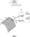
- Fig. 6 illustrates an alternative implementation of the inspection system 50 where the illumination source 68 and the detector 72 are components of a portable inspection device 110 and the processor 54 and the memory 56 are located at a central inspection workstation 112.
- the portable inspection device 110 may be a laptop computer, a tablet, a smart phone, a personal digital assistant or other portable processing device.
- the portable inspection device 110 may further include a communications module 114 capable of wireless communications with the communications module 66 at the central inspection workstation to transmit the detected colors from the detector 72.
- Fig. 7 illustrates an exemplary inspection routine 120 that may be performed on the structural component 10 by the inspection system 50.
- the routine 120 may begin at a block 122 where one or more of the geometric patterns 12, 12A-12G of grooves 14, 14A-14G is or are created on the structural component 10.
- the grooves 14, 14A-14G may be formed in these structural component 10 using any appropriate manufacturing technique.
- the grooves 14, 14A-14G may be etched into a surface of the structural component 10.
- the grooves 14, 14A-14G may be formed in an outer layer and then covered and filled by resin that will be transparent to the light at the wavelength projected onto the geometric pattern 12, 12A-12G.
- the grooves 14, 14A-14G may be formed on an appliqué that is applied to and adhered to the surface of the structural component 10.
- control may pass to a block 124 where the illumination source 68 projects the light 102 with the corresponding wavelength onto the structural component 10 to illuminate the geometric pattern 12, 12A-12G.
- the projected light 102 is diffracted by the grooves 14, 14A-14G and corresponding colors are reflected from the geometric pattern 12, 12A-12G.
- the reflected light 104 may have wavelengths that vary at different locations on the geometric pattern 12, 12A-12G due to changes in the groove width WG caused by strain on the structural component 10.
- control may pass to a block 126 where the reflected light 104 is detected by the detector 72 to detect reflected colors.
- the wavelengths of the detected light 104 may be temporarily stored or permanently stored in the memory 56.
- control may pass to a block 128 where the inspection system 50 may determine whether the last light 102 has been projected onto the geometric pattern 12, 12A-12G.
- some implementations may have a first set of grooves 14, 14A-14G with a first groove width WG that will be illuminated by a first light 102 having a first wavelength, and a second set of grooves 14, 14A-14G with a second groove width WG that will be illuminated by a second light 102 having a second wavelength. In these implementations, it may be necessary to illuminate the geometric pattern 12, 12A-12G with only one light 102 at a time.
- control may pass back to the blocks 124, 126 to illuminate the geometric pattern 12, 12A-12G with the illumination source 68 or 70 and detect the corresponding reflected light 104 for the next light 102 as described above.
- control may pass to a block 130 where the wavelengths of the reflected lights 104 are correlated to strains in the structural component 10.
- the processor 54 may be programmed with algorithms known in the art for correlating wavelengths of reflected lights 104 into strain values. Where colors are the detectable variations in the wavelength, the processor 54 may correlate the reflected colors to the strain values.
- control may pass to a block 132 to determine whether any of the strain values calculated from the wavelengths of the reflected lights exceeds a predetermined minimum strain value above which further inspection or maintenance should be performed. As discussed, certain levels of strain are acceptable in the structural component 10.
- the current strain value may be compared to baseline strain values obtained for the structural component 10 before the mechanical system is placed in service and exposed to environmental conditions. A comparison may be made between the current strain values and the baseline or other previously determined strain values to determine whether the current strain values differ from the previous strain values by more than a minimum amount or percentage.
- control may pass to a block 134 where the structural component 10 is exposed to environmental conditions.
- the exposure may come from normal use in the normal environment of the mechanical system. Where the mechanical system is in a development stage, the environmental condition may be applied in a test environment.
- control may pass back to the block 124 to initiate another instance of inspecting the structural component 10.
- Strain values being greater than the minimum strain value at the block 132 can indicate that further inspection, maintenance or replacement of the structural component 10 may be necessary. If strain values are greater than the minimum strain value at the block 132, control passes to a block 136 where to conduct further inspection of the structural component 10.
- the inspection system 50 and the routine 120 may have broad application in assessing the structural integrity of structural components 10 in mechanical systems.
- the inspection system 50 and the routine 120 may be used in a repair monitoring application to ensure the bond integrity or strength in a repair such as the patch 30 of Fig. 2 to the structural component 32, and the response of the patch 30 to stress and strain over time before the structural component 32 is replaced.
- the geometric pattern 12C of grooves 14C is created in the outer surface of the patch 30, either by etching or otherwise defining the grooves 14C in the surface, or by paint or an appliqué with the grooves 14C that covers the patch 30 and surrounding surface of the structural component 32.
- strains due to bonding can be imaged and analyzed according to the routine 120 to detect residual stresses in the patch 30 and the integrity of the bond of the patch 30 to the structural component 32.
- a baseline image of the patch 30 before the structural component 32 with the patch 30 is exposed to environmental conditions may show any initial strain in the patch 30 and the structural component 32, and periodic imaging after the structural component 32 is exposed to the environmental conditions will monitor the integrity of the bond and the patch 30, and indicate degradation in the repair over time.
- strain values derived through the inspection system 50 and the routine 120 may be input into a finite element analysis (FEA) model of the patch 30 on the structural component 32 and analyzed to provide performance assessments of the patch 30, prospective inspection schedules, and approaches to NDI and predictive maintenance and repair plans.
- FFA finite element analysis
- the inspection system 50 and the routine 120 may have application in structural testing environments.
- Manufacturers typically conduct subscale, midscale and full-scale structural testing of components and repairs to ensure proper performance in the field. Such testing can involve static and dynamic loading conditions.
- strain gauges are applied to structural components as point sensors for monitoring stress and strain during the tests, but their effectiveness in detecting locations in which damage to the structural component initiates and propagates is dependent on where the strain gauges are placed on the structural component.
- Digital Image Correlation may be used to provide stream mapping during structural testing, but the process can be expensive, requires expertise in operation, and necessitate spraying a speckled pattern on the surface. Consequently, DIC may be used judiciously in structural testing.
- the inspection system 50 and the routine 120 may be used as an alternative or a supplement to the currently-used testing techniques, and can be used to monitor and measure real-time strain patterns throughout the test loading conditions.
- the detected strain patterns can be used to correlate analysis models, and to point to or indicate initial failure locations in the structural component being tested.
- direct feed of the strain information in the FEA tools can provide real-time or load-level damage growth information.
- the damage initiation and growth information can be used to improve the structural models of the structural components and modify the structural designs.
- the inspection system 50 and the routine 120 may be used to improve the fabrication process of composite components that are becoming more prevalent in mechanical systems, and in particular in aerospace systems.
- the internal strains may be tracked through the use of strain indicator plies in a composite component that are configured with geometric patterns 12, 12A-12G.
- the geometric pattern 12, 12A-12G is applied to the resin in selected plies during fabrication as an additional resin layer sprayed onto the ply that is subsequently configured with the geometric pattern 12, 12A-12G, or as an appliqué that forms a peelable ply that may be removed after the composite component is cured.
- the strain indicator plies will show residual stresses and strains that exist in the composite component due to the curing process.
- the information from the strain indicator plies can be used to modify the manufacturing process of the composite component to reduce warpage, predict performance and verify that the production process is still within specification.
- the inspection system 50 and the routine 120 may also have application in monitoring the structural health of structural components disposed in limited access areas of their mechanical systems.
- Limited access structures on aircraft and other mechanical systems can be critical to structural integrity and can experience high loading. Structural health testing of such limited access structures may necessitate costly disassembly and reassembly processes.
- Strain witness surfaces in the form of the geometric patterns 12, 12A-12G of grooves 14, 14A-14G created for the limited access structures can be installed during manufacturing, or after previous damage indicates that the structure should be more closely monitored.
- Optical or video borescopes or small cameras and extending mechanisms can function as the illumination source 68 and detector 72 in the inspection system 50 and be used to image the geometric patterns 12, 12A-12G on the limited access structures and allow analysis of the image data to detect degradation of the components and monitor slow damage growth until a repair is needed, for example.
- the strain images can be combined with other NDI methods, such as infrared thermography, my great camera imaging or terahertz imaging, to provide an improved assessment and disposition of the limited access components.
Landscapes
- Physics & Mathematics (AREA)
- General Physics & Mathematics (AREA)
- Engineering & Computer Science (AREA)
- Aviation & Aerospace Engineering (AREA)
- Pathology (AREA)
- Health & Medical Sciences (AREA)
- Life Sciences & Earth Sciences (AREA)
- Chemical & Material Sciences (AREA)
- Analytical Chemistry (AREA)
- Biochemistry (AREA)
- General Health & Medical Sciences (AREA)
- Immunology (AREA)
- Spectroscopy & Molecular Physics (AREA)
- Electromagnetism (AREA)
- Length Measuring Devices By Optical Means (AREA)
- Investigating Materials By The Use Of Optical Means Adapted For Particular Applications (AREA)
- Investigating Or Analysing Materials By Optical Means (AREA)
Applications Claiming Priority (1)
| Application Number | Priority Date | Filing Date | Title |
|---|---|---|---|
| US15/948,582 US10801833B2 (en) | 2018-04-09 | 2018-04-09 | Strain sensitive surfaces for aircraft structural analysis and health monitoring |
Publications (2)
| Publication Number | Publication Date |
|---|---|
| EP3553464A1 true EP3553464A1 (de) | 2019-10-16 |
| EP3553464B1 EP3553464B1 (de) | 2023-08-09 |
Family
ID=65493851
Family Applications (1)
| Application Number | Title | Priority Date | Filing Date |
|---|---|---|---|
| EP19157628.9A Active EP3553464B1 (de) | 2018-04-09 | 2019-02-18 | Dehnungsempfindliche oberflächen für die strukturanalyse und zustandsüberwachung von flugzeugen |
Country Status (6)
| Country | Link |
|---|---|
| US (1) | US10801833B2 (de) |
| EP (1) | EP3553464B1 (de) |
| JP (2) | JP7668084B2 (de) |
| KR (1) | KR102735654B1 (de) |
| CN (1) | CN110360943B (de) |
| SG (1) | SG10201903121TA (de) |
Cited By (1)
| Publication number | Priority date | Publication date | Assignee | Title |
|---|---|---|---|---|
| WO2022269172A1 (fr) * | 2021-06-23 | 2022-12-29 | Centre National De La Recherche Scientifique | Procede de caracterisation d'une piece mecanique |
Families Citing this family (5)
| Publication number | Priority date | Publication date | Assignee | Title |
|---|---|---|---|---|
| US12007220B2 (en) * | 2017-12-29 | 2024-06-11 | II John Tyson | Optical structural health monitoring |
| US11486697B1 (en) * | 2017-12-29 | 2022-11-01 | II John Tyson | Optical structural health monitoring |
| US11243071B2 (en) | 2020-02-03 | 2022-02-08 | The Boeing Company | Sub-surface patterning for diffraction-based strain measurement and damage detection in structures |
| DE102020131668B4 (de) * | 2020-11-30 | 2023-09-07 | Audi Aktiengesellschaft | Überwachungsvorrichtung zum Erfassen einer vorbestimmten lokalen Verformung einer Oberfläche eines Bauteils und Vorrichtung mit einer solchen Überwachungsvorrichtung |
| US12098975B2 (en) | 2021-02-23 | 2024-09-24 | The Boeing Company | Methods, systems, and apparatuses for non-destructively inspecting, detecting, and measuring structural component internal deformation and strain by correlating density variations of induced material density patterns |
Citations (3)
| Publication number | Priority date | Publication date | Assignee | Title |
|---|---|---|---|---|
| US6584857B1 (en) * | 2000-11-20 | 2003-07-01 | Eastman Kodak Company | Optical strain gauge |
| US20170059890A1 (en) * | 2015-08-26 | 2017-03-02 | Apple Inc. | Flexible photonic crystals with color-changing strain response |
| US20170276614A1 (en) * | 2016-03-28 | 2017-09-28 | Saudi Arabian Oil Company | Systems and methods for constructing and testing composite photonic structures |
Family Cites Families (29)
| Publication number | Priority date | Publication date | Assignee | Title |
|---|---|---|---|---|
| US4322162A (en) | 1979-07-23 | 1982-03-30 | National Research Development Corporation | Method and apparatus for sensing in-plane deformation of a surface |
| US4874941A (en) | 1988-05-11 | 1989-10-17 | Simmonds Precision Products, Inc. | Optical displacement sensor with a multi-period grating |
| US4939368A (en) * | 1989-04-13 | 1990-07-03 | Massachusetts Institute Of Technology | Polychromatic optical strain gauge |
| US5399854A (en) * | 1994-03-08 | 1995-03-21 | United Technologies Corporation | Embedded optical sensor capable of strain and temperature measurement using a single diffraction grating |
| US5430817A (en) * | 1994-03-31 | 1995-07-04 | At&T Corp. | Optical systems and devices using long period spectral shaping devices |
| JPH08285527A (ja) * | 1995-04-12 | 1996-11-01 | Shinichi Katsura | 変位検出装置及び変位検出方法 |
| US6321601B1 (en) * | 1996-08-06 | 2001-11-27 | Brown University Research Foundation | Optical method for the characterization of laterally-patterned samples in integrated circuits |
| JP3739130B2 (ja) * | 1996-05-28 | 2006-01-25 | 松下電器産業株式会社 | 移動物体の変位検出方法およびその装置 |
| US5760391A (en) * | 1996-07-17 | 1998-06-02 | Mechanical Technology, Inc. | Passive optical wavelength analyzer with a passive nonuniform optical grating |
| EP1179212A2 (de) * | 1999-12-24 | 2002-02-13 | Koninklijke Philips Electronics N.V. | Optischer abtastkopf |
| CA2322552A1 (en) * | 2000-09-26 | 2002-03-26 | Jds Uniphase Inc. | Scheme for measuring dispersion of chirped fbg and generating tunable narrow-band bandpass and notch filters using chirped fbg |
| GB0030289D0 (en) * | 2000-12-12 | 2001-01-24 | Optoplan As | Fibre optic sensor systems |
| AU2004219914B2 (en) * | 2003-03-05 | 2007-02-22 | Shell Internationale Research Maatschappij B.V. | Coiled optical fiber assembly for measuring pressure and/or other physical data |
| US7276406B2 (en) * | 2004-10-29 | 2007-10-02 | Freescale Semiconductor, Inc. | Transistor structure with dual trench for optimized stress effect and method therefor |
| BRPI0822792B1 (pt) * | 2008-09-23 | 2019-04-16 | Voith Patent Gmbh | Rolo industrial com sistema sensor de cobertura do rolo ótico |
| US8581736B2 (en) | 2010-06-24 | 2013-11-12 | The Boeing Company | Assessing structural repair integrity |
| US8853805B2 (en) * | 2011-06-27 | 2014-10-07 | Texas Instruments Incorporated | Strain measurement test module |
| KR20140061544A (ko) * | 2011-09-16 | 2014-05-21 | 에이에스엠엘 네델란즈 비.브이. | 리소그래피 패터닝 디바이스를 모니터링하는 장치 |
| KR20140044237A (ko) * | 2012-10-04 | 2014-04-14 | 삼성전자주식회사 | 플렉서블 장치 및 그의 제어 방법 |
| US10156488B2 (en) * | 2013-08-29 | 2018-12-18 | Corning Incorporated | Prism-coupling systems and methods for characterizing curved parts |
| US10390705B2 (en) * | 2013-10-30 | 2019-08-27 | National Chiao Tung University | Portable noninvasive inspection device |
| US9970833B2 (en) | 2014-04-23 | 2018-05-15 | The Boeing Company | Witness material and method for monitoring the environmental history of an object |
| JP6404070B2 (ja) * | 2014-10-01 | 2018-10-10 | 国立研究開発法人産業技術総合研究所 | マルチスケール変形計測用格子パターンとその製作方法 |
| US9677592B2 (en) * | 2014-11-03 | 2017-06-13 | The Boeing Company | Witness enabled fasteners and related systems and methods |
| US10502719B2 (en) | 2015-08-21 | 2019-12-10 | The Boeing Company | Analysis of a structure modeled with inconsistencies mapped thereon |
| CN106840012A (zh) | 2015-12-07 | 2017-06-13 | 上海新力动力设备研究所 | 一种基于光栅传感技术的固发装药ii界面应变测量方法 |
| JP2017129510A (ja) * | 2016-01-22 | 2017-07-27 | コニカミノルタ株式会社 | 測定装置及び測定方法 |
| US10539473B2 (en) | 2016-08-08 | 2020-01-21 | The Boeing Company | Systems for monitoring the environmental history of a component |
| JP2019029322A (ja) * | 2017-08-03 | 2019-02-21 | サムテック・イノベーションズ株式会社 | 医療用無影灯 |
-
2018
- 2018-04-09 US US15/948,582 patent/US10801833B2/en active Active
-
2019
- 2019-02-18 EP EP19157628.9A patent/EP3553464B1/de active Active
- 2019-02-21 JP JP2019029322A patent/JP7668084B2/ja active Active
- 2019-03-13 KR KR1020190028593A patent/KR102735654B1/ko active Active
- 2019-04-08 SG SG10201903121T patent/SG10201903121TA/en unknown
- 2019-04-09 CN CN201910280155.8A patent/CN110360943B/zh active Active
-
2023
- 2023-09-07 JP JP2023145303A patent/JP2023165747A/ja active Pending
Patent Citations (3)
| Publication number | Priority date | Publication date | Assignee | Title |
|---|---|---|---|---|
| US6584857B1 (en) * | 2000-11-20 | 2003-07-01 | Eastman Kodak Company | Optical strain gauge |
| US20170059890A1 (en) * | 2015-08-26 | 2017-03-02 | Apple Inc. | Flexible photonic crystals with color-changing strain response |
| US20170276614A1 (en) * | 2016-03-28 | 2017-09-28 | Saudi Arabian Oil Company | Systems and methods for constructing and testing composite photonic structures |
Cited By (2)
| Publication number | Priority date | Publication date | Assignee | Title |
|---|---|---|---|---|
| WO2022269172A1 (fr) * | 2021-06-23 | 2022-12-29 | Centre National De La Recherche Scientifique | Procede de caracterisation d'une piece mecanique |
| FR3124590A1 (fr) * | 2021-06-23 | 2022-12-30 | Centre National De La Recherche Scientifique | Procédé de caractérisation d’une pièce mécanique |
Also Published As
| Publication number | Publication date |
|---|---|
| CN110360943B (zh) | 2022-10-11 |
| SG10201903121TA (en) | 2019-11-28 |
| EP3553464B1 (de) | 2023-08-09 |
| JP7668084B2 (ja) | 2025-04-24 |
| JP2019184579A (ja) | 2019-10-24 |
| KR20190118110A (ko) | 2019-10-17 |
| CN110360943A (zh) | 2019-10-22 |
| JP2023165747A (ja) | 2023-11-17 |
| KR102735654B1 (ko) | 2024-11-27 |
| US10801833B2 (en) | 2020-10-13 |
| US20190310076A1 (en) | 2019-10-10 |
Similar Documents
| Publication | Publication Date | Title |
|---|---|---|
| EP3553464B1 (de) | Dehnungsempfindliche oberflächen für die strukturanalyse und zustandsüberwachung von flugzeugen | |
| EP3708946B1 (de) | Unteroberflächenstrukturierung für beugungsbasierte dehnungsmessung und beschädigungsdetektion in strukturen | |
| EP2894451B1 (de) | Detektion und Erfassung von Schäden an Verbundstrukturen | |
| JP6557299B2 (ja) | 汚染特定システム | |
| JP6328130B2 (ja) | 炭素繊維材料の繊維方向の測定および炭素繊維複合構造での物体の製造 | |
| US20080312847A1 (en) | Method and apparatus for nondestructive corrosion detection using quantum dots | |
| JP2009537835A (ja) | 振動解析による構造体の非破壊検査装置 | |
| US9952081B2 (en) | System and method for measuring liquid levels having a fiber with a strain layer around a Bragg grating | |
| US10215682B2 (en) | Methods, device and apparatus for evaluating electrical current threat effects at joints | |
| KR102959526B1 (ko) | 회절 기반 스트레인 측정 및 구조물들의 손상 검출을 위한 표면 하부 패터닝 | |
| EP3859270B1 (de) | Unteroberflächenstrukturierung für beugungsbasierte dehnungsmessung und beschädigungsdetektion in strukturen | |
| US20220268663A1 (en) | Methods, Systems, and Apparatuses for Non-Destructively Inspecting, Detecting, and Measuring Structural Component Internal Deformation and Strain by Correlating Density Variations of Induced Material Density Patterns | |
| KR20200019695A (ko) | 저장 탱크 모니터링 및 캘리브레이션을 위한 스마트 코팅 디바이스 | |
| BR102020004833B1 (pt) | Sistema de inspeção para avaliar o esforço em um componente estrutural e método para acessar o esforço em um componente estrutural | |
| Začal et al. | ANALYSIS OF SURFACE DEFECTS IN COMPOSITES USING DIGITAL IMAGE CORRELATION AND ACOUSTIC EMISSION. |
Legal Events
| Date | Code | Title | Description |
|---|---|---|---|
| PUAI | Public reference made under article 153(3) epc to a published international application that has entered the european phase |
Free format text: ORIGINAL CODE: 0009012 |
|
| STAA | Information on the status of an ep patent application or granted ep patent |
Free format text: STATUS: REQUEST FOR EXAMINATION WAS MADE |
|
| 17P | Request for examination filed |
Effective date: 20190218 |
|
| AK | Designated contracting states |
Kind code of ref document: A1 Designated state(s): AL AT BE BG CH CY CZ DE DK EE ES FI FR GB GR HR HU IE IS IT LI LT LU LV MC MK MT NL NO PL PT RO RS SE SI SK SM TR |
|
| AX | Request for extension of the european patent |
Extension state: BA ME |
|
| RBV | Designated contracting states (corrected) |
Designated state(s): AL AT BE BG CH CY CZ DE DK EE ES FI FR GB GR HR HU IE IS IT LI LT LU LV MC MK MT NL NO PL PT RO RS SE SI SK SM TR |
|
| STAA | Information on the status of an ep patent application or granted ep patent |
Free format text: STATUS: EXAMINATION IS IN PROGRESS |
|
| 17Q | First examination report despatched |
Effective date: 20210723 |
|
| RAP3 | Party data changed (applicant data changed or rights of an application transferred) |
Owner name: THE BOEING COMPANY |
|
| GRAP | Despatch of communication of intention to grant a patent |
Free format text: ORIGINAL CODE: EPIDOSNIGR1 |
|
| STAA | Information on the status of an ep patent application or granted ep patent |
Free format text: STATUS: GRANT OF PATENT IS INTENDED |
|
| INTG | Intention to grant announced |
Effective date: 20230330 |
|
| GRAS | Grant fee paid |
Free format text: ORIGINAL CODE: EPIDOSNIGR3 |
|
| GRAA | (expected) grant |
Free format text: ORIGINAL CODE: 0009210 |
|
| STAA | Information on the status of an ep patent application or granted ep patent |
Free format text: STATUS: THE PATENT HAS BEEN GRANTED |
|
| P01 | Opt-out of the competence of the unified patent court (upc) registered |
Effective date: 20230628 |
|
| AK | Designated contracting states |
Kind code of ref document: B1 Designated state(s): AL AT BE BG CH CY CZ DE DK EE ES FI FR GB GR HR HU IE IS IT LI LT LU LV MC MK MT NL NO PL PT RO RS SE SI SK SM TR |
|
| REG | Reference to a national code |
Ref country code: GB Ref legal event code: FG4D |
|
| REG | Reference to a national code |
Ref country code: CH Ref legal event code: EP |
|
| REG | Reference to a national code |
Ref country code: DE Ref legal event code: R096 Ref document number: 602019034373 Country of ref document: DE |
|
| REG | Reference to a national code |
Ref country code: IE Ref legal event code: FG4D |
|
| REG | Reference to a national code |
Ref country code: LT Ref legal event code: MG9D |
|
| REG | Reference to a national code |
Ref country code: NL Ref legal event code: MP Effective date: 20230809 |
|
| REG | Reference to a national code |
Ref country code: AT Ref legal event code: MK05 Ref document number: 1597990 Country of ref document: AT Kind code of ref document: T Effective date: 20230809 |
|
| PG25 | Lapsed in a contracting state [announced via postgrant information from national office to epo] |
Ref country code: GR Free format text: LAPSE BECAUSE OF FAILURE TO SUBMIT A TRANSLATION OF THE DESCRIPTION OR TO PAY THE FEE WITHIN THE PRESCRIBED TIME-LIMIT Effective date: 20231110 |
|
| PG25 | Lapsed in a contracting state [announced via postgrant information from national office to epo] |
Ref country code: IS Free format text: LAPSE BECAUSE OF FAILURE TO SUBMIT A TRANSLATION OF THE DESCRIPTION OR TO PAY THE FEE WITHIN THE PRESCRIBED TIME-LIMIT Effective date: 20231209 |
|
| PG25 | Lapsed in a contracting state [announced via postgrant information from national office to epo] |
Ref country code: SE Free format text: LAPSE BECAUSE OF FAILURE TO SUBMIT A TRANSLATION OF THE DESCRIPTION OR TO PAY THE FEE WITHIN THE PRESCRIBED TIME-LIMIT Effective date: 20230809 Ref country code: RS Free format text: LAPSE BECAUSE OF FAILURE TO SUBMIT A TRANSLATION OF THE DESCRIPTION OR TO PAY THE FEE WITHIN THE PRESCRIBED TIME-LIMIT Effective date: 20230809 Ref country code: PT Free format text: LAPSE BECAUSE OF FAILURE TO SUBMIT A TRANSLATION OF THE DESCRIPTION OR TO PAY THE FEE WITHIN THE PRESCRIBED TIME-LIMIT Effective date: 20231211 Ref country code: NO Free format text: LAPSE BECAUSE OF FAILURE TO SUBMIT A TRANSLATION OF THE DESCRIPTION OR TO PAY THE FEE WITHIN THE PRESCRIBED TIME-LIMIT Effective date: 20231109 Ref country code: NL Free format text: LAPSE BECAUSE OF FAILURE TO SUBMIT A TRANSLATION OF THE DESCRIPTION OR TO PAY THE FEE WITHIN THE PRESCRIBED TIME-LIMIT Effective date: 20230809 Ref country code: LV Free format text: LAPSE BECAUSE OF FAILURE TO SUBMIT A TRANSLATION OF THE DESCRIPTION OR TO PAY THE FEE WITHIN THE PRESCRIBED TIME-LIMIT Effective date: 20230809 Ref country code: LT Free format text: LAPSE BECAUSE OF FAILURE TO SUBMIT A TRANSLATION OF THE DESCRIPTION OR TO PAY THE FEE WITHIN THE PRESCRIBED TIME-LIMIT Effective date: 20230809 Ref country code: IS Free format text: LAPSE BECAUSE OF FAILURE TO SUBMIT A TRANSLATION OF THE DESCRIPTION OR TO PAY THE FEE WITHIN THE PRESCRIBED TIME-LIMIT Effective date: 20231209 Ref country code: HR Free format text: LAPSE BECAUSE OF FAILURE TO SUBMIT A TRANSLATION OF THE DESCRIPTION OR TO PAY THE FEE WITHIN THE PRESCRIBED TIME-LIMIT Effective date: 20230809 Ref country code: GR Free format text: LAPSE BECAUSE OF FAILURE TO SUBMIT A TRANSLATION OF THE DESCRIPTION OR TO PAY THE FEE WITHIN THE PRESCRIBED TIME-LIMIT Effective date: 20231110 Ref country code: FI Free format text: LAPSE BECAUSE OF FAILURE TO SUBMIT A TRANSLATION OF THE DESCRIPTION OR TO PAY THE FEE WITHIN THE PRESCRIBED TIME-LIMIT Effective date: 20230809 Ref country code: AT Free format text: LAPSE BECAUSE OF FAILURE TO SUBMIT A TRANSLATION OF THE DESCRIPTION OR TO PAY THE FEE WITHIN THE PRESCRIBED TIME-LIMIT Effective date: 20230809 |
|
| PG25 | Lapsed in a contracting state [announced via postgrant information from national office to epo] |
Ref country code: PL Free format text: LAPSE BECAUSE OF FAILURE TO SUBMIT A TRANSLATION OF THE DESCRIPTION OR TO PAY THE FEE WITHIN THE PRESCRIBED TIME-LIMIT Effective date: 20230809 |
|
| PG25 | Lapsed in a contracting state [announced via postgrant information from national office to epo] |
Ref country code: ES Free format text: LAPSE BECAUSE OF FAILURE TO SUBMIT A TRANSLATION OF THE DESCRIPTION OR TO PAY THE FEE WITHIN THE PRESCRIBED TIME-LIMIT Effective date: 20230809 |
|
| PG25 | Lapsed in a contracting state [announced via postgrant information from national office to epo] |
Ref country code: SM Free format text: LAPSE BECAUSE OF FAILURE TO SUBMIT A TRANSLATION OF THE DESCRIPTION OR TO PAY THE FEE WITHIN THE PRESCRIBED TIME-LIMIT Effective date: 20230809 Ref country code: RO Free format text: LAPSE BECAUSE OF FAILURE TO SUBMIT A TRANSLATION OF THE DESCRIPTION OR TO PAY THE FEE WITHIN THE PRESCRIBED TIME-LIMIT Effective date: 20230809 Ref country code: ES Free format text: LAPSE BECAUSE OF FAILURE TO SUBMIT A TRANSLATION OF THE DESCRIPTION OR TO PAY THE FEE WITHIN THE PRESCRIBED TIME-LIMIT Effective date: 20230809 Ref country code: EE Free format text: LAPSE BECAUSE OF FAILURE TO SUBMIT A TRANSLATION OF THE DESCRIPTION OR TO PAY THE FEE WITHIN THE PRESCRIBED TIME-LIMIT Effective date: 20230809 Ref country code: DK Free format text: LAPSE BECAUSE OF FAILURE TO SUBMIT A TRANSLATION OF THE DESCRIPTION OR TO PAY THE FEE WITHIN THE PRESCRIBED TIME-LIMIT Effective date: 20230809 Ref country code: CZ Free format text: LAPSE BECAUSE OF FAILURE TO SUBMIT A TRANSLATION OF THE DESCRIPTION OR TO PAY THE FEE WITHIN THE PRESCRIBED TIME-LIMIT Effective date: 20230809 Ref country code: SK Free format text: LAPSE BECAUSE OF FAILURE TO SUBMIT A TRANSLATION OF THE DESCRIPTION OR TO PAY THE FEE WITHIN THE PRESCRIBED TIME-LIMIT Effective date: 20230809 |
|
| REG | Reference to a national code |
Ref country code: DE Ref legal event code: R097 Ref document number: 602019034373 Country of ref document: DE |
|
| PG25 | Lapsed in a contracting state [announced via postgrant information from national office to epo] |
Ref country code: IT Free format text: LAPSE BECAUSE OF FAILURE TO SUBMIT A TRANSLATION OF THE DESCRIPTION OR TO PAY THE FEE WITHIN THE PRESCRIBED TIME-LIMIT Effective date: 20230809 |
|
| PLBE | No opposition filed within time limit |
Free format text: ORIGINAL CODE: 0009261 |
|
| STAA | Information on the status of an ep patent application or granted ep patent |
Free format text: STATUS: NO OPPOSITION FILED WITHIN TIME LIMIT |
|
| 26N | No opposition filed |
Effective date: 20240513 |
|
| PG25 | Lapsed in a contracting state [announced via postgrant information from national office to epo] |
Ref country code: SI Free format text: LAPSE BECAUSE OF FAILURE TO SUBMIT A TRANSLATION OF THE DESCRIPTION OR TO PAY THE FEE WITHIN THE PRESCRIBED TIME-LIMIT Effective date: 20230809 |
|
| PG25 | Lapsed in a contracting state [announced via postgrant information from national office to epo] |
Ref country code: MC Free format text: LAPSE BECAUSE OF FAILURE TO SUBMIT A TRANSLATION OF THE DESCRIPTION OR TO PAY THE FEE WITHIN THE PRESCRIBED TIME-LIMIT Effective date: 20230809 |
|
| REG | Reference to a national code |
Ref country code: CH Ref legal event code: PL |
|
| PG25 | Lapsed in a contracting state [announced via postgrant information from national office to epo] |
Ref country code: LU Free format text: LAPSE BECAUSE OF NON-PAYMENT OF DUE FEES Effective date: 20240218 |
|
| PG25 | Lapsed in a contracting state [announced via postgrant information from national office to epo] |
Ref country code: CH Free format text: LAPSE BECAUSE OF NON-PAYMENT OF DUE FEES Effective date: 20240229 |
|
| PG25 | Lapsed in a contracting state [announced via postgrant information from national office to epo] |
Ref country code: LU Free format text: LAPSE BECAUSE OF NON-PAYMENT OF DUE FEES Effective date: 20240218 Ref country code: CH Free format text: LAPSE BECAUSE OF NON-PAYMENT OF DUE FEES Effective date: 20240229 |
|
| PG25 | Lapsed in a contracting state [announced via postgrant information from national office to epo] |
Ref country code: BG Free format text: LAPSE BECAUSE OF FAILURE TO SUBMIT A TRANSLATION OF THE DESCRIPTION OR TO PAY THE FEE WITHIN THE PRESCRIBED TIME-LIMIT Effective date: 20230809 |
|
| PG25 | Lapsed in a contracting state [announced via postgrant information from national office to epo] |
Ref country code: BG Free format text: LAPSE BECAUSE OF FAILURE TO SUBMIT A TRANSLATION OF THE DESCRIPTION OR TO PAY THE FEE WITHIN THE PRESCRIBED TIME-LIMIT Effective date: 20230809 |
|
| REG | Reference to a national code |
Ref country code: BE Ref legal event code: MM Effective date: 20240229 |
|
| PG25 | Lapsed in a contracting state [announced via postgrant information from national office to epo] |
Ref country code: BE Free format text: LAPSE BECAUSE OF NON-PAYMENT OF DUE FEES Effective date: 20240229 |
|
| PG25 | Lapsed in a contracting state [announced via postgrant information from national office to epo] |
Ref country code: IE Free format text: LAPSE BECAUSE OF NON-PAYMENT OF DUE FEES Effective date: 20240218 |
|
| PG25 | Lapsed in a contracting state [announced via postgrant information from national office to epo] |
Ref country code: IE Free format text: LAPSE BECAUSE OF NON-PAYMENT OF DUE FEES Effective date: 20240218 Ref country code: BE Free format text: LAPSE BECAUSE OF NON-PAYMENT OF DUE FEES Effective date: 20240229 |
|
| PG25 | Lapsed in a contracting state [announced via postgrant information from national office to epo] |
Ref country code: CY Free format text: LAPSE BECAUSE OF FAILURE TO SUBMIT A TRANSLATION OF THE DESCRIPTION OR TO PAY THE FEE WITHIN THE PRESCRIBED TIME-LIMIT; INVALID AB INITIO Effective date: 20190218 |
|
| PG25 | Lapsed in a contracting state [announced via postgrant information from national office to epo] |
Ref country code: HU Free format text: LAPSE BECAUSE OF FAILURE TO SUBMIT A TRANSLATION OF THE DESCRIPTION OR TO PAY THE FEE WITHIN THE PRESCRIBED TIME-LIMIT; INVALID AB INITIO Effective date: 20190218 |
|
| PG25 | Lapsed in a contracting state [announced via postgrant information from national office to epo] |
Ref country code: TR Free format text: LAPSE BECAUSE OF FAILURE TO SUBMIT A TRANSLATION OF THE DESCRIPTION OR TO PAY THE FEE WITHIN THE PRESCRIBED TIME-LIMIT Effective date: 20230809 |
|
| PGFP | Annual fee paid to national office [announced via postgrant information from national office to epo] |
Ref country code: GB Payment date: 20260227 Year of fee payment: 8 |
|
| PGFP | Annual fee paid to national office [announced via postgrant information from national office to epo] |
Ref country code: DE Payment date: 20260227 Year of fee payment: 8 |
|
| PGFP | Annual fee paid to national office [announced via postgrant information from national office to epo] |
Ref country code: FR Payment date: 20260225 Year of fee payment: 8 |