EP3553378A1 - Procédé et brûleur pour la combustion d'hydrogène sulfuré - Google Patents
Procédé et brûleur pour la combustion d'hydrogène sulfuré Download PDFInfo
- Publication number
- EP3553378A1 EP3553378A1 EP18020148.5A EP18020148A EP3553378A1 EP 3553378 A1 EP3553378 A1 EP 3553378A1 EP 18020148 A EP18020148 A EP 18020148A EP 3553378 A1 EP3553378 A1 EP 3553378A1
- Authority
- EP
- European Patent Office
- Prior art keywords
- burner
- tubes
- port
- supplied
- tube
- Prior art date
- Legal status (The legal status is an assumption and is not a legal conclusion. Google has not performed a legal analysis and makes no representation as to the accuracy of the status listed.)
- Withdrawn
Links
Images


Classifications
-
- C—CHEMISTRY; METALLURGY
- C01—INORGANIC CHEMISTRY
- C01B—NON-METALLIC ELEMENTS; COMPOUNDS THEREOF; METALLOIDS OR COMPOUNDS THEREOF NOT COVERED BY SUBCLASS C01C
- C01B17/00—Sulfur; Compounds thereof
- C01B17/02—Preparation of sulfur; Purification
- C01B17/04—Preparation of sulfur; Purification from gaseous sulfur compounds including gaseous sulfides
- C01B17/0404—Preparation of sulfur; Purification from gaseous sulfur compounds including gaseous sulfides by processes comprising a dry catalytic conversion of hydrogen sulfide-containing gases, e.g. the Claus process
- C01B17/0413—Preparation of sulfur; Purification from gaseous sulfur compounds including gaseous sulfides by processes comprising a dry catalytic conversion of hydrogen sulfide-containing gases, e.g. the Claus process characterised by the combustion step
- C01B17/0417—Combustion reactors
-
- F—MECHANICAL ENGINEERING; LIGHTING; HEATING; WEAPONS; BLASTING
- F23—COMBUSTION APPARATUS; COMBUSTION PROCESSES
- F23D—BURNERS
- F23D14/00—Burners for combustion of a gas, e.g. of a gas stored under pressure as a liquid
- F23D14/20—Non-premix gas burners, i.e. in which gaseous fuel is mixed with combustion air on arrival at the combustion zone
- F23D14/22—Non-premix gas burners, i.e. in which gaseous fuel is mixed with combustion air on arrival at the combustion zone with separate air and gas feed ducts, e.g. with ducts running parallel or crossing each other
Definitions
- the present invention relates to a method and a burner for combusting hydrogen sulphide (H 2 S) with oxygen, the outlet of the burner being connected to a furnace which is heated by a burner flame including the step of preheating the furnace. More generally, the present invention relates to the partial oxidation (partial combustion) of hydrogen sulphide for forming sulphur.
- Hydrogen sulphide containing gas streams are particularly formed in oil refineries and natural gas processing units. Such streams cannot be vented directly to the atmosphere because hydrogen sulphide is poisonous.
- a conventional method of treating a hydrogen sulphide containing gas stream is by the well known Claus process. In this process a part of the hydrogen sulphide content of the gas stream is combined with an oxidant gas such as air and is subjected to combustion in a furnace so as to form sulphur dioxide. The sulphur dioxide then reacts in the furnace with residual hydrogen sulphide so as to form sulphur vapor. Thus, the hydrogen sulphide is effectively partially oxidized.
- the reaction between hydrogen sulphide and sulphur dioxide does not go to completion.
- the effluent gas stream from the furnace is cooled and sulphur is extracted, typically by condensation, from the cooled effluent gas stream.
- the resulting gas stream still containing residual hydrogen sulphide and sulphur dioxide, passes through a train of stages in which catalysed reaction between the residual hydrogen sulphide and the sulphur dioxide takes place.
- the sulphur vapor produced is condensed downstream of each stage.
- Axially - or longitudinally - fired burners mounted on the back wall of a furnace may be used in Claus furnaces. Such burners are known from EP 0315 225 A1 and from GB 2467930 A .
- Air or more efficiently, commercially pure oxygen or oxygen-enriched air can be used as an oxidant gas to support the combustion of hydrogen sulphide in the initial part of the Claus process.
- commercially pure oxygen or oxygen-enriched air having a mole fraction of oxygen above 0.65 is used as an oxidant gas, there may be a relatively high risk of damage to the refractory lining of the furnace due to the resulting high flame temperature. The degree of this risk will also depend on the composition of the Claus feed gas.
- preheating of the furnace is necessary.
- the preheating process is done by a pilot burner which is installed separately from the main burner and typically close to the main burner in the furnace. With the pilot burner a dry-out and warm-up process typically having a thermal energy rate of 50 K/h is performed until the inner of the furnace reaches a temperature of more than about 1000 degree Celsius. Before taking the main burner into operation, the pilot burner has to be removed or pulled out of the furnace after completion of the preheating process as due to the high temperatures of the main burner flame, there is a risk of damaging the pilot burner.
- oxygen generally an oxidant gas
- the general idea underlying the present invention is to integrate or incorporate the pilot burner into the main burner.
- This general idea leads to a burner according to a first aspect of the present invention and to another burner according to a second aspect of the present invention.
- a method of combusting hydrogen sulphide with oxygen according to the first aspect of the invention and another method of combusting hydrogen sulphide with oxygen according to the second aspect of the present invention are given.
- the methods and burners according to the first and second aspects of the present invention are the subject-matters of the independent claims. Preferred embodiments are given in the dependent claims and in the description which follows.
- the outlet of the burner being connected to a furnace which is heated by a burner flame
- the method including the step of preheating the furnace, during the preheating step, a first fuel gas is supplied through a first port of the burner, the first port being connected to a plurality of first tubes extending to the burner outlet, a first oxidant gas is supplied to a second port of the burner, the second port being connected to a plurality of second tubes spaced from and coaxial with the first tubes, and a second oxidant gas or second fuel gas is supplied through a third port of the burner, the third port being connected to a plurality of third tubes spaced from and coaxial with the second tubes.
- the preheating process serves the purpose of starting-up the furnace and to slowly ramp up the temperature inside the furnace vessel to avoid thermal stresses on the refractory lining of the furnace.
- the normal operation of combusting hydrogen sulphide follows.
- the oxidant and fuel gases are supplied through first, second and third tubes having a tube-in-tube-in-tube design such that a fuel gas flow is formed surrounded by a first oxidant gas flow, which is surrounded by a second oxidant gas flow or second fuel gas flow.
- a third fuel gas is supplied through the first port and the first tubes, a third oxidant gas is supplied through the second port and the second tubes and a fourth fuel gas is supplied through the third port and the third tubes.
- the preheating process uses the same burner having first, second and third tubes as it is used for the normal operation. Therefore, the method according to the first aspect of the present invention does not need a pilot burner for preheating the furnace and is advantageously performed in a furnace not having any pilot burner.
- a third oxidant gas and a third and fourth fuel gas are supplied through the first, second and third tubes of the burner such that a hydrogen sulphide containing gas flow is formed surrounded by a third oxidant gas flow which third oxidant gas flow is surrounded by the fourth fuel gas flow. Said flows exit the burner outlet and are mixed and combusted when entering the furnace.
- the integration of the pilot burner into the main burner according to the first aspect of the present invention makes it possible to establish dry-out, warm-up of refractory during the preheating process (start-up) and to support the main burner for part load and full load operation during the normal operation.
- a burner for combusting hydrogen sulphide with oxygen is provided, the outlet of the burner being connectable to a furnace, the burner comprising an integrated pilot burner, particularly a first port connected to a plurality of first tubes extending to the burner outlet, and the burner further comprising a second port connected to a plurality of second tubes spaced from and coaxial with the first tubes, and a third port connected to a plurality of third tubes spaced from and coaxial with the second tubes.
- each second tube is spaced from and coaxial with one of said first tubes.
- a plurality of third tubes spaced from and coaxial with the second tubes is to be understood as each third tube is spaced from and coaxial with one of said second tubes.
- the first fuel gas is supplied through a number of 2 to 64, particularly 4 to 32, more particularly 8 to 16 first tubes.
- the first tubes are equally distributed in the cross section of the burner.
- the first fuel gas is conducted parallel to the main burner axis through the first tubes.
- the first tubes extend in the longitudinal direction of the burner and parallel to its main axis. Due to the tube-in-tube-in-tube design, the preferred structures and numbers for the first tubes as described above also apply to the second and third tubes.
- a fourth oxidant gas is supplied through a fourth port of the burner, the fourth port being connected with at least one fourth tube spaced from and surrounding the third tubes.
- the fourth tube may be one pipe surrounding all the third tubes and being connected to the furnace.
- the fourth oxidant gas may be air, oxygen-enriched air or oxygen (i.e. commercially available pure oxygen), more preferred air, optionally including water vapor or steam, for providing further oxygen to the combustion process and for cooling the third tubes and thus the tube-in-tube-in-tube arrangement.
- a fifth fuel gas can be supplied through this fourth port of the burner, the fifth fuel gas preferably being an acid gas.
- the first and second oxidant gases preferably air is used as the first and second oxidant gases (but also oxygen-enriched air or commercially available pure oxygen can be envisaged), while a fuel gas such as natural gas can be used as the first and second fuel gases.
- a fuel gas such as natural gas
- oxygen-enriched air or commercially available pure oxygen can be used as the third oxidant gas
- the hydrogen sulphide containing gas usually is an acid gas (Sauergas), optionally further comprising natural gas, syngas and/or water vapor.
- a fuel gas like acid gas can be already supplied through the first and third ports while an oxidant gas like air is introduced through the second port and if needed also through the fourth port.
- a method of combusting hydrogen sulphide with oxygen by means of a burner the outlet of which being connected to a furnace which is heated by a burner flame
- said method including the step of preheating the furnace, during the preheating step, a first mixture of oxidant gas and fuel gas is supplied through a first port of the burner, the first port being connected to at least one first tube extending to the burner outlet.
- a first fuel gas preferably a hydrogen sulphide containing acid gas
- a first oxidant gas is supplied through a second port of the burner, the second port being connected to at least one second tube extending to the burner outlet
- a second fuel gas preferably again acid gas is supplied to a third port of the burner, the third port being connected to at least one third tube spaced from and coaxial with the at least one second tube.
- a first mixture of oxidant gas and fuel gas preferably natural gas and air
- the mixture is ignited such that oxidant gas and fuel gas are combusted resulting in the desired preheating process.
- oxidant gases preferably air
- the first mixture of oxidant gas and fuel gas is supplied through a number of 1 to 6, particularly 1 to 3, more particularly only one first tube(s), one of said first tubes or - in case of only one first tube - the first tube particularly being located on the main burner axis.
- a pilot burner is integrated into the main burner by arranging a single first tube or a small number of first tubes preferably on or around the main burner axis and conducting an oxidant/fuel gas mixture through this first tube and first tubes, respectively.
- the first tube(s) are not part of a tube-in-tube-in-tube arrangement. Rather, only the at least one second tube and the at least one third tube are in a tube-in-tube arrangement.
- the at least one second and third tubes are a plurality of second and third tubes, more specifically the number of second tubes (and thus also the number of third tubes) being 2 to 64, particularly 4 to 32, more particularly 8 to 16.
- a third fuel gas/acid gas can be supplied through a fourth port of the burner, the fourth port being connected with at least one fourth tube spaced from and surrounding the third tubes.
- a second oxidant gas preferably air, is supplied through this fourth port.
- a burner according to the second aspect of the present invention for combusting hydrogen sulphide with oxygen comprises an integrated pilot burner, particularly a first port connected to at least one first tube extending to the burner outlet, and further comprises a second port connected to a plurality of second tubes extending to the burner outlet, and a third port connected to a plurality of third tubes spaced from and coaxial with the second tubes.
- a plurality of third tubes spaced from and coaxial with the second tubes is understood to mean that each third tube is spaced from and coaxial with one of said second tubes.
- FIG. 1 schematically shows a burner 10 for combusting hydrogen sulphide with oxygen according to the prior art.
- the corresponding thermal process is operated in a furnace 40 which is equipped with a main burner 10 and a pilot burner 50.
- Large units as the one shown in Figure 1 require a start-up process for preheating the furnace 40 to avoid thermal stresses on the refractory lining of the furnace 40.
- the preheating process is controlled by the pilot burner 50 which is installed separately from and close to the main burner 10.
- the thermal energy rate of the preheating process is typically about 50 K/h and is stopped after the furnace vessel has reached a temperature of about 1000 - 1100 degree Celsius.
- the pilot burner 50 Before taking the main burner 10 into operation, the pilot burner 50 has to be retracted or entirely pulled out of the furnace 40 due to the risk of damaging the pilot burner 50 due to the high temperatures of the main burner flame.
- the main burner 10 is taken into operation to start normal operation by introducing a hydrogen sulphide containing fuel gas/acid gas and an oxidant gas, preferably oxygen or oxygen-enriched air, through the second port 15 and the first port 14, respectively.
- the first port 14 is connected to a plurality of first tubes 11.
- the second port 15 is connected to a plurality of second tubes 12, the second tubes 12 being spaced from and coaxial with the first tubes 11.
- First and second tubes 11, 12 extend to the burner outlet which corresponds to the entrance of the furnace 40.
- a third port 16 is part of the burner 10, which third port 16 is connected to a third tube 13 in the form of a pipe surrounding the second tubes 12.
- a further acid gas can be fed through port 16 and pipe 13 in order to provide further hydrogen sulphide containing fuel gas to the combustion process inside the furnace 40.
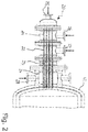
- FIG. 2 shows a burner furnace system without a pilot burner according to an embodiment according to the first aspect of the present invention. Pilot burner and main burner are combined into a new burner 20 with the synergistic effect that the part of the burner 20 used for preheating the furnace 40 can also be used for part load and full load operation during normal operation.
- the burner 20 for combusting hydrogen sulphide with oxygen is connected to the furnace 40.
- the burner 20 comprises (as an integrated pilot burner) a first port 25 connected to a plurality of first tubes 21 extending to the burner outlet.
- the burner 20 comprises (as a main burner part) a second port 26 connected to a plurality of second tubes 22 spaced from and coaxial with the first tubes 21, and a third port 27 connected to a plurality of third tubes 23 spaced from and coaxial with the second tubes 22.
- First, second, and third tubes 21, 22, 23 thus form a tube-in-tube-in-tube arrangement.
- burner 20 comprises a fourth port 28, the fourth port 28 being connected with a fourth tube 24, i.e. a pipe 24 surrounding the third tubes 23.
- the pipe 24 is connected to the entrance of the furnace 40.
- furnace 40 is first preheated to a temperature at which normal operation can be started.
- a first fuel gas preferably natural gas
- a first oxidant gas preferably air is supplied through the second port 26 and thus conducted through the second tubes 22 which are spaced from and coaxial with the first tubes 21.
- a second oxidant gas air is supplied through the third port 27 and thus conducted through the third tubes 23 which are spaced from and coaxial with the second tubes 22.
- a fuel gas flow surrounded by an oxidant gas/air flow, which is surrounded by another oxidant gas/air flow is thus formed and enters the furnace 40 where the resultant flows are mixed and combusted.
- the power of preheating can be increased in an intermediate step by supplying a fuel gas, preferably acid gas, through the first and third ports 25 and 27 of the burner 20, while supplying oxidant gas, preferably air, through the second (and fourth) ports 26, 28 of the burner 20.
- a fuel gas preferably acid gas
- oxidant gas preferably air
- acid gas is supplied through the first port 25 and thus conducted through the first tubes 21, and as a third oxidant gas, oxygen or oxygen-enriched air is supplied through the second port 26 and thus conducted through the second tubes 22, and as a fourth fuel gas, acid gas is supplied through the third port 27 and thus conducted through the third tubes 23.
- port 25 and first tubes 21 do not only have the function of enabling the preheating step but also support the main operation of the burner.
- the "pilot burner” 25, 21 can be retro-fitted into a burner 10 according to the prior art (see Figure 1 ) and can remain in the main burner and has not to be removed after start-up.
- the capacity of the pilot burner part 25, 21 can be used for the main burner part without the need of two separate units.
- a fourth port 28 can be provided which is connected with a fourth tube or pipe 24 surrounding the third tubes 23. This option was already discussed above, also in connection with Figure 1 .
- FIG. 3 shows an embodiment of another burner 30 according to the second aspect of the present invention.
- the burner 30 shown in Figure 3 is connected with its outlet to the furnace 40 and comprises an integrated pilot burner, in particular a first port 35 connected to one first tube 31 extending to the burner outlet.
- the burner 30 further comprises a second port 36 connected to a plurality of second tubes 32 and a third port 37 connected to a plurality of third tubes 33 spaced from and coaxial with the second tubes 32.
- Second and third tubes 32 and 33 form a tube-in-tube arrangement extending to the burner outlet.
- the number, orientation and distribution of the second and third tubes 32, 33 can be the same as in Figure 2 .
- a fourth port 38 can be provided which is connected with a fourth tube or pipe 34 surrounding the third tubes 33.
- first mixture of oxidant gas and fuel gas natural gas and air are supplied through first port 35 of the burner 30 and thus conducted through the first tube 31 up to the burner outlet and into the furnace 40 where the mixture is ignited for preheating the vessel of the furnace 40.
- oxidant gases preferably air
- the number of first tubes 31 can be increased.
- a first oxidant gas preferably oxygen or oxygen-enriched air is supplied through the second port 36 of the burner 30 and thus conducted through the second tubes 32 extending to the burner outlet
- an hydrogen sulphide containing gas acid gas is supplied to the first and third ports 35 and 37 of the burner 30 and thus conducted through the first and third tubes 31 and 33.
Landscapes
- Chemical & Material Sciences (AREA)
- Engineering & Computer Science (AREA)
- Combustion & Propulsion (AREA)
- Organic Chemistry (AREA)
- Chemical Kinetics & Catalysis (AREA)
- Inorganic Chemistry (AREA)
- Mechanical Engineering (AREA)
- General Engineering & Computer Science (AREA)
Priority Applications (2)
| Application Number | Priority Date | Filing Date | Title |
|---|---|---|---|
| EP18020148.5A EP3553378A1 (fr) | 2018-04-13 | 2018-04-13 | Procédé et brûleur pour la combustion d'hydrogène sulfuré |
| CN201910294041.9A CN110371931A (zh) | 2018-04-13 | 2019-04-12 | 用于燃烧硫化氢的方法和燃烧器 |
Applications Claiming Priority (1)
| Application Number | Priority Date | Filing Date | Title |
|---|---|---|---|
| EP18020148.5A EP3553378A1 (fr) | 2018-04-13 | 2018-04-13 | Procédé et brûleur pour la combustion d'hydrogène sulfuré |
Publications (1)
| Publication Number | Publication Date |
|---|---|
| EP3553378A1 true EP3553378A1 (fr) | 2019-10-16 |
Family
ID=62001937
Family Applications (1)
| Application Number | Title | Priority Date | Filing Date |
|---|---|---|---|
| EP18020148.5A Withdrawn EP3553378A1 (fr) | 2018-04-13 | 2018-04-13 | Procédé et brûleur pour la combustion d'hydrogène sulfuré |
Country Status (2)
| Country | Link |
|---|---|
| EP (1) | EP3553378A1 (fr) |
| CN (1) | CN110371931A (fr) |
Citations (7)
| Publication number | Priority date | Publication date | Assignee | Title |
|---|---|---|---|---|
| EP0315225A1 (fr) | 1987-10-16 | 1989-05-10 | Metallgesellschaft Ag | Procédé de combustion d'un gaz contenant du sulfure d'hydrogène |
| US4988287A (en) * | 1989-06-20 | 1991-01-29 | Phillips Petroleum Company | Combustion apparatus and method |
| US6893620B2 (en) | 2000-09-07 | 2005-05-17 | The Boc Group Plc | Process and apparatus for recovering sulphur from a gas stream containing hydrogen sulphide |
| US6919059B2 (en) | 2000-09-07 | 2005-07-19 | The Boc Group Plc | Process and apparatus for recovering sulphur from a gas stream containing sulphide |
| GB2467930A (en) | 2009-02-19 | 2010-08-25 | Linde Ag | An apparatus and method for forming sulphur from hydrogen sulphide |
| US20150111159A1 (en) * | 2012-06-05 | 2015-04-23 | Loesche Gmbh | Method for operating a multi-gas burner and a multi-gas burner |
| CN106765101A (zh) * | 2016-12-05 | 2017-05-31 | 东北大学 | 一种多喷嘴直接火焰冲击加热烧嘴 |
-
2018
- 2018-04-13 EP EP18020148.5A patent/EP3553378A1/fr not_active Withdrawn
-
2019
- 2019-04-12 CN CN201910294041.9A patent/CN110371931A/zh active Pending
Patent Citations (7)
| Publication number | Priority date | Publication date | Assignee | Title |
|---|---|---|---|---|
| EP0315225A1 (fr) | 1987-10-16 | 1989-05-10 | Metallgesellschaft Ag | Procédé de combustion d'un gaz contenant du sulfure d'hydrogène |
| US4988287A (en) * | 1989-06-20 | 1991-01-29 | Phillips Petroleum Company | Combustion apparatus and method |
| US6893620B2 (en) | 2000-09-07 | 2005-05-17 | The Boc Group Plc | Process and apparatus for recovering sulphur from a gas stream containing hydrogen sulphide |
| US6919059B2 (en) | 2000-09-07 | 2005-07-19 | The Boc Group Plc | Process and apparatus for recovering sulphur from a gas stream containing sulphide |
| GB2467930A (en) | 2009-02-19 | 2010-08-25 | Linde Ag | An apparatus and method for forming sulphur from hydrogen sulphide |
| US20150111159A1 (en) * | 2012-06-05 | 2015-04-23 | Loesche Gmbh | Method for operating a multi-gas burner and a multi-gas burner |
| CN106765101A (zh) * | 2016-12-05 | 2017-05-31 | 东北大学 | 一种多喷嘴直接火焰冲击加热烧嘴 |
Also Published As
| Publication number | Publication date |
|---|---|
| CN110371931A (zh) | 2019-10-25 |
Similar Documents
| Publication | Publication Date | Title |
|---|---|---|
| EP3573925B1 (fr) | Systèmes et méthodes pour améliorer l'utilisation de gaz naturel dans des vaporeformeurs de méthane | |
| JP6449300B2 (ja) | 最適化されたエネルギー回収を伴う燃焼方法および設備 | |
| DK2445830T3 (en) | Primary reforms with variable exhaust gas stream | |
| KR101227864B1 (ko) | 순산소 연소 순환 유동층 반응기와 상기 반응기를 작동시키는 방법 | |
| US4706612A (en) | Turbine exhaust fed low NOx staged combustor for TEOR power and steam generation with turbine exhaust bypass to the convection stage | |
| EA025821B1 (ru) | Топочная система и способы ее применения | |
| US20090263682A1 (en) | Fuel cell system and method for the operation of a reformer | |
| JP2003518604A (ja) | 硫化水素の部分的酸化 | |
| KR101706053B1 (ko) | 고로 열풍로 가열 방법 | |
| US20170362122A1 (en) | Direct-fired inclined counterflow rotary kilns and use thereof | |
| EP3553378A1 (fr) | Procédé et brûleur pour la combustion d'hydrogène sulfuré | |
| JP6585055B2 (ja) | 熱回収が改善された燃焼 | |
| US20180230047A1 (en) | Fiberglass material manufacture method comprising steps of sizing and desizing, and facility suitable for implementing said method | |
| RU2657561C2 (ru) | Способ сжигания низкосортного топлива | |
| US6312651B1 (en) | Apparatus for burning a combustible gas containing hydrogen sulfide | |
| US9321643B2 (en) | Process for producing synthesis gas with preservation of the energy transfer by means of the fumes | |
| WO2021079689A1 (fr) | Dispositif de reformage et système de reformage | |
| EP2868635B1 (fr) | Refroidisseur de clinker de ciment et procédé de refroidissement de clinker de ciment | |
| RU2558175C2 (ru) | Способ сжигания низкокачественного топлива | |
| US6814568B2 (en) | Superatmospheric combustor for combusting lean concentrations of a burnable gas | |
| EP4361095A1 (fr) | Procédé et appareil pour fournir de la chaleur | |
| HUE034250T2 (en) | Radiant heating pipe burner with external and internal recuperation | |
| JP2003194328A (ja) | リジェネレイティブバーナの燃焼方法及びリジェネレイティブバーナ | |
| JPS60131807A (ja) | ウエツト酸素雰囲気生成装置 | |
| JPS59159924A (ja) | 燃焼加熱炉とそれを利用した無酸化加熱法 |
Legal Events
| Date | Code | Title | Description |
|---|---|---|---|
| PUAI | Public reference made under article 153(3) epc to a published international application that has entered the european phase |
Free format text: ORIGINAL CODE: 0009012 |
|
| AK | Designated contracting states |
Kind code of ref document: A1 Designated state(s): AL AT BE BG CH CY CZ DE DK EE ES FI FR GB GR HR HU IE IS IT LI LT LU LV MC MK MT NL NO PL PT RO RS SE SI SK SM TR |
|
| AX | Request for extension of the european patent |
Extension state: BA ME |
|
| RAP1 | Party data changed (applicant data changed or rights of an application transferred) |
Owner name: LINDE GMBH |
|
| STAA | Information on the status of an ep patent application or granted ep patent |
Free format text: STATUS: THE APPLICATION IS DEEMED TO BE WITHDRAWN |
|
| 18D | Application deemed to be withdrawn |
Effective date: 20200603 |