EP3553369A1 - Beleuchtungssystem, insbesondere für kraftfahrzeug - Google Patents
Beleuchtungssystem, insbesondere für kraftfahrzeug Download PDFInfo
- Publication number
- EP3553369A1 EP3553369A1 EP19174487.9A EP19174487A EP3553369A1 EP 3553369 A1 EP3553369 A1 EP 3553369A1 EP 19174487 A EP19174487 A EP 19174487A EP 3553369 A1 EP3553369 A1 EP 3553369A1
- Authority
- EP
- European Patent Office
- Prior art keywords
- module
- lighting system
- support
- optical
- armature
- Prior art date
- Legal status (The legal status is an assumption and is not a legal conclusion. Google has not performed a legal analysis and makes no representation as to the accuracy of the status listed.)
- Withdrawn
Links
Images

Classifications
-
- F—MECHANICAL ENGINEERING; LIGHTING; HEATING; WEAPONS; BLASTING
- F21—LIGHTING
- F21V—FUNCTIONAL FEATURES OR DETAILS OF LIGHTING DEVICES OR SYSTEMS THEREOF; STRUCTURAL COMBINATIONS OF LIGHTING DEVICES WITH OTHER ARTICLES, NOT OTHERWISE PROVIDED FOR
- F21V17/00—Fastening of component parts of lighting devices, e.g. shades, globes, refractors, reflectors, filters, screens, grids or protective cages
- F21V17/005—Fastening of component parts of lighting devices, e.g. shades, globes, refractors, reflectors, filters, screens, grids or protective cages with keying means, i.e. for enabling the assembling of component parts in distinctive positions, e.g. for preventing wrong mounting
-
- F—MECHANICAL ENGINEERING; LIGHTING; HEATING; WEAPONS; BLASTING
- F21—LIGHTING
- F21S—NON-PORTABLE LIGHTING DEVICES; SYSTEMS THEREOF; VEHICLE LIGHTING DEVICES SPECIALLY ADAPTED FOR VEHICLE EXTERIORS
- F21S41/00—Illuminating devices specially adapted for vehicle exteriors, e.g. headlamps
- F21S41/10—Illuminating devices specially adapted for vehicle exteriors, e.g. headlamps characterised by the light source
- F21S41/14—Illuminating devices specially adapted for vehicle exteriors, e.g. headlamps characterised by the light source characterised by the type of light source
- F21S41/141—Light emitting diodes [LED]
- F21S41/143—Light emitting diodes [LED] the main emission direction of the LED being parallel to the optical axis of the illuminating device
-
- F—MECHANICAL ENGINEERING; LIGHTING; HEATING; WEAPONS; BLASTING
- F21—LIGHTING
- F21S—NON-PORTABLE LIGHTING DEVICES; SYSTEMS THEREOF; VEHICLE LIGHTING DEVICES SPECIALLY ADAPTED FOR VEHICLE EXTERIORS
- F21S41/00—Illuminating devices specially adapted for vehicle exteriors, e.g. headlamps
- F21S41/10—Illuminating devices specially adapted for vehicle exteriors, e.g. headlamps characterised by the light source
- F21S41/14—Illuminating devices specially adapted for vehicle exteriors, e.g. headlamps characterised by the light source characterised by the type of light source
- F21S41/141—Light emitting diodes [LED]
- F21S41/151—Light emitting diodes [LED] arranged in one or more lines
- F21S41/153—Light emitting diodes [LED] arranged in one or more lines arranged in a matrix
-
- F—MECHANICAL ENGINEERING; LIGHTING; HEATING; WEAPONS; BLASTING
- F21—LIGHTING
- F21S—NON-PORTABLE LIGHTING DEVICES; SYSTEMS THEREOF; VEHICLE LIGHTING DEVICES SPECIALLY ADAPTED FOR VEHICLE EXTERIORS
- F21S41/00—Illuminating devices specially adapted for vehicle exteriors, e.g. headlamps
- F21S41/10—Illuminating devices specially adapted for vehicle exteriors, e.g. headlamps characterised by the light source
- F21S41/19—Attachment of light sources or lamp holders
- F21S41/192—Details of lamp holders, terminals or connectors
-
- F—MECHANICAL ENGINEERING; LIGHTING; HEATING; WEAPONS; BLASTING
- F21—LIGHTING
- F21S—NON-PORTABLE LIGHTING DEVICES; SYSTEMS THEREOF; VEHICLE LIGHTING DEVICES SPECIALLY ADAPTED FOR VEHICLE EXTERIORS
- F21S41/00—Illuminating devices specially adapted for vehicle exteriors, e.g. headlamps
- F21S41/20—Illuminating devices specially adapted for vehicle exteriors, e.g. headlamps characterised by refractors, transparent cover plates, light guides or filters
- F21S41/29—Attachment thereof
-
- F—MECHANICAL ENGINEERING; LIGHTING; HEATING; WEAPONS; BLASTING
- F21—LIGHTING
- F21S—NON-PORTABLE LIGHTING DEVICES; SYSTEMS THEREOF; VEHICLE LIGHTING DEVICES SPECIALLY ADAPTED FOR VEHICLE EXTERIORS
- F21S41/00—Illuminating devices specially adapted for vehicle exteriors, e.g. headlamps
- F21S41/60—Illuminating devices specially adapted for vehicle exteriors, e.g. headlamps characterised by a variable light distribution
- F21S41/65—Illuminating devices specially adapted for vehicle exteriors, e.g. headlamps characterised by a variable light distribution by acting on light sources
- F21S41/663—Illuminating devices specially adapted for vehicle exteriors, e.g. headlamps characterised by a variable light distribution by acting on light sources by switching light sources
-
- F—MECHANICAL ENGINEERING; LIGHTING; HEATING; WEAPONS; BLASTING
- F21—LIGHTING
- F21S—NON-PORTABLE LIGHTING DEVICES; SYSTEMS THEREOF; VEHICLE LIGHTING DEVICES SPECIALLY ADAPTED FOR VEHICLE EXTERIORS
- F21S41/00—Illuminating devices specially adapted for vehicle exteriors, e.g. headlamps
- F21S41/20—Illuminating devices specially adapted for vehicle exteriors, e.g. headlamps characterised by refractors, transparent cover plates, light guides or filters
- F21S41/25—Projection lenses
- F21S41/255—Lenses with a front view of circular or truncated circular outline
-
- F—MECHANICAL ENGINEERING; LIGHTING; HEATING; WEAPONS; BLASTING
- F21—LIGHTING
- F21S—NON-PORTABLE LIGHTING DEVICES; SYSTEMS THEREOF; VEHICLE LIGHTING DEVICES SPECIALLY ADAPTED FOR VEHICLE EXTERIORS
- F21S45/00—Arrangements within vehicle lighting devices specially adapted for vehicle exteriors, for purposes other than emission or distribution of light
- F21S45/40—Cooling of lighting devices
- F21S45/49—Attachment of the cooling means
-
- F—MECHANICAL ENGINEERING; LIGHTING; HEATING; WEAPONS; BLASTING
- F21—LIGHTING
- F21Y—INDEXING SCHEME ASSOCIATED WITH SUBCLASSES F21K, F21L, F21S and F21V, RELATING TO THE FORM OR THE KIND OF THE LIGHT SOURCES OR OF THE COLOUR OF THE LIGHT EMITTED
- F21Y2103/00—Elongate light sources, e.g. fluorescent tubes
- F21Y2103/10—Elongate light sources, e.g. fluorescent tubes comprising a linear array of point-like light-generating elements
-
- F—MECHANICAL ENGINEERING; LIGHTING; HEATING; WEAPONS; BLASTING
- F21—LIGHTING
- F21Y—INDEXING SCHEME ASSOCIATED WITH SUBCLASSES F21K, F21L, F21S and F21V, RELATING TO THE FORM OR THE KIND OF THE LIGHT SOURCES OR OF THE COLOUR OF THE LIGHT EMITTED
- F21Y2115/00—Light-generating elements of semiconductor light sources
- F21Y2115/10—Light-emitting diodes [LED]
Definitions
- the present invention relates to a lighting system, in particular for a motor vehicle.
- each of the modules and in particular each of their components are specifically configured, which generates a great complexity and a low level of standardization.
- the objective of the invention is to overcome at least part of the aforementioned disadvantages and proposes for this purpose a lighting system, in particular for a motor vehicle, comprising at least two optical modules, each optical module comprising one or more light sources, a component optical device associated with said light source (s), a support for said light source (s) and an armature support of said support, said support being identical from one module to another, said support frames being respectively configured to receive the associated optical component so that an optical axis of said component is positioned differently from the associated light source or sources, from one module to another.
- the invention thus makes it possible to standardize at least one of the components of the modules, namely the support of the light source or sources, which is a particularly judicious choice, in particular when one seeks to obtain an interlacing of the light beams. emitted since the number and the nature of the light sources are then advantageously identical from one module to another.
- support frames are intended to present other differences from one module to another. The invention thus makes it possible to concentrate the configuration specificities on the single piece.
- the invention also relates to a support frame for a lighting system as described above, said support frame being configured so that the optical axis of the associated optical component is off-axis with respect to said one or more light sources.
- the invention also relates to a projector comprising such a lighting system.
- the invention relates to a lighting system, in particular for a motor vehicle, comprising at least two optical modules 100, 200 partially shown in this figure.
- Each optical module comprises one or more light sources 102, 202, here seven. These are, for example, light-emitting semiconductor chips, in particular light-emitting diodes. They are advantageously the same number from one module to another.
- the light sources 102, 202 are aligned. They may be regularly spaced from each other by a step p, following the direction of alignment, according to a spacing e. Said light sources 102, 202 here all have the same width l along the alignment direction, the distance e being less than the width l. Said light sources 102, 202 are optionally identical to each other.
- Each module further comprises an optical component 104, 204, associated with said light source or sources 102, 202.
- Each of said optical components 104, 204 has an optical axis 106, 206.
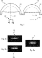
- each module 100, 200 is advantageously capable of emitting a partial light beam composed of a plurality of vertical-cut light spots 108, 208, each formed by the optical component of the module from the light emitted by the source or sources of light of said module.
- a partial light beam composed of a plurality of vertical-cut light spots 108, 208, each formed by the optical component of the module from the light emitted by the source or sources of light of said module.
- seven light spots 108, 208 formed by each of the modules from each of its light sources 102, 202.
- Each of the spots 108, 208 can illuminate a specific area, particularly in front of the vehicle when said lighting system is used as a motor vehicle headlamp. When a vehicle followed or crossed enters one or other of these areas, it dazzles its occupants by modulating the lighting intensity, or even turning off the lighting of the area concerned, this while maintaining maximum lighting in other areas. This optimizes the vision available to the driver of the equipped vehicle without disturbing the occupants of other vehicles.
- each module the light sources 102, 202 may be selectively activatable.
- the optical component 104, 204 of each module is arranged to form a light spot having two vertical cuts, in particular of generally rectangular shape, from the light emitted by each light source and to project this light. bright spot on the road.
- the resulting beam 1 emitted by the system comes from the combination of the partial beams emitted by each of the modules 100, 200. It is found that it provides a more uniform illumination than each of the partial beams in which each of the spots 108, 208 are separated by unenlightened dark areas.
- said modules 100, 200 are advantageously configured so that each light spot 108 of the partial beam emitted by the 100 optical modules is superimposed on at least one light spot 208 of the partial beam emitted by the other optical module 200, so as to form an interlacing of these partial beams.
- the optical axes 106, 206 of the components 104, 204 are positioned differently from the said associated light source (s) from one module 100 to the other 200. It is then understood that to obtain a non When illuminated, it will be necessary to deactivate at least one of the light sources 108 of one of the modules 100 and at least one neighbor of the light sources 208 of the other 200 of the modules. The strategy is the same when one wishes to obtain a decrease of intensity of the lighting of said zone.
- said optical axes 106, 206 are advantageously parallel to each other.
- each of the modules 100, 200 further comprises a support 110, 210 of the at least one light source 102, 202 and a support frame 112, 212 of said support 110, 210.
- said supports 110, 210 are identical from one module to another, which makes it possible to be able to use one and the same assembly formed of said support and of said source or sources of light for all the modules, as illustrated by the arrow 2 which doubles up from the figure 4 .
- said support armatures 112, 212 are respectively configured to receive the associated optical component 104, 204 so that the optical axis 106, 206 of said component 104, 204 is positioned differently from the said associated light source (s) 102, 202, from one module 100 to the other 200.
- the positioning of the optical axes 106, 206 relative to the said source (s) associated light 102, 202 differs from one module to another not by the location of the light source or sources 102, 202 on their respective support 110, 210 but through the configuration of said support frames 112, 212 .
- said support armature 112 of a first of said modules is configured in such a way that the optical axis 106 of the optical component 104 intended to be associated with said first armature 112 is centered on the or the light sources 102 of said first module.
- it is therefore located on the light-emitting diode lying in the middle of the others, being positioned in the center of the light emitting surface of said diode.
- said support armature 212 of a second of said modules is configured in such a way that the optical axis 206 of the optical component 204 intended to be associated with said second armature 212 is off-axis with respect to the light source or sources 202 of the second module.
- said first armature 112 and said second armature 212 support are configured to obtain the optical beam interleaving mentioned above.
- said first frame 112 and said second support frame 212 are configured so that each light spot 108 of the partial beam emitted by the first optical module is superimposed on at least one light spot 208 of the partial beam emitted by the second module.
- the support frame 212 of the second module is configured so that the optical axis 206 of the associated optical component 204 is shifted by a distance of p / 2 along said alignment direction of the light sources 202.
- optical component 104, 204 of each module is a lens, preferably identical from one module to the other at least in its portion providing an optical function.
- Said support frames 112, 212 each comprise a mounting plate 114, 214 of the associated optical component 104, 204.
- Said platinum is, for example, molded. It is here in the shape of a bowl.
- Said support frames 112, 212 receive the support 110, 210 associated on an outer face of a bottom 115, 215 of said bowl, for example substantially in the center of said bottom.
- Said support frames 112, 212 comprise pins 116, 216 for placing the supports 110, 210 of the light source or sources 102, 202. These positioning pins extend from said fixing plate 114, 214, here bottom 115, 215 of the bowl forming said platen. They are, for example, made from material of said plate 114, 214.
- Each fixing plate 114, 214 may further comprise one or more flanges 118, 218 for placing said associated optical component 104, 204.
- the or said positioning flanges 118, 218 are located on a face of the plates opposite one face of said plates provided with said pins 116, 216. They comprise here olbic panels, located at side flanks 120, 220 of said bowl.
- the one or more flanges 118, 218 are positioned differently with respect to said pins 116, 216 from one module to another. They may have a different configuration from one module to another so as to accommodate separate optical components.
- Said plates may also include one or more attachment brackets 122, 222 of the support frame to a support of said lighting system. They extend here laterally from said lateral flanks 120, 220.
- Said support 10 comprises, for example, a printed circuit board 12.
- said card 12 may be used to supply current to said light source or sources 2. It comprises, for example, a control unit 14 and / or a connection flange 16.
- Said card 12 further comprises a plurality of orifices, starting with first orifices 18, intended to cooperate with said pins 116, 216 of each of the modules.
- Said first orifices 18 are here two in number. One of them is oblong. They are located on either side of said light sources 2. Said first orifices 18 are advantageously substantially aligned with said light source or sources.
- Said card 12 may further comprise second orifices 20 for attachment to said support frames and / or third orifices 22 for fixing a heat dissipating member.
- Said first, second and third orifices are here arranged in two rows, respectively located along two edges of the card 12.
- Said second orifices are four in number and are located at the ends of each row.
- Said third orifices are two in number, one in each row, and are located between one of the first orifices 18 and one of the second orifices 20.
- Said light sources 2 are centered between the two rows.
- the relative positioning of said pins 116, 216 with respect to the light source or sources 102, 202 is identical from one module to the other and the relative positioning of the first orifices 18 with respect to the light source or sources 102, 202 is identical from one module to the other.
- said support frames 112, 212 are configured so that the optical axis 106, 206 of said components 104, 204 is positioned differently with respect to said pins 116, 216 from one module to another.
- the lighting system may further comprise control means for switching on, off or modifying the light power emitted by the light sources of the light modules, for example integrated in said control unit 14.
- the lighting system may also comprise a detection module on the road of a body not to dazzle, said detection module being able to send a detection information to said control means which turn on, off or modify the light power emitted by the light sources of the light modules according to this detection information.
- the invention also relates to a support frame for a lighting system as described above, said support frame being configured so that the optical axis of the associated optical component is off-axis with respect to said one or more light sources.
- the invention also relates to a projector comprising a lighting system as described above.
- Said projector comprises, for example, a housing inside which said system is reported and a transparent glass closing said housing.
Landscapes
- Engineering & Computer Science (AREA)
- General Engineering & Computer Science (AREA)
- Physics & Mathematics (AREA)
- Microelectronics & Electronic Packaging (AREA)
- Optics & Photonics (AREA)
- Mathematical Physics (AREA)
- Non-Portable Lighting Devices Or Systems Thereof (AREA)
Applications Claiming Priority (2)
| Application Number | Priority Date | Filing Date | Title |
|---|---|---|---|
| FR1558519A FR3041078B1 (fr) | 2015-09-14 | 2015-09-14 | Systeme d'eclairage, notamment pour vehicule automobile |
| EP16187989.5A EP3141805B1 (de) | 2015-09-14 | 2016-09-09 | Beleuchtungssystem, insbesondere für kraftfahrzeug |
Related Parent Applications (1)
| Application Number | Title | Priority Date | Filing Date |
|---|---|---|---|
| EP16187989.5A Division EP3141805B1 (de) | 2015-09-14 | 2016-09-09 | Beleuchtungssystem, insbesondere für kraftfahrzeug |
Publications (1)
| Publication Number | Publication Date |
|---|---|
| EP3553369A1 true EP3553369A1 (de) | 2019-10-16 |
Family
ID=54545311
Family Applications (2)
| Application Number | Title | Priority Date | Filing Date |
|---|---|---|---|
| EP19174487.9A Withdrawn EP3553369A1 (de) | 2015-09-14 | 2016-09-09 | Beleuchtungssystem, insbesondere für kraftfahrzeug |
| EP16187989.5A Active EP3141805B1 (de) | 2015-09-14 | 2016-09-09 | Beleuchtungssystem, insbesondere für kraftfahrzeug |
Family Applications After (1)
| Application Number | Title | Priority Date | Filing Date |
|---|---|---|---|
| EP16187989.5A Active EP3141805B1 (de) | 2015-09-14 | 2016-09-09 | Beleuchtungssystem, insbesondere für kraftfahrzeug |
Country Status (2)
| Country | Link |
|---|---|
| EP (2) | EP3553369A1 (de) |
| FR (1) | FR3041078B1 (de) |
Families Citing this family (1)
| Publication number | Priority date | Publication date | Assignee | Title |
|---|---|---|---|---|
| EP3786518A1 (de) * | 2019-08-27 | 2021-03-03 | Seoul Semiconductor Europe GmbH | Beleuchtungsvorrichtung |
Citations (8)
| Publication number | Priority date | Publication date | Assignee | Title |
|---|---|---|---|---|
| EP1980786A1 (de) * | 2007-04-10 | 2008-10-15 | Koito Manufacturing Co., Ltd | Fahrzeugbeleuchtungseinheit |
| EP2280215A2 (de) * | 2009-07-31 | 2011-02-02 | Zizala Lichtsysteme GmbH | LED-Kraftfahrzeugscheinwerfer zur Erzeugung einer dynamischen Lichtverteilung |
| US20110235349A1 (en) * | 2010-03-25 | 2011-09-29 | Yoshiaki Nakaya | Vehicle light and method for controlling light distribution |
| US20140117386A1 (en) * | 2011-02-04 | 2014-05-01 | Cree, Inc. | Tilted emission led array |
| US20140169014A1 (en) * | 2011-08-08 | 2014-06-19 | Zizala Lichtsysteme Gmbh | Led light-source module for a vehicle headlight |
| US20140204602A1 (en) * | 2011-08-08 | 2014-07-24 | Zizala Lichtsysteme Gmbh | Led light-source module for an led motor vehicle headlight |
| WO2014124477A1 (de) * | 2013-02-14 | 2014-08-21 | Zizala Lichtsysteme Gmbh | Lichtmodul für einen fahrzeugscheinwerfer |
| US20150062919A1 (en) * | 2013-09-05 | 2015-03-05 | Ford Global Technologies, Llc | Optical lens positioning system and method |
-
2015
- 2015-09-14 FR FR1558519A patent/FR3041078B1/fr active Active
-
2016
- 2016-09-09 EP EP19174487.9A patent/EP3553369A1/de not_active Withdrawn
- 2016-09-09 EP EP16187989.5A patent/EP3141805B1/de active Active
Patent Citations (8)
| Publication number | Priority date | Publication date | Assignee | Title |
|---|---|---|---|---|
| EP1980786A1 (de) * | 2007-04-10 | 2008-10-15 | Koito Manufacturing Co., Ltd | Fahrzeugbeleuchtungseinheit |
| EP2280215A2 (de) * | 2009-07-31 | 2011-02-02 | Zizala Lichtsysteme GmbH | LED-Kraftfahrzeugscheinwerfer zur Erzeugung einer dynamischen Lichtverteilung |
| US20110235349A1 (en) * | 2010-03-25 | 2011-09-29 | Yoshiaki Nakaya | Vehicle light and method for controlling light distribution |
| US20140117386A1 (en) * | 2011-02-04 | 2014-05-01 | Cree, Inc. | Tilted emission led array |
| US20140169014A1 (en) * | 2011-08-08 | 2014-06-19 | Zizala Lichtsysteme Gmbh | Led light-source module for a vehicle headlight |
| US20140204602A1 (en) * | 2011-08-08 | 2014-07-24 | Zizala Lichtsysteme Gmbh | Led light-source module for an led motor vehicle headlight |
| WO2014124477A1 (de) * | 2013-02-14 | 2014-08-21 | Zizala Lichtsysteme Gmbh | Lichtmodul für einen fahrzeugscheinwerfer |
| US20150062919A1 (en) * | 2013-09-05 | 2015-03-05 | Ford Global Technologies, Llc | Optical lens positioning system and method |
Also Published As
| Publication number | Publication date |
|---|---|
| EP3141805B1 (de) | 2019-05-15 |
| FR3041078B1 (fr) | 2021-01-15 |
| EP3141805A1 (de) | 2017-03-15 |
| FR3041078A1 (fr) | 2017-03-17 |
Similar Documents
| Publication | Publication Date | Title |
|---|---|---|
| EP3067618B1 (de) | Leuchtvorrichtung mit optischen wellenleitern | |
| EP2607165B1 (de) | Beleuchtungsmodul mit zumindest zwei im wesentlich senkrecht zueinander angeordneten Lichtquellen | |
| EP3537040B1 (de) | Leuchtmodul und leuchtvorrichtung für kraftfahrzeug, das ein solches leuchtmodul umfasst | |
| EP4579123A2 (de) | Leuchtmodul zur beleuchtung eines kraftfahrzeugs | |
| FR2995967B1 (fr) | Module d'eclairage, notamment pour vehicule automobile | |
| EP2966343B1 (de) | Beleuchtungsmodul für autoscheinwerfer mit positioniermittel zwischen kühlkörper und reflektor/leiterplatte | |
| EP3093557A1 (de) | Beleuchtungsmodul mit doppelfunktion für abblend- und fernlicht für kraftfahrzeug | |
| EP3210828A1 (de) | Beleuchtungssystem für den fahrzeuginnenraum eines kraftfahrzeugs | |
| FR3056700A1 (fr) | Module d'eclairage optique, notamment pour un vehicule automobile | |
| FR2998352A1 (fr) | Dispositifs d'eclairage et/ou de signalisation pour vehicule automobile | |
| EP3030830B1 (de) | Signalisierungs- und/oder beleuchtungsvorrichtung für kraftfahrzeuge | |
| EP3224083A1 (de) | Fahrzeugscheinwerfer | |
| EP2816277B1 (de) | Beleuchtungsvorrichtung eines Fahrzeugs, die eine optische Multifunktionslinse verwendet | |
| EP3141805B1 (de) | Beleuchtungssystem, insbesondere für kraftfahrzeug | |
| FR2979971A1 (fr) | Dispositif d'eclairage et/ou de signalisation pour vehicule automobile | |
| EP2980470A1 (de) | Leuchtsystem, insbesondere für kraftfahrzeug | |
| FR3052535A1 (fr) | Module optique pour dispositif d'eclairage de vehicule automobile | |
| FR3087395A1 (fr) | Dispositif d’eclairage avant pour vehicule automobile | |
| FR3103252A1 (fr) | Module d’eclairage pour vehicule a coupure modulable entre conduite a gauche et conduite a droite | |
| EP3104065B1 (de) | Signal- und/oder beleuchtungsvorrichtung eines kraftfahrzeugs | |
| FR3165056A1 (fr) | Dispositif lumineux pour véhicule automobile muni de deux modules lumineux réalisant des fonctions d’écriture sur route | |
| FR3137435A1 (fr) | Module lumineux comprenant au moins deux sources lumineuses dont les axes optiques respectifs sont sécants. | |
| FR3151379A1 (fr) | Dispositif lumineux d’éclairage et/ou de signalisation d’un véhicule automobile | |
| EP3221185B1 (de) | Leuchteinheit für ein fahrzeug und dazugehöriges fahrzeug | |
| FR3038694A1 (fr) | Dispositif lumineux configure pour emettre un faisceau lumineux segmente, notamment pour vehicule automobile, et projecteur muni d'un tel dispositif. |
Legal Events
| Date | Code | Title | Description |
|---|---|---|---|
| PUAI | Public reference made under article 153(3) epc to a published international application that has entered the european phase |
Free format text: ORIGINAL CODE: 0009012 |
|
| STAA | Information on the status of an ep patent application or granted ep patent |
Free format text: STATUS: THE APPLICATION HAS BEEN PUBLISHED |
|
| AC | Divisional application: reference to earlier application |
Ref document number: 3141805 Country of ref document: EP Kind code of ref document: P |
|
| AK | Designated contracting states |
Kind code of ref document: A1 Designated state(s): AL AT BE BG CH CY CZ DE DK EE ES FI FR GB GR HR HU IE IS IT LI LT LU LV MC MK MT NL NO PL PT RO RS SE SI SK SM TR |
|
| STAA | Information on the status of an ep patent application or granted ep patent |
Free format text: STATUS: REQUEST FOR EXAMINATION WAS MADE |
|
| 17P | Request for examination filed |
Effective date: 20200415 |
|
| RBV | Designated contracting states (corrected) |
Designated state(s): AL AT BE BG CH CY CZ DE DK EE ES FI FR GB GR HR HU IE IS IT LI LT LU LV MC MK MT NL NO PL PT RO RS SE SI SK SM TR |
|
| STAA | Information on the status of an ep patent application or granted ep patent |
Free format text: STATUS: EXAMINATION IS IN PROGRESS |
|
| 17Q | First examination report despatched |
Effective date: 20220222 |
|
| P01 | Opt-out of the competence of the unified patent court (upc) registered |
Effective date: 20230528 |
|
| RIC1 | Information provided on ipc code assigned before grant |
Ipc: F21S 41/255 20180101ALN20241223BHEP Ipc: F21Y 115/10 20160101ALN20241223BHEP Ipc: F21Y 103/10 20160101ALN20241223BHEP Ipc: F21S 41/663 20180101ALI20241223BHEP Ipc: F21S 41/19 20180101ALI20241223BHEP Ipc: F21S 41/143 20180101ALI20241223BHEP Ipc: F21S 41/29 20180101AFI20241223BHEP |
|
| STAA | Information on the status of an ep patent application or granted ep patent |
Free format text: STATUS: THE APPLICATION IS DEEMED TO BE WITHDRAWN |
|
| 18D | Application deemed to be withdrawn |
Effective date: 20250812 |