EP3553229B1 - Excavation device and system for monitoring a construction site - Google Patents
Excavation device and system for monitoring a construction site Download PDFInfo
- Publication number
- EP3553229B1 EP3553229B1 EP18166806.2A EP18166806A EP3553229B1 EP 3553229 B1 EP3553229 B1 EP 3553229B1 EP 18166806 A EP18166806 A EP 18166806A EP 3553229 B1 EP3553229 B1 EP 3553229B1
- Authority
- EP
- European Patent Office
- Prior art keywords
- civil engineering
- engineering device
- control unit
- camera
- construction site
- Prior art date
- Legal status (The legal status is an assumption and is not a legal conclusion. Google has not performed a legal analysis and makes no representation as to the accuracy of the status listed.)
- Active
Links
- 238000010276 construction Methods 0.000 title claims description 19
- 238000012544 monitoring process Methods 0.000 title claims description 11
- 238000009412 basement excavation Methods 0.000 title 1
- 238000013459 approach Methods 0.000 claims description 4
- 238000005553 drilling Methods 0.000 description 7
- 238000009430 construction management Methods 0.000 description 1
- 230000001419 dependent effect Effects 0.000 description 1
- 238000013461 design Methods 0.000 description 1
- 238000011161 development Methods 0.000 description 1
- 238000012806 monitoring device Methods 0.000 description 1
- 230000003287 optical effect Effects 0.000 description 1
- 230000035515 penetration Effects 0.000 description 1
- 230000001960 triggered effect Effects 0.000 description 1
Images

Classifications
-
- G—PHYSICS
- G08—SIGNALLING
- G08B—SIGNALLING OR CALLING SYSTEMS; ORDER TELEGRAPHS; ALARM SYSTEMS
- G08B13/00—Burglar, theft or intruder alarms
- G08B13/18—Actuation by interference with heat, light, or radiation of shorter wavelength; Actuation by intruding sources of heat, light, or radiation of shorter wavelength
- G08B13/189—Actuation by interference with heat, light, or radiation of shorter wavelength; Actuation by intruding sources of heat, light, or radiation of shorter wavelength using passive radiation detection systems
- G08B13/194—Actuation by interference with heat, light, or radiation of shorter wavelength; Actuation by intruding sources of heat, light, or radiation of shorter wavelength using passive radiation detection systems using image scanning and comparing systems
- G08B13/196—Actuation by interference with heat, light, or radiation of shorter wavelength; Actuation by intruding sources of heat, light, or radiation of shorter wavelength using passive radiation detection systems using image scanning and comparing systems using television cameras
- G08B13/19602—Image analysis to detect motion of the intruder, e.g. by frame subtraction
- G08B13/1961—Movement detection not involving frame subtraction, e.g. motion detection on the basis of luminance changes in the image
-
- E—FIXED CONSTRUCTIONS
- E02—HYDRAULIC ENGINEERING; FOUNDATIONS; SOIL SHIFTING
- E02D—FOUNDATIONS; EXCAVATIONS; EMBANKMENTS; UNDERGROUND OR UNDERWATER STRUCTURES
- E02D7/00—Methods or apparatus for placing sheet pile bulkheads, piles, mouldpipes, or other moulds
-
- E—FIXED CONSTRUCTIONS
- E21—EARTH OR ROCK DRILLING; MINING
- E21B—EARTH OR ROCK DRILLING; OBTAINING OIL, GAS, WATER, SOLUBLE OR MELTABLE MATERIALS OR A SLURRY OF MINERALS FROM WELLS
- E21B41/00—Equipment or details not covered by groups E21B15/00 - E21B40/00
- E21B41/0021—Safety devices, e.g. for preventing small objects from falling into the borehole
-
- E—FIXED CONSTRUCTIONS
- E21—EARTH OR ROCK DRILLING; MINING
- E21B—EARTH OR ROCK DRILLING; OBTAINING OIL, GAS, WATER, SOLUBLE OR MELTABLE MATERIALS OR A SLURRY OF MINERALS FROM WELLS
- E21B7/00—Special methods or apparatus for drilling
- E21B7/02—Drilling rigs characterised by means for land transport with their own drive, e.g. skid mounting or wheel mounting
-
- H—ELECTRICITY
- H04—ELECTRIC COMMUNICATION TECHNIQUE
- H04N—PICTORIAL COMMUNICATION, e.g. TELEVISION
- H04N23/00—Cameras or camera modules comprising electronic image sensors; Control thereof
- H04N23/50—Constructional details
- H04N23/54—Mounting of pick-up tubes, electronic image sensors, deviation or focusing coils
-
- H—ELECTRICITY
- H04—ELECTRIC COMMUNICATION TECHNIQUE
- H04N—PICTORIAL COMMUNICATION, e.g. TELEVISION
- H04N5/00—Details of television systems
- H04N5/222—Studio circuitry; Studio devices; Studio equipment
- H04N5/262—Studio circuits, e.g. for mixing, switching-over, change of character of image, other special effects ; Cameras specially adapted for the electronic generation of special effects
- H04N5/265—Mixing
-
- H—ELECTRICITY
- H04—ELECTRIC COMMUNICATION TECHNIQUE
- H04N—PICTORIAL COMMUNICATION, e.g. TELEVISION
- H04N7/00—Television systems
- H04N7/18—Closed-circuit television [CCTV] systems, i.e. systems in which the video signal is not broadcast
- H04N7/188—Capturing isolated or intermittent images triggered by the occurrence of a predetermined event, e.g. an object reaching a predetermined position
Definitions
- the invention relates to a civil engineering device with an undercarriage with crawler track, a superstructure which is arranged on the undercarriage, and a mast which is vertically directed and attached to the superstructure, according to the preamble of claim 1.
- a civil engineering device which is designed as a drilling device, is for example in the EP 2 378 054 A1
- this publication discloses a safety device for a construction machine, which takes into account the ever-increasing requirements for operational and work safety.
- This construction machine is equipped with a large number of sensors which record the respective operating status in order to avoid critical operating situations.
- the CN 205 242 405 U discloses a generic civil engineering device with a camera on a mast.
- the JP-2010 241 548 A1 does not concern a civil engineering device, but a crane for lifting and lowering a load.
- This known crane device has various cameras with which special helmets H of people on the ground can be detected.
- the detected helmets can be shown on a display that shows an operator a schematic view of the device from above with a danger zone around the suspended load.
- the EP 2 378 054 A1 discloses a construction machine with a safety device, in which a machine operator is shown the construction machine on a display device with a possible adjustment range in which an adjustment of an actuating device is possible without the risk of tipping over. There is no provision for attaching a camera to the civil engineering device.
- the invention is based on the object of specifying a civil engineering device with which improved safety can be achieved.
- a basic idea of the invention can be seen in arranging at least one camera on the mast of the civil engineering device for monitoring purposes.
- Cameras in particular electronic cameras, are generally known for monitoring purposes.
- One aspect of the invention is that in the special design of a civil engineering device, the camera is not simply arranged on the upper carriage, but above the upper carriage in an upper area of the mast of the civil engineering device.
- the camera can be arranged in a protected manner on the transverse mast head on the top or preferably on the bottom of the mast head. This positioning not only provides a good overview of the civil engineering device and the surroundings, but a camera is also arranged on the upper area of the mast in a particularly protected manner from the harsh construction site conditions.
- the image can be transmitted to a control station or to a control center, with monitoring being carried out by a person or by a computer system.
- a preferred embodiment of the invention consists in that several cameras are arranged which are aligned in different directions.
- a first camera is preferably arranged on a front side of the mast head and a second camera is arranged on the back of the mast head.
- Two cameras can also be arranged on the front and the back, with the two pairs of cameras then each being aligned to opposite sides, so that the most comprehensive image of the surroundings possible is achieved, including a top view of the civil engineering device.
- a further improvement can be achieved according to an embodiment of the invention in that at least one camera is pivotably mounted and driven. In this way, a larger observation area can be covered with one camera.
- the camera can also be adjusted and focused by a rear control unit, so that zoom settings of details of the civil engineering device or the surroundings are also possible.
- a 360° image of the surroundings can be created using at least one camera.
- these are linked to appropriate software via the control unit in such a way that a 360° image of the surroundings is composed of multiple camera settings. This makes it possible to achieve an almost complete view of the civil engineering device and a specified area around the civil engineering device from above.
- the at least one camera is connected to at least one control unit.
- the connection can be wired or preferably wireless.
- control unit is arranged in an operating station of the civil engineering device and/or remotely from the civil engineering device.
- the control unit can thus be arranged both in the operating station and in a control center, for example at the construction management of the construction site or in a control center of the construction company.
- monitoring of the civil engineering device both when it is at a standstill and when it is in operation can be carried out not only by the machine operator, but also by a decentralized monitoring point.
- the machine operator can also be supported in safety matters by a remote control center.
- the security can relate both to the actual operation of the civil engineering device and to downtimes, during which the civil engineering device is protected from theft and vandalism, for example at night.
- a warning signal can be emitted by the control unit when a person or an object approaches the civil engineering device and enters a safety area.
- a safety area with a predeterminable safety distance which can be approximately 1 to 2 m, can be stored virtually in an electronic control unit.
- the image created by the at least one camera can be monitored using appropriate image processing software, so that the control unit automatically detects when there is a possible risk of collision when the civil engineering device is moving or when a person approaches the civil engineering device when the device is at a standstill or is otherwise in operation.
- the warning signal can be displayed in a suitable manner, for example as a warning tone or as a warning light directly on the civil engineering device.
- the warning signal can cause the civil engineering device to stop operating, in particular if a person is in an internal danger zone on the civil engineering device, which can be part of the defined warning zone.
- the civil engineering device can be in particular a drilling device, in particular a pile drilling device, a diaphragm wall device, in particular a diaphragm wall cutter or a diaphragm wall grab, a vibrator and/or a ram.
- this relates to a system for monitoring a construction site, wherein several civil engineering devices according to the invention, as described above, are provided and the civil engineering devices are connected to a common control unit, by means of which the images from a single civil engineering device are combined to form an overall view of the construction site.
- the monitoring devices of several civil engineering devices can be networked and connected to one another so that an overall view of a construction site can be achieved. This enables particularly good monitoring and thus security of the individual civil engineering devices and the construction site as a whole.
- the control unit can also be equipped with a corresponding storage device with which the images of individual civil engineering devices or of all civil engineering devices can be saved. This can further increase both occupational safety and security against theft and vandalism on a construction site.
- the system according to the invention is further developed in that the control unit emits a warning signal when a person enters the safety area of the construction site.
- the control unit defines a safety area using appropriate image processing software and a safety distance specified by the operating personnel. If people enter this safety area, a corresponding warning signal can then be triggered and, if necessary, a stop to the operation of individual or all civil engineering devices and possibly other construction machines present at the construction site.
- the safety or warning area can be divided into two parts, with only a warning signal being given in an outer area and then operations being stopped in a defined inner area.
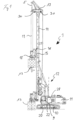
- a civil engineering device 1 is designed as a drilling device.
- the civil engineering device 1 has a carrier device 9 with an undercarriage 10, on which an upper carriage 11 with an operating station 22 and a drive unit 28 are rotatably mounted.
- a vertical mast 14 is pivotably mounted on the upper carriage 11 via a mast steering 12.
- a mast guide 16 is arranged on a front side of the mast 14, along which a mast carriage 15 with a drilling drive 18 is slidably mounted.
- the drilling drive 18 rotates a drilling tool 13, which is attached in a basically known manner to a Kelly bar 19, which in turn is vertically adjustable via a main cable 5 over a mast head 17.
- a transversely directed mast head 17 is attached to the upper end of the mast 14, on the underside of which two cameras 30 of a monitoring system according to the invention are arranged.
- the cameras 30 are directed downwards in order to generate an image 60 of the civil engineering device 1 from above, which is shown by way of example in Fig.2 is shown.
- the control unit 20 can have a monitor on which the Fig.2
- the schematically illustrated image is composed of the images of the cameras 30 by means of image processing software and displayed.
- the image 60 thus generated shows the civil engineering device 1 and an environment with a predefined safety area 2, which is circular in the illustrated embodiment.
- the safety area can be projected into the image by the software of the control unit in order to give an operator a better overview. If a person or an object approaches relative to the civil engineering device 1 and enters the safety area 62, a warning signal can be issued via the control unit 20 in an acoustic, optical or other manner.
- the safety area 62 is preferably divided into an outer ring-shaped warning area 64 and an inner circular warning area 66.
- the individual warning areas 64, 66 can themselves be divided into further sectors, such as in the illustrated embodiment, into a front sector 68, a rear sector 69 and two side sectors 70. If these different warning areas 64, 66 or sectors are penetrated, different measures can be taken by the control unit. For example, if only the ring-shaped outer warning area 64 is penetrated, a warning signal can be emitted. If there is further penetration relative to the civil engineering device 1 into the inner warning area 66, which can represent an immediate danger zone during operation of the civil engineering device, the control unit can, for example, stop operations.
- the system according to the invention can thus achieve increased work safety and improved monitoring of the civil engineering device 1.
- the cameras 30 can also be in operation when the civil engineering device 1 is at a standstill, in order to detect unauthorized access to the civil engineering device 1 and to transmit this to a control unit 20, which can also be arranged remotely from the civil engineering device 1.
- Appropriate countermeasures can then be initiated from a remote control center with the control unit 20, such as issuing a warning signal, switching on the lighting and/or providing information to security or guard personnel.
Landscapes
- Engineering & Computer Science (AREA)
- Life Sciences & Earth Sciences (AREA)
- Mining & Mineral Resources (AREA)
- Geology (AREA)
- Physics & Mathematics (AREA)
- General Life Sciences & Earth Sciences (AREA)
- Multimedia (AREA)
- Signal Processing (AREA)
- Geochemistry & Mineralogy (AREA)
- Environmental & Geological Engineering (AREA)
- Fluid Mechanics (AREA)
- General Physics & Mathematics (AREA)
- Computer Vision & Pattern Recognition (AREA)
- Paleontology (AREA)
- Civil Engineering (AREA)
- General Engineering & Computer Science (AREA)
- Structural Engineering (AREA)
- Component Parts Of Construction Machinery (AREA)
- Emergency Alarm Devices (AREA)
- Alarm Systems (AREA)
- Studio Devices (AREA)
Description
Die Erfindung betrifft eine Tiefbauvorrichtung mit einem Unterwagen mit Raupenfahrwerk, einem Oberwagen, der auf dem Unterwagen angeordnet ist, und einem Mast, welcher vertikal gerichtet und an dem Oberwagen angebracht ist, gemäß dem Oberbegriff des Anspruchs 1.The invention relates to a civil engineering device with an undercarriage with crawler track, a superstructure which is arranged on the undercarriage, and a mast which is vertically directed and attached to the superstructure, according to the preamble of
Eine Tiefbauvorrichtung, welche als ein Bohrgerät ausgebildet ist, ist beispielsweise in der
Die
Die
Die
Der Erfindung liegt die Aufgabe zugrunde, eine Tiefbauvorrichtung anzugeben, mit welcher eine verbesserte Sicherheit erreichbar ist.The invention is based on the object of specifying a civil engineering device with which improved safety can be achieved.
Die Aufgabe wird nach der Erfindung durch eine Tiefbauvorrichtung mit den Merkmalen des Anspruchs 1 gelöst. Bevorzugte Ausführungsformen sind in den abhängigen Ansprüchen angegeben.The object is achieved according to the invention by a civil engineering device having the features of
Eine Grundidee der Erfindung kann darin gesehen werden, mindestens eine Kamera am Mast der Tiefbauvorrichtung zu Überwachungszwecken anzuordnen. Kameras, insbesondere elektronische Kameras sind zu Überwachungszwecken grundsätzlich bekannt. Ein Aspekt der Erfindung besteht jedoch darin, bei dem speziellen Aufbau einer Tiefbauvorrichtung die Kamera nicht einfach am Oberwagen, sondern oberhalb des Oberwagens an einem oberen Bereich des Mastes der Tiefbauvorrichtung anzuordnen. Insbesondere kann die Kamera dabei an dem quer gerichteten Mastkopf an der Oberseite oder vorzugsweise an der Unterseite des Mastkopfes in geschützter Weise angeordnet sein. Durch diese Positionierung kann nicht nur ein guter Überblick über die Tiefbauvorrichtung und die Umgebung erzielt werden, sondern eine Kamera ist auch am oberen Bereich des Mastes vor den rauen Baustellenbedingungen besonders geschützt angeordnet.A basic idea of the invention can be seen in arranging at least one camera on the mast of the civil engineering device for monitoring purposes. Cameras, in particular electronic cameras, are generally known for monitoring purposes. One aspect of the invention, however, is that in the special design of a civil engineering device, the camera is not simply arranged on the upper carriage, but above the upper carriage in an upper area of the mast of the civil engineering device. In particular, the camera can be arranged in a protected manner on the transverse mast head on the top or preferably on the bottom of the mast head. This positioning not only provides a good overview of the civil engineering device and the surroundings, but a camera is also arranged on the upper area of the mast in a particularly protected manner from the harsh construction site conditions.
Das Bild kann dabei in einer einfachen Variante an einen Bedienstand oder an eine Zentrale übermittelt werden, wobei eine Überwachung durch eine Person oder durch ein Computersystem erfolgt.In a simple variant, the image can be transmitted to a control station or to a control center, with monitoring being carried out by a person or by a computer system.
Eine bevorzugte Ausführungsform der Erfindung besteht darin, dass mehrere Kameras angeordnet sind, die in unterschiedliche Richtungen ausgerichtet sind. An dem oberen, üblicherweise T-förmigen Mastende mit einem quer gerichteten Mastkopf sind vorzugsweise eine erste Kamera an einer Vorderseite des Mastkopfes und eine zweite Kamera an der Rückseite des Mastkopfes angeordnet. Es könne auch je zwei Kameras an der Vorderseite und der Rückseite angeordnet sein, wobei die beiden Paare von Kameras dann jeweils zu den gegengerichteten Seiten ausgerichtet sind, so dass ein möglichst umfassendes Umgebungsbild einschließlich einer Draufsicht auf die Tiefbauvorrichtung erreicht wird.A preferred embodiment of the invention consists in that several cameras are arranged which are aligned in different directions. At the upper, usually T-shaped mast end with a transversely directed mast head, a first camera is preferably arranged on a front side of the mast head and a second camera is arranged on the back of the mast head. Two cameras can also be arranged on the front and the back, with the two pairs of cameras then each being aligned to opposite sides, so that the most comprehensive image of the surroundings possible is achieved, including a top view of the civil engineering device.
Eine weitere Verbesserung kann nach einer Ausführungsvariante der Erfindung dadurch erzielt werden, dass mindestens eine Kamera schwenkbar gelagert und angetrieben ist. Es kann so mit einer Kamera ein größerer Beobachtungsbereich abgedeckt werden. Insbesondere kann die Kamera auch von einer rückwärtigen Steuereinheit verstellt und fokussiert werden, so dass auch Zoomeinstellungen von Einzelheiten der Tiefbauvorrichtung oder der Umgebung möglich sind.A further improvement can be achieved according to an embodiment of the invention in that at least one camera is pivotably mounted and driven. In this way, a larger observation area can be covered with one camera. In particular, the camera can also be adjusted and focused by a rear control unit, so that zoom settings of details of the civil engineering device or the surroundings are also possible.
Besonders zweckmäßig ist es dabei, dass durch die mindestens eine Kamera ein 360°-Umgebungsbild erstellbar ist. Bei der Verwendung mehrerer Kameras sind diese über die Steuereinheit mit einer entsprechenden Software derart verknüpft, dass ein 360°-Umgebungsbild aus mehreren Kameraeinstellungen zusammengesetzt wird. Es kann so von oben eine nahezu vollständige Draufsicht auf die Tiefbauvorrichtung und einen vorgegebenen Umgebungsbereich um die Tiefbauvorrichtung erreicht werden.It is particularly useful that a 360° image of the surroundings can be created using at least one camera. When using multiple cameras, these are linked to appropriate software via the control unit in such a way that a 360° image of the surroundings is composed of multiple camera settings. This makes it possible to achieve an almost complete view of the civil engineering device and a specified area around the civil engineering device from above.
Erfindungsgemäß ist vorgesehen, dass die mindestens eine Kamera mit mindestens einer Steuereinheit in Verbindung steht. Die Verbindung kann dabei drahtgebunden oder vorzugsweise drahtlos sein.According to the invention, the at least one camera is connected to at least one control unit. The connection can be wired or preferably wireless.
Nach einer Weiterbildung der Erfindung ist es besonders vorteilhaft, dass die Steuereinheit in einem Bedienstand der Tiefbauvorrichtung und/oder entfernt von der Tiefbauvorrichtung angeordnet ist. So kann die Steuereinheit sowohl im Bedienstand als auch in einer Zentrale, etwa bei der Bauleitung der Baustelle oder in einer Zentrale des Bauunternehmens, angeordnet sein. Es kann so eine Überwachung der Tiefbauvorrichtung sowohl im Stillstand als auch im Betrieb nicht nur von dem Maschinenbediener, sondern auch von einer dezentralen Überwachungsstelle übernommen werden. So kann in Sicherheitsangelegenheiten der Maschinenbediener zusätzlich von einer entfernten Zentrale unterstützt werden. Die Sicherheit kann sich dabei sowohl auf den eigentlichen Betrieb der Tiefbauvorrichtung als auch auf Stillstandzeiten beziehen, bei denen die Tiefbauvorrichtung so vor Diebstahl und Vandalismus, etwa zu Nachtzeiten, geschützt ist.According to a development of the invention, it is particularly advantageous that the control unit is arranged in an operating station of the civil engineering device and/or remotely from the civil engineering device. The control unit can thus be arranged both in the operating station and in a control center, for example at the construction management of the construction site or in a control center of the construction company. In this way, monitoring of the civil engineering device both when it is at a standstill and when it is in operation can be carried out not only by the machine operator, but also by a decentralized monitoring point. In this way, the machine operator can also be supported in safety matters by a remote control center. The security can relate both to the actual operation of the civil engineering device and to downtimes, during which the civil engineering device is protected from theft and vandalism, for example at night.
Es ist erfindungsgemäß, dass durch die Steuereinheit ein Warnsignal abgebbar ist, wenn sich eine Person oder ein Gegenstand relativ der Tiefbauvorrichtung annähert und in einen Sicherheitsbereich eindringt. Dabei kann insbesondere in einer elektronischen Steuereinheit ein Sicherheitsbereich mit einem vorgebbaren Sicherheitsabstand, welcher etwa 1 bis 2 m betragen kann, virtuell hinterlegt sein. Das von der mindestens einen Kamera erstellte Bild kann dabei über eine entsprechende Bildverarbeitungssoftware überwacht werden, so dass die Steuereinheit automatisch erkennt, wenn eine mögliche Kollisionsgefahr beim Verfahren der Tiefbauvorrichtung oder sich im Stillstand oder im sonstigen Betrieb der Tiefbauvorrichtung eine Person der Tiefbauvorrichtung annähert.According to the invention, a warning signal can be emitted by the control unit when a person or an object approaches the civil engineering device and enters a safety area. In particular, a safety area with a predeterminable safety distance, which can be approximately 1 to 2 m, can be stored virtually in an electronic control unit. The image created by the at least one camera can be monitored using appropriate image processing software, so that the control unit automatically detects when there is a possible risk of collision when the civil engineering device is moving or when a person approaches the civil engineering device when the device is at a standstill or is otherwise in operation.
Das Warnsignal kann in geeigneter Weise etwa als Warnton oder als Warnlicht unmittelbar an der Tiefbauvorrichtung angezeigt werden. Gleichzeitig kann durch das Warnsignal eine Betriebsunterbrechung der Tiefbauvorrichtung bewirkt werden, wenn sich insbesondere eine Person in einem inneren Gefahrenbereich an der Tiefbauvorrichtung befindet, welcher ein Teil des definierten Warnbereichs sein kann.The warning signal can be displayed in a suitable manner, for example as a warning tone or as a warning light directly on the civil engineering device. At the same time, the warning signal can cause the civil engineering device to stop operating, in particular if a person is in an internal danger zone on the civil engineering device, which can be part of the defined warning zone.
Nach der Erfindung kann die Tiefbauvorrichtung insbesondere ein Bohrgerät, insbesondere ein Pfahlbohrgerät, ein Schlitzwandgerät, insbesondere eine Schlitzwandfräse oder einen Schlitzwandgreifer, einen Rüttler und/oder eine Ramme sein.According to the invention, the civil engineering device can be in particular a drilling device, in particular a pile drilling device, a diaphragm wall device, in particular a diaphragm wall cutter or a diaphragm wall grab, a vibrator and/or a ram.
Gemäß einem weiteren Aspekt der Erfindung betrifft diese ein System zum Überwachen einer Baustelle, wobei mehrere erfindungsgemäße Tiefbauvorrichtungen, wie zuvor beschrieben, vorgesehen sind und die Tiefbauvorrichtungen mit einer gemeinsamen Steuereinheit verbunden sind, durch welche die Bilder von einer einzelnen Tiefbauvorrichtung zu einer Gesamtansicht der Baustelle zusammengesetzt werden. Gemäß diesem System können so die Überwachungseinrichtungen von mehreren Tiefbauvorrichtungen miteinander vernetzt und verschaltet werden, so dass eine Gesamtansicht einer Baustelle erreicht werden kann. Hierdurch kann eine besonders gute Überwachung und damit Sicherung der einzelnen Tiefbauvorrichtungen und der Baustelle insgesamt erreicht werden.According to a further aspect of the invention, this relates to a system for monitoring a construction site, wherein several civil engineering devices according to the invention, as described above, are provided and the civil engineering devices are connected to a common control unit, by means of which the images from a single civil engineering device are combined to form an overall view of the construction site. According to this system, the monitoring devices of several civil engineering devices can be networked and connected to one another so that an overall view of a construction site can be achieved. This enables particularly good monitoring and thus security of the individual civil engineering devices and the construction site as a whole.
Die Steuereinheit kann auch mit einer entsprechenden Speichereinrichtung versehen sein, mit welcher die Bilder von einzelnen Tiefbauvorrichtungen oder von allen Tiefbauvorrichtungen abgespeichert werden. Hierdurch kann sowohl die Arbeitssicherheit als auch die Sicherheit gegen Diebstahl und Vandalismus an einer Baustelle weiter erhöht werden.The control unit can also be equipped with a corresponding storage device with which the images of individual civil engineering devices or of all civil engineering devices can be saved. This can further increase both occupational safety and security against theft and vandalism on a construction site.
Insbesondere ist das erfindungsgemäße System dadurch weitergebildet, dass durch die Steuereinheit ein Warnsignal abgegeben wird, wenn sich eine Person in den Sicherheitsbereich der Baustelle begibt. Durch die Steuereinheit wird durch eine entsprechende Bildverarbeitungssoftware und einen durch Bedienpersonal vorgegebenen Sicherheitsabstand ein Sicherheitsbereich definiert. Bei einem Eindringen von Personen in diesen Sicherheitsbereich kann dann ein entsprechendes Warnsignal und gegebenenfalls auch ein Betriebsstopp einzelner oder aller Tiefbauvorrichtungen und eventuell weiterer an der Baustelle vorhandener Baumaschinen ausgelöst werden.In particular, the system according to the invention is further developed in that the control unit emits a warning signal when a person enters the safety area of the construction site. The control unit defines a safety area using appropriate image processing software and a safety distance specified by the operating personnel. If people enter this safety area, a corresponding warning signal can then be triggered and, if necessary, a stop to the operation of individual or all civil engineering devices and possibly other construction machines present at the construction site.
Der Sicherheits- oder Warnbereich kann zweigeteilt sein, wobei in einem äußeren Bereich zunächst nur ein Warnsignal erfolgt, während in einem definierten inneren Bereich dann der Betriebsstopp erfolgt.The safety or warning area can be divided into two parts, with only a warning signal being given in an outer area and then operations being stopped in a defined inner area.
Die Erfindung wird nachfolgend anhand eines bevorzugten Ausführungsbeispieles erläutert, welches schematisch in den Zeichnungen dargestellt ist. In den Zeichnungen zeigen:
- Fig. 1
- eine Seitenansicht einer erfindungsgemäßen Tiefbauvorrichtung und
- Fig. 2
- eine Anzeigedarstellung bei der Tiefbauvorrichtung von
Fig. 1 .
- Fig.1
- a side view of a civil engineering device according to the invention and
- Fig.2
- a display representation in the civil engineering device of
Fig.1 .
Gemäß
Über eine Mastanlenkung 12 ist am Oberwagen 11 ein vertikaler Mast 14 verschwenkbar gelagert. An einer Vorderseite des Mastes 14 ist eine Mastführung 16 angeordnet, entlang welcher ein Mastschlitten 15 mit einem Bohrantrieb 18 verschiebbar gelagert ist. Der Bohrantrieb 18 treibt ein Bohrwerkzeug 13 drehend an, welches in grundsätzlich bekannter Weise an einer Kellystange 19 angebracht ist, welche wiederum über ein Hauptseil 5 über einen Mastkopf 17 vertikal verstellbar gelagert ist.A
Gemäß der Erfindung ist am oberen Ende des Mastes 14 ein quer gerichteter Mastkopf 17 angebracht, an dessen Unterseite zwei Kameras 30 eines erfindungsgemäßen Überwachungssystems angeordnet sind. Die Kameras 30 sind nach unten gerichtet, um von oben ein Bild 60 der Tiefbauvorrichtung 1 zu erzeugen, welches beispielhaft in
Dabei werden die Bilder von den Kameras 30, welche an dem quer gerichteten Mastkopf 17 an einer Vorder- und eine Rückseite bezüglich des Mastes 14 angeordnet sind, zu einer Steuereinheit 20 im Bedienstand 22 des Trägergerätes 9 übertragen. Die Steuereinheit 20 kann dabei einen Monitor aufweisen, an welchem das in
Bei dem so erzeugten Bild 60 sind die Tiefbauvorrichtung 1 und eine Umgebung mit einem vorab definierten, im dargestellten Ausführungsbeispiel kreisförmigen Sicherheitsbereich 2 gezeigt. Der Sicherheitsbereich kann durch die Software der Steuereinheit in das Bild projiziert werden, um einer Bedienperson einen besseren Überblick zu verschaffen. Sofern sich relativ zur Tiefbauvorrichtung 1 eine Person oder ein Gegenstand nähert und in den Sicherheitsbereich 62 eindringt, kann über die Steuereinheit 20 ein Warnsignal in akustischer, optischer oder sonstiger Weise ausgegeben werden.The
Vorzugsweise ist der Sicherheitsbereich 62 in einen äußeren ringförmigen Warnbereich 64 und einen inneren kreisförmigen Warnbereich 66 aufgeteilt. Die einzelnen Warnbereiche 64, 66 können dabei selbst in weitere Sektoren unterteilt sein, so in dem dargestellten Ausführungsbeispiel, in einen Frontsektor 68, einen Hecksektor 69 und zwei seitlichen Sektoren 70. Bei einem Eindringen in diese unterschiedlichen Warnbereiche 64, 66 oder Sektoren können durch die Steuereinheit unterschiedliche Maßnahmen erfolgen. So kann bei einem Eindringen lediglich in den ringförmigen äußeren Warnbereich 64 ein Warnsignal abgegeben werden. Bei einem weiteren Vordringen relativ zur Tiefbauvorrichtung 1 in den inneren Warnbereich 66, der eine unmittelbare Gefahrenzone im Betrieb der Tiefbauvorrichtung darstellen kann, kann durch die Steuereinheit beispielsweise ein Betriebsstopp erfolgen.The
Durch das erfindungsgemäße System kann so eine erhöhte Arbeitssicherheit und eine verbesserte Überwachung der Tiefbauvorrichtung 1 erzielt werden. Insbesondere können die Kameras 30 auch im Stillstand der Tiefbauvorrichtung 1 in Betrieb sein, um so etwa einen unbefugten Zutritt zu der Tiefbauvorrichtung 1 festzustellen und an einen Steuereinheit 20, die auch entfernt von der Tiefbauvorrichtung 1 angeordnet sein kann, zu übermitteln. Von einer entsprechend entfernten Zentrale mit der Steuereinheit 20 können dann entsprechende Gegenmaßnahmen eingeleitet werden, wie die Abgabe eines Warnsignals, das Einschalten der Beleuchtung und/oder eine Information an ein Sicherheits- oder Wachpersonal abgegeben werden.The system according to the invention can thus achieve increased work safety and improved monitoring of the
Claims (8)
- Civil engineering device with an undercarriage (10) with crawler chassis, wherein an upper carriage (11) having a control station (22) and a drive unit (28) is mounted rotably on the undercarriage (10), and having a mast (14), which is oriented vertically and mounted on the upper carriage (11),wherein on an upper area of the mast (14) is arranged at least one camera (30), by which an image of the civil engineering device (1) and its surroundings to this can be recorded,characterized in thatthe at least one camera (30) is connected to at least one control unit (20) and that a warning signal can be emitted by the control unit (20) when a person or an object approaches relative to the civil engineering device (1) and enters a security area (62).
- Civil engineering device according to claim 1,
characterized in that
several cameras (30) are arranged, which are oriented in different directions. - Civil engineering device according to claim 1 or 2,
characterized in that
the at least one camera (30) is supported and driven pivotably. - Civil engineering device according to one of claims 1 to 3,
characterized in that
a 360° image (60) of the surroundings can be produced by the at least one camera (30). - Civil engineering device according to one of claims 1 to 4,
characterized in that
the control unit (20) is arranged in a control station (22) of the civil engineering device (1) and/or remote from the civil engineering device (1). - Civil engineering device according to one of claims 1 to 5,
characterized in that
the civil engineering device (1) is a drill rig, a diaphragm wall machine, a vibrator and/or a ram. - System for monitoring a construction site,
characterized in thatseveral civil engineering devices (1) according to one of claims 1 to 6 are provided andthat the civil engineering devices (1) are connected to a common control unit (20), by which the images (60) from an individual civil engineering device (10) are put together into an overall image of a construction site. - System according to claim 7,
characterized in that
a warning signal is emitted by the control unit (20) when a person enters a security area (62) of the construction site.
Priority Applications (5)
| Application Number | Priority Date | Filing Date | Title |
|---|---|---|---|
| EP18166806.2A EP3553229B1 (en) | 2018-04-11 | 2018-04-11 | Excavation device and system for monitoring a construction site |
| AU2019251683A AU2019251683A1 (en) | 2018-04-11 | 2019-04-02 | Civil engineering apparatus and system for monitoring a construction site |
| PCT/EP2019/058290 WO2019197219A1 (en) | 2018-04-11 | 2019-04-02 | Civil engineering apparatus and system for monitoring a construction site |
| CN201980024526.4A CN112204196A (en) | 2018-04-11 | 2019-04-02 | Civil engineering device and system for monitoring construction site |
| US17/046,589 US20210110684A1 (en) | 2018-04-11 | 2019-04-02 | Civil engineering device and system for monitoring a construction site |
Applications Claiming Priority (1)
| Application Number | Priority Date | Filing Date | Title |
|---|---|---|---|
| EP18166806.2A EP3553229B1 (en) | 2018-04-11 | 2018-04-11 | Excavation device and system for monitoring a construction site |
Publications (3)
| Publication Number | Publication Date |
|---|---|
| EP3553229A1 EP3553229A1 (en) | 2019-10-16 |
| EP3553229C0 EP3553229C0 (en) | 2024-05-29 |
| EP3553229B1 true EP3553229B1 (en) | 2024-05-29 |
Family
ID=61971955
Family Applications (1)
| Application Number | Title | Priority Date | Filing Date |
|---|---|---|---|
| EP18166806.2A Active EP3553229B1 (en) | 2018-04-11 | 2018-04-11 | Excavation device and system for monitoring a construction site |
Country Status (5)
| Country | Link |
|---|---|
| US (1) | US20210110684A1 (en) |
| EP (1) | EP3553229B1 (en) |
| CN (1) | CN112204196A (en) |
| AU (1) | AU2019251683A1 (en) |
| WO (1) | WO2019197219A1 (en) |
Families Citing this family (2)
| Publication number | Priority date | Publication date | Assignee | Title |
|---|---|---|---|---|
| US11414929B2 (en) * | 2020-03-09 | 2022-08-16 | Watson, Incorporated | Drilling apparatus and related method |
| EP4350078A1 (en) * | 2022-10-06 | 2024-04-10 | BAUER Maschinen GmbH | Civil engineering machine and method for operating a civil engineering machine |
Citations (2)
| Publication number | Priority date | Publication date | Assignee | Title |
|---|---|---|---|---|
| EP1482238A2 (en) * | 2003-05-29 | 2004-12-01 | CASAGRANDE SpA | Safety device for operating machines, particularly drilling machines or suchlike, and method to recognize the presence of persons, using such safety device |
| WO2018078054A1 (en) * | 2016-10-26 | 2018-05-03 | Casagrande S.P.A. | Device and method for monitoring an operating area |
Family Cites Families (11)
| Publication number | Priority date | Publication date | Assignee | Title |
|---|---|---|---|---|
| JP2010241548A (en) * | 2009-04-03 | 2010-10-28 | Kansai Electric Power Co Inc:The | Safety confirmation device of crane |
| EP2378054B1 (en) | 2010-04-16 | 2019-08-28 | BAUER Maschinen GmbH | Construction machine with a safety device |
| CN202100193U (en) * | 2011-05-05 | 2012-01-04 | 广东永基建筑基础有限公司 | Crawler-type drilling equipment |
| CN102888843B (en) * | 2012-09-21 | 2014-09-03 | 浙江大学城市学院 | Rail sliding type piling machine and construction method thereof |
| DE102013002079A1 (en) * | 2013-02-06 | 2014-08-07 | Volvo Construction Equipment Germany GmbH | Construction machinery |
| WO2014117874A1 (en) * | 2013-08-27 | 2014-08-07 | Bauer Spezialtiefbau Gmbh | Earthworking tool and method for earthworking |
| JP6486596B2 (en) * | 2014-03-07 | 2019-03-20 | 株式会社中電工 | Specified range monitoring system |
| US20170167853A1 (en) * | 2015-12-10 | 2017-06-15 | Schlumberger Technology Corporation | Drilling equipment position measurement system and method |
| CN205242405U (en) * | 2015-12-26 | 2016-05-18 | 莆田市环龙机械有限公司 | Environmental protection safety vibrating pile driver |
| CN106679868A (en) * | 2016-12-19 | 2017-05-17 | 无锡汉欣利建筑机械有限公司 | Special intelligent monitoring sensor for piling machine |
| CN107045345A (en) * | 2017-03-06 | 2017-08-15 | 吉林大学 | Endless-track vehicle remote control and automated driving system based on internet |
-
2018
- 2018-04-11 EP EP18166806.2A patent/EP3553229B1/en active Active
-
2019
- 2019-04-02 AU AU2019251683A patent/AU2019251683A1/en not_active Abandoned
- 2019-04-02 CN CN201980024526.4A patent/CN112204196A/en active Pending
- 2019-04-02 WO PCT/EP2019/058290 patent/WO2019197219A1/en active Application Filing
- 2019-04-02 US US17/046,589 patent/US20210110684A1/en active Pending
Patent Citations (2)
| Publication number | Priority date | Publication date | Assignee | Title |
|---|---|---|---|---|
| EP1482238A2 (en) * | 2003-05-29 | 2004-12-01 | CASAGRANDE SpA | Safety device for operating machines, particularly drilling machines or suchlike, and method to recognize the presence of persons, using such safety device |
| WO2018078054A1 (en) * | 2016-10-26 | 2018-05-03 | Casagrande S.P.A. | Device and method for monitoring an operating area |
Also Published As
| Publication number | Publication date |
|---|---|
| EP3553229A1 (en) | 2019-10-16 |
| AU2019251683A1 (en) | 2020-10-15 |
| EP3553229C0 (en) | 2024-05-29 |
| CN112204196A (en) | 2021-01-08 |
| WO2019197219A1 (en) | 2019-10-17 |
| US20210110684A1 (en) | 2021-04-15 |
Similar Documents
| Publication | Publication Date | Title |
|---|---|---|
| DE602004011405T2 (en) | FREE RADIOGRAPHIC EXAMINATION METHOD AND SYSTEM FOR VEHICLES WITH TWO AUTONOMES, BUT SYNCHRONOUS MOVABLE MOBILE UNITS WHERE ONE SUBMITS THE SOURCE AND OTHERS THE DETECTOR | |
| DE112016000115B4 (en) | Environmental monitoring device for working machine | |
| DE102007044090A1 (en) | Road milling machine or machine for the exploitation of deposits | |
| DE112015001236B4 (en) | Device for monitoring the surroundings of a crawler-type working machine | |
| EP1598303A2 (en) | Mobile Crane | |
| DE112013000566T5 (en) | Environmental monitoring device for self-propelled industrial machine | |
| DE202012104857U1 (en) | Safety device for a lifting device | |
| EP3553229B1 (en) | Excavation device and system for monitoring a construction site | |
| DE112015000228B4 (en) | hydraulic excavator | |
| DE102009016366A1 (en) | Crane e.g. vehicle crane such as crawler crane, operating method for lifting and shifting load, involves comparing reference position of position detection devices with effective position of detection devices | |
| DE112021000258B4 (en) | Hydraulic excavator, working machine and control method of working machine | |
| DE102021107703A1 (en) | CRANE AND MONITORING DEVICE FOR CRANE | |
| DE102014017892A1 (en) | Self-propelled construction machine and method for operating a self-propelled construction machine | |
| WO2019105583A1 (en) | Method for perceptibly indicating from outside a construction machine moving forward over the ground, in particular autonomously, that the construction machine has detected a person by means of a person detection device, construction machine, and system for operating one or more traveling, in particular autonomously traveling construction machines | |
| DE102020214291B3 (en) | Crane, in particular mobile crane | |
| DE102021201728A1 (en) | SYSTEM AND PROCEDURE FOR COMMUNICATING THE PRESENCE OF NEARBY OBJECTS IN A WORK AREA | |
| DE102021001338A1 (en) | CUTTING CHISEL MONITORING SYSTEM AND PROCEDURE FOR A LONG FRONT EXTRACTION SYSTEM | |
| DE102015222485A1 (en) | Method for lifting height and / or swivel angle limitation of an excavator | |
| DE102019206297A1 (en) | Access security device, profile processing center and method for securing access to a profile processing center | |
| DE3886217T2 (en) | DEVICE FOR BREAKING UP A SHAFT IN THE STONE. | |
| DE202015101170U1 (en) | Vertical drill with secure working area | |
| DE102007009225B3 (en) | Machine tool for machining workpieces, has device for supporting machining workpieces and movably dangerous machining element for machining workpieces, which are carried by movable holder | |
| DE112021001916T5 (en) | WORK MACHINE AND MOBILE CRANE | |
| DE102017104466A1 (en) | Apparatus, arrangement and method for securing a danger zone of an underground machine | |
| DE202016100403U1 (en) | drill |
Legal Events
| Date | Code | Title | Description |
|---|---|---|---|
| PUAI | Public reference made under article 153(3) epc to a published international application that has entered the european phase |
Free format text: ORIGINAL CODE: 0009012 |
|
| STAA | Information on the status of an ep patent application or granted ep patent |
Free format text: STATUS: THE APPLICATION HAS BEEN PUBLISHED |
|
| AK | Designated contracting states |
Kind code of ref document: A1 Designated state(s): AL AT BE BG CH CY CZ DE DK EE ES FI FR GB GR HR HU IE IS IT LI LT LU LV MC MK MT NL NO PL PT RO RS SE SI SK SM TR |
|
| AX | Request for extension of the european patent |
Extension state: BA ME |
|
| STAA | Information on the status of an ep patent application or granted ep patent |
Free format text: STATUS: REQUEST FOR EXAMINATION WAS MADE |
|
| 17P | Request for examination filed |
Effective date: 20200219 |
|
| RBV | Designated contracting states (corrected) |
Designated state(s): AL AT BE BG CH CY CZ DE DK EE ES FI FR GB GR HR HU IE IS IT LI LT LU LV MC MK MT NL NO PL PT RO RS SE SI SK SM TR |
|
| TPAC | Observations filed by third parties |
Free format text: ORIGINAL CODE: EPIDOSNTIPA |
|
| REG | Reference to a national code |
Ref country code: HK Ref legal event code: DE Ref document number: 40015668 Country of ref document: HK |
|
| STAA | Information on the status of an ep patent application or granted ep patent |
Free format text: STATUS: EXAMINATION IS IN PROGRESS |
|
| 17Q | First examination report despatched |
Effective date: 20220304 |
|
| RIC1 | Information provided on ipc code assigned before grant |
Ipc: E02D 7/00 20060101AFI20230928BHEP |
|
| GRAP | Despatch of communication of intention to grant a patent |
Free format text: ORIGINAL CODE: EPIDOSNIGR1 |
|
| STAA | Information on the status of an ep patent application or granted ep patent |
Free format text: STATUS: GRANT OF PATENT IS INTENDED |
|
| INTG | Intention to grant announced |
Effective date: 20231121 |
|
| GRAS | Grant fee paid |
Free format text: ORIGINAL CODE: EPIDOSNIGR3 |
|
| GRAA | (expected) grant |
Free format text: ORIGINAL CODE: 0009210 |
|
| STAA | Information on the status of an ep patent application or granted ep patent |
Free format text: STATUS: THE PATENT HAS BEEN GRANTED |
|
| AK | Designated contracting states |
Kind code of ref document: B1 Designated state(s): AL AT BE BG CH CY CZ DE DK EE ES FI FR GB GR HR HU IE IS IT LI LT LU LV MC MK MT NL NO PL PT RO RS SE SI SK SM TR |
|
| REG | Reference to a national code |
Ref country code: CH Ref legal event code: EP |
|
| REG | Reference to a national code |
Ref country code: IE Ref legal event code: FG4D Free format text: LANGUAGE OF EP DOCUMENT: GERMAN |
|
| REG | Reference to a national code |
Ref country code: DE Ref legal event code: R096 Ref document number: 502018014665 Country of ref document: DE |
|
| U01 | Request for unitary effect filed |
Effective date: 20240621 |
|
| U07 | Unitary effect registered |
Designated state(s): AT BE BG DE DK EE FI FR IT LT LU LV MT NL PT SE SI Effective date: 20240702 |