EP3553031B1 - Energy saving desalination system - Google Patents
Energy saving desalination system Download PDFInfo
- Publication number
- EP3553031B1 EP3553031B1 EP19168442.2A EP19168442A EP3553031B1 EP 3553031 B1 EP3553031 B1 EP 3553031B1 EP 19168442 A EP19168442 A EP 19168442A EP 3553031 B1 EP3553031 B1 EP 3553031B1
- Authority
- EP
- European Patent Office
- Prior art keywords
- water
- salt
- magnetized
- fog
- fresh
- Prior art date
- Legal status (The legal status is an assumption and is not a legal conclusion. Google has not performed a legal analysis and makes no representation as to the accuracy of the status listed.)
- Active
Links
Images


Classifications
-
- C—CHEMISTRY; METALLURGY
- C02—TREATMENT OF WATER, WASTE WATER, SEWAGE, OR SLUDGE
- C02F—TREATMENT OF WATER, WASTE WATER, SEWAGE, OR SLUDGE
- C02F1/00—Treatment of water, waste water, or sewage
- C02F1/48—Treatment of water, waste water, or sewage with magnetic or electric fields
- C02F1/481—Treatment of water, waste water, or sewage with magnetic or electric fields using permanent magnets
-
- C—CHEMISTRY; METALLURGY
- C02—TREATMENT OF WATER, WASTE WATER, SEWAGE, OR SLUDGE
- C02F—TREATMENT OF WATER, WASTE WATER, SEWAGE, OR SLUDGE
- C02F9/00—Multistage treatment of water, waste water or sewage
-
- C—CHEMISTRY; METALLURGY
- C02—TREATMENT OF WATER, WASTE WATER, SEWAGE, OR SLUDGE
- C02F—TREATMENT OF WATER, WASTE WATER, SEWAGE, OR SLUDGE
- C02F1/00—Treatment of water, waste water, or sewage
- C02F1/44—Treatment of water, waste water, or sewage by dialysis, osmosis or reverse osmosis
- C02F1/441—Treatment of water, waste water, or sewage by dialysis, osmosis or reverse osmosis by reverse osmosis
-
- B—PERFORMING OPERATIONS; TRANSPORTING
- B01—PHYSICAL OR CHEMICAL PROCESSES OR APPARATUS IN GENERAL
- B01D—SEPARATION
- B01D1/00—Evaporating
- B01D1/28—Evaporating with vapour compression
-
- C—CHEMISTRY; METALLURGY
- C02—TREATMENT OF WATER, WASTE WATER, SEWAGE, OR SLUDGE
- C02F—TREATMENT OF WATER, WASTE WATER, SEWAGE, OR SLUDGE
- C02F1/00—Treatment of water, waste water, or sewage
- C02F1/02—Treatment of water, waste water, or sewage by heating
- C02F1/04—Treatment of water, waste water, or sewage by heating by distillation or evaporation
- C02F1/041—Treatment of water, waste water, or sewage by heating by distillation or evaporation by means of vapour compression
-
- C—CHEMISTRY; METALLURGY
- C02—TREATMENT OF WATER, WASTE WATER, SEWAGE, OR SLUDGE
- C02F—TREATMENT OF WATER, WASTE WATER, SEWAGE, OR SLUDGE
- C02F1/00—Treatment of water, waste water, or sewage
- C02F1/02—Treatment of water, waste water, or sewage by heating
- C02F1/04—Treatment of water, waste water, or sewage by heating by distillation or evaporation
- C02F1/10—Treatment of water, waste water, or sewage by heating by distillation or evaporation by direct contact with a particulate solid or with a fluid, as a heat transfer medium
- C02F1/12—Spray evaporation
-
- B—PERFORMING OPERATIONS; TRANSPORTING
- B01—PHYSICAL OR CHEMICAL PROCESSES OR APPARATUS IN GENERAL
- B01D—SEPARATION
- B01D1/00—Evaporating
- B01D1/0011—Heating features
- B01D1/0029—Use of radiation
- B01D1/0035—Solar energy
-
- B—PERFORMING OPERATIONS; TRANSPORTING
- B01—PHYSICAL OR CHEMICAL PROCESSES OR APPARATUS IN GENERAL
- B01D—SEPARATION
- B01D5/00—Condensation of vapours; Recovering volatile solvents by condensation
- B01D5/0057—Condensation of vapours; Recovering volatile solvents by condensation in combination with other processes
- B01D5/006—Condensation of vapours; Recovering volatile solvents by condensation in combination with other processes with evaporation or distillation
-
- C—CHEMISTRY; METALLURGY
- C02—TREATMENT OF WATER, WASTE WATER, SEWAGE, OR SLUDGE
- C02F—TREATMENT OF WATER, WASTE WATER, SEWAGE, OR SLUDGE
- C02F1/00—Treatment of water, waste water, or sewage
- C02F1/001—Processes for the treatment of water whereby the filtration technique is of importance
-
- C—CHEMISTRY; METALLURGY
- C02—TREATMENT OF WATER, WASTE WATER, SEWAGE, OR SLUDGE
- C02F—TREATMENT OF WATER, WASTE WATER, SEWAGE, OR SLUDGE
- C02F1/00—Treatment of water, waste water, or sewage
- C02F1/02—Treatment of water, waste water, or sewage by heating
-
- C—CHEMISTRY; METALLURGY
- C02—TREATMENT OF WATER, WASTE WATER, SEWAGE, OR SLUDGE
- C02F—TREATMENT OF WATER, WASTE WATER, SEWAGE, OR SLUDGE
- C02F1/00—Treatment of water, waste water, or sewage
- C02F1/02—Treatment of water, waste water, or sewage by heating
- C02F1/04—Treatment of water, waste water, or sewage by heating by distillation or evaporation
- C02F1/14—Treatment of water, waste water, or sewage by heating by distillation or evaporation using solar energy
-
- C—CHEMISTRY; METALLURGY
- C02—TREATMENT OF WATER, WASTE WATER, SEWAGE, OR SLUDGE
- C02F—TREATMENT OF WATER, WASTE WATER, SEWAGE, OR SLUDGE
- C02F1/00—Treatment of water, waste water, or sewage
- C02F1/26—Treatment of water, waste water, or sewage by extraction
- C02F1/265—Desalination
-
- C—CHEMISTRY; METALLURGY
- C02—TREATMENT OF WATER, WASTE WATER, SEWAGE, OR SLUDGE
- C02F—TREATMENT OF WATER, WASTE WATER, SEWAGE, OR SLUDGE
- C02F1/00—Treatment of water, waste water, or sewage
- C02F1/48—Treatment of water, waste water, or sewage with magnetic or electric fields
-
- C—CHEMISTRY; METALLURGY
- C02—TREATMENT OF WATER, WASTE WATER, SEWAGE, OR SLUDGE
- C02F—TREATMENT OF WATER, WASTE WATER, SEWAGE, OR SLUDGE
- C02F2103/00—Nature of the water, waste water, sewage or sludge to be treated
- C02F2103/08—Seawater, e.g. for desalination
-
- C—CHEMISTRY; METALLURGY
- C02—TREATMENT OF WATER, WASTE WATER, SEWAGE, OR SLUDGE
- C02F—TREATMENT OF WATER, WASTE WATER, SEWAGE, OR SLUDGE
- C02F2201/00—Apparatus for treatment of water, waste water or sewage
- C02F2201/009—Apparatus with independent power supply, e.g. solar cells, windpower or fuel cells
-
- C—CHEMISTRY; METALLURGY
- C02—TREATMENT OF WATER, WASTE WATER, SEWAGE, OR SLUDGE
- C02F—TREATMENT OF WATER, WASTE WATER, SEWAGE, OR SLUDGE
- C02F2303/00—Specific treatment goals
- C02F2303/10—Energy recovery
-
- Y—GENERAL TAGGING OF NEW TECHNOLOGICAL DEVELOPMENTS; GENERAL TAGGING OF CROSS-SECTIONAL TECHNOLOGIES SPANNING OVER SEVERAL SECTIONS OF THE IPC; TECHNICAL SUBJECTS COVERED BY FORMER USPC CROSS-REFERENCE ART COLLECTIONS [XRACs] AND DIGESTS
- Y02—TECHNOLOGIES OR APPLICATIONS FOR MITIGATION OR ADAPTATION AGAINST CLIMATE CHANGE
- Y02A—TECHNOLOGIES FOR ADAPTATION TO CLIMATE CHANGE
- Y02A20/00—Water conservation; Efficient water supply; Efficient water use
- Y02A20/124—Water desalination
- Y02A20/138—Water desalination using renewable energy
- Y02A20/142—Solar thermal; Photovoltaics
-
- Y—GENERAL TAGGING OF NEW TECHNOLOGICAL DEVELOPMENTS; GENERAL TAGGING OF CROSS-SECTIONAL TECHNOLOGIES SPANNING OVER SEVERAL SECTIONS OF THE IPC; TECHNICAL SUBJECTS COVERED BY FORMER USPC CROSS-REFERENCE ART COLLECTIONS [XRACs] AND DIGESTS
- Y02—TECHNOLOGIES OR APPLICATIONS FOR MITIGATION OR ADAPTATION AGAINST CLIMATE CHANGE
- Y02A—TECHNOLOGIES FOR ADAPTATION TO CLIMATE CHANGE
- Y02A20/00—Water conservation; Efficient water supply; Efficient water use
- Y02A20/20—Controlling water pollution; Waste water treatment
- Y02A20/208—Off-grid powered water treatment
- Y02A20/212—Solar-powered wastewater sewage treatment, e.g. spray evaporation
-
- Y—GENERAL TAGGING OF NEW TECHNOLOGICAL DEVELOPMENTS; GENERAL TAGGING OF CROSS-SECTIONAL TECHNOLOGIES SPANNING OVER SEVERAL SECTIONS OF THE IPC; TECHNICAL SUBJECTS COVERED BY FORMER USPC CROSS-REFERENCE ART COLLECTIONS [XRACs] AND DIGESTS
- Y02—TECHNOLOGIES OR APPLICATIONS FOR MITIGATION OR ADAPTATION AGAINST CLIMATE CHANGE
- Y02W—CLIMATE CHANGE MITIGATION TECHNOLOGIES RELATED TO WASTEWATER TREATMENT OR WASTE MANAGEMENT
- Y02W10/00—Technologies for wastewater treatment
- Y02W10/30—Wastewater or sewage treatment systems using renewable energies
Definitions
- the present invention relates to a desalination system, specifically to an energy-saving desalination system.
- the vast majority of the water on Earth is in the form of seawater, for about 97% of the earth's surface.
- the seawater is a salt water, which cannot be used as drinking or irrigating water.
- the fresh water that naturally exists on the surface of the Earth only accounts for 3%, and most of the fresh water also exists on the surface in the form of glaciers. Therefore, the technology to convert the salt water into usable fresh water has great application requirements.
- the existing techniques for desalination of the salt water are mainly divided into two major categories: an evaporation method and a thin-film method.
- the basic principle of the evaporation method is to directly vaporize the salt water under reduced pressure so that the salt water can be evaporated under relatively low temperature conditions. A large amount of vapor emerges after the evaporation. After that, humans use different evaporation methods and condensation methods to achieve different speeds and results in condensing fresh water. These methods include multi-effect evaporation, multi-stage flash and vapor compression. But when manufacturing the fresh water by these methods, a lot of energy is consumed to generate steam.
- the thin-film method mainly includes reverse osmosis method and electrodialysis method.
- the present invention provides an energy-saving desalination system, used for obtaining a salt water from a salt-water source and desalinating to generate a fresh water as defined in claim 1.
- the present invention also provides with another energy-saving desalination system as defined in claim 9.
- the salt-water preheating device is a portion of the condensing device.
- the condensing device includes a fresh-water extraction device and a salt-water extraction device, and the fresh-water extraction device is simultaneously as the salt-water preheating device.
- the salt-water reheating device can be a solar water heater, an electric heater, a gas water heater, or a combination thereof.
- the energy-saving desalination system provided by the present invention further includes a re-magnetizing device disposed at a path that the magnetized salt water flows through in order to perform a second magnetization to the magnetized salt water.
- the he mixing-fog heating device is a solar heat transfer oil generator.
- the present invention also provides a method for desalinating sea water in claim 17.
- One of the advantages of the above embodiment is that the kinetic energy required for the operation of the overall system is reduced, and using the characteristics of the salt water after being magnetized, directly extracting the salt water (seawater) as a condensing water required extracting the fresh water in the system in order to achieve the energy-saving effect.
- the salt water for example, a heating design in a solar energy form so that the power consumption of the overall system is reduced.
- FIG. 1 is a block diagram of an energy-saving desalination system.
- a salt water (for example, a seawater) is inputted to a salt-water magnetizing device 10 to be magnetized, and then being filtered by a salt-water filtering device 11 to filter out impurities in the magnetized salt water.
- the salt water being magnetized and filtered is heated in a salt-water preheating device 12 to a middle temperature such as 20 degrees to 40 degrees Celsius. Then, the magnetized salt water having the middle temperature enters a salt-water reheating device 13 to be further heated to a magnetized salt water having a higher temperature.
- a higher temperature salt-water nebulization 14 can be a pneumatic nozzle or an ultrasonic nozzle for nebulizing the magnetized salt water having the higher temperature to become a mixing fog having the higher temperature.
- a fresh-water extraction device 15 extracts a seawater as a condensation water to condensate the mixing fog having the higher temperature to obtain a fresh water.
- a remaining portion of the mixing fog enters a concentrated salt-water extraction device 16, and using a depressurized condensation pipe to be cooperated with a demisting mesh to convert the remaining portion of the mixing fog into a concentrated salt water, and the concentrated salt water is also known as a brine.
- the salt-water filtering device 11 can also adopt a filtering device that is simple and has lower cost. In different application environment, a filtering device that is more precise can be selected according to requirement.
- FIG. 2 is a variation of the system of the FIG. 1 .
- the salt water such as the seawater
- the salt water is filtered by the salt-water filtering device 22 in order to filter out the impurity in the magnetized salt water.
- the salt water being magnetized and filtered is heated in a salt-water preheating device 23 to a middle temperature such as 20 degrees to 40 degrees Celsius.
- the salt water having the middle temperature enters a salt-water reheating device 24 to be further heated to a higher temperature.
- a higher temperature salt-water nebulization device 25 that can be a pneumatic nozzle or an ultrasonic nozzle for nebulizing the magnetized salt water having the middle temperature to become a mixing fog.
- the condensing device 26 includes a fresh-water extraction device 261, a fresh-water collection tank 262, a salt-water extraction device 263 and a concentrated salt-water collection tank 264.
- the mixing fog is condensed to extract a fresh water by a first pressure and a first temperature in the fresh-water extraction device 261, and stored in the fresh-water collection tank 262.
- a remaining portion of the mixing fog after being extracted with the fresh water is delivered to the salt-water extraction device 263 to extract a concentrated salt water by a second pressure and a second temperature, and being stored in the concentrated salt-water collection tank 264.
- the first temperature and the second temperature can be 0 degree to 40 degrees Celsius, and the above temperatures are relative to the temperature of a local seawater introduced by the desalination system.
- the salt water after being strongly magnetized can decrease the generation of the incrustant when heating and condensing.
- the salt-water preheating device 23 can select a solar water heater as a heating device.
- FIG.3 is a schematic diagram of an energy-saving desalination system according to an embodiment of the present invention.
- a salt-water outlet directly connects with a seawater
- the salt-water outlet such as an input terminal of a water pipe is installed with a strong magnet 30 to perform a first magnetization to the salt water passing through, after the salt water being magnetized is filtered out with the impurity by the salt-water filtering device 31, the salt water is stored in a salt-water storage tank 32.
- a pump 33 is used to extract the salt water stored in the salt-water storage tank 32 and make the salt water to pass through strong magnet 34.
- After performing a second magnetization delivering to a mixing-fog condensing device 351 of a fresh-water extraction device 35 as a condensation water for condensing a mixing fog after being heated and blowing by an exhaust fan 42.
- the preheated salt water having the middle temperature is stored in the condensate output pipe (an output pipe of the preheated salt water after being heated) 36, the preheated salt-water flow control valve 38 controls to provide the water volume required to be nebulized for the system to a salt-water reheating device 39.
- An excess salt water is discharged into the sea through a salt-water discharging control valve 37.
- the salt-water reheating device 39 can be a solar water heater, an electric heater, a gas water heater, or a combination thereof for heating the preheated salt water having the middle temperature to a higher temperature to provide to a higher temperature nebulization device 40.
- the higher temperature salt-water nebulization device 40 can control the salt-water pressurization device 401 and a high pressure air delivered from the air flow control valve 406 that the nozzle 402 cooperates with air compressor 405 such that the salt water having a higher temperature is nebulized as a mixing fog including a salt-water mist component and a fresh-water mist component, and stored the mixing fog in a mixing fog collection tank 404.
- the present embodiment also provides with a hot air blower 403 to provide an air volume for blowing the mixing fog.
- the hot air blower 403 can be a solar hot air blower, an electric hot air blower, or a gas hot air blower.
- the higher temperature mixing fog is further drawn by the exhaust fan 42 to the fresh-water extraction device 35 through the mixing-fog delivering pipe 41, and using a mixing-fog condensing device 351 to extract out a fresh water with a first temperature and a first pressure, and stored in the fresh-water collection tank 352.
- An user can use the fresh water through a faucet 353.
- a remaining portion of the mixing fog having a lower temperature and high concentration salt water is delivered to a concentrated salt-water extraction device 43 to extract a concentrated salt water by a second pressure and a second temperature through a depressurized condenser 431, and being stored in the concentrated salt-water collection tank 432. And can be discharged out of the system through a concentrated salt-water outlet 436.
- the gas portion is discharged out through the exhaust gas outlet 435 by providing power by the exhaust fan 434 and after being filtered with the impurity by the demisting mesh 433.
- the first temperature is different from the second temperature
- the first pressure is different from the second pressure.
- FIG. 4 is a flow chart of an energy-saving desalination system according to an embodiment of the present invention.
- FIG. 5 is a block diagram of another energy-saving desalination system.
- a salt water is inputted to a salt-water magnetizing device 51 to be magnetized, and then being filtered by a salt-water filtering device 52.
- the salt water is heated in a salt-water preheating device 53 to a middle temperature.
- the salt water is nebulized to a mixing fog having the middle temperature in a salt-water nebulization device 54 using a mechanism such as an ultrasonic nozzle.
- using a mixing-fog heating device 55 to heat the mixing fog to a higher temperature and inputting to a fresh-water extraction device 56 in order to condense to obtain a fresh water.
- the remaining portion of the mixing fog is delivered to the concentrated salt-water extraction device 57 to obtain a concentrated salt water.
- FIG. 6 is a variation of the system of the FIG. 5 .
- the salt water is magnetized by a salt-water magnetizing device 61
- the salt water is filtered by the salt-water filtering device 62, heated in a salt-water preheating device 63 to a middle temperature.
- the salt water is nebulized to a mixing fog having a middle temperature by a salt-water nebulization device 64.
- heating to a higher temperature through a mixing-fog heating device 65, and inputting to a condensing device 66.
- the condensing device 66 includes a fresh-water extraction device 661, a fresh-water collection tank 662, a salt-water extraction device 663 and a concentrated salt-water collection tank 664.
- the mixing fog with the higher temperature is condensed and extracted to obtain a fresh water under a first pressure and a first temperature by a fresh-water extraction device 661, and stored in the fresh-water collection tank 662.
- a remaining portion of the mixing fog after being extracted to obtain the fresh water is delivered to a salt-water extraction device 663 to extract and obtain a concentrated salt-water extraction device 663 under a second pressure and a second temperature to obtain a concentrated salt water, and stored in a concentrated salt-water collection tank 664.
- FIG. 7 is a schematic diagram of a condensing device according to one embodiment.
- the mixing fog having the middle temperature generated in the salt-water nebulization device 64 is inputted to a mixing-fog heating device 701.
- the heating energy of the mixing-fog heating device 701 is provided by a solar heat transfer oil generator 7015.
- the heat transfer oil heats the mixing fog to a required temperature through a heating pipe.
- the mixing fog after being heated enters to the fresh-water extraction device 708.
- the condensation water of the fresh-water extraction device 708 is provided by the pump 712 that extracts a salt water (seawater).
- the fresh water extracted is stored in the fresh-water collection tank 703.
- the remaining fog is blown to the salt-water extraction device 711 to extract out concentrated salt water and discharge an exhaust gas.
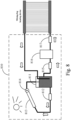
- FIG. 8 is a schematic diagram of a solar heat oil generator of FIG. 7 .
- the solar heat transfer oil generator 810 mainly includes a heat collection plate 813, a heat oil collection barrel 814, and a storage oil barrel 811 and a heat transfer oil boiler 816.
- the flow of the heat transfer oil is promoted by the pumps 812, 815 and 817.
- the pump 815 draws the heat transfer oil from the oil storage barrel 811 and sends it to the heat transfer oil boiler for heating (in this case, when the heating amount in the winter or solar energy is insufficient, the circulating oil can be heated by the heat transfer oil boiler) to a higher temperature.
- the pump 817 will send the heat transfer oil having the higher temperature into the heating pipe for heating the mixing fog.
- the pump 812 will also deliver the heat transfer oil in the oil storage barrel to the heat collection plate 813 and the heat collection oil barrel 814 to maintain the heat transfer oil in the system to a stable higher temperature through the temperature provided by the solar energy in order to decrease the heat energy consumed by the heat transfer oil boiler 816 and shorten a heating time that the heat transfer oil can reach the higher temperature.
Landscapes
- Chemical & Material Sciences (AREA)
- Life Sciences & Earth Sciences (AREA)
- Engineering & Computer Science (AREA)
- Organic Chemistry (AREA)
- Water Supply & Treatment (AREA)
- Environmental & Geological Engineering (AREA)
- Hydrology & Water Resources (AREA)
- Physics & Mathematics (AREA)
- Thermal Sciences (AREA)
- Chemical Kinetics & Catalysis (AREA)
- Sustainable Development (AREA)
- Sustainable Energy (AREA)
- Water Treatment By Electricity Or Magnetism (AREA)
- Heat Treatment Of Water, Waste Water Or Sewage (AREA)
Description
- The present invention relates to a desalination system, specifically to an energy-saving desalination system.
- The vast majority of the water on Earth is in the form of seawater, for about 97% of the earth's surface. However, the seawater is a salt water, which cannot be used as drinking or irrigating water. In other words, the fresh water that naturally exists on the surface of the Earth only accounts for 3%, and most of the fresh water also exists on the surface in the form of glaciers. Therefore, the technology to convert the salt water into usable fresh water has great application requirements.
- The existing techniques for desalination of the salt water are mainly divided into two major categories: an evaporation method and a thin-film method. The basic principle of the evaporation method is to directly vaporize the salt water under reduced pressure so that the salt water can be evaporated under relatively low temperature conditions. A large amount of vapor emerges after the evaporation. After that, humans use different evaporation methods and condensation methods to achieve different speeds and results in condensing fresh water. These methods include multi-effect evaporation, multi-stage flash and vapor compression. But when manufacturing the fresh water by these methods, a lot of energy is consumed to generate steam. The thin-film method mainly includes reverse osmosis method and electrodialysis method. Although the basic principle is to filter the salt water with a semipermeable membrane, the salt ions in the salt water is blocked by the semipermeable membrane, and the water is directly passed through the semipermeable membrane to obtain fresh water. However, since the size of the salt ions is small, the conventional thin film method requires a semi-permeable membrane having a small pore size, which is technically difficult and has high maintenance cost.
US 2016/368784 A1 discloses a desalination system of the evaporation method.IT UA20 164 377 A1 - Accordingly, the way to effectively transform the salt water into a fresh water is required to be solved by the industry.
- The present invention provides an energy-saving desalination system, used for obtaining a salt water from a salt-water source and desalinating to generate a fresh water as defined in
claim 1. - The present invention also provides with another energy-saving desalination system as defined in claim 9.
- In an embodiment of the energy-saving desalination system provided by the present invention, the salt-water preheating device is a portion of the condensing device. Preferably, the condensing device includes a fresh-water extraction device and a salt-water extraction device, and the fresh-water extraction device is simultaneously as the salt-water preheating device.
- In an embodiment of the energy-saving desalination system provided by the present invention, the salt-water reheating device can be a solar water heater, an electric heater, a gas water heater, or a combination thereof.
- The energy-saving desalination system provided by the present invention further includes a re-magnetizing device disposed at a path that the magnetized salt water flows through in order to perform a second magnetization to the magnetized salt water.
- In an embodiment of the energy-saving desalination system provided by the present invention, the he mixing-fog heating device is a solar heat transfer oil generator. The present invention also provides a method for desalinating sea water in claim 17.
- One of the advantages of the above embodiment is that the kinetic energy required for the operation of the overall system is reduced, and using the characteristics of the salt water after being magnetized, directly extracting the salt water (seawater) as a condensing water required extracting the fresh water in the system in order to achieve the energy-saving effect. Cooperating with other green energy, for example, a heating design in a solar energy form so that the power consumption of the overall system is reduced.
-
-
FIG. 1 is a block diagram of an energy-saving desalination system; -
FIG. 2 is a block diagram of a variation of the system of theFIG. 1 ; -
FIG. 3 is a schematic diagram of an energy-saving desalination system according to an embodiment of the present invention; -
FIG. 4 is a flow chart of an energy-saving desalination system according to an embodiment of the present invention; -
FIG. 5 is a block diagram of an energy-saving desalination system; -
FIG. 6 is a block diagram of a variation of the system of theFIG. 5 ; -
FIG. 7 is a schematic diagram of a condensing device according to one embodiment; and -
FIG. 8 is a schematic diagram of a solar heat transfer oil generator ofFIG. 7 . -
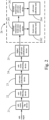
FIG. 1 is a block diagram of an energy-saving desalination system. A salt water (for example, a seawater) is inputted to a salt-water magnetizingdevice 10 to be magnetized, and then being filtered by a salt-water filtering device 11 to filter out impurities in the magnetized salt water. The salt water being magnetized and filtered is heated in a salt-water preheating device 12 to a middle temperature such as 20 degrees to 40 degrees Celsius. Then, the magnetized salt water having the middle temperature enters a salt-water reheating device 13 to be further heated to a magnetized salt water having a higher temperature. A higher temperature salt-water nebulization 14 can be a pneumatic nozzle or an ultrasonic nozzle for nebulizing the magnetized salt water having the higher temperature to become a mixing fog having the higher temperature. A fresh-water extraction device 15 extracts a seawater as a condensation water to condensate the mixing fog having the higher temperature to obtain a fresh water. A remaining portion of the mixing fog enters a concentrated salt-water extraction device 16, and using a depressurized condensation pipe to be cooperated with a demisting mesh to convert the remaining portion of the mixing fog into a concentrated salt water, and the concentrated salt water is also known as a brine. - In this system, the salt-
water filtering device 11 can also adopt a filtering device that is simple and has lower cost. In different application environment, a filtering device that is more precise can be selected according to requirement. -
FIG. 2 is a variation of the system of theFIG. 1 . After the salt water (such as the seawater) is magnetized by a salt-water magnetizingdevice 21, the salt water is filtered by the salt-water filtering device 22 in order to filter out the impurity in the magnetized salt water. The salt water being magnetized and filtered is heated in a salt-water preheating device 23 to a middle temperature such as 20 degrees to 40 degrees Celsius. Then, the salt water having the middle temperature enters a salt-water reheating device 24 to be further heated to a higher temperature. A higher temperature salt-water nebulization device 25 that can be a pneumatic nozzle or an ultrasonic nozzle for nebulizing the magnetized salt water having the middle temperature to become a mixing fog. Then, inputting to acondensing device 26. Thecondensing device 26 includes a fresh-water extraction device 261, a fresh-water collection tank 262, a salt-water extraction device 263 and a concentrated salt-water collection tank 264. The mixing fog is condensed to extract a fresh water by a first pressure and a first temperature in the fresh-water extraction device 261, and stored in the fresh-water collection tank 262. A remaining portion of the mixing fog after being extracted with the fresh water is delivered to the salt-water extraction device 263 to extract a concentrated salt water by a second pressure and a second temperature, and being stored in the concentrated salt-water collection tank 264. The first temperature and the second temperature can be 0 degree to 40 degrees Celsius, and the above temperatures are relative to the temperature of a local seawater introduced by the desalination system. - The salt water after being strongly magnetized can decrease the generation of the incrustant when heating and condensing. In the present system, the salt-
water preheating device 23 can select a solar water heater as a heating device. -
FIG.3 is a schematic diagram of an energy-saving desalination system according to an embodiment of the present invention. In the present embodiment, a salt-water outlet directly connects with a seawater, and the salt-water outlet such as an input terminal of a water pipe is installed with astrong magnet 30 to perform a first magnetization to the salt water passing through, after the salt water being magnetized is filtered out with the impurity by the salt-water filtering device 31, the salt water is stored in a salt-water storage tank 32. Apump 33 is used to extract the salt water stored in the salt-water storage tank 32 and make the salt water to pass throughstrong magnet 34. After performing a second magnetization, delivering to a mixing-fog condensing device 351 of a fresh-water extraction device 35 as a condensation water for condensing a mixing fog after being heated and blowing by anexhaust fan 42. - The salt water after magnetizing twice, at this stage, as a condensation water, the salt water is also heated by a mixing fog after being heated so as to become preheated salt water having a middle temperature. The preheated salt water having the middle temperature is stored in the condensate output pipe (an output pipe of the preheated salt water after being heated) 36, the preheated salt-water
flow control valve 38 controls to provide the water volume required to be nebulized for the system to a salt-water reheating device 39. An excess salt water is discharged into the sea through a salt-water dischargingcontrol valve 37. The salt-water reheating device 39 can be a solar water heater, an electric heater, a gas water heater, or a combination thereof for heating the preheated salt water having the middle temperature to a higher temperature to provide to a highertemperature nebulization device 40. - The higher temperature salt-
water nebulization device 40 can control the salt-water pressurization device 401 and a high pressure air delivered from the airflow control valve 406 that thenozzle 402 cooperates withair compressor 405 such that the salt water having a higher temperature is nebulized as a mixing fog including a salt-water mist component and a fresh-water mist component, and stored the mixing fog in a mixing fog collection tank 404. To maintain the temperature of the mixing fog in a higher temperature range, the present embodiment also provides with ahot air blower 403 to provide an air volume for blowing the mixing fog. Thehot air blower 403 can be a solar hot air blower, an electric hot air blower, or a gas hot air blower. The higher temperature mixing fog is further drawn by theexhaust fan 42 to the fresh-water extraction device 35 through the mixing-fog delivering pipe 41, and using a mixing-fog condensing device 351 to extract out a fresh water with a first temperature and a first pressure, and stored in the fresh-water collection tank 352. An user can use the fresh water through afaucet 353. A remaining portion of the mixing fog having a lower temperature and high concentration salt water is delivered to a concentrated salt-water extraction device 43 to extract a concentrated salt water by a second pressure and a second temperature through a depressurizedcondenser 431, and being stored in the concentrated salt-water collection tank 432. And can be discharged out of the system through a concentrated salt-water outlet 436. The gas portion is discharged out through theexhaust gas outlet 435 by providing power by theexhaust fan 434 and after being filtered with the impurity by thedemisting mesh 433. In the present embodiment, the first temperature is different from the second temperature, and the first pressure is different from the second pressure. -
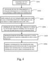
FIG. 4 is a flow chart of an energy-saving desalination system according to an embodiment of the present invention. - Step S501: magnetizing a salt water extracted from the sea;
- Step S502: delivering the salt water after being magnetized to a mixing-fog condensing device as a condensation water, and preheating to a middle temperature simultaneously;
- Step S503: further heating the salt water having the middle temperature using an energy-saving heating method (such as high temperature solar water heater) to a higher temperature (such as 80°C~85°C);
- Step S504: nebulizing the salt water with the higher temperature to a mixing fog with the higher temperature including a salt-water fog and a fresh-water fog using a pressure nozzle or an ultrasonic nozzle;
- Step S505: inputting the mixing fog with the higher temperature to a mixing-fog condensing device to perform a condensation in order to extract a fresh water;
- Step S506: inputting a remaining portion of the mixing fog after being condensed and extracted with the fresh water to a depressurized condenser and a demisting mesh of a concentrated salt-water extraction device in order to collect a concentrated salt water.
-
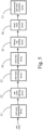
FIG. 5 is a block diagram of another energy-saving desalination system. In this system,, a salt water is inputted to a salt-water magnetizing device 51 to be magnetized, and then being filtered by a salt-water filtering device 52. The salt water is heated in a salt-water preheating device 53 to a middle temperature. Then, the salt water is nebulized to a mixing fog having the middle temperature in a salt-water nebulization device 54 using a mechanism such as an ultrasonic nozzle. Then, using a mixing-fog heating device 55 to heat the mixing fog to a higher temperature and inputting to a fresh-water extraction device 56 in order to condense to obtain a fresh water. The remaining portion of the mixing fog is delivered to the concentrated salt-water extraction device 57 to obtain a concentrated salt water. -
FIG. 6 is a variation of the system of theFIG. 5 . Similarly toFIG. 2 , after the salt water is magnetized by a salt-water magnetizing device 61, the salt water is filtered by the salt-water filtering device 62, heated in a salt-water preheating device 63 to a middle temperature. Then, the salt water is nebulized to a mixing fog having a middle temperature by a salt-water nebulization device 64. Then, heating to a higher temperature through a mixing-fog heating device 65, and inputting to a condensingdevice 66. The condensingdevice 66 includes a fresh-water extraction device 661, a fresh-water collection tank 662, a salt-water extraction device 663 and a concentrated salt-water collection tank 664. The mixing fog with the higher temperature is condensed and extracted to obtain a fresh water under a first pressure and a first temperature by a fresh-water extraction device 661, and stored in the fresh-water collection tank 662. A remaining portion of the mixing fog after being extracted to obtain the fresh water is delivered to a salt-water extraction device 663 to extract and obtain a concentrated salt-water extraction device 663 under a second pressure and a second temperature to obtain a concentrated salt water, and stored in a concentrated salt-water collection tank 664. -
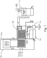
FIG. 7 is a schematic diagram of a condensing device according to one embodiment. With also reference toFIG. 6 , the mixing fog having the middle temperature generated in the salt-water nebulization device 64 is inputted to a mixing-fog heating device 701. The heating energy of the mixing-fog heating device 701 is provided by a solar heattransfer oil generator 7015. The heat transfer oil heats the mixing fog to a required temperature through a heating pipe. The mixing fog after being heated enters to the fresh-water extraction device 708. The condensation water of the fresh-water extraction device 708 is provided by thepump 712 that extracts a salt water (seawater). The fresh water extracted is stored in the fresh-water collection tank 703. The remaining fog is blown to the salt-water extraction device 711 to extract out concentrated salt water and discharge an exhaust gas. -
FIG. 8 is a schematic diagram of a solar heat oil generator ofFIG. 7 . In the present embodiment, the solar heattransfer oil generator 810 mainly includes aheat collection plate 813, a heatoil collection barrel 814, and astorage oil barrel 811 and a heattransfer oil boiler 816. The flow of the heat transfer oil is promoted by thepumps pump 815 draws the heat transfer oil from theoil storage barrel 811 and sends it to the heat transfer oil boiler for heating (in this case, when the heating amount in the winter or solar energy is insufficient, the circulating oil can be heated by the heat transfer oil boiler) to a higher temperature. Thepump 817 will send the heat transfer oil having the higher temperature into the heating pipe for heating the mixing fog. Then, flowing back to theoil storage barrel 811. At the same time, thepump 812 will also deliver the heat transfer oil in the oil storage barrel to theheat collection plate 813 and the heatcollection oil barrel 814 to maintain the heat transfer oil in the system to a stable higher temperature through the temperature provided by the solar energy in order to decrease the heat energy consumed by the heattransfer oil boiler 816 and shorten a heating time that the heat transfer oil can reach the higher temperature. - The above embodiments of the present invention are not used to limit the invention, which is defined by the appended claims.
Claims (17)
- An energy-saving desalination system, used for obtaining a salt water from a salt-water source and desalinating to generate a fresh water, and the system comprising:a salt-water magnetizing device (10, 21, 30) disposed at an intake for magnetizing the salt water to generate a magnetized salt water, wherein the system further includes a re-magnetizing device (34) disposed at a path that the magnetized salt water flows through in order to perform a second magnetization to the magnetized salt water;a salt-water filtering device (11, 22, 31) coupled to the salt-water magnetizing device (10, 21, 30) for filtering the magnetized salt water;a salt-water preheating device (12, 23) coupled to the salt-water filtering device (11, 22, 31) for heating the magnetized salt water such that the magnetized salt water can reach a middle temperature;a salt-water reheating device (13, 24, 39) coupled to the salt-water pre-heating device (12, 23) for heating the magnetized salt water such that the magnetized salt water can maintain in a higher temperature range;a nebulization device (14, 25, 40) coupled to the salt-water reheating device (13, 24, 39) to nebulize the magnetized salt water having a higher temperature into a mixing fog; anda condensing device (26) coupled to the nebulization device (14, 25, 39) to extract a fresh water from the mixing fog;wherein a condensation water required by the condensing device (26) is a salt water extracted from the salt-water source.
- The desalination system according to claim 1, wherein the salt-water preheating device (12, 23) is a portion of the condensing device (26).
- The desalination system according to claim 1, wherein the condensing device (26) includes a fresh-water extraction device (15, 261, 35) and a salt-water extraction device (16, 263, 43), and the fresh-water extraction device (15, 261, 35) is simultaneously as the salt-water preheating device (12, 23).
- The desalination system according to claim 1, wherein the nebulization device (14, 25, 40) includes a pressurization device (401) and a nozzle (402).
- The desalination system according to claim 1, wherein the salt-water reheating device (13, 24, 39) can be a solar water heater, an electric heater, a gas water heater, or a combination thereof.
- The desalination system according to claim 3, wherein the system further includes a salt-water discharging control valve (37) for discharging an excess condensation water out of the system.
- The desalination system according to claim 1, wherein the middle temperature is in a range of 20 degrees to 40 degrees Celsius.
- The desalination system according to claim 1, wherein the higher temperature is in a range of 80 degrees to 85 degrees Celsius.
- An energy-saving desalination system, used for obtaining a salt water from a salt-water source and desalinating to generate a fresh water, and the system comprising:a salt-water magnetizing device (51, 61) disposed at an intake for magnetizing the salt water to generate a magnetized salt water, wherein the system further includes a re-magnetizing device (34) disposed at a path that the magnetized salt water flows through in order to perform a second magnetization to the magnetized salt water;a salt-water filtering device (52, 62) coupled to the salt-water magnetizing device (51, 61) for filtering the magnetized salt water;a salt-water preheating device (53, 63) coupled to the salt-water filtering device (52, 62) for heating the magnetized salt water such that the magnetized salt water can reach a middle temperature;a nebulization device (54, 64) coupled to the salt-water preheating device (53, 63) to nebulize the magnetized salt water into a mixing fog having the middle temperature;a mixing-fog heating device (55, 65, 701) coupled to the nebulization device (54, 64) to heat the mixing fog to a higher temperature; anda condensing device (66) coupled to the mixing-fog heating device (55, 65, 701) to condense the mixing fog to extract out a fresh water;wherein a condensation water required by the condensing device (66) is a salt water extracted from the salt-water source.
- The desalination system according to claim 9, wherein the salt-water preheating device (53, 63) is a portion of the condensing device (66).
- The desalination system according to claim 10, wherein the condensing device (66) includes a fresh-water extraction device (56, 661, 708) and a salt-water extraction device (57, 663, 711), and the fresh-water extraction device (56, 661, 708) is simultaneously as the salt-water preheating device (53, 63).
- The desalination system according to claim 9, wherein the nebulization device (54, 64) includes a pressurization device and a nozzle.
- The desalination system according to claim 9, wherein the system further includes a salt-water discharging control valve for discharging an excess condensation water out of the system.
- The desalination system according to claim 9, wherein the mixing-fog heating device (55, 65, 701) is a solar thermal transfer oil generator (7015, 810).
- The desalination system according to claim 9, wherein the middle temperature is in a range of 20 degrees to 40 degrees Celsius.
- The desalination system according to claim 9, wherein the higher temperature is in a range of 80 degrees to 85 degrees Celsius.
- An energy-saving desalination method for desalinating a seawater to generate a fresh water, and the method comprise steps of:magnetizing a salt water extracted from the sea;performing a second magnetization to the magnetized salt water by a re-magnetizing device (34) disposed at a path that the magnetized salt water flows through;delivering the salt water after being magnetized to a mixing-fog condensing device as a condensing water, and pre-heating to a middle temperature simultaneously;further heating the salt water having the middle temperature using an energy-saving heating method to a higher temperature;nebulizing the salt water with the higher temperature to a mixing fog with the higher temperature;inputting the mixing fog with the higher temperature to a mixing-fog condensing device (66) to perform a condensation in order to extract a fresh water; andinputting a remaining portion of the mixing fog after being condensed and extracted with the fresh water to collect a concentrated salt water.
Applications Claiming Priority (2)
| Application Number | Priority Date | Filing Date | Title |
|---|---|---|---|
| TW107112319 | 2018-04-10 | ||
| TW107137581A TWI711585B (en) | 2018-04-10 | 2018-10-24 | Energy-saving salt water desalination system |
Publications (3)
| Publication Number | Publication Date |
|---|---|
| EP3553031A1 EP3553031A1 (en) | 2019-10-16 |
| EP3553031C0 EP3553031C0 (en) | 2023-09-13 |
| EP3553031B1 true EP3553031B1 (en) | 2023-09-13 |
Family
ID=66290183
Family Applications (1)
| Application Number | Title | Priority Date | Filing Date |
|---|---|---|---|
| EP19168442.2A Active EP3553031B1 (en) | 2018-04-10 | 2019-04-10 | Energy saving desalination system |
Country Status (4)
| Country | Link |
|---|---|
| US (1) | US11014833B2 (en) |
| EP (1) | EP3553031B1 (en) |
| CN (1) | CN110357343A (en) |
| ES (1) | ES2965154T3 (en) |
Families Citing this family (9)
| Publication number | Priority date | Publication date | Assignee | Title |
|---|---|---|---|---|
| TW201943656A (en) * | 2018-04-10 | 2019-11-16 | 金杰科技股份有限公司 | Water purification system, water dispenser and washing basin applying the same |
| US12162780B2 (en) * | 2019-12-09 | 2024-12-10 | Blue Mountain International, LLC | Desalination systems and methods |
| CN113428922B (en) * | 2021-06-07 | 2022-11-11 | 淮南联合大学 | Based on solar energy transduction atomizing sea water desalination device |
| US11502322B1 (en) | 2022-05-09 | 2022-11-15 | Rahul S Nana | Reverse electrodialysis cell with heat pump |
| US11502323B1 (en) | 2022-05-09 | 2022-11-15 | Rahul S Nana | Reverse electrodialysis cell and methods of use thereof |
| US12040517B2 (en) | 2022-11-15 | 2024-07-16 | Rahul S. Nana | Reverse electrodialysis or pressure-retarded osmosis cell and methods of use thereof |
| US11855324B1 (en) | 2022-11-15 | 2023-12-26 | Rahul S. Nana | Reverse electrodialysis or pressure-retarded osmosis cell with heat pump |
| JP2025538227A (en) | 2022-11-15 | 2025-11-26 | エス ナナ,ラフル | Reverse electrodialysis or pressure retarded osmosis cell and method of use thereof |
| CN119929949B (en) * | 2024-12-27 | 2025-12-12 | 常州大学 | Brackish lake water purification device |
Citations (1)
| Publication number | Priority date | Publication date | Assignee | Title |
|---|---|---|---|---|
| ITUA20164377A1 (en) * | 2016-06-15 | 2017-12-15 | I F T International Filtration Tech S R L Via Felice Pusterla 29 22070 Grandate Como | DEVICE AND PROCESS OF PURIFICATION OF WATER BY MEANS OF NANO AND ULTRAFILTRATION |
Family Cites Families (23)
| Publication number | Priority date | Publication date | Assignee | Title |
|---|---|---|---|---|
| CH664550A5 (en) * | 1986-04-04 | 1988-03-15 | Esi S A | Demineralising water with reverse osmosis membrane - by passing it through magnetic container before filtration |
| CN2104862U (en) * | 1991-10-27 | 1992-05-20 | 王友军 | Salt water desalter |
| CN2139935Y (en) * | 1992-12-29 | 1993-08-11 | 苏振芳 | Magnetic water apparatus for kettle |
| CN2230755Y (en) * | 1993-04-07 | 1996-07-10 | 邝德明 | Seawater desalter |
| CN1730404A (en) * | 2004-08-06 | 2006-02-08 | 汪双清 | Electro-magnetism sea water desalination method and apparatus thereof |
| KR100659375B1 (en) * | 2005-08-30 | 2006-12-19 | (주)동양화학 | Seawater desalination apparatus using atomized steam |
| US9771278B2 (en) * | 2010-10-11 | 2017-09-26 | H2O Global Llc | High efficiency, large scale desalination system |
| CN102336448B (en) * | 2011-08-29 | 2013-03-27 | 陶欣 | Saline treatment system and method |
| CN102344179A (en) * | 2011-09-29 | 2012-02-08 | 中国科学院广州能源研究所 | Solar absorption type sea water desalination device with regenerative cycle |
| CN102432132A (en) * | 2011-11-11 | 2012-05-02 | 沈阳创达技术交易市场有限公司 | Seawater desalting method |
| CN202465444U (en) * | 2012-02-24 | 2012-10-03 | 珠海格力电器股份有限公司 | Seawater desalination device |
| CN103232086A (en) * | 2013-05-20 | 2013-08-07 | 上海电力学院 | Solar seawater desalting system |
| CN103723875B (en) * | 2013-12-31 | 2015-03-25 | 朱江 | Seawater full recycling process |
| CN204939177U (en) * | 2015-09-11 | 2016-01-06 | 内蒙古大学 | A kind of efficient magnetic force water softening device |
| CN105439232B (en) * | 2015-12-14 | 2018-03-02 | 西安交通大学 | A kind of heat pump type sea water desalination device and its control method with step preheating |
| US9701551B2 (en) * | 2015-12-15 | 2017-07-11 | King Fahd University Of Petroleum And Minerals | Hydromagnetic desalination cell, brine desalination system, and method of desalinating brine water using the desalination cell |
| CN205527829U (en) * | 2016-03-03 | 2016-08-31 | 国家海洋局天津海水淡化与综合利用研究所 | Formula of condensing outward slope core pattern solar energy distillation sea water desalination device |
| CN105565412B (en) * | 2016-03-03 | 2017-12-15 | 国家海洋局天津海水淡化与综合利用研究所 | A kind of outer coagulating type tilts core pattern solar distilling seawater desalinating device |
| CN105836948B (en) * | 2016-03-31 | 2019-04-09 | 红门智能科技股份有限公司 | The method and system of fresh water are prepared using the seawater and freshwater moisture condensation temperature difference |
| CN106241926B (en) * | 2016-09-07 | 2019-04-12 | 西安建筑科技大学 | A kind of solar energy double-stage heating desalination plant |
| CN207002313U (en) * | 2016-09-27 | 2018-02-13 | 杨可 | A kind of negative pressure ultrasound atomization type solar energy sea water desalination apparatus |
| CN206767688U (en) * | 2017-03-15 | 2017-12-19 | 江苏德邦工程有限公司 | New and effective portable full solar energy sea water desalination apparatus |
| CN107416933A (en) * | 2017-05-25 | 2017-12-01 | 白惠中 | Solar energy sea water desalination apparatus and method |
-
2019
- 2019-04-09 US US16/379,495 patent/US11014833B2/en active Active
- 2019-04-10 CN CN201910283621.8A patent/CN110357343A/en active Pending
- 2019-04-10 EP EP19168442.2A patent/EP3553031B1/en active Active
- 2019-04-10 ES ES19168442T patent/ES2965154T3/en active Active
Patent Citations (1)
| Publication number | Priority date | Publication date | Assignee | Title |
|---|---|---|---|---|
| ITUA20164377A1 (en) * | 2016-06-15 | 2017-12-15 | I F T International Filtration Tech S R L Via Felice Pusterla 29 22070 Grandate Como | DEVICE AND PROCESS OF PURIFICATION OF WATER BY MEANS OF NANO AND ULTRAFILTRATION |
Also Published As
| Publication number | Publication date |
|---|---|
| CN110357343A (en) | 2019-10-22 |
| US20190308889A1 (en) | 2019-10-10 |
| ES2965154T3 (en) | 2024-04-11 |
| US11014833B2 (en) | 2021-05-25 |
| EP3553031C0 (en) | 2023-09-13 |
| EP3553031A1 (en) | 2019-10-16 |
Similar Documents
| Publication | Publication Date | Title |
|---|---|---|
| EP3553031B1 (en) | Energy saving desalination system | |
| CN100497190C (en) | Low-position heat energy spray evaporation-multiple-effect distillation seawater desalination method and device | |
| CN205307834U (en) | Absorption heat pump sea water desalination device of recovery waste heat | |
| KR101632252B1 (en) | Pure liquid production device | |
| CN205170431U (en) | Solar energy absorption heat pump sea water desalination device | |
| CN104609488A (en) | Cascade seawater desalination system and method thereof | |
| CN104803532B (en) | A kind of membrane type humidifies dehumidification sea water desalinating unit and method for desalting seawater | |
| CN104355471A (en) | Novel thermal membrane coupling seawater desalinating system and process | |
| JP2012239956A (en) | Desalination apparatus and method for producing fresh water | |
| ES2302224T3 (en) | DESALINATION PROCESS BY DISTILLATION MSF AND APPLIANCE. | |
| US9790103B2 (en) | Hydrogen-powered desalination plant | |
| CN202849193U (en) | Multistage vacuum distillation seawater desalting device | |
| CN205035108U (en) | A light water condenser for sea water desalination device | |
| CN108408812A (en) | A kind of desalting method and device of brine waste | |
| CN106698564A (en) | Sea water desalinization method by waste heat recovery | |
| EP4405304B1 (en) | Low energy ejector desalination system | |
| TWI711585B (en) | Energy-saving salt water desalination system | |
| Darwish | Thermal desalination in GCC and possible development | |
| CN101134605A (en) | Temperature-differential sea-water distillator | |
| CN207435085U (en) | Minimize positive pressure distillation seawater desalination system | |
| CN202880943U (en) | Solar sea water desalinization device based on centrifugal atomization technology | |
| CN103539215A (en) | Sewage treatment system and process | |
| KR101587123B1 (en) | Freshwater Apparatus of Seawater of MED and VMD Hybrid Type using Ejector | |
| CN104925885A (en) | Electromagnetic desalination device | |
| KR101642842B1 (en) | System for seawater concentrating and scale crystallizing |
Legal Events
| Date | Code | Title | Description |
|---|---|---|---|
| PUAI | Public reference made under article 153(3) epc to a published international application that has entered the european phase |
Free format text: ORIGINAL CODE: 0009012 |
|
| STAA | Information on the status of an ep patent application or granted ep patent |
Free format text: STATUS: THE APPLICATION HAS BEEN PUBLISHED |
|
| AK | Designated contracting states |
Kind code of ref document: A1 Designated state(s): AL AT BE BG CH CY CZ DE DK EE ES FI FR GB GR HR HU IE IS IT LI LT LU LV MC MK MT NL NO PL PT RO RS SE SI SK SM TR |
|
| AX | Request for extension of the european patent |
Extension state: BA ME |
|
| STAA | Information on the status of an ep patent application or granted ep patent |
Free format text: STATUS: REQUEST FOR EXAMINATION WAS MADE |
|
| 17P | Request for examination filed |
Effective date: 20200313 |
|
| RBV | Designated contracting states (corrected) |
Designated state(s): AL AT BE BG CH CY CZ DE DK EE ES FI FR GB GR HR HU IE IS IT LI LT LU LV MC MK MT NL NO PL PT RO RS SE SI SK SM TR |
|
| STAA | Information on the status of an ep patent application or granted ep patent |
Free format text: STATUS: EXAMINATION IS IN PROGRESS |
|
| 17Q | First examination report despatched |
Effective date: 20210322 |
|
| GRAP | Despatch of communication of intention to grant a patent |
Free format text: ORIGINAL CODE: EPIDOSNIGR1 |
|
| STAA | Information on the status of an ep patent application or granted ep patent |
Free format text: STATUS: GRANT OF PATENT IS INTENDED |
|
| RIC1 | Information provided on ipc code assigned before grant |
Ipc: B01D 5/00 20060101ALN20230417BHEP Ipc: B01D 1/00 20060101ALN20230417BHEP Ipc: C02F 103/08 20060101ALN20230417BHEP Ipc: C02F 1/14 20060101ALN20230417BHEP Ipc: C02F 1/00 20060101ALN20230417BHEP Ipc: B01D 1/28 20060101ALI20230417BHEP Ipc: C02F 1/12 20060101ALI20230417BHEP Ipc: C02F 1/48 20060101ALI20230417BHEP Ipc: C02F 1/04 20060101AFI20230417BHEP |
|
| INTG | Intention to grant announced |
Effective date: 20230510 |
|
| GRAS | Grant fee paid |
Free format text: ORIGINAL CODE: EPIDOSNIGR3 |
|
| GRAA | (expected) grant |
Free format text: ORIGINAL CODE: 0009210 |
|
| STAA | Information on the status of an ep patent application or granted ep patent |
Free format text: STATUS: THE PATENT HAS BEEN GRANTED |
|
| AK | Designated contracting states |
Kind code of ref document: B1 Designated state(s): AL AT BE BG CH CY CZ DE DK EE ES FI FR GB GR HR HU IE IS IT LI LT LU LV MC MK MT NL NO PL PT RO RS SE SI SK SM TR |
|
| REG | Reference to a national code |
Ref country code: CH Ref legal event code: EP |
|
| REG | Reference to a national code |
Ref country code: DE Ref legal event code: R096 Ref document number: 602019037204 Country of ref document: DE |
|
| REG | Reference to a national code |
Ref country code: IE Ref legal event code: FG4D |
|
| U01 | Request for unitary effect filed |
Effective date: 20231012 |
|
| U07 | Unitary effect registered |
Designated state(s): AT BE BG DE DK EE FI FR IT LT LU LV MT NL PT SE SI Effective date: 20231018 |
|
| PG25 | Lapsed in a contracting state [announced via postgrant information from national office to epo] |
Ref country code: GR Free format text: LAPSE BECAUSE OF FAILURE TO SUBMIT A TRANSLATION OF THE DESCRIPTION OR TO PAY THE FEE WITHIN THE PRESCRIBED TIME-LIMIT Effective date: 20231214 |
|
| PG25 | Lapsed in a contracting state [announced via postgrant information from national office to epo] |
Ref country code: RS Free format text: LAPSE BECAUSE OF FAILURE TO SUBMIT A TRANSLATION OF THE DESCRIPTION OR TO PAY THE FEE WITHIN THE PRESCRIBED TIME-LIMIT Effective date: 20230913 Ref country code: NO Free format text: LAPSE BECAUSE OF FAILURE TO SUBMIT A TRANSLATION OF THE DESCRIPTION OR TO PAY THE FEE WITHIN THE PRESCRIBED TIME-LIMIT Effective date: 20231213 Ref country code: HR Free format text: LAPSE BECAUSE OF FAILURE TO SUBMIT A TRANSLATION OF THE DESCRIPTION OR TO PAY THE FEE WITHIN THE PRESCRIBED TIME-LIMIT Effective date: 20230913 Ref country code: GR Free format text: LAPSE BECAUSE OF FAILURE TO SUBMIT A TRANSLATION OF THE DESCRIPTION OR TO PAY THE FEE WITHIN THE PRESCRIBED TIME-LIMIT Effective date: 20231214 |
|
| PG25 | Lapsed in a contracting state [announced via postgrant information from national office to epo] |
Ref country code: IS Free format text: LAPSE BECAUSE OF FAILURE TO SUBMIT A TRANSLATION OF THE DESCRIPTION OR TO PAY THE FEE WITHIN THE PRESCRIBED TIME-LIMIT Effective date: 20240113 |
|
| REG | Reference to a national code |
Ref country code: ES Ref legal event code: FG2A Ref document number: 2965154 Country of ref document: ES Kind code of ref document: T3 Effective date: 20240411 |
|
| PG25 | Lapsed in a contracting state [announced via postgrant information from national office to epo] |
Ref country code: SM Free format text: LAPSE BECAUSE OF FAILURE TO SUBMIT A TRANSLATION OF THE DESCRIPTION OR TO PAY THE FEE WITHIN THE PRESCRIBED TIME-LIMIT Effective date: 20230913 Ref country code: RO Free format text: LAPSE BECAUSE OF FAILURE TO SUBMIT A TRANSLATION OF THE DESCRIPTION OR TO PAY THE FEE WITHIN THE PRESCRIBED TIME-LIMIT Effective date: 20230913 Ref country code: IS Free format text: LAPSE BECAUSE OF FAILURE TO SUBMIT A TRANSLATION OF THE DESCRIPTION OR TO PAY THE FEE WITHIN THE PRESCRIBED TIME-LIMIT Effective date: 20240113 Ref country code: CZ Free format text: LAPSE BECAUSE OF FAILURE TO SUBMIT A TRANSLATION OF THE DESCRIPTION OR TO PAY THE FEE WITHIN THE PRESCRIBED TIME-LIMIT Effective date: 20230913 Ref country code: SK Free format text: LAPSE BECAUSE OF FAILURE TO SUBMIT A TRANSLATION OF THE DESCRIPTION OR TO PAY THE FEE WITHIN THE PRESCRIBED TIME-LIMIT Effective date: 20230913 |
|
| PG25 | Lapsed in a contracting state [announced via postgrant information from national office to epo] |
Ref country code: PL Free format text: LAPSE BECAUSE OF FAILURE TO SUBMIT A TRANSLATION OF THE DESCRIPTION OR TO PAY THE FEE WITHIN THE PRESCRIBED TIME-LIMIT Effective date: 20230913 |
|
| REG | Reference to a national code |
Ref country code: DE Ref legal event code: R097 Ref document number: 602019037204 Country of ref document: DE |
|
| PLBE | No opposition filed within time limit |
Free format text: ORIGINAL CODE: 0009261 |
|
| STAA | Information on the status of an ep patent application or granted ep patent |
Free format text: STATUS: NO OPPOSITION FILED WITHIN TIME LIMIT |
|
| 26N | No opposition filed |
Effective date: 20240614 |
|
| U21 | Renewal fee for the european patent with unitary effect paid with additional fee |
Year of fee payment: 6 Effective date: 20240918 |
|
| PG25 | Lapsed in a contracting state [announced via postgrant information from national office to epo] |
Ref country code: MC Free format text: LAPSE BECAUSE OF FAILURE TO SUBMIT A TRANSLATION OF THE DESCRIPTION OR TO PAY THE FEE WITHIN THE PRESCRIBED TIME-LIMIT Effective date: 20230913 |
|
| PG25 | Lapsed in a contracting state [announced via postgrant information from national office to epo] |
Ref country code: MC Free format text: LAPSE BECAUSE OF FAILURE TO SUBMIT A TRANSLATION OF THE DESCRIPTION OR TO PAY THE FEE WITHIN THE PRESCRIBED TIME-LIMIT Effective date: 20230913 |
|
| REG | Reference to a national code |
Ref country code: CH Ref legal event code: PL |
|
| GBPC | Gb: european patent ceased through non-payment of renewal fee |
Effective date: 20240410 |
|
| PG25 | Lapsed in a contracting state [announced via postgrant information from national office to epo] |
Ref country code: GB Free format text: LAPSE BECAUSE OF NON-PAYMENT OF DUE FEES Effective date: 20240410 |
|
| PG25 | Lapsed in a contracting state [announced via postgrant information from national office to epo] |
Ref country code: GB Free format text: LAPSE BECAUSE OF NON-PAYMENT OF DUE FEES Effective date: 20240410 Ref country code: CH Free format text: LAPSE BECAUSE OF NON-PAYMENT OF DUE FEES Effective date: 20240430 |
|
| PG25 | Lapsed in a contracting state [announced via postgrant information from national office to epo] |
Ref country code: IE Free format text: LAPSE BECAUSE OF NON-PAYMENT OF DUE FEES Effective date: 20240410 |
|
| U20 | Renewal fee for the european patent with unitary effect paid |
Year of fee payment: 7 Effective date: 20250417 |
|
| PGFP | Annual fee paid to national office [announced via postgrant information from national office to epo] |
Ref country code: ES Payment date: 20250530 Year of fee payment: 7 |
|
| PG25 | Lapsed in a contracting state [announced via postgrant information from national office to epo] |
Ref country code: CY Free format text: LAPSE BECAUSE OF FAILURE TO SUBMIT A TRANSLATION OF THE DESCRIPTION OR TO PAY THE FEE WITHIN THE PRESCRIBED TIME-LIMIT; INVALID AB INITIO Effective date: 20190410 |
|
| PG25 | Lapsed in a contracting state [announced via postgrant information from national office to epo] |
Ref country code: HU Free format text: LAPSE BECAUSE OF FAILURE TO SUBMIT A TRANSLATION OF THE DESCRIPTION OR TO PAY THE FEE WITHIN THE PRESCRIBED TIME-LIMIT; INVALID AB INITIO Effective date: 20190410 |