EP3552974A1 - Doppelmodus-flugzeuglichtanordnung - Google Patents
Doppelmodus-flugzeuglichtanordnung Download PDFInfo
- Publication number
- EP3552974A1 EP3552974A1 EP19177332.4A EP19177332A EP3552974A1 EP 3552974 A1 EP3552974 A1 EP 3552974A1 EP 19177332 A EP19177332 A EP 19177332A EP 3552974 A1 EP3552974 A1 EP 3552974A1
- Authority
- EP
- European Patent Office
- Prior art keywords
- light
- covert
- aircraft
- various embodiments
- dual mode
- Prior art date
- Legal status (The legal status is an assumption and is not a legal conclusion. Google has not performed a legal analysis and makes no representation as to the accuracy of the status listed.)
- Granted
Links
Images

Classifications
-
- B—PERFORMING OPERATIONS; TRANSPORTING
- B64—AIRCRAFT; AVIATION; COSMONAUTICS
- B64D—EQUIPMENT FOR FITTING IN OR TO AIRCRAFT; FLIGHT SUITS; PARACHUTES; ARRANGEMENT OR MOUNTING OF POWER PLANTS OR PROPULSION TRANSMISSIONS IN AIRCRAFT
- B64D47/00—Equipment not otherwise provided for
- B64D47/02—Arrangements or adaptations of signal or lighting devices
- B64D47/06—Arrangements or adaptations of signal or lighting devices for indicating aircraft presence
-
- B—PERFORMING OPERATIONS; TRANSPORTING
- B64—AIRCRAFT; AVIATION; COSMONAUTICS
- B64D—EQUIPMENT FOR FITTING IN OR TO AIRCRAFT; FLIGHT SUITS; PARACHUTES; ARRANGEMENT OR MOUNTING OF POWER PLANTS OR PROPULSION TRANSMISSIONS IN AIRCRAFT
- B64D47/00—Equipment not otherwise provided for
- B64D47/02—Arrangements or adaptations of signal or lighting devices
- B64D47/04—Arrangements or adaptations of signal or lighting devices the lighting devices being primarily intended to illuminate the way ahead
-
- F—MECHANICAL ENGINEERING; LIGHTING; HEATING; WEAPONS; BLASTING
- F21—LIGHTING
- F21V—FUNCTIONAL FEATURES OR DETAILS OF LIGHTING DEVICES OR SYSTEMS THEREOF; STRUCTURAL COMBINATIONS OF LIGHTING DEVICES WITH OTHER ARTICLES, NOT OTHERWISE PROVIDED FOR
- F21V11/00—Screens not covered by groups F21V1/00, F21V3/00, F21V7/00 or F21V9/00
- F21V11/16—Screens not covered by groups F21V1/00, F21V3/00, F21V7/00 or F21V9/00 using sheets without apertures, e.g. fixed
-
- F—MECHANICAL ENGINEERING; LIGHTING; HEATING; WEAPONS; BLASTING
- F21—LIGHTING
- F21V—FUNCTIONAL FEATURES OR DETAILS OF LIGHTING DEVICES OR SYSTEMS THEREOF; STRUCTURAL COMBINATIONS OF LIGHTING DEVICES WITH OTHER ARTICLES, NOT OTHERWISE PROVIDED FOR
- F21V7/00—Reflectors for light sources
-
- B—PERFORMING OPERATIONS; TRANSPORTING
- B64—AIRCRAFT; AVIATION; COSMONAUTICS
- B64D—EQUIPMENT FOR FITTING IN OR TO AIRCRAFT; FLIGHT SUITS; PARACHUTES; ARRANGEMENT OR MOUNTING OF POWER PLANTS OR PROPULSION TRANSMISSIONS IN AIRCRAFT
- B64D2203/00—Aircraft or airfield lights using LEDs
-
- F—MECHANICAL ENGINEERING; LIGHTING; HEATING; WEAPONS; BLASTING
- F21—LIGHTING
- F21W—INDEXING SCHEME ASSOCIATED WITH SUBCLASSES F21K, F21L, F21S and F21V, RELATING TO USES OR APPLICATIONS OF LIGHTING DEVICES OR SYSTEMS
- F21W2107/00—Use or application of lighting devices on or in particular types of vehicles
- F21W2107/30—Use or application of lighting devices on or in particular types of vehicles for aircraft
-
- F—MECHANICAL ENGINEERING; LIGHTING; HEATING; WEAPONS; BLASTING
- F21—LIGHTING
- F21Y—INDEXING SCHEME ASSOCIATED WITH SUBCLASSES F21K, F21L, F21S and F21V, RELATING TO THE FORM OR THE KIND OF THE LIGHT SOURCES OR OF THE COLOUR OF THE LIGHT EMITTED
- F21Y2115/00—Light-generating elements of semiconductor light sources
- F21Y2115/10—Light-emitting diodes [LED]
Definitions
- the present disclosure relates to aircraft position lights, and more specifically, to dual mode aircraft light assemblies.
- Aircraft position lights are regulated by the Federal Aviation Administration ("FAA”) and other regulatory agencies. Position lights improve the visibility of aircraft, thereby allowing air traffic controllers and other aircraft to visually identify and orient the aircraft.
- non-visible lights such as infrared lights
- Such non-visible lights enable an aircraft to operate in covert mode. In covert mode, bystanders using the naked eye are unable to see the non-visible lights but people equipped with appropriate devices, such as infrared detectors, are able to perceive the non-visible light and thereby identify and orient the aircraft.
- the present disclosure provides a dual mode light assembly for a position light of an aircraft.
- the dual mode light assembly includes a base, a visible light source mounted to the base that is configured to emit visible light, a covert light source mounted to the base that is configured to emit covert light, and at least one light shield mounted to the base.
- the at least one light shield is configured to restrict transmission of the visible light to a visible light pattern and to restrict transmission of the covert light to a covert light pattern.
- the position light is a forward position light and the at least one light shield is a single light shield that is laterally offset relative to the visible light source on the base to block inboard transmission of the visible light.
- the visible light pattern may be bounded by a blocking element of at least one of the dual mode light assembly and the aircraft such that a horizontal angle of the visible light pattern between the single light shield and the blocking element is at least 110 degrees but less than 120 degrees.
- the blocking element may include a blocking surface of the base.
- the base may be angled in an aft direction.
- the single light shield is disposed below the covert light source on the base to block downward transmission of the covert light. Accordingly, a vertical angle of the covert light pattern between a horizontal plane and the single light shield may be at most 45 degrees downwards.
- the dual mode light assembly further includes a reflector mounted to the base that is configured to reflect the covert light in an aft direction such that a horizontal angle of the covert light pattern from a line of flight of the aircraft is at least 120 degrees. The reflector may be laterally offset relative to the covert light source on the base to block inboard transmission of the covert light.
- the visible light source may include a light emitting diode. In various embodiments, the visible light source includes multiple light emitting diodes vertically aligned across the base. In various embodiments, the covert light source includes an infrared emitter. In various embodiments, the visible light source is both vertically and horizontally offset from the covert light source. In various embodiments, the visible light source is laterally offset relative to the covert light source.
- the single light shield may be an arch structure that extends outward and across the base. Components of the base may be mounted to the base under a span of the arch. In various embodiments, the single light shield may be separate from a housing of the dual mode light assembly.
- the dual mode light assembly includes a base, a visible light source, a covert light source, a single light shield, and a reflector.
- the visible light source may be mounted to the base and may be configured to emit visible light.
- the covert light source may be mounted to the base and may be configured to emit covert light.
- the single light shield may be mounted to the base and may be configured to restrict transmission of the visible light to a visible light pattern and to restrict transmission of the covert light to a covert light pattern.
- the single light shield may be laterally offset relative to the visible light source on the base to block inboard transmission of the visible light.
- the visible light pattern may be bounded by a blocking element of at least one of the dual mode light assembly and the aircraft.
- a horizontal angle of the visible light pattern between the single light shield and the blocking element may be at least 110 degrees but less than 120 degrees.
- the single light shield may be disposed below the covert light source on the base to block downward transmission of the covert light, thus a vertical angle of the covert light pattern between a horizontal plane and the single light shield may be at most 45 degrees downwards.
- the reflector may be mounted to the base and may be configured to reflect the covert light in an aft direction such that a horizontal angle of the covert light pattern from a line of flight of the aircraft is at least 120 degrees.
- a dual mode light assembly for an aft position light of an aircraft.
- the dual mode light assembly includes a base, a visible light source mounted to the base that is configured to emit visible light, a covert light source mounted to the base that is configured to emit covert light, a first light shield configured to limit restrict transmission of the visible light to a visible light pattern, and a second light shield mounted to the base and configured to restrict transmission of the covert light to a covert light pattern.
- a horizontal angle of the visible light pattern is 120 degrees and a vertical angle of the covert light pattern between a horizontal plane and the second light shield is at most 45 degrees downwards.
- an aircraft having a forward dual mode light assembly disposed on each side of the aircraft and an aft dual mode light assembly disposed on an aft section of the aircraft.
- Each of the forward dual mode light assemblies may have a first visible light source and a first covert light source mounted to a first single base.
- the aft dual mode light assembly may include a second visible light source and a second covert light source mounted to a second single base.
- the first light shield may extend in an aft direction from peripheral edges of an aft facing surface of the base.
- the visible light source may include multiple light emitting diodes disposed around the covert light source.
- a dual mode light assembly is disclosed herein.
- the dual mode light assembly includes both a visible light source and a covert light source mounted to the same base. Stated differently, the dual mode light assembly disclosed herein enables an aircraft to operate in two modes, either visible mode or covert mode, without having two separate assemblies/modules for each different type of light.
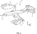
- an aircraft 10 generally includes forward facing position lights 21, 22 disposed on each side of the aircraft 10.
- the forward facing position lights 21, 22 are disposed as far apart laterally as practicable on the aircraft 10.
- the aircraft 10 generally also includes an aft facing position light 23.
- the right forward position light 21 emits green visible light 31
- the left forward position light 22 emits red visible light 32
- the aft position light 23 emits white light 33.
- conventional aircraft 10 generally include separate position light assemblies disposed proximate or adjacent to the visible lights 21, 22, 23.
- XYZ axes are shown in the figures for convenience, with z extending perpendicular to the xy plane.
- a measurement point displaced in the positive z axis direction from a given reference point may be considered “above” or on "top” of the given reference point.
- a measurement point displaced in the negative z axis direction from the given reference point may be considered “below” or on “bottom” of the given reference point.
- the terms “top” and “bottom” may refer to relative positions along the z axis.
- FIG. 1 Also shown in FIG. 1 is an indication of a line of flight 11 of the aircraft 10.
- the XYZ axes, as well as the terms “horizontal” and “vertical”, are associated with and relative to the line of flight 11.
- a horizontal plane is a plane that is parallel to the line of flight 11 and not necessarily parallel to ground.
- horizontal angles are angles are in the xy plane, which is relative to the line of flight 11
- vertical angles are angles in the yz plane, which is relative to the line of flight 11.
- the terms “inboard” and “outboard” are position terms relative to the fuselage of the aircraft 10. Said differently, if a first component is inboard relative to a second component, the first component is nearer the fuselage than the second component.
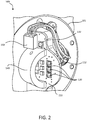
- FIG. 2 shows a perspective view of a dual mode light assembly 100 for a forward position light of the aircraft 10.
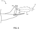
- a dual mode light assembly 200 for an aft position light is described in detail below with reference to FIG. 5 .
- the dual mode light assembly 100 includes a base 110, one or more visible light sources 120, one or more covert light sources 130, a light shield 140, and a reflector 150.
- both the visible light source 120 and the covert light source 130 may be mounted, according to various embodiments, to the same base 110.
- the base 110 may be a wiring board, a circuit board, a wiring substrate, a circuit substrate, a printed wiring assembly, a printed circuit assembly, or a printed circuit board, among others.
- the base 110 may have circuity components and other features attached thereto.
- the visible light source 120 is configured to emit a visible light.
- the visible light source 120 may be a light emitting diode or another device or article that produces visible light, such as electromagnetic radiation having a wavelength of about 400nm to less than 700nm.
- the visible light source 120 may have a specific color (e.g., wavelength) based on which side of the aircraft 10 the dual mode light assembly 100 is positioned.
- the covert light source 130 is configured to emit a covert light.
- the term "covert light” refers to electromagnetic radiation that is not visible to the naked human eye.
- the covert light source 130 may be an infrared emitter that emits infrared radiation, such as radiation having a wavelength of about 700nm to 1000nm.
- the dual mode light assembly 100 is configured to comply with visible light standards and covert light standards.
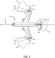
- the light shield 140 is shown mounted to the base and is configured to restrict transmission of both the visible light and the covert light. Said differently, the light shield 140 blocks at least portions of the visible light to form a visible light pattern 122 ( FIG. 3 ) and at least portions of the covert light to form a covert light pattern 132 ( FIG. 3 and 4 ).
- the dual mode light assembly 100 may also include a reflector 150 that is configured to further contribute to the light patterns 122, 132.
- the one or more visible light sources 120 are disposed outboard relative to the light shield 140.
- the light shield 140 may be made from a material that blocks light and thus does not allow light to transmit through itself. In such a configuration, transmission of visible light is blocked from being directed inboard towards the fuselage of the aircraft by the light shield 140. Such a feature may be beneficial, according to various embodiments, to prevent the visible light from distracting the pilot and/or passengers of the aircraft 10.
- the dual mode light assembly 100 may also include a blocking element, such as a blocking surface 112 of the base 110, that may provide an opposite boundary for the visible light pattern 122. As described in greater detail below, the blocking surface 112 may also provide a boundary for the covert light pattern 132.
- inboard transmission of visible light may be restricted by the light shield 140 and outboard transmission of visible light may be restricted by the blocking surface 112 of the base 110, according to various embodiments.
- the visible light pattern 122 may have a horizontal angle 124 that is restricted between the light shield 140 on one side and the blocking surface 112 of the base 110 on the other.
- the horizontal angle 124 of the visible light pattern 122 may be at least about 110 degrees but less than about 120 degrees, wherein the term about in this context only means +/- 2 degrees.
- certain regulations may suggest or require that visible light should be transmitted up to 110 degrees from a vertical plane parallel to the line of flight 11. However, such regulations may also suggest or require that the visible light not be transmitted beyond 120 degrees from the vertical plane parallel to the line of flight 11.
- the base 110 may be angled in an aft direction. As shown in FIG. 2 , the blocking surface 112 is angled towards the aft of the aircraft 10, thus enabling the visible light pattern to extend, for example, the entire 110 degrees from the line of flight 11 of the aircraft 10. In various embodiments, the base may be disposed at an angle to the vertical plane that contains the line of flight.
- light shield 140 may be disposed below the covert light source 130 in order to block downward transmission of the covert light.
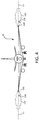
- a vertical angle 136 of the covert light pattern 132 ( FIG. 4 ) between a horizontal plane 12 and the light shield 140 is at most about 45 degrees downwards, wherein the term about in this context only means +/- 2 degrees.
- the reflector 150 may be mounted to the base 110 in various embodiments and may be configured to reflect the covert light in an aft direction such that a horizontal angle 134 of the covert light pattern 132 from the line of flight 11 of the aircraft 10 is at least 120 degrees. Said differently, the covert light pattern 132 may extend, whether suggested by regulation or not, up to and beyond 120 degrees (the horizontal angle 134 shown in FIG. 3 ), as measured from a vertical yz plane parallel to the line of flight 11 of the aircraft 10. In various embodiments, the reflector 150 may be laterally offset (e.g., inboard) relative to the covert light source 130 to block inboard transmission of the covert light, similar to the inboard transmission blocking of the light shield 140 for the visible light.
- laterally offset e.g., inboard
- the visible light source 120 may include multiple light emitting diodes.
- the multiple light emitting diodes may be aligned vertically, for example, across the surface of the base 110.
- the relative positioning of the visible light source 120 and the covert light source 130 may be offset.
- the offset may be both horizontal and vertical.
- the visible light source 120 may be disposed outboard relative to the covert light source 130.
- the light shield 140 may have a shape that is specific to a given configuration.
- the light shield 140 may have an arch structure that extends outward away from and across a portion of the base 110. Such a structure allows for circuitry components and other wiring features to be mounted to the base 110 'under' the span of the arch.
- the light shield 140 may have other shapes, such as triangular, pyramid-like, conical, frusto-conical, etc.
- the light shield 140 is not part of an external housing of the dual mode light assembly 100. Said differently, the light shield 140 may be separate and independent from any housing of the dual mode light assembly 100 and/or any components external to the dual mode light assembly 100.
- the dual mode light assembly 200 for an aft position light of the aircraft 10 is shown.
- the dual mode light assembly 200 includes a base 210, a plurality of visible light sources 220, a covert light source 230, a first light shield 240, and a second light shield 260.
- the first light shield 240 may be configured to restrict the visible light to a visible light pattern 222 ( FIG. 3 ).
- the visible light pattern 222 may have a horizontal angle 224 that is about 120 degrees having a centerline parallel to the line of flight 11 of the aircraft.
- the first light shield may extend in an aft direction from peripheral edges of an aft facing surface of the base, as shown in FIG. 5 .
- the second light shield 260 may be mounted to the base and may be configured to restrict transmission of covert light from the covert light source 230 to a covert light pattern 232.
- the covert light pattern 232 may have a vertical angle 236, as measured between a horizontal plane 12 and the second light shield 260, that is at most about 45 degrees downwards.
- the plurality of visible light sources 220 may be disposed around the covert light source 230 to ensure that the second light shield 260 does not inadvertently block the visible light in a certain direction.
- any of the method or process descriptions may be executed in any order and are not necessarily limited to the order presented.
- any reference to singular includes plural embodiments, and any reference to more than one component or step may include a singular embodiment or step.
- Elements and steps in the figures are illustrated for simplicity and clarity and have not necessarily been rendered according to any particular sequence. For example, steps that may be performed concurrently or in different order are illustrated in the figures to help to improve understanding of embodiments of the present disclosure.
- Any reference to attached, fixed, connected or the like may include permanent, removable, temporary, partial, full and/or any other possible attachment option. Additionally, any reference to without contact (or similar phrases) may also include reduced contact or minimal contact. Surface shading lines may be used throughout the figures to denote different parts or areas but not necessarily to denote the same or different materials. In some cases, reference coordinates may be specific to each figure.
- references to "one embodiment”, “an embodiment”, “various embodiments”, etc. indicate that the embodiment described may include a particular feature, structure, or characteristic, but every embodiment may not necessarily include the particular feature, structure, or characteristic. Moreover, such phrases are not necessarily referring to the same embodiment. Further, when a particular feature, structure, or characteristic is described in connection with an embodiment, it is submitted that it is within the knowledge of one skilled in the art to affect such feature, structure, or characteristic in connection with other embodiments whether or not explicitly described. After reading the description, it will be apparent to one skilled in the relevant art(s) how to implement the disclosure in alternative embodiments.
Landscapes
- Engineering & Computer Science (AREA)
- Aviation & Aerospace Engineering (AREA)
- General Engineering & Computer Science (AREA)
- Non-Portable Lighting Devices Or Systems Thereof (AREA)
Applications Claiming Priority (2)
| Application Number | Priority Date | Filing Date | Title |
|---|---|---|---|
| US15/211,164 US10040575B2 (en) | 2016-07-15 | 2016-07-15 | Dual mode aircraft light assembly |
| EP17164362.0A EP3299298B1 (de) | 2016-07-15 | 2017-03-31 | Doppelmodus-flugzeuglichtanordnung |
Related Parent Applications (2)
| Application Number | Title | Priority Date | Filing Date |
|---|---|---|---|
| EP17164362.0A Division-Into EP3299298B1 (de) | 2016-07-15 | 2017-03-31 | Doppelmodus-flugzeuglichtanordnung |
| EP17164362.0A Division EP3299298B1 (de) | 2016-07-15 | 2017-03-31 | Doppelmodus-flugzeuglichtanordnung |
Publications (2)
| Publication Number | Publication Date |
|---|---|
| EP3552974A1 true EP3552974A1 (de) | 2019-10-16 |
| EP3552974B1 EP3552974B1 (de) | 2023-06-21 |
Family
ID=58488853
Family Applications (2)
| Application Number | Title | Priority Date | Filing Date |
|---|---|---|---|
| EP17164362.0A Active EP3299298B1 (de) | 2016-07-15 | 2017-03-31 | Doppelmodus-flugzeuglichtanordnung |
| EP19177332.4A Active EP3552974B1 (de) | 2016-07-15 | 2017-03-31 | Dualmodus-lichtbaugruppe für luftfahrzeuge |
Family Applications Before (1)
| Application Number | Title | Priority Date | Filing Date |
|---|---|---|---|
| EP17164362.0A Active EP3299298B1 (de) | 2016-07-15 | 2017-03-31 | Doppelmodus-flugzeuglichtanordnung |
Country Status (2)
| Country | Link |
|---|---|
| US (2) | US10040575B2 (de) |
| EP (2) | EP3299298B1 (de) |
Families Citing this family (3)
| Publication number | Priority date | Publication date | Assignee | Title |
|---|---|---|---|---|
| US10816161B1 (en) * | 2019-05-23 | 2020-10-27 | B/E Aerospace, Inc. | Multifaceted discontinuous reflector |
| CN114151763B (zh) * | 2021-09-30 | 2024-07-05 | 兰州万里航空机电有限责任公司 | 一种下半球镀滤红外膜的后航行灯 |
| EP4400427B1 (de) | 2023-01-10 | 2025-09-03 | Goodrich Lighting Systems GmbH & Co. KG | Multimodale flugzeugleuchtfeuerleuchte und flugzeug mit einer multimodalen flugzeugleuchtfeuerleuchte |
Citations (3)
| Publication number | Priority date | Publication date | Assignee | Title |
|---|---|---|---|---|
| EP2832646A1 (de) * | 2013-07-30 | 2015-02-04 | Goodrich Lighting Systems GmbH | Flugzeugaußenbeleuchtungseinheit und Verfahren zum Betreiben einer Flugzeugaußenbeleuchtungseinheit |
| EP2837566A1 (de) * | 2013-08-13 | 2015-02-18 | Goodrich Lighting Systems GmbH | Außenbeleuchtungseinheit für ein Flugzeug und Flugzeug mit der Außenbeleuchtungseinheit |
| US9061772B1 (en) * | 2012-06-11 | 2015-06-23 | The Boeing Company | Dual mode lights automatic intensity control |
Family Cites Families (12)
| Publication number | Priority date | Publication date | Assignee | Title |
|---|---|---|---|---|
| DE10034767A1 (de) | 2000-07-18 | 2002-05-02 | Hella Kg Hueck & Co | Leuchte |
| WO2003068599A1 (en) * | 2000-09-19 | 2003-08-21 | L-3 Communications Corporation | Light source assembly for vehicle external lighting |
| US6559777B1 (en) * | 2000-09-19 | 2003-05-06 | L-3 Communications Corporation | Dual mode light source for aircraft external lighting |
| US7278766B2 (en) * | 2003-04-04 | 2007-10-09 | Honeywell International Inc. | LED based light guide for dual mode aircraft formation lighting |
| US7663506B2 (en) * | 2007-07-11 | 2010-02-16 | Honeywell International Inc. | Dual mode pilot director light utilizing visible and infrared light emitting diodes (LEDS) |
| ES2404661T3 (es) * | 2007-12-28 | 2013-05-28 | Sirio Panel S.P.A. | Luz anticolisión para avión |
| US8123377B2 (en) | 2008-08-19 | 2012-02-28 | Honeywell International Inc. | Systems and methods for aircraft LED anti collision light |
| CN201729275U (zh) | 2010-07-14 | 2011-02-02 | 安徽华东光电技术研究所 | 双模飞机着陆灯 |
| US8905587B1 (en) | 2011-08-09 | 2014-12-09 | The Boeing Company | Internal covert IR filter for searchlight systems |
| US8573820B2 (en) * | 2011-10-26 | 2013-11-05 | Honeywell International Inc. | Modular LED based aircraft rear position light |
| US9423086B2 (en) | 2011-12-16 | 2016-08-23 | Dialight Corporation | LED signal light with visible and infrared emission |
| US9868546B2 (en) | 2015-06-22 | 2018-01-16 | Goodrich Lighting Systems, Inc. | Dual-mode vehicle light system |
-
2016
- 2016-07-15 US US15/211,164 patent/US10040575B2/en active Active
-
2017
- 2017-03-31 EP EP17164362.0A patent/EP3299298B1/de active Active
- 2017-03-31 EP EP19177332.4A patent/EP3552974B1/de active Active
-
2018
- 2018-07-09 US US16/029,788 patent/US10301040B2/en active Active
Patent Citations (3)
| Publication number | Priority date | Publication date | Assignee | Title |
|---|---|---|---|---|
| US9061772B1 (en) * | 2012-06-11 | 2015-06-23 | The Boeing Company | Dual mode lights automatic intensity control |
| EP2832646A1 (de) * | 2013-07-30 | 2015-02-04 | Goodrich Lighting Systems GmbH | Flugzeugaußenbeleuchtungseinheit und Verfahren zum Betreiben einer Flugzeugaußenbeleuchtungseinheit |
| EP2837566A1 (de) * | 2013-08-13 | 2015-02-18 | Goodrich Lighting Systems GmbH | Außenbeleuchtungseinheit für ein Flugzeug und Flugzeug mit der Außenbeleuchtungseinheit |
Also Published As
| Publication number | Publication date |
|---|---|
| EP3299298A1 (de) | 2018-03-28 |
| EP3299298B1 (de) | 2019-07-17 |
| US20190016474A1 (en) | 2019-01-17 |
| US10301040B2 (en) | 2019-05-28 |
| US20180016031A1 (en) | 2018-01-18 |
| EP3552974B1 (de) | 2023-06-21 |
| US10040575B2 (en) | 2018-08-07 |
Similar Documents
| Publication | Publication Date | Title |
|---|---|---|
| US7413144B2 (en) | Positioning system, device, and method for in-flight refueling | |
| US8970423B2 (en) | Helicopter collision-avoidance system using light fixture mounted radar sensors | |
| US10773825B1 (en) | Laser lighting system for use in landing an aircraft in a degraded visual environment | |
| CN107757936B (zh) | 外部飞机灯单元和警示地面人员的方法 | |
| US10301040B2 (en) | Dual mode aircraft light assembly | |
| EP2586709B1 (de) | Modulares LED-basiertes hinteres Flugzeugpositionslicht | |
| US11136139B2 (en) | Aircraft light for a foldable wing tip of an aircraft, aircraft, and method of operating an aircraft light arranged on a foldable wing tip of an aircraft | |
| US11293611B2 (en) | Exterior helicopter light | |
| US11465773B2 (en) | Aircraft beacon light unit and set of aircraft beacon light units | |
| US20200094988A1 (en) | Exterior aircraft light, aircraft wing comprising the same, and method of operating an exterior aircraft light | |
| EP3428072B1 (de) | Linsenstruktur für lichteinheit, lichteinheit, flugzeug beinhaltend solche lichteinheit und herstellungsverfahren solcher linsenstruktur | |
| EP3112265B1 (de) | Doppelmodus-formationslicht | |
| KR20130012646A (ko) | 이동형 항공 등화 | |
| US11260989B2 (en) | Aircraft beacon light, aircraft wing, aircraft beacon light system, and method of supplementing an aircraft beacon light system | |
| EP3135590A1 (de) | Systeme und verfahren für antikollisionsleuchten | |
| GB2540264A (en) | Navigation lights | |
| US12072093B2 (en) | Aircraft light, aircraft comprising an aircraft light, and method of manufacturing an aircraft light | |
| EP3213997A1 (de) | Dualmodus-rücklicht |
Legal Events
| Date | Code | Title | Description |
|---|---|---|---|
| PUAI | Public reference made under article 153(3) epc to a published international application that has entered the european phase |
Free format text: ORIGINAL CODE: 0009012 |
|
| STAA | Information on the status of an ep patent application or granted ep patent |
Free format text: STATUS: THE APPLICATION HAS BEEN PUBLISHED |
|
| AC | Divisional application: reference to earlier application |
Ref document number: 3299298 Country of ref document: EP Kind code of ref document: P |
|
| AK | Designated contracting states |
Kind code of ref document: A1 Designated state(s): AL AT BE BG CH CY CZ DE DK EE ES FI FR GB GR HR HU IE IS IT LI LT LU LV MC MK MT NL NO PL PT RO RS SE SI SK SM TR |
|
| STAA | Information on the status of an ep patent application or granted ep patent |
Free format text: STATUS: REQUEST FOR EXAMINATION WAS MADE |
|
| 17P | Request for examination filed |
Effective date: 20191126 |
|
| RBV | Designated contracting states (corrected) |
Designated state(s): AL AT BE BG CH CY CZ DE DK EE ES FI FR GB GR HR HU IE IS IT LI LT LU LV MC MK MT NL NO PL PT RO RS SE SI SK SM TR |
|
| STAA | Information on the status of an ep patent application or granted ep patent |
Free format text: STATUS: EXAMINATION IS IN PROGRESS |
|
| 17Q | First examination report despatched |
Effective date: 20201130 |
|
| GRAP | Despatch of communication of intention to grant a patent |
Free format text: ORIGINAL CODE: EPIDOSNIGR1 |
|
| STAA | Information on the status of an ep patent application or granted ep patent |
Free format text: STATUS: GRANT OF PATENT IS INTENDED |
|
| INTG | Intention to grant announced |
Effective date: 20230112 |
|
| GRAS | Grant fee paid |
Free format text: ORIGINAL CODE: EPIDOSNIGR3 |
|
| GRAA | (expected) grant |
Free format text: ORIGINAL CODE: 0009210 |
|
| STAA | Information on the status of an ep patent application or granted ep patent |
Free format text: STATUS: THE PATENT HAS BEEN GRANTED |
|
| AC | Divisional application: reference to earlier application |
Ref document number: 3299298 Country of ref document: EP Kind code of ref document: P |
|
| AK | Designated contracting states |
Kind code of ref document: B1 Designated state(s): AL AT BE BG CH CY CZ DE DK EE ES FI FR GB GR HR HU IE IS IT LI LT LU LV MC MK MT NL NO PL PT RO RS SE SI SK SM TR |
|
| REG | Reference to a national code |
Ref country code: CH Ref legal event code: EP |
|
| REG | Reference to a national code |
Ref country code: DE Ref legal event code: R096 Ref document number: 602017070571 Country of ref document: DE |
|
| REG | Reference to a national code |
Ref country code: AT Ref legal event code: REF Ref document number: 1580769 Country of ref document: AT Kind code of ref document: T Effective date: 20230715 |
|
| REG | Reference to a national code |
Ref country code: IE Ref legal event code: FG4D |
|
| REG | Reference to a national code |
Ref country code: LT Ref legal event code: MG9D |
|
| REG | Reference to a national code |
Ref country code: NL Ref legal event code: MP Effective date: 20230621 |
|
| PG25 | Lapsed in a contracting state [announced via postgrant information from national office to epo] |
Ref country code: SE Free format text: LAPSE BECAUSE OF FAILURE TO SUBMIT A TRANSLATION OF THE DESCRIPTION OR TO PAY THE FEE WITHIN THE PRESCRIBED TIME-LIMIT Effective date: 20230621 Ref country code: NO Free format text: LAPSE BECAUSE OF FAILURE TO SUBMIT A TRANSLATION OF THE DESCRIPTION OR TO PAY THE FEE WITHIN THE PRESCRIBED TIME-LIMIT Effective date: 20230921 |
|
| REG | Reference to a national code |
Ref country code: AT Ref legal event code: MK05 Ref document number: 1580769 Country of ref document: AT Kind code of ref document: T Effective date: 20230621 |
|
| PG25 | Lapsed in a contracting state [announced via postgrant information from national office to epo] |
Ref country code: RS Free format text: LAPSE BECAUSE OF FAILURE TO SUBMIT A TRANSLATION OF THE DESCRIPTION OR TO PAY THE FEE WITHIN THE PRESCRIBED TIME-LIMIT Effective date: 20230621 Ref country code: NL Free format text: LAPSE BECAUSE OF FAILURE TO SUBMIT A TRANSLATION OF THE DESCRIPTION OR TO PAY THE FEE WITHIN THE PRESCRIBED TIME-LIMIT Effective date: 20230621 Ref country code: LV Free format text: LAPSE BECAUSE OF FAILURE TO SUBMIT A TRANSLATION OF THE DESCRIPTION OR TO PAY THE FEE WITHIN THE PRESCRIBED TIME-LIMIT Effective date: 20230621 Ref country code: LT Free format text: LAPSE BECAUSE OF FAILURE TO SUBMIT A TRANSLATION OF THE DESCRIPTION OR TO PAY THE FEE WITHIN THE PRESCRIBED TIME-LIMIT Effective date: 20230621 Ref country code: HR Free format text: LAPSE BECAUSE OF FAILURE TO SUBMIT A TRANSLATION OF THE DESCRIPTION OR TO PAY THE FEE WITHIN THE PRESCRIBED TIME-LIMIT Effective date: 20230621 Ref country code: GR Free format text: LAPSE BECAUSE OF FAILURE TO SUBMIT A TRANSLATION OF THE DESCRIPTION OR TO PAY THE FEE WITHIN THE PRESCRIBED TIME-LIMIT Effective date: 20230922 |
|
| PG25 | Lapsed in a contracting state [announced via postgrant information from national office to epo] |
Ref country code: FI Free format text: LAPSE BECAUSE OF FAILURE TO SUBMIT A TRANSLATION OF THE DESCRIPTION OR TO PAY THE FEE WITHIN THE PRESCRIBED TIME-LIMIT Effective date: 20230621 |
|
| PG25 | Lapsed in a contracting state [announced via postgrant information from national office to epo] |
Ref country code: SK Free format text: LAPSE BECAUSE OF FAILURE TO SUBMIT A TRANSLATION OF THE DESCRIPTION OR TO PAY THE FEE WITHIN THE PRESCRIBED TIME-LIMIT Effective date: 20230621 |
|
| PG25 | Lapsed in a contracting state [announced via postgrant information from national office to epo] |
Ref country code: ES Free format text: LAPSE BECAUSE OF FAILURE TO SUBMIT A TRANSLATION OF THE DESCRIPTION OR TO PAY THE FEE WITHIN THE PRESCRIBED TIME-LIMIT Effective date: 20230621 |
|
| PG25 | Lapsed in a contracting state [announced via postgrant information from national office to epo] |
Ref country code: IS Free format text: LAPSE BECAUSE OF FAILURE TO SUBMIT A TRANSLATION OF THE DESCRIPTION OR TO PAY THE FEE WITHIN THE PRESCRIBED TIME-LIMIT Effective date: 20231021 |
|
| PG25 | Lapsed in a contracting state [announced via postgrant information from national office to epo] |
Ref country code: SM Free format text: LAPSE BECAUSE OF FAILURE TO SUBMIT A TRANSLATION OF THE DESCRIPTION OR TO PAY THE FEE WITHIN THE PRESCRIBED TIME-LIMIT Effective date: 20230621 Ref country code: SK Free format text: LAPSE BECAUSE OF FAILURE TO SUBMIT A TRANSLATION OF THE DESCRIPTION OR TO PAY THE FEE WITHIN THE PRESCRIBED TIME-LIMIT Effective date: 20230621 Ref country code: RO Free format text: LAPSE BECAUSE OF FAILURE TO SUBMIT A TRANSLATION OF THE DESCRIPTION OR TO PAY THE FEE WITHIN THE PRESCRIBED TIME-LIMIT Effective date: 20230621 Ref country code: PT Free format text: LAPSE BECAUSE OF FAILURE TO SUBMIT A TRANSLATION OF THE DESCRIPTION OR TO PAY THE FEE WITHIN THE PRESCRIBED TIME-LIMIT Effective date: 20231023 Ref country code: IS Free format text: LAPSE BECAUSE OF FAILURE TO SUBMIT A TRANSLATION OF THE DESCRIPTION OR TO PAY THE FEE WITHIN THE PRESCRIBED TIME-LIMIT Effective date: 20231021 Ref country code: ES Free format text: LAPSE BECAUSE OF FAILURE TO SUBMIT A TRANSLATION OF THE DESCRIPTION OR TO PAY THE FEE WITHIN THE PRESCRIBED TIME-LIMIT Effective date: 20230621 Ref country code: EE Free format text: LAPSE BECAUSE OF FAILURE TO SUBMIT A TRANSLATION OF THE DESCRIPTION OR TO PAY THE FEE WITHIN THE PRESCRIBED TIME-LIMIT Effective date: 20230621 Ref country code: CZ Free format text: LAPSE BECAUSE OF FAILURE TO SUBMIT A TRANSLATION OF THE DESCRIPTION OR TO PAY THE FEE WITHIN THE PRESCRIBED TIME-LIMIT Effective date: 20230621 Ref country code: AT Free format text: LAPSE BECAUSE OF FAILURE TO SUBMIT A TRANSLATION OF THE DESCRIPTION OR TO PAY THE FEE WITHIN THE PRESCRIBED TIME-LIMIT Effective date: 20230621 |
|
| PG25 | Lapsed in a contracting state [announced via postgrant information from national office to epo] |
Ref country code: PL Free format text: LAPSE BECAUSE OF FAILURE TO SUBMIT A TRANSLATION OF THE DESCRIPTION OR TO PAY THE FEE WITHIN THE PRESCRIBED TIME-LIMIT Effective date: 20230621 |
|
| REG | Reference to a national code |
Ref country code: DE Ref legal event code: R097 Ref document number: 602017070571 Country of ref document: DE |
|
| PLBE | No opposition filed within time limit |
Free format text: ORIGINAL CODE: 0009261 |
|
| STAA | Information on the status of an ep patent application or granted ep patent |
Free format text: STATUS: NO OPPOSITION FILED WITHIN TIME LIMIT |
|
| PG25 | Lapsed in a contracting state [announced via postgrant information from national office to epo] |
Ref country code: DK Free format text: LAPSE BECAUSE OF FAILURE TO SUBMIT A TRANSLATION OF THE DESCRIPTION OR TO PAY THE FEE WITHIN THE PRESCRIBED TIME-LIMIT Effective date: 20230621 |
|
| PG25 | Lapsed in a contracting state [announced via postgrant information from national office to epo] |
Ref country code: SI Free format text: LAPSE BECAUSE OF FAILURE TO SUBMIT A TRANSLATION OF THE DESCRIPTION OR TO PAY THE FEE WITHIN THE PRESCRIBED TIME-LIMIT Effective date: 20230621 |
|
| 26N | No opposition filed |
Effective date: 20240322 |
|
| PG25 | Lapsed in a contracting state [announced via postgrant information from national office to epo] |
Ref country code: SI Free format text: LAPSE BECAUSE OF FAILURE TO SUBMIT A TRANSLATION OF THE DESCRIPTION OR TO PAY THE FEE WITHIN THE PRESCRIBED TIME-LIMIT Effective date: 20230621 Ref country code: IT Free format text: LAPSE BECAUSE OF FAILURE TO SUBMIT A TRANSLATION OF THE DESCRIPTION OR TO PAY THE FEE WITHIN THE PRESCRIBED TIME-LIMIT Effective date: 20230621 |
|
| REG | Reference to a national code |
Ref country code: CH Ref legal event code: PL |
|
| PG25 | Lapsed in a contracting state [announced via postgrant information from national office to epo] |
Ref country code: BG Free format text: LAPSE BECAUSE OF FAILURE TO SUBMIT A TRANSLATION OF THE DESCRIPTION OR TO PAY THE FEE WITHIN THE PRESCRIBED TIME-LIMIT Effective date: 20230621 |
|
| PG25 | Lapsed in a contracting state [announced via postgrant information from national office to epo] |
Ref country code: LU Free format text: LAPSE BECAUSE OF NON-PAYMENT OF DUE FEES Effective date: 20240331 |
|
| PG25 | Lapsed in a contracting state [announced via postgrant information from national office to epo] |
Ref country code: MC Free format text: LAPSE BECAUSE OF FAILURE TO SUBMIT A TRANSLATION OF THE DESCRIPTION OR TO PAY THE FEE WITHIN THE PRESCRIBED TIME-LIMIT Effective date: 20230621 |
|
| PG25 | Lapsed in a contracting state [announced via postgrant information from national office to epo] |
Ref country code: MC Free format text: LAPSE BECAUSE OF FAILURE TO SUBMIT A TRANSLATION OF THE DESCRIPTION OR TO PAY THE FEE WITHIN THE PRESCRIBED TIME-LIMIT Effective date: 20230621 Ref country code: LU Free format text: LAPSE BECAUSE OF NON-PAYMENT OF DUE FEES Effective date: 20240331 Ref country code: BG Free format text: LAPSE BECAUSE OF FAILURE TO SUBMIT A TRANSLATION OF THE DESCRIPTION OR TO PAY THE FEE WITHIN THE PRESCRIBED TIME-LIMIT Effective date: 20230621 |
|
| REG | Reference to a national code |
Ref country code: BE Ref legal event code: MM Effective date: 20240331 |
|
| PG25 | Lapsed in a contracting state [announced via postgrant information from national office to epo] |
Ref country code: BE Free format text: LAPSE BECAUSE OF NON-PAYMENT OF DUE FEES Effective date: 20240331 |
|
| PG25 | Lapsed in a contracting state [announced via postgrant information from national office to epo] |
Ref country code: IE Free format text: LAPSE BECAUSE OF NON-PAYMENT OF DUE FEES Effective date: 20240331 |
|
| PG25 | Lapsed in a contracting state [announced via postgrant information from national office to epo] |
Ref country code: IE Free format text: LAPSE BECAUSE OF NON-PAYMENT OF DUE FEES Effective date: 20240331 Ref country code: BE Free format text: LAPSE BECAUSE OF NON-PAYMENT OF DUE FEES Effective date: 20240331 Ref country code: CH Free format text: LAPSE BECAUSE OF NON-PAYMENT OF DUE FEES Effective date: 20240331 |
|
| PGFP | Annual fee paid to national office [announced via postgrant information from national office to epo] |
Ref country code: DE Payment date: 20250218 Year of fee payment: 9 |
|
| PGFP | Annual fee paid to national office [announced via postgrant information from national office to epo] |
Ref country code: FR Payment date: 20250218 Year of fee payment: 9 |
|
| PGFP | Annual fee paid to national office [announced via postgrant information from national office to epo] |
Ref country code: GB Payment date: 20250221 Year of fee payment: 9 |
|
| PG25 | Lapsed in a contracting state [announced via postgrant information from national office to epo] |
Ref country code: CY Free format text: LAPSE BECAUSE OF FAILURE TO SUBMIT A TRANSLATION OF THE DESCRIPTION OR TO PAY THE FEE WITHIN THE PRESCRIBED TIME-LIMIT; INVALID AB INITIO Effective date: 20170331 |
|
| PG25 | Lapsed in a contracting state [announced via postgrant information from national office to epo] |
Ref country code: HU Free format text: LAPSE BECAUSE OF FAILURE TO SUBMIT A TRANSLATION OF THE DESCRIPTION OR TO PAY THE FEE WITHIN THE PRESCRIBED TIME-LIMIT; INVALID AB INITIO Effective date: 20170331 |
|
| PG25 | Lapsed in a contracting state [announced via postgrant information from national office to epo] |
Ref country code: TR Free format text: LAPSE BECAUSE OF FAILURE TO SUBMIT A TRANSLATION OF THE DESCRIPTION OR TO PAY THE FEE WITHIN THE PRESCRIBED TIME-LIMIT Effective date: 20230621 |
|
| P01 | Opt-out of the competence of the unified patent court (upc) registered |
Free format text: CASE NUMBER: UPC_APP_0018007_3552974/2025 Effective date: 20251217 |