EP3552968A1 - Mechanismus zur erzielung eines expandierbaren tabletttischs - Google Patents
Mechanismus zur erzielung eines expandierbaren tabletttischs Download PDFInfo
- Publication number
- EP3552968A1 EP3552968A1 EP19168299.6A EP19168299A EP3552968A1 EP 3552968 A1 EP3552968 A1 EP 3552968A1 EP 19168299 A EP19168299 A EP 19168299A EP 3552968 A1 EP3552968 A1 EP 3552968A1
- Authority
- EP
- European Patent Office
- Prior art keywords
- extension
- main
- tray
- intermediate support
- main table
- Prior art date
- Legal status (The legal status is an assumption and is not a legal conclusion. Google has not performed a legal analysis and makes no representation as to the accuracy of the status listed.)
- Granted
Links
Images


Classifications
-
- B—PERFORMING OPERATIONS; TRANSPORTING
- B60—VEHICLES IN GENERAL
- B60N—SEATS SPECIALLY ADAPTED FOR VEHICLES; VEHICLE PASSENGER ACCOMMODATION NOT OTHERWISE PROVIDED FOR
- B60N3/00—Arrangements or adaptations of other passenger fittings, not otherwise provided for
- B60N3/001—Arrangements or adaptations of other passenger fittings, not otherwise provided for of tables or trays
- B60N3/002—Arrangements or adaptations of other passenger fittings, not otherwise provided for of tables or trays of trays
- B60N3/004—Arrangements or adaptations of other passenger fittings, not otherwise provided for of tables or trays of trays of foldable trays mounted on the back-rest
-
- A—HUMAN NECESSITIES
- A47—FURNITURE; DOMESTIC ARTICLES OR APPLIANCES; COFFEE MILLS; SPICE MILLS; SUCTION CLEANERS IN GENERAL
- A47B—TABLES; DESKS; OFFICE FURNITURE; CABINETS; DRAWERS; GENERAL DETAILS OF FURNITURE
- A47B1/00—Extensible tables
- A47B1/10—Slide mechanisms
-
- A—HUMAN NECESSITIES
- A47—FURNITURE; DOMESTIC ARTICLES OR APPLIANCES; COFFEE MILLS; SPICE MILLS; SUCTION CLEANERS IN GENERAL
- A47B—TABLES; DESKS; OFFICE FURNITURE; CABINETS; DRAWERS; GENERAL DETAILS OF FURNITURE
- A47B17/00—Writing-tables
- A47B17/03—Writing-tables with substantially horizontally extensible or adjustable parts other than drawers, e.g. leaves
-
- B—PERFORMING OPERATIONS; TRANSPORTING
- B64—AIRCRAFT; AVIATION; COSMONAUTICS
- B64D—EQUIPMENT FOR FITTING IN OR TO AIRCRAFT; FLIGHT SUITS; PARACHUTES; ARRANGEMENT OR MOUNTING OF POWER PLANTS OR PROPULSION TRANSMISSIONS IN AIRCRAFT
- B64D11/00—Passenger or crew accommodation; Flight-deck installations not otherwise provided for
- B64D11/06—Arrangements of seats, or adaptations or details specially adapted for aircraft seats
- B64D11/0638—Arrangements of seats, or adaptations or details specially adapted for aircraft seats with foldable tables, trays or cup holders
Definitions
- the inventive concepts disclosed herein relate generally to a deployable tray table, and more particularly, to a deployable tray table having a main table and a table extension that transitions from a stowed position below the main table to a deployed position alongside the main table to expand the total surface area of the tray table.
- Aircraft tray tables are used for a variety of different purposes including, but not limited to, dining, writing, reading, supporting electronic devices such as laptops and tablets, and as a general work surface.
- Tray tables are typically configured to deploy from a stowed position against a seatback or from within an armrest housing positioned alongside a passenger seat. Tray tables that deploy from against a seatback can be latched in a stowed position against the seatback and rotate downward to horizontal for use. Tray tables that deploy from within an armrest can stow perpendicular to the floor of the aircraft, perpendicular to the seatback, or parallel to an elongate arm rest.
- the aforementioned tray table configurations have a table top surface area limited by the size of the seat back or housing against or within which the tray table is stowed. In other words, considering the tray table must stow for taxi, take-off and landing, table size is limited by the space available to stow the tray table when not in use. As such, usable table top surface area is too small for activities such as dining and working.
- expandable tray tables have been developed which include hinged table parts that unfold to increase the overall surface area. Hinged table parts suffer from hinge constraints, bulk and undesirable gaps in the table top surface, among other limitations. As such, what is needed is an expandable tray table that provides a large table top surface area free of gaps and without the disadvantages associated with hinges, while at the same time minimizing stowage space.
- the inventive concepts disclosed herein are directed to a tray table assembly including a main table, a table extension deployable from a stowed position below the main table to a deployed position laterally adjacent the main table, and an intermediate support disposed between the main table and the table extension, the intermediate support slidably coupled to each of the main table and the table extension.
- the main table may remain static, the intermediate support may slide relative to the main table without rotating, and the table extension may slide relative to the intermediate support without rotating.
- "without rotating" means that the table extension is arranged to move with respect to the main table whilst a plane defined by a top surface of the table extension remains parallel with respect to a top surface of the table plane defined by the main table.
- the intermediate support may include first and second parallel guide rails each slidably coupled to each of the main table and the table extension.
- the main table may include first and second elongate parallel guides within which the respective first and second guide rails slide to translate the intermediate support relative to the main table
- the table extension may include first and second elongate parallel guides within which the respective first and second guide rails slide to translate the table extension relative to the intermediate support
- first guide of the main table, the first guide of the table extension, and the first guide rail may be linearly aligned
- the second guide of the main table, the second guide of the table extension, and the second guide rail may be linearly aligned
- the main table may include a base and a table top, the table top configured to lower onto the base when the table extension is laterally adjacent and clear of the main table such that a top surface of the table extension and a top surface of the table top horizontally align when the table extension is fully deployed.
- the table extension when in the stowed position thereof may be disposed between the base and the table top.
- the main table may be adapted to be slidably and rotatably coupled along one side thereof to an end bay hinge.
- the main table may be adapted to be slidably coupled to a seat back arm assembly.
- the inventive concepts disclosed herein are directed to a tray table assembly including a main table comprising a base and a table top movable relative to the base, a table extension deployable from a stowed position between the base and the table top to a deployed position laterally adjacent to the table top, and an intermediate support disposed between the base and the table extension, the intermediate support slidably coupled to each of the base and the table extension.
- the base may remain static, the intermediate support may slide relative to the base, the table extension may slide relative to the intermediate support, and the table top may lower onto the base when the table extension is laterally adjacent and clear of the base.
- the base may include a ramped edge facing the table extension when the table extension is in the deployed position, the ramped edge facilitating and guiding initial movement of the table extension from the deployed position toward the stowed position.
- a top surface of the table top and a top surface of the table extension may be horizontally aligned when the table extension is fully deployed.
- Embodiments of the inventive concepts can include one or more or any combination of the above aspects, features and configurations.
- the inventive concepts disclosed herein are generally directed to a tray table having an extension that deploys to increase the surface area of the tray table.
- the tray table includes a main table that stays in place and an extension that slides from beneath the main table. Once the extension slides clear of the main table, the main table lowers into place to provide a flush table surface made up of the main table and the extension.
- the mechanism by which the table expands includes a full extension slide and an intermediate component that supports the main table and extension when the tray table is fully extended.
- the full extension slide may utilize thin elements to achieve a low overall table thickness.
- the non-sliding portion of the table utilizes small links to allow the main table to move up and down with low-friction and positive location.
- the inventive concepts disclosed herein are generally directed to an expandable tray table assembly.
- the expandable tray table assembly also referred to herein as the "tray table”
- the tray table is adapted to be affixed to various hinge assemblies including, but not limited to, seat back hinges, end bay hinges, arm assemblies, etc.
- the tray table is shown affixed to an arm assembly configured to transition the tray table between a stowed position against the backside of a seat back, to a deployed position apart from the seat back.
- the tray table can rotate from near vertical when stowed to near horizontal when fully deployed.
- the tray table is shown slidably coupled to an end bay hinge operable for transitioning the tray table from a vertical orientation stowed within an end bay positioned alongside a passenger seat, to a deployed horizontal position over the lap or forward of a seated passenger.
- the hinge to which the tray table attaches, the manner in which the tray table attaches to the hinge, and the transition between the stowed and deployed positions of the tray table are not critical to the inventive concepts disclosed herein.
- a tray table assembly also referred to herein as tray table, 100, is shown fully stowed in a near vertical orientation against the seat back within a recess defined in the seat back shroud.
- the table can be latched in the stowed positions utilizing various conventional latch configurations.
- the tray table 100 is shown partially deployed such that the tray table is rotated to substantially horizontal.
- a main table 102 is positioned for use during flight, and has a predetermined usable surface area about half the surface area of the total surface area when the table extension is fully deployed.
- the main table 102 is positioned proximate the seat back and thus spaced apart from the seated passenger in an aft-positioned seat.
- the tray table 100 is shown partially deployed and slid in a direction of the seated passenger served by the tray table.
- the main table 102 is horizontal for use, as well as the hinge base 104 that supports the tray table 100.
- the main table 102 and the hinge base 104 are aligned end-to-end.
- the tray table 100 can be coupled to the hinge base 104 by way of slides including, but not limited to, three-piece drawer slides 106 each including a first component affixed to the hinge base 104, a second component affixed to the tray table 100, and a third component interconnecting the first and second components. In this configuration, the third component slides relative to the first and second components to move the tray table 100 apart or toward the hinge base 104.
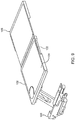
- the table extension 108 is shown fully deployed, thus substantially doubling the surface area of the main table 102.
- the table extension 108 deploys from a stowed position below the main table 102 to a fully deployed position laterally-adjacent the main table 102.
- the main table or a portion thereof lowers into place such that the top surface of the main table 102 is horizontally aligned with a top surface of the table extension 108 to provide a substantially continuous table surface.
- the adjoining sides of the main table 102 and the table extension 108 are in direct physical contact to avoid or minimize any gap between the table tops.
- the deployment sequence can be reversed to stow the tray table 100.
- FIGS. 5 and 6 further illustrate the tray table 100, albeit showing the drawer slides disconnected from the hinge base 104.
- the table top can have three usable surfaces when the tray table is farthest from the attached seat back, and two usable surfaces when the tray table is closest to the seat back.
- the tray table 100 can slide relative to the hinge base 104 regardless of whether the table extension 108 is stowed or deployed, allowing seat egress without having to fully stow the tray table.
- the tray table 100 generally includes the main table 102, the table extension 108, and an intermediate support 110.
- the intermediate support 110 can be provided as a unitary component or separate spaced apart components.
- the intermediate support 110 is disposed between the main table 102 and the table extensionm108, as is slidably coupled to each of the main table 102 and the table extension 108.
- the intermediate support generally includes first and second parallel guide rails each slidably coupled to each of the main table 102 and the table extension108, or as shown, a first part 112 slidably coupled to the main table 102 and a guide block 114 slidably coupled to the table extension 108.
- the main table 102 includes first and second elongate parallel guides 116 within which the respective first and second guide rails slide to translate the intermediate support 110 relative to the main table 102
- the table extension 108 includes first and second elongate parallel guides 118 within which the respective first and second guide rails slide to translate the table extension 108 relative to the intermediate support 110.
- the first guide of the main table, the first guide of the table extension, and the first guide rail may be linearly aligned, while the second guide of the main table, the second guide of the table extension, and the second guide rail may also be linearly aligned, thus maintaining squareness as the table extension stows and deploys.
- a tray table assembly, or tray table 200 may be translationally coupled to the hinge 220 to permit fore and aft positioning, and may also be rotationally coupled to the hinge 220 to permit the tray table to rotate between vertical and horizontal orientations for respective stowing and use.
- the hinge 220 may attach near one side of the bottom of the tray table, and the tray table may extend away from the hinge to position the tray table, in use, in an over-seat position.
- the tray table 200 shown in FIG. 7 is deployed, but with the table extension fully stowed.
- the table extension 208 deploys from a stowed position below the main table 202 to the partially deployed position shown by sliding apart from the main table 202.
- the main table 202 includes a base 222 and a table top 224, the table top configured to lower onto the base 222 when the table extension is laterally adjacent and clear of the main table 202 such that a top surface of the table extension and a top surface of the table top horizontally align when the table extension 208 is fully deployed.
- the table extension 208 may stow between the base 222 and the table top 224, and deploys to a position laterally-adjacent the main table 202.
- the table top 224 may be coupled to the base 222 through links or a pivot that allows the table top to move up and down with low friction and positive location.
- the table extension 208 is shown fully deployed and laterally adjacent the main table 202, and the table top 224 is shown lowered into position horizontally aligned with the table extension 208.
- An edge of the main table 202 facing the table extension 208 when fully deployed may be ramped to facilitate and guide table extension movement toward the stowed position thereof.
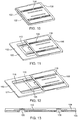
- FIGS. 10-12 show a particular guide rail configuration and tray extension deployment motion for example of the tray table 100, but also applicable to the tray table 200.
- FIG. 10 shows the table extension 108 fully stowed below the main table 102 or base 122.
- the main table 102 includes first and second elongate parallel guides 116 within which the respective first and second guide rails 126 of the intermediate support 110 slide to translate the intermediate support 110 relative to the main table 102 or base 122
- the table extension 108 includes first and second elongate parallel guides 118 within which the respective first and second guide rails 126 slide to translate the table extension 108 relative to the intermediate support 110.
- the intermediate support 110 stows in a recess defined in the table extension to achieve a thin vertical profile.
- Stops may be provided to limit travel of the guide rails within their respective guides.
- the guide length may be determinative of the length of travel, which can be customized. Referring to FIG. 13 , the sectional view through the tray table 100 illustrates the thin vertical profile and guide rail arrangement with respect to the main table 102 and table extension 108.
Landscapes
- Engineering & Computer Science (AREA)
- Aviation & Aerospace Engineering (AREA)
- Transportation (AREA)
- Mechanical Engineering (AREA)
- Passenger Equipment (AREA)
- Vehicle Step Arrangements And Article Storage (AREA)
Applications Claiming Priority (1)
| Application Number | Priority Date | Filing Date | Title |
|---|---|---|---|
| US15/949,717 US10625649B2 (en) | 2018-04-10 | 2018-04-10 | Mechanism to achieve expandable tray table |
Publications (2)
| Publication Number | Publication Date |
|---|---|
| EP3552968A1 true EP3552968A1 (de) | 2019-10-16 |
| EP3552968B1 EP3552968B1 (de) | 2022-01-12 |
Family
ID=66104999
Family Applications (1)
| Application Number | Title | Priority Date | Filing Date |
|---|---|---|---|
| EP19168299.6A Active EP3552968B1 (de) | 2018-04-10 | 2019-04-10 | Mechanismus zur erzielung eines expandierbaren tabletttischs |
Country Status (2)
| Country | Link |
|---|---|
| US (1) | US10625649B2 (de) |
| EP (1) | EP3552968B1 (de) |
Families Citing this family (15)
| Publication number | Priority date | Publication date | Assignee | Title |
|---|---|---|---|---|
| DE102017117173A1 (de) * | 2017-07-28 | 2019-01-31 | Recaro Aircraft Seating Gmbh & Co. Kg | Tischvorrichtung |
| CN110723044A (zh) * | 2018-07-17 | 2020-01-24 | 丰田纺织株式会社 | 桌板装置 |
| WO2020039237A1 (en) * | 2018-08-24 | 2020-02-27 | Safran Seats Usa Llc | Secondary personal item support |
| US11458867B2 (en) * | 2019-01-07 | 2022-10-04 | Adient Us Llc | Occupant support component for a seat of a vehicle and vehicle seat |
| US11072264B2 (en) * | 2019-07-09 | 2021-07-27 | Lear Corporation | Protective assembly |
| US11963634B2 (en) * | 2020-01-27 | 2024-04-23 | North Atlantic Imports, Llc | Adjustable warming rack and method thereof |
| US11565818B2 (en) * | 2020-04-13 | 2023-01-31 | Adient Aerospace, Llc | Tray table apparatus for a console element, console element and seat unit |
| US11161459B1 (en) * | 2020-05-29 | 2021-11-02 | Clem Tucker | Adjustable seat tray |
| FR3116809B1 (fr) * | 2020-11-30 | 2023-11-17 | Safran Seats | Console pour une unité de siège munie d'un bras de support d'un dispositif electronique portatif |
| US12179702B2 (en) * | 2022-07-27 | 2024-12-31 | Hyundai Motor Company | Convertible covering shelf structure |
| JP2024099964A (ja) * | 2023-01-13 | 2024-07-26 | トヨタ紡織株式会社 | シートバックテーブル用ロック装置 |
| IT202300006606A1 (it) * | 2023-04-04 | 2024-10-04 | Goood S R L | Parete per schienali di sedute per aerei |
| EP4620815A1 (de) * | 2024-03-18 | 2025-09-24 | B/E Aerospace, Inc. | Tisch |
| FR3161541A1 (fr) | 2024-04-29 | 2025-10-31 | Airbus Atlantic | Ensemble de table repas escamotable à clapet coulissant et unité de siège comprenant un tel ensemble |
| US20260028123A1 (en) * | 2024-07-24 | 2026-01-29 | B/E Aerospace, Inc. | Aircraft seatback tray table module |
Citations (6)
| Publication number | Priority date | Publication date | Assignee | Title |
|---|---|---|---|---|
| US2199981A (en) * | 1936-11-23 | 1940-05-07 | Heywood Wakefield Co | Wall cabinet table |
| US2536366A (en) * | 1945-06-22 | 1951-01-02 | Makmoroom Ltd | Folding extension table sectional top |
| DE4227064A1 (de) * | 1992-08-15 | 1993-10-14 | Daimler Benz Ag | Klapptisch |
| DE102004046044A1 (de) * | 2004-09-21 | 2006-03-30 | Vogelsitze Gmbh | Fahrgastsitz mit Rückenlehnentisch |
| KR20140066076A (ko) * | 2012-11-22 | 2014-05-30 | 고영철 | 보조책상 |
| US20170021931A1 (en) * | 2014-04-07 | 2017-01-26 | B/E Aerospace, Inc. | Laterally-expanding tray table |
Family Cites Families (19)
| Publication number | Priority date | Publication date | Assignee | Title |
|---|---|---|---|---|
| US1160125A (en) * | 1913-10-10 | 1915-11-16 | Gen Acoustic Company | Dictograph intercommunicating telephone system. |
| US1151940A (en) * | 1914-09-24 | 1915-08-31 | Jules Gauvreau | Identification-tag. |
| US2168210A (en) * | 1937-07-29 | 1939-08-01 | Hawksley Ralph Goodwin | Utility table for motor vehicles |
| US2554685A (en) * | 1948-09-11 | 1951-05-29 | Denis Alcide Ovide St | Detachable tray for the inside of motor vehicle doors |
| GB1151940A (en) * | 1966-12-24 | 1969-05-14 | Hallam Sleigh & Cheston Ltd | Pic-Nic Table for use in a Motor-Car |
| US3847462A (en) * | 1972-02-14 | 1974-11-12 | Olivetti & Co Spa | Sliding drawer for tables and office desks |
| US4174669A (en) * | 1978-02-22 | 1979-11-20 | Lalonde A Roger | Vehicle tray and mounting bracket assembly |
| US5443018A (en) * | 1993-11-15 | 1995-08-22 | Cromwell; Carl E. | Folding tray for attachment to a vehicle seat back |
| JP2934808B2 (ja) * | 1994-05-23 | 1999-08-16 | テイ・エス テック株式会社 | 車装用テーブル設備 |
| US5820194A (en) * | 1995-01-23 | 1998-10-13 | Monaco Coach Corporation | Passenger sliding tray |
| US5931527A (en) * | 1996-05-03 | 1999-08-03 | D'onofrio; Giulio | Seat back mounted cargo shelf |
| US6394001B1 (en) * | 2000-05-16 | 2002-05-28 | Daimlerchrysler Corporation | Vehicle table apparatus |
| DE10026561A1 (de) * | 2000-05-27 | 2001-12-06 | Daimler Chrysler Ag | Klapptischanordnung für Fahrzeuge |
| US8596206B2 (en) * | 2011-01-03 | 2013-12-03 | Zodiac Seats France | Tray table assembly |
| US8997660B2 (en) * | 2012-03-23 | 2015-04-07 | Johnny A. Satterfield | Deployable table assembly |
| US9573687B2 (en) * | 2014-04-07 | 2017-02-21 | B/E Aerospace, Inc. | Laterally-expanding tray table |
| JP6708948B2 (ja) * | 2016-01-21 | 2020-06-10 | 日本電気株式会社 | ブロックストレージ |
| DE102016011850B4 (de) * | 2016-10-01 | 2021-09-02 | Daimler Ag | Kraftfahrzeug mit einer Ablageeinrichtung |
| US10285495B1 (en) * | 2017-09-06 | 2019-05-14 | Ronald Joseph Valme | Portable desk tray table |
-
2018
- 2018-04-10 US US15/949,717 patent/US10625649B2/en active Active
-
2019
- 2019-04-10 EP EP19168299.6A patent/EP3552968B1/de active Active
Patent Citations (6)
| Publication number | Priority date | Publication date | Assignee | Title |
|---|---|---|---|---|
| US2199981A (en) * | 1936-11-23 | 1940-05-07 | Heywood Wakefield Co | Wall cabinet table |
| US2536366A (en) * | 1945-06-22 | 1951-01-02 | Makmoroom Ltd | Folding extension table sectional top |
| DE4227064A1 (de) * | 1992-08-15 | 1993-10-14 | Daimler Benz Ag | Klapptisch |
| DE102004046044A1 (de) * | 2004-09-21 | 2006-03-30 | Vogelsitze Gmbh | Fahrgastsitz mit Rückenlehnentisch |
| KR20140066076A (ko) * | 2012-11-22 | 2014-05-30 | 고영철 | 보조책상 |
| US20170021931A1 (en) * | 2014-04-07 | 2017-01-26 | B/E Aerospace, Inc. | Laterally-expanding tray table |
Non-Patent Citations (1)
| Title |
|---|
| DENNIS BUNNIK: "Lufthansa Business Class A380", 18 August 2017 (2017-08-18), XP054979610, Retrieved from the Internet <URL:https://www.youtube.com/watch?v=838_QDz9BLc> [retrieved on 20190821] * |
Also Published As
| Publication number | Publication date |
|---|---|
| US10625649B2 (en) | 2020-04-21 |
| EP3552968B1 (de) | 2022-01-12 |
| US20190308538A1 (en) | 2019-10-10 |
Similar Documents
| Publication | Publication Date | Title |
|---|---|---|
| EP3552968B1 (de) | Mechanismus zur erzielung eines expandierbaren tabletttischs | |
| US10875652B2 (en) | Passenger tray table | |
| EP3128873B1 (de) | Seitlich expandierender serviertisch | |
| US9919802B2 (en) | Laterally-expanding tray table | |
| CN104284837B (zh) | 悬臂托盘桌以及包括该悬臂托盘桌的飞机乘客套间 | |
| EP2646318B1 (de) | Klapptisch für einen passagiersitz | |
| US8596206B2 (en) | Tray table assembly | |
| EP2981469B1 (de) | Vertikal verstaute traytischanordnung mit translationsbewegung | |
| US10023315B2 (en) | Passenger seat table assembly | |
| US9820568B2 (en) | Integral tray table personal electronic device holder and tray table | |
| US10342338B2 (en) | Stowage module mounted tray table with multi-bar linkage driven movement | |
| US20180116391A1 (en) | Table For Aircraft Interiors | |
| US10370107B2 (en) | Arced rail for aircraft tray table | |
| US20230182632A1 (en) | Foldable ped holder | |
| US12202605B2 (en) | Retractable divider for passenger seat | |
| EP4385898A1 (de) | Serviertisch für schrägsitzanlagen und schrägsitzanlagen | |
| EP4263351B1 (de) | Flugzeugsitzkonstruktion mit montierbarer lebensmittelschale | |
| US11912186B2 (en) | Modular tray table with rotational displacement mechanism | |
| EP3282891B1 (de) | Aufklappbarer esstisch | |
| EP4474278B1 (de) | Passagiersuite mit sekundärem sitz und komfort |
Legal Events
| Date | Code | Title | Description |
|---|---|---|---|
| PUAI | Public reference made under article 153(3) epc to a published international application that has entered the european phase |
Free format text: ORIGINAL CODE: 0009012 |
|
| STAA | Information on the status of an ep patent application or granted ep patent |
Free format text: STATUS: THE APPLICATION HAS BEEN PUBLISHED |
|
| AK | Designated contracting states |
Kind code of ref document: A1 Designated state(s): AL AT BE BG CH CY CZ DE DK EE ES FI FR GB GR HR HU IE IS IT LI LT LU LV MC MK MT NL NO PL PT RO RS SE SI SK SM TR |
|
| AX | Request for extension of the european patent |
Extension state: BA ME |
|
| STAA | Information on the status of an ep patent application or granted ep patent |
Free format text: STATUS: REQUEST FOR EXAMINATION WAS MADE |
|
| 17P | Request for examination filed |
Effective date: 20200416 |
|
| RBV | Designated contracting states (corrected) |
Designated state(s): AL AT BE BG CH CY CZ DE DK EE ES FI FR GB GR HR HU IE IS IT LI LT LU LV MC MK MT NL NO PL PT RO RS SE SI SK SM TR |
|
| STAA | Information on the status of an ep patent application or granted ep patent |
Free format text: STATUS: EXAMINATION IS IN PROGRESS |
|
| 17Q | First examination report despatched |
Effective date: 20200817 |
|
| GRAP | Despatch of communication of intention to grant a patent |
Free format text: ORIGINAL CODE: EPIDOSNIGR1 |
|
| STAA | Information on the status of an ep patent application or granted ep patent |
Free format text: STATUS: GRANT OF PATENT IS INTENDED |
|
| INTG | Intention to grant announced |
Effective date: 20210906 |
|
| RIN1 | Information on inventor provided before grant (corrected) |
Inventor name: SUHRE, RYAN J. Inventor name: STUTTGEN, JOSEPH M. Inventor name: BUCHANAN, TYLER P. |
|
| GRAS | Grant fee paid |
Free format text: ORIGINAL CODE: EPIDOSNIGR3 |
|
| GRAA | (expected) grant |
Free format text: ORIGINAL CODE: 0009210 |
|
| STAA | Information on the status of an ep patent application or granted ep patent |
Free format text: STATUS: THE PATENT HAS BEEN GRANTED |
|
| AK | Designated contracting states |
Kind code of ref document: B1 Designated state(s): AL AT BE BG CH CY CZ DE DK EE ES FI FR GB GR HR HU IE IS IT LI LT LU LV MC MK MT NL NO PL PT RO RS SE SI SK SM TR |
|
| REG | Reference to a national code |
Ref country code: GB Ref legal event code: FG4D |
|
| REG | Reference to a national code |
Ref country code: CH Ref legal event code: EP |
|
| REG | Reference to a national code |
Ref country code: DE Ref legal event code: R096 Ref document number: 602019010774 Country of ref document: DE |
|
| REG | Reference to a national code |
Ref country code: IE Ref legal event code: FG4D |
|
| REG | Reference to a national code |
Ref country code: AT Ref legal event code: REF Ref document number: 1462212 Country of ref document: AT Kind code of ref document: T Effective date: 20220215 |
|
| REG | Reference to a national code |
Ref country code: LT Ref legal event code: MG9D |
|
| REG | Reference to a national code |
Ref country code: NL Ref legal event code: MP Effective date: 20220112 |
|
| REG | Reference to a national code |
Ref country code: AT Ref legal event code: MK05 Ref document number: 1462212 Country of ref document: AT Kind code of ref document: T Effective date: 20220112 |
|
| PG25 | Lapsed in a contracting state [announced via postgrant information from national office to epo] |
Ref country code: NL Free format text: LAPSE BECAUSE OF FAILURE TO SUBMIT A TRANSLATION OF THE DESCRIPTION OR TO PAY THE FEE WITHIN THE PRESCRIBED TIME-LIMIT Effective date: 20220112 |
|
| PG25 | Lapsed in a contracting state [announced via postgrant information from national office to epo] |
Ref country code: SE Free format text: LAPSE BECAUSE OF FAILURE TO SUBMIT A TRANSLATION OF THE DESCRIPTION OR TO PAY THE FEE WITHIN THE PRESCRIBED TIME-LIMIT Effective date: 20220112 Ref country code: RS Free format text: LAPSE BECAUSE OF FAILURE TO SUBMIT A TRANSLATION OF THE DESCRIPTION OR TO PAY THE FEE WITHIN THE PRESCRIBED TIME-LIMIT Effective date: 20220112 Ref country code: PT Free format text: LAPSE BECAUSE OF FAILURE TO SUBMIT A TRANSLATION OF THE DESCRIPTION OR TO PAY THE FEE WITHIN THE PRESCRIBED TIME-LIMIT Effective date: 20220512 Ref country code: NO Free format text: LAPSE BECAUSE OF FAILURE TO SUBMIT A TRANSLATION OF THE DESCRIPTION OR TO PAY THE FEE WITHIN THE PRESCRIBED TIME-LIMIT Effective date: 20220412 Ref country code: LT Free format text: LAPSE BECAUSE OF FAILURE TO SUBMIT A TRANSLATION OF THE DESCRIPTION OR TO PAY THE FEE WITHIN THE PRESCRIBED TIME-LIMIT Effective date: 20220112 Ref country code: HR Free format text: LAPSE BECAUSE OF FAILURE TO SUBMIT A TRANSLATION OF THE DESCRIPTION OR TO PAY THE FEE WITHIN THE PRESCRIBED TIME-LIMIT Effective date: 20220112 Ref country code: ES Free format text: LAPSE BECAUSE OF FAILURE TO SUBMIT A TRANSLATION OF THE DESCRIPTION OR TO PAY THE FEE WITHIN THE PRESCRIBED TIME-LIMIT Effective date: 20220112 Ref country code: BG Free format text: LAPSE BECAUSE OF FAILURE TO SUBMIT A TRANSLATION OF THE DESCRIPTION OR TO PAY THE FEE WITHIN THE PRESCRIBED TIME-LIMIT Effective date: 20220412 |
|
| PG25 | Lapsed in a contracting state [announced via postgrant information from national office to epo] |
Ref country code: PL Free format text: LAPSE BECAUSE OF FAILURE TO SUBMIT A TRANSLATION OF THE DESCRIPTION OR TO PAY THE FEE WITHIN THE PRESCRIBED TIME-LIMIT Effective date: 20220112 Ref country code: LV Free format text: LAPSE BECAUSE OF FAILURE TO SUBMIT A TRANSLATION OF THE DESCRIPTION OR TO PAY THE FEE WITHIN THE PRESCRIBED TIME-LIMIT Effective date: 20220112 Ref country code: GR Free format text: LAPSE BECAUSE OF FAILURE TO SUBMIT A TRANSLATION OF THE DESCRIPTION OR TO PAY THE FEE WITHIN THE PRESCRIBED TIME-LIMIT Effective date: 20220413 Ref country code: FI Free format text: LAPSE BECAUSE OF FAILURE TO SUBMIT A TRANSLATION OF THE DESCRIPTION OR TO PAY THE FEE WITHIN THE PRESCRIBED TIME-LIMIT Effective date: 20220112 Ref country code: AT Free format text: LAPSE BECAUSE OF FAILURE TO SUBMIT A TRANSLATION OF THE DESCRIPTION OR TO PAY THE FEE WITHIN THE PRESCRIBED TIME-LIMIT Effective date: 20220112 |
|
| PG25 | Lapsed in a contracting state [announced via postgrant information from national office to epo] |
Ref country code: IS Free format text: LAPSE BECAUSE OF FAILURE TO SUBMIT A TRANSLATION OF THE DESCRIPTION OR TO PAY THE FEE WITHIN THE PRESCRIBED TIME-LIMIT Effective date: 20220512 |
|
| REG | Reference to a national code |
Ref country code: DE Ref legal event code: R097 Ref document number: 602019010774 Country of ref document: DE |
|
| PG25 | Lapsed in a contracting state [announced via postgrant information from national office to epo] |
Ref country code: SM Free format text: LAPSE BECAUSE OF FAILURE TO SUBMIT A TRANSLATION OF THE DESCRIPTION OR TO PAY THE FEE WITHIN THE PRESCRIBED TIME-LIMIT Effective date: 20220112 Ref country code: SK Free format text: LAPSE BECAUSE OF FAILURE TO SUBMIT A TRANSLATION OF THE DESCRIPTION OR TO PAY THE FEE WITHIN THE PRESCRIBED TIME-LIMIT Effective date: 20220112 Ref country code: RO Free format text: LAPSE BECAUSE OF FAILURE TO SUBMIT A TRANSLATION OF THE DESCRIPTION OR TO PAY THE FEE WITHIN THE PRESCRIBED TIME-LIMIT Effective date: 20220112 Ref country code: EE Free format text: LAPSE BECAUSE OF FAILURE TO SUBMIT A TRANSLATION OF THE DESCRIPTION OR TO PAY THE FEE WITHIN THE PRESCRIBED TIME-LIMIT Effective date: 20220112 Ref country code: DK Free format text: LAPSE BECAUSE OF FAILURE TO SUBMIT A TRANSLATION OF THE DESCRIPTION OR TO PAY THE FEE WITHIN THE PRESCRIBED TIME-LIMIT Effective date: 20220112 Ref country code: CZ Free format text: LAPSE BECAUSE OF FAILURE TO SUBMIT A TRANSLATION OF THE DESCRIPTION OR TO PAY THE FEE WITHIN THE PRESCRIBED TIME-LIMIT Effective date: 20220112 |
|
| PLBE | No opposition filed within time limit |
Free format text: ORIGINAL CODE: 0009261 |
|
| STAA | Information on the status of an ep patent application or granted ep patent |
Free format text: STATUS: NO OPPOSITION FILED WITHIN TIME LIMIT |
|
| PG25 | Lapsed in a contracting state [announced via postgrant information from national office to epo] |
Ref country code: AL Free format text: LAPSE BECAUSE OF FAILURE TO SUBMIT A TRANSLATION OF THE DESCRIPTION OR TO PAY THE FEE WITHIN THE PRESCRIBED TIME-LIMIT Effective date: 20220112 |
|
| REG | Reference to a national code |
Ref country code: CH Ref legal event code: PL |
|
| 26N | No opposition filed |
Effective date: 20221013 |
|
| REG | Reference to a national code |
Ref country code: BE Ref legal event code: MM Effective date: 20220430 |
|
| PG25 | Lapsed in a contracting state [announced via postgrant information from national office to epo] |
Ref country code: MC Free format text: LAPSE BECAUSE OF FAILURE TO SUBMIT A TRANSLATION OF THE DESCRIPTION OR TO PAY THE FEE WITHIN THE PRESCRIBED TIME-LIMIT Effective date: 20220112 Ref country code: LU Free format text: LAPSE BECAUSE OF NON-PAYMENT OF DUE FEES Effective date: 20220410 Ref country code: LI Free format text: LAPSE BECAUSE OF NON-PAYMENT OF DUE FEES Effective date: 20220430 Ref country code: CH Free format text: LAPSE BECAUSE OF NON-PAYMENT OF DUE FEES Effective date: 20220430 |
|
| PG25 | Lapsed in a contracting state [announced via postgrant information from national office to epo] |
Ref country code: SI Free format text: LAPSE BECAUSE OF FAILURE TO SUBMIT A TRANSLATION OF THE DESCRIPTION OR TO PAY THE FEE WITHIN THE PRESCRIBED TIME-LIMIT Effective date: 20220112 Ref country code: BE Free format text: LAPSE BECAUSE OF NON-PAYMENT OF DUE FEES Effective date: 20220430 |
|
| PG25 | Lapsed in a contracting state [announced via postgrant information from national office to epo] |
Ref country code: IE Free format text: LAPSE BECAUSE OF NON-PAYMENT OF DUE FEES Effective date: 20220410 |
|
| PG25 | Lapsed in a contracting state [announced via postgrant information from national office to epo] |
Ref country code: IT Free format text: LAPSE BECAUSE OF FAILURE TO SUBMIT A TRANSLATION OF THE DESCRIPTION OR TO PAY THE FEE WITHIN THE PRESCRIBED TIME-LIMIT Effective date: 20220112 |
|
| PG25 | Lapsed in a contracting state [announced via postgrant information from national office to epo] |
Ref country code: HU Free format text: LAPSE BECAUSE OF FAILURE TO SUBMIT A TRANSLATION OF THE DESCRIPTION OR TO PAY THE FEE WITHIN THE PRESCRIBED TIME-LIMIT; INVALID AB INITIO Effective date: 20190410 |
|
| PG25 | Lapsed in a contracting state [announced via postgrant information from national office to epo] |
Ref country code: MK Free format text: LAPSE BECAUSE OF FAILURE TO SUBMIT A TRANSLATION OF THE DESCRIPTION OR TO PAY THE FEE WITHIN THE PRESCRIBED TIME-LIMIT Effective date: 20220112 Ref country code: CY Free format text: LAPSE BECAUSE OF FAILURE TO SUBMIT A TRANSLATION OF THE DESCRIPTION OR TO PAY THE FEE WITHIN THE PRESCRIBED TIME-LIMIT Effective date: 20220112 |
|
| PG25 | Lapsed in a contracting state [announced via postgrant information from national office to epo] |
Ref country code: MT Free format text: LAPSE BECAUSE OF FAILURE TO SUBMIT A TRANSLATION OF THE DESCRIPTION OR TO PAY THE FEE WITHIN THE PRESCRIBED TIME-LIMIT Effective date: 20220112 |
|
| PGFP | Annual fee paid to national office [announced via postgrant information from national office to epo] |
Ref country code: DE Payment date: 20250319 Year of fee payment: 7 |
|
| PG25 | Lapsed in a contracting state [announced via postgrant information from national office to epo] |
Ref country code: TR Free format text: LAPSE BECAUSE OF FAILURE TO SUBMIT A TRANSLATION OF THE DESCRIPTION OR TO PAY THE FEE WITHIN THE PRESCRIBED TIME-LIMIT Effective date: 20220112 |
|
| P01 | Opt-out of the competence of the unified patent court (upc) registered |
Free format text: CASE NUMBER: UPC_APP_0017967_3552968/2025 Effective date: 20251217 |
|
| PGFP | Annual fee paid to national office [announced via postgrant information from national office to epo] |
Ref country code: GB Payment date: 20260319 Year of fee payment: 8 |
|
| PGFP | Annual fee paid to national office [announced via postgrant information from national office to epo] |
Ref country code: FR Payment date: 20260320 Year of fee payment: 8 |