EP3552938A1 - Fork-frame unit - Google Patents
Fork-frame unit Download PDFInfo
- Publication number
- EP3552938A1 EP3552938A1 EP19167810.1A EP19167810A EP3552938A1 EP 3552938 A1 EP3552938 A1 EP 3552938A1 EP 19167810 A EP19167810 A EP 19167810A EP 3552938 A1 EP3552938 A1 EP 3552938A1
- Authority
- EP
- European Patent Office
- Prior art keywords
- tube
- fork
- control
- frame
- control means
- Prior art date
- Legal status (The legal status is an assumption and is not a legal conclusion. Google has not performed a legal analysis and makes no representation as to the accuracy of the status listed.)
- Granted
Links
Images

Classifications
-
- B—PERFORMING OPERATIONS; TRANSPORTING
- B62—LAND VEHICLES FOR TRAVELLING OTHERWISE THAN ON RAILS
- B62J—CYCLE SADDLES OR SEATS; AUXILIARY DEVICES OR ACCESSORIES SPECIALLY ADAPTED TO CYCLES AND NOT OTHERWISE PROVIDED FOR, e.g. ARTICLE CARRIERS OR CYCLE PROTECTORS
- B62J11/00—Supporting arrangements specially adapted for fastening specific devices to cycles, e.g. supports for attaching maps
- B62J11/10—Supporting arrangements specially adapted for fastening specific devices to cycles, e.g. supports for attaching maps for mechanical cables, hoses, pipes or electric wires, e.g. cable guides
- B62J11/13—Supporting arrangements specially adapted for fastening specific devices to cycles, e.g. supports for attaching maps for mechanical cables, hoses, pipes or electric wires, e.g. cable guides specially adapted for mechanical cables
-
- B—PERFORMING OPERATIONS; TRANSPORTING
- B62—LAND VEHICLES FOR TRAVELLING OTHERWISE THAN ON RAILS
- B62K—CYCLES; CYCLE FRAMES; CYCLE STEERING DEVICES; RIDER-OPERATED TERMINAL CONTROLS SPECIALLY ADAPTED FOR CYCLES; CYCLE AXLE SUSPENSIONS; CYCLE SIDE-CARS, FORECARS, OR THE LIKE
- B62K19/00—Cycle frames
- B62K19/30—Frame parts shaped to receive other cycle parts or accessories
- B62K19/32—Steering heads
Definitions
- the invention relates to a fork-frame unit for a two- or three-wheeler, with a vehicle frame with a control tube connected to at least one frame tube and with a vehicle fork having a steerer, which is centered in the head tube by means of a headset and stored rotatably mounted wherein the headset has at least one control bearing disposed in the control tube and at least one cooperating with the control bearing, arranged on the steerer centering ring having at least one passage for at least one displaced from the outside into the interior of the vehicle frame, flexible control means.
- Control means such as electrical cable connections or brake and circuit cables, which are taken leksbeweglinger in Bowdenzigüllen lead in bicycles and especially in wheels with electric auxiliary motor (pedelec) from the driver to various vehicle components such as derailleurs, derailleurs, brakes, the optional electric auxiliary drive and its built-in battery in the vehicle frame. Efforts have been made for some time to relocate these control means, which were traditionally led along the outside of the vehicle frame, into its interior, in order to protect it from dirt and moisture.
- openings have been provided in the past at suitable locations in the frame tubes into which the control arms emanating from the handlebars, which were initially exposed there, have been introduced into the interior of the frame, at another point in the vicinity of the vehicle components to be actuated by the respective control means the frame inside to be led out through a corresponding opening.
- the control means the electrical lines between the electric motor, battery and their display and actuator on the handlebars have the subject to introduce directly to the handlebar stem in the frame interior by the control means by one at the upper centering (centering cone ) of the headset provided passage outside of the steerer tube enters the head tube of the vehicle frame and from there into the welded on the head tube, usually lower frame tube of the vehicle frame is performed ("Total Integration Concept" the company Thömus Bikes).
- the well-known design ensures a tidy looking cable management, but carries the risk that the guided through the centering ring inside the control means rubbing due to the relative movements occurring between the head tube and the steerer tube at steering angles on the outer circumference of the steerer tube or inside the head tube and thereby damaged.
- the object of the invention is to protect the control means against such damage.
- At least one protective cuff for the control means arranged in the interior of the control tube between the latter and the steerer tube.
- Such a protective cuff prevents the direct contact between the control means, ie in particular from the outside through the Centering ring in the frame interior in the space between the steerer tube and steering tube inserted electrical line with the outside of the steerer tube and / or the inside of the head tube.
- the protective cuff may preferably be arranged between the control means and the steerer tube surrounding it, it is also possible that the protective cuff between the control means and the control tube, this inside at least over a part of its length is arranged circumferentially shielding.
- two substantially concentric protective cuffs are provided, between which extends the at least one control means in the interior of the head tube. In this embodiment, the control means is then protected both inwardly relative to the steerer tube rotatably received in the control tube and outwardly against the inner wall of the control tube.
- the protective cuff can be deformable at least in the circumferential direction and preferably at least partially consist of a plastically deformable material, in particular of plastic or an elastomer material.
- the protective cuff consists of a woven or knitted fabric which is arranged in a grid or net shape between the steerer tube and the control means or between the latter and the control tube.
- Such a fabric or knit can be deformed (twisting) in its circumferential direction with only very little effort, especially if the longitudinally parallel to the control axis threads or rods of fabric or knitted fabric with the circumferentially extending thereto layers have no firm connection, but only intertwined with each other.
- any influence of the protective cuff (s) on the steering forces to be exerted by the driver of the vehicle remains negligibly small.
- the protective cuff is connected at its one, in particular upper end fixed to the centering ring. It then forms with the centering an integral component, which can facilitate the assembly inside the head tube considerably.
- the protective cuff is made of plastic and is molded on the centering ring.
- the arranged between the control tube and the control means protective cuff is provided with a projecting into the interior of the frame tube extension which thus in the sometimes sharp edges having transition region between the frame tube and control tube to line this and is able to prevent direct contact between the control means and the sharp edges of the transition region.
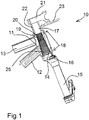
- Fig. 1 10 denotes a fork-frame unit according to the invention for a bicycle provided with an electric auxiliary motor (not shown), a so-called pedelec, in which the pedaling movement of the driver is assisted by an electric motor, which derives its electrical energy from a battery attached to the bicycle frame or its luggage rack.
- the fork-frame unit 10 consists essentially of a vehicle frame 11 with a lower frame tube 12 and an upper frame tube 13, at the respective front ends in a known manner a control tube 14 for receiving a vehicle fork 15 is arranged.
- the vehicle fork is, as generally known in bicycles or similar two- or three-wheeled vehicles inserted with their upwardly from the fork bridge 16 uprights 17 in the steering tube 14 from below, being centered by a headset 18 and rotatably mounted in the control tube ,
- the headset in a known manner, a first, recorded below the head tube control bearing (not shown in detail) and a second, upper control bearing 19 which is received at the upper end in the control tube 14 and into which a conical centering ring 20, from above is fitted on the steerer 17, framed, so that the vehicle fork 15 is mounted concentrically with the axis of the control tube in this.
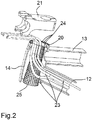
- the unit 10 is a plurality of flexible control means, namely electrical cables 23, which are guided between the drive auxiliary motor and its battery (both not shown) and the handlebar of the vehicle, also not shown, of the stem 21 is attached, provided.
- the cables 23 run inside the frame through the lower frame tube 12, at the front end they enter the control tube 14 in the intermediate space between this and the fork tube 17 received in the control tube and through the centering ring 20 upwards out of the head tube 14 are led out.
- the centering ring 20 is provided with a plurality of passages 24 in the form of distributed over its circumference arranged holes through which the cables 23 are inserted so that they are neatly side by side and without crossing over each other.
- a protective cuff 25 extending over the entire height of the steerer tube inside the head tube and made of a resilient plastic material at least in the circumferential direction is elastically deformable.
- the cable 23 can create when the fork is twisted in the steering tube when driving the vehicle, without the risk that they chafe this or otherwise damaged.
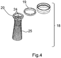
- the protective cuff 25 is made of a flexible fabric or a knitted fabric, which is reticularly put over the steerer 17.
- the arrangement is made such that the approximately vertically parallel to the axis of the steerer tube 17 and the surrounding control tube 14 extending threads or webs of this knitted fabric formed directly on the centering ring 20, for example, are molded, so that the protective cuff 25 with the centering ring 20 a uniform component ( Fig. 4 ).
- the arrangement according to the invention reliably ensures that the cables 23 guided from above through the centering ring 20 into the space between the inner wall of the control tube 14 and the outside of the steerer tube 17 are not damaged by the rotation of the fork relative to the frame become. It is possible, in addition to or as an alternative to the one protective cuff 25 which underlays the cables 23 inwardly toward the steerer, to provide an outer protective cuff between the control tube 14 and the control means 23 so that they do not make direct contact with the inside of the steerer tube Control tube 14 may have.
- outer protective cuff can be provided with a protruding into the lower frame tube 12 extension, so that even in the transition between the control tube 14 and frame tube 12 no direct contact between the vehicle frame and guided by this control means may arise, but they are reliably secured against damage here.
Abstract
Bei einer Gabel-Rahmen-Einheit (10) für ein zwei- oder dreirädriges Fahrzeug, bei dem eine Fahrzeuggabel (15) mit ihrem Gabelschaft (17) in einem Steuerrohr (14) des Rahmens drehbar gelagert aufgenommen ist und bei der mindestens ein flexibles Steuermittel wie beispielsweise ein elektrisches Kabel (23) durch einen Zentrierring (20) von außen ins Innere des Rahmens in den Zwischenraum zwischen der Innenseite des Steuerrohrs und der Außenseite des Gabelschafts geführt ist, ist erfindungsgemäß vorgesehen, dass mindestens eine im Inneren des Steuerrohrs zwischen diesem und dem Gabelschaft angeordnete Schutzstulpe (25) für das Steuermittel vorgesehen ist, die eine Beschädigung des Steuermittels wirksam verhindert. (Hierzu Fig. 1)In the case of a fork-frame unit (10) for a two- or three-wheel vehicle, in which a vehicle fork (15) with its fork shaft (17) is rotatably received in a head tube (14) of the frame and in which at least one flexible control means How, for example, an electrical cable (23) is guided through a centering ring (20) from the outside into the interior of the frame into the space between the inside of the head tube and the outside of the steerer tube, the invention provides that at least one inside the head tube between it and the steerer tube is provided with a protective cuff (25) which effectively prevents damage to the control means. (See Fig. 1)
Description
Die Erfindung betrifft eine Gabel-Rahmen-Einheit für ein Zwei- oder Dreirad, mit einem Fahrzeugrahmen mit einem an mindestens einem Rahmenrohr angeschlossenen Steuerrohr und mit einer Fahrzeuggabel, die einen Gabelschaft aufweist, der in dem Steuerrohr mittels eines Steuersatzes zentriert und drehbar gelagert aufgenommen ist, wobei der Steuersatz mindestens ein im Steuerrohr angeordnetes Steuerlager und mindestens einen mit dem Steuerlager zusammenwirkenden, auf dem Gabelschaft angeordneten Zentrierring aufweist, der mindestens einen Durchlass für mindestens ein von außen in das Innere des Fahrzeugrahmens verlegtes, flexibles Steuermittel aufweist.The invention relates to a fork-frame unit for a two- or three-wheeler, with a vehicle frame with a control tube connected to at least one frame tube and with a vehicle fork having a steerer, which is centered in the head tube by means of a headset and stored rotatably mounted wherein the headset has at least one control bearing disposed in the control tube and at least one cooperating with the control bearing, arranged on the steerer centering ring having at least one passage for at least one displaced from the outside into the interior of the vehicle frame, flexible control means.
Steuermittel wie beispielsweise elektrische Kabelverbindungen oder Brems- und Schaltungszüge, die in Bowdenzughüllen längsbewegblich aufgenommen sind, führen bei Fahrrädern und insbesondere auch bei Rädern mit elektrischem Hilfsmotor (Pedelec) vom Fahrzeuglenker zu verschiedenen Fahrzeugkomponenten wie Schaltwerken, Umwerfern, Bremsen, dem gegebenenfalls vorhandenen elektrischen Hilfsantrieb und dessen im Fahrzeugrahmen verbauten Akku. Man bemüht sich seit einiger Zeit, diese Steuermittel, die klassischerweise außen am Fahrzeugrahmen entlanggeführt waren, in dessen Inneres zu verlegen, um sie vor Schmutz und Feuchtigkeit zu schützen. Zu diesem Zweck hat man in der Vergangenheit an geeigneten Stellen Öffnungen in den Rahmenrohren vorgesehen, in die die vom Lenker ausgehenden, dort zunächst noch freiliegenden Steuermittel ins Rahmeninnere eingeführt wurden, um an anderer Stelle in der Nähe der vom jeweiligen Steuermittel zu betätigenden Fahrzeugkomponenten wieder aus dem Rahmeninneren durch eine entsprechende Öffnung herausgeführt zu werden. Diese Lösung führt zwar schon zu einem deutlich aufgeräumteren Erscheinungsbild und schützt die Steuermittel in dem Bereich, in dem diese im Rahmeninneren liegen. Gleichwohl laufen die Steuermittel dabei doch noch über eine nicht unerhebliche Länge außerhalb des Rahmens, denn zwischen den am Lenker oder dem Fahrzeugvorbau angebrachten Fahrzeugkomponenten, an denen die Steuermittel angeschlossen sind, beispielsweise Bremshebel, Schalthebel, elektronische Komponenten wie Fahrzeugcomputer und dergleichen, und den für die Steuermittel vorgesehenen Öffnungen in den Fahrzeugrahmen besteht ein verhältnismäßig großer Abstand, der überbrückt werden muss. Insbesondere für elektrische Leitungen, die von einem Fahrzeugcomputer oder von elektrischen Schaltern am Lenker zu dem Motor und/oder dem Akku eines Fahrrads mit elektrischem Hilfsantrieb geführt werden müssen, strebt man an, diese möglichst weitestgehend ins Innere des Fahrzeugrahmens zu legen, um sie vor Feuchtigkeit zu schützen.Control means such as electrical cable connections or brake and circuit cables, which are taken längsbewegblich in Bowdenzigüllen lead in bicycles and especially in wheels with electric auxiliary motor (pedelec) from the driver to various vehicle components such as derailleurs, derailleurs, brakes, the optional electric auxiliary drive and its built-in battery in the vehicle frame. Efforts have been made for some time to relocate these control means, which were traditionally led along the outside of the vehicle frame, into its interior, in order to protect it from dirt and moisture. For this purpose, openings have been provided in the past at suitable locations in the frame tubes into which the control arms emanating from the handlebars, which were initially exposed there, have been introduced into the interior of the frame, at another point in the vicinity of the vehicle components to be actuated by the respective control means the frame inside to be led out through a corresponding opening. Although this solution already leads to a much tidier appearance and protects the control means in the area in which they are located in the frame interior. Nevertheless, the tax funds are running but still over a considerable length outside the frame, because between the mounted on the handlebar or the vehicle stem vehicle components to which the control means are connected, such as brake levers, shifter, electronic components such as vehicle computers and the like, and provided for the control means openings in the Vehicle frame is a relatively large distance that has to be bridged. In particular, for electrical lines that must be performed by a vehicle computer or electrical switches on the handlebars to the engine and / or the battery of a bicycle with electric auxiliary drive, one strives to put them as far as possible inside the vehicle frame to keep them from moisture to protect.
Es ist zu diesem Zweck vorgeschlagen worden, jedenfalls die Steuermittel, die elektrische Leitungen zwischen Elektromotor, Akku und deren Anzeige- und Betätigungsorgan am Lenker zum Gegenstand haben, bereits unmittelbar am Lenkervorbau in das Rahmeninnere einzuführen, indem das Steuermittel durch einen am oberen Zentrierring (Zentrierkonus) des Steuersatzes vorgesehenen Durchlass außen am Gabelschaft entlang in das Steuerrohr des Fahrzeugrahmens eintritt und von dort in das am Steuerrohr angeschweißte, meist untere Rahmenrohr des Fahrzeugrahmens geführt wird ("Total Integration Concept" der Firma Thömus Bikes). Das bekannte Design sorgt für eine aufgeräumt wirkende Kabelführung, birgt aber die Gefahr, dass die durch den Zentrierring ins Rahmeninnere geführten Steuermittel infolge der zwischen dem Steuerrohr und dem Gabelschaft bei Lenkeinschlägen auftretenden Relativbewegungen am Außenumfang des Gabelschafts oder innen am Steuerrohr scheuern und hierdurch beschädigt werden. Aufgabe der Erfindung ist es, das Steuermittel gegen solche Beschädigungen zu schützen.It has been proposed for this purpose, in any case the control means, the electrical lines between the electric motor, battery and their display and actuator on the handlebars have the subject to introduce directly to the handlebar stem in the frame interior by the control means by one at the upper centering (centering cone ) of the headset provided passage outside of the steerer tube enters the head tube of the vehicle frame and from there into the welded on the head tube, usually lower frame tube of the vehicle frame is performed ("Total Integration Concept" the company Thömus Bikes). The well-known design ensures a tidy looking cable management, but carries the risk that the guided through the centering ring inside the control means rubbing due to the relative movements occurring between the head tube and the steerer tube at steering angles on the outer circumference of the steerer tube or inside the head tube and thereby damaged. The object of the invention is to protect the control means against such damage.
Gelöst wird diese Aufgabe durch mindestens eine im Inneren des Steuerrohrs zwischen diesem und dem Gabelschaft angeordnete Schutzstulpe für das Steuermittel.This object is achieved by at least one protective cuff for the control means arranged in the interior of the control tube between the latter and the steerer tube.
Eine derartige Schutzstulpe verhindert den unmittelbaren Kontakt zwischen dem Steuermittel, also insbesondere dem von außen durch den Zentrierring in das Rahmeninnere in den Zwischenraum zwischen Gabelschaft und Steuerrohr eingeführten elektrischen Leitung mit der Außenseite des Gabelschafts und/oder der Innenseite des Steuerrohrs. Dabei kann die Schutzstulpe bevorzugt zwischen dem Steuermittel und dem Gabelschaft diesen umgebend angeordnet sein, ebenso ist es möglich, dass die Schutzstulpe zwischen dem Steuermittel und dem Steuerrohr, dieses innen wenigstens auf einem Teil seiner Länge umfangsseitig abschirmend angeordnet ist. In besonders vorteilhafter Ausgestaltung der Erfindung ist es auch möglich, dass zwei im Wesentlichen konzentrisch zueinander angeordnete Schutzstulpen vorgesehen sind, zwischen denen das mindestens eine Steuermittel im Inneren des Steuerrohrs verläuft. Bei dieser Ausführungsform ist das Steuermittel dann sowohl nach innen gegenüber dem im Steuerrohr drehbar aufgenommenen Gabelschaft als auch nach außen gegenüber der Innenwandung des Steuerrohrs geschützt.Such a protective cuff prevents the direct contact between the control means, ie in particular from the outside through the Centering ring in the frame interior in the space between the steerer tube and steering tube inserted electrical line with the outside of the steerer tube and / or the inside of the head tube. In this case, the protective cuff may preferably be arranged between the control means and the steerer tube surrounding it, it is also possible that the protective cuff between the control means and the control tube, this inside at least over a part of its length is arranged circumferentially shielding. In a particularly advantageous embodiment of the invention, it is also possible that two substantially concentric protective cuffs are provided, between which extends the at least one control means in the interior of the head tube. In this embodiment, the control means is then protected both inwardly relative to the steerer tube rotatably received in the control tube and outwardly against the inner wall of the control tube.
Die Schutzstulpe kann wenigstens in Umfangsrichtung verformbar sein und vorzugsweise zumindest teilweise aus einem plastisch verformbaren Material bestehen, insbesondere aus Kunststoff oder einem Elastomerwerkstoff. Als besonders vorteilhaft hat es sich erwiesen, wenn die Schutzstulpe aus einem Gewebe oder einem Gewirk besteht, das gitter- oder netzartig zwischen dem Gabelschaft und dem Steuermittel bzw. zwischen diesem und dem Steuerrohr angeordnet ist. Ein derartiges Gewebe oder Gewirk lässt sich in seiner Umfangsrichtung mit nur sehr geringem Kraftaufwand verformen (verdrehen), insbesondere wenn die in Längsrichtung parallel zur Steuerachse verlaufenden Fäden oder Stäbe des Gewebes oder Gewirks mit den in Umfangsrichtung hierzu verlaufenden Lagen keine feste Verbindung haben, sondern nur miteinander verflochten sind. Somit bleibt ein wie auch immer gearteter Einfluss der Schutzstulpe(n) auf die vom Fahrer des Fahrzeugs auszuübenden Lenkkräfte vernachlässigbar gering.The protective cuff can be deformable at least in the circumferential direction and preferably at least partially consist of a plastically deformable material, in particular of plastic or an elastomer material. To be particularly advantageous, it has been found that the protective cuff consists of a woven or knitted fabric which is arranged in a grid or net shape between the steerer tube and the control means or between the latter and the control tube. Such a fabric or knit can be deformed (twisting) in its circumferential direction with only very little effort, especially if the longitudinally parallel to the control axis threads or rods of fabric or knitted fabric with the circumferentially extending thereto layers have no firm connection, but only intertwined with each other. Thus, any influence of the protective cuff (s) on the steering forces to be exerted by the driver of the vehicle remains negligibly small.
In vorteilhafter Weiterbildung der Erfindung kann vorgesehen sein, dass die Schutzstulpe an seinem einen, insbesondere oberen Ende fest an dem Zentrierring angeschlossen ist. Sie bildet dann mit dem Zentrierring ein integrales Bauteil, was die Montage im Inneren des Steuerrohrs erheblich erleichtern kann. Als besonders vorteilhaft hat es sich bei dieser Ausführungsform erwiesen, wenn die Schutzstulpe aus Kunststoff besteht und fest an dem Zentrierring angespritzt ist.In an advantageous embodiment of the invention can be provided that the protective cuff is connected at its one, in particular upper end fixed to the centering ring. It then forms with the centering an integral component, which can facilitate the assembly inside the head tube considerably. As a particularly advantageous It has proven in this embodiment, when the protective cuff is made of plastic and is molded on the centering ring.
Um den Schutz des Steuermittels im Rahmeninneren auch im Bereich des Übergangs zwischen dem Steuerrohr und dem Rahmenrohr zu erhöhen, ist es vorteilhaft, wenn die zwischen dem Steuerrohr und dem Steuermittel angeordnete Schutzstulpe mit einem in das Innere des Rahmenrohrs ragenden Fortsatz versehen ist, der somit in dem mitunter scharfe Kanten aufweisenden Übergangsbereich zwischen Rahmenrohr und Steuerrohr diesen auszukleiden und einen direkten Kontakt zwischen dem Steuermittel und den scharfen Kanten des Übergangsbereichs zu verhindern vermag.In order to increase the protection of the control means in the frame interior and in the region of the transition between the head tube and the frame tube, it is advantageous if the arranged between the control tube and the control means protective cuff is provided with a projecting into the interior of the frame tube extension which thus in the sometimes sharp edges having transition region between the frame tube and control tube to line this and is able to prevent direct contact between the control means and the sharp edges of the transition region.
Weitere Merkmale und Vorteile der Erfindung ergeben sich aus der nachfolgenden Beschreibung und der Zeichnung, worin eine bevorzugte Ausführungsform der Erfindung anhand eines Beispiels näher erläutert ist. Es zeigt:
- Fig. 1
- einen Teil einer erfindungsgemäßen Gabel-Rahmen-Einheit im Schnitt;
- Fig. 2
- eine detailliertere Darstellung einer Einzelheit der Einheit nach
Fig. 1 in teilweise auseinandergezogener und ausgebrochen dargestellter, perspektivischer Darstellung; - Fig. 3
- eine Draufsicht auf das Steuerrohr der erfindungsgemäßen Einheit mit eingebautem Steuersatz und durch dessen Zentrierring verlegten Steuermitteln; und
- Fig. 4
- einen Teil des Steuersatzes für die erfindungsgemäße Einheit und die an dessen Zentrierring angeformte Schutzstulpe in perspektivischer, auseinandergezogener Darstellung.
- Fig. 1
- a portion of a fork-frame unit according to the invention in section;
- Fig. 2
- a more detailed representation of a detail of the unit
Fig. 1 in partially exploded and broken out, perspective view; - Fig. 3
- a plan view of the head tube of the unit according to the invention with built-in headset and laid by its centering control means; and
- Fig. 4
- a part of the headset for the unit according to the invention and integrally formed on the centering protective cuff in a perspective, exploded view.
In
Die Gabel-Rahmen-Einheit 10 besteht im Wesentlichen aus einem Fahrzeugrahmen 11 mit einem unteren Rahmenrohr 12 und einem oberen Rahmenrohr 13, an deren jeweils vorderen Enden in bekannter Weise ein Steuerrohr 14 zur Aufnahme einer Fahrzeuggabel 15 angeordnet ist. Die Fahrzeuggabel ist, wie generell bei Fahrrädern oder ähnlichen zwei- oder dreirädrigen Fahrzeugen bekannt, mit ihrem nach oben von der Gabelbrücke 16 aufragenden Gabelschaft 17 von unten in das Steuerrohr 14 eingesteckt, wobei sie mittels eines Steuersatzes 18 zentriert und im Steuerrohr drehbar gelagert aufgenommen wird. Hierzu hat der Steuersatz in bekannter Weise ein erstes, unten am Steuerrohr aufgenommenes Steuerlager (nicht im Detail dargestellt) sowie ein zweites, oberes Steuerlager 19, das am oberen Ende in dem Steuerrohr 14 aufgenommen ist und in das ein konischer Zentrierring 20, der von oben auf den Gabelschaft 17 aufgesteckt ist, einfasst, so dass die Fahrzeuggabel 15 konzentrisch zur Achse des Steuerrohrs in diesem gelagert ist. Ein Herausfallen der Gabel 15 nach unten wird durch einen oben am Gabelschaft 17 angeklemmten Vorbau 21 und ein Distanzstück 22 verhindert, das sich einerseits an der Unterseite des Vorbaus abstützt und andererseits den konischen Zentrierring 20 fest in das obere Steuerlager 19 drückt und hierdurch die Innenringe der beiden Steuerlager gegeneinander anstellt. Es handelt sich bei dem dargestellten Ausführungsbeispiel also um eine im Fahrradbereich seit vielen Jahren bekannte "Aheadset"-Anordnung zur Lagerung und Befestigung der Gabel am Steuerrohr.The fork-
Wie man in der Zeichnung erkennt, sind bei der Einheit 10 mehrere flexible Steuermittel, nämlich elektrische Kabel 23, die zwischen dem Antriebs-Hilfsmotor und dessen Akku (beide nicht dargestellt) und dem ebenfalls nicht gezeigten Lenker des Fahrzeugs geführt sind, der an dem Vorbau 21 befestigt ist, vorgesehen. Dabei verlaufen die Kabel 23 im Inneren des Rahmens durch das untere Rahmenrohr 12, an dessen vorderen Ende sie in das Steuerrohr 14 in den Zwischenraum zwischen diesem und dem im Steuerrohr aufgenommenen Gabelschaft 17 eintreten und durch den Zentrierring 20 nach oben aus dem Steuerrohr 14 herausgeführt sind. Hierzu ist der Zentrierring 20 mit mehreren Durchlässen 24 in Form von über seinen Umfang verteilt angeordneten Bohrungen versehen, durch die die Kabel 23 gesteckt sind, so dass sie ordentlich nebeneinander liegend und ohne einander zu überkreuzen geführt sind.As can be seen in the drawing, the
Um einen unmittelbaren Kontakt zwischen den Steuermitteln 23 und dem Gabelschaft 17 im Inneren des Steuerrohrs zu vermeiden, ist eine sich über die gesamte im Inneren des Steuerrohrs liegende Höhe des Gabelschafts sich erstreckende Schutzstulpe 25 vorgesehen, die aus einem elastischen Kunststoffmaterial besteht, das wenigstens in Umfangsrichtung elastisch verformbar ist. An die Schutzstulpe 25 können sich die Kabel 23 anlegen, wenn die Gabel im Steuerrohr beim Lenken des Fahrzeugs verdreht wird, ohne dass die Gefahr besteht, dass sie hierbei aufscheuern oder sonstwie beschädigt werden. Bei dem dargestellten, bevorzugten Ausführungsbeispiel besteht die Schutzstulpe 25 aus einem in sich flexiblen Gewebe oder einem Gewirk, das netzartig über den Gabelschaft 17 gestülpt ist. Die Anordnung ist dabei so getroffen, dass die etwa vertikal parallel zur Achse des Gabelschafts 17 und des diese umgebenden Steuerrohrs 14 verlaufenden Fäden oder Stege dieses Gewirks unmittelbar an dem Zentrierring 20 angeformt, beispielsweise angespritzt sind, so dass die Schutzstulpe 25 mit dem Zentrierring 20 ein einheitliches Bauteil (
Die erfindungsgemäße Anordnung stellt zuverlässig sicher, dass die von oben durch den Zentrierring 20 ins Innere des Fahrzeugrahmens in den Zwischenraum zwischen der Innenwand des Steuerrohrs 14 und der Außenseite des Gabelschafts 17 geführten Leitungen bzw. Kabel 23 durch das Drehen der Gabel relativ zum Rahmen nicht beschädigt werden. Es ist möglich, zusätzlich oder alternativ zu der einen Schutzstulpe 25, die die Kabel 23 nach innen zum Gabelschaft hin unterlegt, eine äußere Schutzstulpe zwischen dem Steuerrohr 14 und den Steuermitteln 23 vorzusehen, so dass diese (auch) keinen direkten Kontakt mit der Innenseite des Steuerrohrs 14 haben können. Eine derartige, äußere Schutzstulpe kann mit einem in das untere Rahmenrohr 12 ragenden Fortsatz versehen sein, so dass auch im Übergang zwischen Steuerrohr 14 und Rahmenrohr 12 kein unmittelbarer Kontakt zwischen dem Fahrzeugrahmen und den durch diesen geführten Steuermitteln entstehen kann, sondern diese auch hier zuverlässig gegen Beschädigungen gesichert sind.The arrangement according to the invention reliably ensures that the
Die Erfindung ist nicht auf das dargestellte und beschriebene Ausführungsbeispiel beschränkt, sondern es sind eine Reihe von Änderungen und Ergänzungen möglich, ohne den Rahmen der Erfindung zu verlassen.The invention is not limited to the illustrated and described embodiment, but a number of changes and additions are possible without departing from the scope of the invention.
Claims (9)
dadurch gekennzeichnet, dass die Schutzstulpe (25) an seinem einen, insbesondere oberen Ende fest an dem Zentrierring (20) angeschlossen ist.Fork-frame unit according to one of claims 1 to 6,
characterized in that the protective cuff (25) at its one, in particular upper end fixed to the centering ring (20) is connected.
Applications Claiming Priority (1)
| Application Number | Priority Date | Filing Date | Title |
|---|---|---|---|
| DE202018101912.0U DE202018101912U1 (en) | 2018-04-09 | 2018-04-09 | Fork-frame unit |
Publications (2)
| Publication Number | Publication Date |
|---|---|
| EP3552938A1 true EP3552938A1 (en) | 2019-10-16 |
| EP3552938B1 EP3552938B1 (en) | 2021-02-24 |
Family
ID=66102493
Family Applications (1)
| Application Number | Title | Priority Date | Filing Date |
|---|---|---|---|
| EP19167810.1A Active EP3552938B1 (en) | 2018-04-09 | 2019-04-08 | Fork-frame unit |
Country Status (3)
| Country | Link |
|---|---|
| EP (1) | EP3552938B1 (en) |
| DE (1) | DE202018101912U1 (en) |
| ES (1) | ES2869329T3 (en) |
Cited By (3)
| Publication number | Priority date | Publication date | Assignee | Title |
|---|---|---|---|---|
| EP3753826A1 (en) * | 2019-06-21 | 2020-12-23 | Specialized Bicycle Components, Inc. | Steerer tube protector |
| US10953948B2 (en) * | 2018-05-31 | 2021-03-23 | Tien Hsin Industries Co., Ltd. | Cable routing system of bicycle and stem thereof |
| DE202021104629U1 (en) | 2021-08-27 | 2022-12-01 | Canyon Bicycles Gmbh | train guide element |
Families Citing this family (5)
| Publication number | Priority date | Publication date | Assignee | Title |
|---|---|---|---|---|
| IT201900014886A1 (en) * | 2019-08-21 | 2021-02-21 | Wilier Triestina S P A | STEERING UNIT FOR BICYCLES AND ROLLING BEARING FOR THIS STEERING UNIT |
| RU2749539C1 (en) * | 2020-11-09 | 2021-06-15 | Игнат Игоревич Иванов | Bike steering |
| RU2751255C1 (en) * | 2020-11-09 | 2021-07-12 | Игнат Игоревич Иванов | Bicycle steering device |
| DE202020107472U1 (en) * | 2020-12-22 | 2022-01-05 | MPR GmbH & Co. KG | System for attaching an accessory to a bicycle |
| DE102021112908B3 (en) | 2021-05-18 | 2022-10-13 | Erich Kuchler GmbH | Device for guiding at least one flexible line in a driver's vehicle |
Citations (5)
| Publication number | Priority date | Publication date | Assignee | Title |
|---|---|---|---|---|
| US20140375017A1 (en) * | 2013-06-19 | 2014-12-25 | Derby Cycle Werke Gmbh | Device for introducing at least one lengthwise extended technical functional part into a frame section of a vehicle |
| CA2846889A1 (en) * | 2014-03-19 | 2015-09-19 | Neco Technology Industry Co., Ltd. | Head parts assembly for a bicycle |
| US9174695B1 (en) * | 2014-07-10 | 2015-11-03 | Neco Technology Industry Co., Ltd. | Head parts assembly for a bicycle with a cable collecting device |
| US9701293B2 (en) * | 2014-06-19 | 2017-07-11 | Specialized Bicycle Components, Inc. | Bicycle cable routing system |
| DE202017004993U1 (en) * | 2017-09-26 | 2017-10-05 | Scott Sports Sa | Eccentric steerer |
-
2018
- 2018-04-09 DE DE202018101912.0U patent/DE202018101912U1/en active Active
-
2019
- 2019-04-08 EP EP19167810.1A patent/EP3552938B1/en active Active
- 2019-04-08 ES ES19167810T patent/ES2869329T3/en active Active
Patent Citations (5)
| Publication number | Priority date | Publication date | Assignee | Title |
|---|---|---|---|---|
| US20140375017A1 (en) * | 2013-06-19 | 2014-12-25 | Derby Cycle Werke Gmbh | Device for introducing at least one lengthwise extended technical functional part into a frame section of a vehicle |
| CA2846889A1 (en) * | 2014-03-19 | 2015-09-19 | Neco Technology Industry Co., Ltd. | Head parts assembly for a bicycle |
| US9701293B2 (en) * | 2014-06-19 | 2017-07-11 | Specialized Bicycle Components, Inc. | Bicycle cable routing system |
| US9174695B1 (en) * | 2014-07-10 | 2015-11-03 | Neco Technology Industry Co., Ltd. | Head parts assembly for a bicycle with a cable collecting device |
| DE202017004993U1 (en) * | 2017-09-26 | 2017-10-05 | Scott Sports Sa | Eccentric steerer |
Cited By (6)
| Publication number | Priority date | Publication date | Assignee | Title |
|---|---|---|---|---|
| US10953948B2 (en) * | 2018-05-31 | 2021-03-23 | Tien Hsin Industries Co., Ltd. | Cable routing system of bicycle and stem thereof |
| US20210129935A1 (en) * | 2018-05-31 | 2021-05-06 | Tien Hsin Industries Co., Ltd. | Cable routing system of bicycle and stem thereof |
| US11827305B2 (en) * | 2018-05-31 | 2023-11-28 | Tien Hsin Industries Co., Ltd. | Cable routing system of bicycle and stem thereof |
| EP3753826A1 (en) * | 2019-06-21 | 2020-12-23 | Specialized Bicycle Components, Inc. | Steerer tube protector |
| US11235830B2 (en) | 2019-06-21 | 2022-02-01 | Specialized Bicycle Components, Inc. | Steerer tube protector |
| DE202021104629U1 (en) | 2021-08-27 | 2022-12-01 | Canyon Bicycles Gmbh | train guide element |
Also Published As
| Publication number | Publication date |
|---|---|
| ES2869329T3 (en) | 2021-10-25 |
| EP3552938B1 (en) | 2021-02-24 |
| DE202018101912U1 (en) | 2019-07-10 |
Similar Documents
| Publication | Publication Date | Title |
|---|---|---|
| EP3552938B1 (en) | Fork-frame unit | |
| DE102007056966B4 (en) | Bicycle sprocket | |
| EP3437977B1 (en) | E bike bicycle frame | |
| EP3676164B1 (en) | Hollow cylindrical component and stem for a bicycle, and bicycle | |
| DE102015105659A1 (en) | Bicycle-top cap | |
| DE202009017382U1 (en) | Safety handlebar for a bicycle | |
| DE2630462B2 (en) | Upper strut mounts for motor vehicles | |
| DE3702847A1 (en) | Steering-wheel core | |
| DE202016106215U1 (en) | Cable laying system of a bicycle | |
| DE102017001953A1 (en) | Bicycle front derailleur with mounting bracket | |
| EP3260361B1 (en) | Cable guidance body | |
| DE212008000103U1 (en) | The control cable ruler of the bicycle | |
| DE202018004603U1 (en) | Arrangement of a frame for a bicycle and a bicycle handlebar | |
| DE102016208554B4 (en) | Power steering device for vehicles | |
| DE102011002665A1 (en) | Protective tube structure for motorcycle | |
| DE102009023362A1 (en) | Front axle wheel suspension for use in motor vehicle, has bearing coupled to gear rod of steering gear such that ball joint is outwardly shifted away from vehicle body during displacement of gear rod from straight-line position | |
| DE19815940B4 (en) | Multi-speed hub for flying attachment of an impeller on a vehicle, especially a bicycle | |
| DE102019107216A1 (en) | Actuator and actuation system | |
| EP2003048B1 (en) | Flexible chain guard | |
| DE202015102380U1 (en) | Highly stable lightweight bicycle rim | |
| DE19920979C2 (en) | bicycle frame | |
| EP3162654B1 (en) | Steering wheel of a industrial truck comprising a driver workplace | |
| DE102017221539A1 (en) | BICYCLE WHEEL | |
| DE202017003443U1 (en) | Bicycle pinion and multi-pinion arrangement | |
| DE19735777B4 (en) | Frame for wheels |
Legal Events
| Date | Code | Title | Description |
|---|---|---|---|
| PUAI | Public reference made under article 153(3) epc to a published international application that has entered the european phase |
Free format text: ORIGINAL CODE: 0009012 |
|
| STAA | Information on the status of an ep patent application or granted ep patent |
Free format text: STATUS: THE APPLICATION HAS BEEN PUBLISHED |
|
| AK | Designated contracting states |
Kind code of ref document: A1 Designated state(s): AL AT BE BG CH CY CZ DE DK EE ES FI FR GB GR HR HU IE IS IT LI LT LU LV MC MK MT NL NO PL PT RO RS SE SI SK SM TR |
|
| AX | Request for extension of the european patent |
Extension state: BA ME |
|
| STAA | Information on the status of an ep patent application or granted ep patent |
Free format text: STATUS: REQUEST FOR EXAMINATION WAS MADE |
|
| 17P | Request for examination filed |
Effective date: 20200416 |
|
| RBV | Designated contracting states (corrected) |
Designated state(s): AL AT BE BG CH CY CZ DE DK EE ES FI FR GB GR HR HU IE IS IT LI LT LU LV MC MK MT NL NO PL PT RO RS SE SI SK SM TR |
|
| RIC1 | Information provided on ipc code assigned before grant |
Ipc: B62J 11/13 20200101ALI20200729BHEP Ipc: B62K 19/32 20060101AFI20200729BHEP |
|
| GRAP | Despatch of communication of intention to grant a patent |
Free format text: ORIGINAL CODE: EPIDOSNIGR1 |
|
| STAA | Information on the status of an ep patent application or granted ep patent |
Free format text: STATUS: GRANT OF PATENT IS INTENDED |
|
| INTG | Intention to grant announced |
Effective date: 20200915 |
|
| GRAS | Grant fee paid |
Free format text: ORIGINAL CODE: EPIDOSNIGR3 |
|
| GRAA | (expected) grant |
Free format text: ORIGINAL CODE: 0009210 |
|
| STAA | Information on the status of an ep patent application or granted ep patent |
Free format text: STATUS: THE PATENT HAS BEEN GRANTED |
|
| AK | Designated contracting states |
Kind code of ref document: B1 Designated state(s): AL AT BE BG CH CY CZ DE DK EE ES FI FR GB GR HR HU IE IS IT LI LT LU LV MC MK MT NL NO PL PT RO RS SE SI SK SM TR |
|
| REG | Reference to a national code |
Ref country code: CH Ref legal event code: EP |
|
| REG | Reference to a national code |
Ref country code: AT Ref legal event code: REF Ref document number: 1364124 Country of ref document: AT Kind code of ref document: T Effective date: 20210315 |
|
| REG | Reference to a national code |
Ref country code: IE Ref legal event code: FG4D Free format text: LANGUAGE OF EP DOCUMENT: GERMAN |
|
| REG | Reference to a national code |
Ref country code: DE Ref legal event code: R096 Ref document number: 502019000840 Country of ref document: DE |
|
| REG | Reference to a national code |
Ref country code: CH Ref legal event code: NV Representative=s name: VALIPAT S.A. C/O BOVARD SA NEUCHATEL, CH |
|
| REG | Reference to a national code |
Ref country code: NL Ref legal event code: FP |
|
| REG | Reference to a national code |
Ref country code: LT Ref legal event code: MG9D |
|
| PG25 | Lapsed in a contracting state [announced via postgrant information from national office to epo] |
Ref country code: BG Free format text: LAPSE BECAUSE OF FAILURE TO SUBMIT A TRANSLATION OF THE DESCRIPTION OR TO PAY THE FEE WITHIN THE PRESCRIBED TIME-LIMIT Effective date: 20210524 Ref country code: FI Free format text: LAPSE BECAUSE OF FAILURE TO SUBMIT A TRANSLATION OF THE DESCRIPTION OR TO PAY THE FEE WITHIN THE PRESCRIBED TIME-LIMIT Effective date: 20210224 Ref country code: GR Free format text: LAPSE BECAUSE OF FAILURE TO SUBMIT A TRANSLATION OF THE DESCRIPTION OR TO PAY THE FEE WITHIN THE PRESCRIBED TIME-LIMIT Effective date: 20210525 Ref country code: HR Free format text: LAPSE BECAUSE OF FAILURE TO SUBMIT A TRANSLATION OF THE DESCRIPTION OR TO PAY THE FEE WITHIN THE PRESCRIBED TIME-LIMIT Effective date: 20210224 Ref country code: LT Free format text: LAPSE BECAUSE OF FAILURE TO SUBMIT A TRANSLATION OF THE DESCRIPTION OR TO PAY THE FEE WITHIN THE PRESCRIBED TIME-LIMIT Effective date: 20210224 Ref country code: NO Free format text: LAPSE BECAUSE OF FAILURE TO SUBMIT A TRANSLATION OF THE DESCRIPTION OR TO PAY THE FEE WITHIN THE PRESCRIBED TIME-LIMIT Effective date: 20210524 Ref country code: PT Free format text: LAPSE BECAUSE OF FAILURE TO SUBMIT A TRANSLATION OF THE DESCRIPTION OR TO PAY THE FEE WITHIN THE PRESCRIBED TIME-LIMIT Effective date: 20210624 |
|
| PG25 | Lapsed in a contracting state [announced via postgrant information from national office to epo] |
Ref country code: SE Free format text: LAPSE BECAUSE OF FAILURE TO SUBMIT A TRANSLATION OF THE DESCRIPTION OR TO PAY THE FEE WITHIN THE PRESCRIBED TIME-LIMIT Effective date: 20210224 Ref country code: PL Free format text: LAPSE BECAUSE OF FAILURE TO SUBMIT A TRANSLATION OF THE DESCRIPTION OR TO PAY THE FEE WITHIN THE PRESCRIBED TIME-LIMIT Effective date: 20210224 Ref country code: RS Free format text: LAPSE BECAUSE OF FAILURE TO SUBMIT A TRANSLATION OF THE DESCRIPTION OR TO PAY THE FEE WITHIN THE PRESCRIBED TIME-LIMIT Effective date: 20210224 Ref country code: LV Free format text: LAPSE BECAUSE OF FAILURE TO SUBMIT A TRANSLATION OF THE DESCRIPTION OR TO PAY THE FEE WITHIN THE PRESCRIBED TIME-LIMIT Effective date: 20210224 |
|
| PG25 | Lapsed in a contracting state [announced via postgrant information from national office to epo] |
Ref country code: IS Free format text: LAPSE BECAUSE OF FAILURE TO SUBMIT A TRANSLATION OF THE DESCRIPTION OR TO PAY THE FEE WITHIN THE PRESCRIBED TIME-LIMIT Effective date: 20210624 |
|
| REG | Reference to a national code |
Ref country code: ES Ref legal event code: FG2A Ref document number: 2869329 Country of ref document: ES Kind code of ref document: T3 Effective date: 20211025 |
|
| PG25 | Lapsed in a contracting state [announced via postgrant information from national office to epo] |
Ref country code: SM Free format text: LAPSE BECAUSE OF FAILURE TO SUBMIT A TRANSLATION OF THE DESCRIPTION OR TO PAY THE FEE WITHIN THE PRESCRIBED TIME-LIMIT Effective date: 20210224 Ref country code: EE Free format text: LAPSE BECAUSE OF FAILURE TO SUBMIT A TRANSLATION OF THE DESCRIPTION OR TO PAY THE FEE WITHIN THE PRESCRIBED TIME-LIMIT Effective date: 20210224 Ref country code: CZ Free format text: LAPSE BECAUSE OF FAILURE TO SUBMIT A TRANSLATION OF THE DESCRIPTION OR TO PAY THE FEE WITHIN THE PRESCRIBED TIME-LIMIT Effective date: 20210224 |
|
| REG | Reference to a national code |
Ref country code: DE Ref legal event code: R097 Ref document number: 502019000840 Country of ref document: DE |
|
| PG25 | Lapsed in a contracting state [announced via postgrant information from national office to epo] |
Ref country code: MC Free format text: LAPSE BECAUSE OF FAILURE TO SUBMIT A TRANSLATION OF THE DESCRIPTION OR TO PAY THE FEE WITHIN THE PRESCRIBED TIME-LIMIT Effective date: 20210224 Ref country code: SK Free format text: LAPSE BECAUSE OF FAILURE TO SUBMIT A TRANSLATION OF THE DESCRIPTION OR TO PAY THE FEE WITHIN THE PRESCRIBED TIME-LIMIT Effective date: 20210224 Ref country code: RO Free format text: LAPSE BECAUSE OF FAILURE TO SUBMIT A TRANSLATION OF THE DESCRIPTION OR TO PAY THE FEE WITHIN THE PRESCRIBED TIME-LIMIT Effective date: 20210224 Ref country code: DK Free format text: LAPSE BECAUSE OF FAILURE TO SUBMIT A TRANSLATION OF THE DESCRIPTION OR TO PAY THE FEE WITHIN THE PRESCRIBED TIME-LIMIT Effective date: 20210224 |
|
| PLBE | No opposition filed within time limit |
Free format text: ORIGINAL CODE: 0009261 |
|
| STAA | Information on the status of an ep patent application or granted ep patent |
Free format text: STATUS: NO OPPOSITION FILED WITHIN TIME LIMIT |
|
| PG25 | Lapsed in a contracting state [announced via postgrant information from national office to epo] |
Ref country code: AL Free format text: LAPSE BECAUSE OF FAILURE TO SUBMIT A TRANSLATION OF THE DESCRIPTION OR TO PAY THE FEE WITHIN THE PRESCRIBED TIME-LIMIT Effective date: 20210224 |
|
| 26N | No opposition filed |
Effective date: 20211125 |
|
| PG25 | Lapsed in a contracting state [announced via postgrant information from national office to epo] |
Ref country code: SI Free format text: LAPSE BECAUSE OF FAILURE TO SUBMIT A TRANSLATION OF THE DESCRIPTION OR TO PAY THE FEE WITHIN THE PRESCRIBED TIME-LIMIT Effective date: 20210224 |
|
| PG25 | Lapsed in a contracting state [announced via postgrant information from national office to epo] |
Ref country code: IS Free format text: LAPSE BECAUSE OF FAILURE TO SUBMIT A TRANSLATION OF THE DESCRIPTION OR TO PAY THE FEE WITHIN THE PRESCRIBED TIME-LIMIT Effective date: 20210624 |
|
| PG25 | Lapsed in a contracting state [announced via postgrant information from national office to epo] |
Ref country code: CY Free format text: LAPSE BECAUSE OF FAILURE TO SUBMIT A TRANSLATION OF THE DESCRIPTION OR TO PAY THE FEE WITHIN THE PRESCRIBED TIME-LIMIT Effective date: 20210224 |
|
| PGFP | Annual fee paid to national office [announced via postgrant information from national office to epo] |
Ref country code: NL Payment date: 20230417 Year of fee payment: 5 Ref country code: LU Payment date: 20230417 Year of fee payment: 5 |
|
| PG25 | Lapsed in a contracting state [announced via postgrant information from national office to epo] |
Ref country code: HU Free format text: LAPSE BECAUSE OF FAILURE TO SUBMIT A TRANSLATION OF THE DESCRIPTION OR TO PAY THE FEE WITHIN THE PRESCRIBED TIME-LIMIT; INVALID AB INITIO Effective date: 20190408 |
|
| PGFP | Annual fee paid to national office [announced via postgrant information from national office to epo] |
Ref country code: IT Payment date: 20230428 Year of fee payment: 5 Ref country code: IE Payment date: 20230425 Year of fee payment: 5 Ref country code: FR Payment date: 20230413 Year of fee payment: 5 Ref country code: ES Payment date: 20230517 Year of fee payment: 5 Ref country code: DE Payment date: 20230322 Year of fee payment: 5 Ref country code: CH Payment date: 20230502 Year of fee payment: 5 |
|
| PGFP | Annual fee paid to national office [announced via postgrant information from national office to epo] |
Ref country code: BE Payment date: 20230417 Year of fee payment: 5 |
|
| PGFP | Annual fee paid to national office [announced via postgrant information from national office to epo] |
Ref country code: GB Payment date: 20230420 Year of fee payment: 5 |