EP3552884A1 - Radar cover and manufacturing method for radar cover - Google Patents
Radar cover and manufacturing method for radar cover Download PDFInfo
- Publication number
- EP3552884A1 EP3552884A1 EP17879406.1A EP17879406A EP3552884A1 EP 3552884 A1 EP3552884 A1 EP 3552884A1 EP 17879406 A EP17879406 A EP 17879406A EP 3552884 A1 EP3552884 A1 EP 3552884A1
- Authority
- EP
- European Patent Office
- Prior art keywords
- transparent member
- recess
- radar cover
- protrusion
- disposed
- Prior art date
- Legal status (The legal status is an assumption and is not a legal conclusion. Google has not performed a legal analysis and makes no representation as to the accuracy of the status listed.)
- Withdrawn
Links
- 238000004519 manufacturing process Methods 0.000 title claims description 40
- 239000003973 paint Substances 0.000 claims abstract description 82
- 238000000034 method Methods 0.000 claims description 56
- 239000010445 mica Substances 0.000 claims description 13
- 229910052618 mica group Inorganic materials 0.000 claims description 13
- 239000002245 particle Substances 0.000 claims description 7
- 238000007649 pad printing Methods 0.000 claims description 5
- 238000004040 coloring Methods 0.000 claims description 2
- 239000010408 film Substances 0.000 description 22
- 230000000694 effects Effects 0.000 description 19
- 238000005034 decoration Methods 0.000 description 17
- 229920005989 resin Polymers 0.000 description 15
- 239000011347 resin Substances 0.000 description 15
- 238000001035 drying Methods 0.000 description 10
- 238000001746 injection moulding Methods 0.000 description 10
- 239000000057 synthetic resin Substances 0.000 description 10
- 229920003002 synthetic resin Polymers 0.000 description 10
- 229910052751 metal Inorganic materials 0.000 description 9
- 239000002184 metal Substances 0.000 description 9
- BQCADISMDOOEFD-UHFFFAOYSA-N Silver Chemical group [Ag] BQCADISMDOOEFD-UHFFFAOYSA-N 0.000 description 8
- 229910052709 silver Inorganic materials 0.000 description 8
- 239000004332 silver Substances 0.000 description 8
- 230000000007 visual effect Effects 0.000 description 8
- NLHHRLWOUZZQLW-UHFFFAOYSA-N Acrylonitrile Chemical compound C=CC#N NLHHRLWOUZZQLW-UHFFFAOYSA-N 0.000 description 6
- PPBRXRYQALVLMV-UHFFFAOYSA-N Styrene Natural products C=CC1=CC=CC=C1 PPBRXRYQALVLMV-UHFFFAOYSA-N 0.000 description 6
- 229910052738 indium Inorganic materials 0.000 description 6
- APFVFJFRJDLVQX-UHFFFAOYSA-N indium atom Chemical compound [In] APFVFJFRJDLVQX-UHFFFAOYSA-N 0.000 description 6
- 238000000465 moulding Methods 0.000 description 6
- 238000007639 printing Methods 0.000 description 6
- KAKZBPTYRLMSJV-UHFFFAOYSA-N Butadiene Chemical compound C=CC=C KAKZBPTYRLMSJV-UHFFFAOYSA-N 0.000 description 4
- 239000000470 constituent Substances 0.000 description 4
- 229920001577 copolymer Polymers 0.000 description 4
- 239000000463 material Substances 0.000 description 4
- 229920003229 poly(methyl methacrylate) Polymers 0.000 description 4
- -1 polybutylene terephthalate Polymers 0.000 description 4
- 229920001707 polybutylene terephthalate Polymers 0.000 description 4
- 229920000515 polycarbonate Polymers 0.000 description 4
- 239000004417 polycarbonate Substances 0.000 description 4
- 229920000139 polyethylene terephthalate Polymers 0.000 description 4
- 239000005020 polyethylene terephthalate Substances 0.000 description 4
- 239000004926 polymethyl methacrylate Substances 0.000 description 4
- 238000004544 sputter deposition Methods 0.000 description 4
- 239000010409 thin film Substances 0.000 description 4
- 238000007740 vapor deposition Methods 0.000 description 4
- NIXOWILDQLNWCW-UHFFFAOYSA-M Acrylate Chemical compound [O-]C(=O)C=C NIXOWILDQLNWCW-UHFFFAOYSA-M 0.000 description 2
- JOYRKODLDBILNP-UHFFFAOYSA-N Ethyl urethane Chemical compound CCOC(N)=O JOYRKODLDBILNP-UHFFFAOYSA-N 0.000 description 2
- 239000000853 adhesive Substances 0.000 description 2
- 230000001070 adhesive effect Effects 0.000 description 2
- 230000015572 biosynthetic process Effects 0.000 description 2
- 239000000805 composite resin Substances 0.000 description 2
- 238000012986 modification Methods 0.000 description 2
- 230000004048 modification Effects 0.000 description 2
- 239000000049 pigment Substances 0.000 description 2
- 230000000644 propagated effect Effects 0.000 description 2
- XUIMIQQOPSSXEZ-UHFFFAOYSA-N Silicon Chemical compound [Si] XUIMIQQOPSSXEZ-UHFFFAOYSA-N 0.000 description 1
- 238000010422 painting Methods 0.000 description 1
- 229910052710 silicon Inorganic materials 0.000 description 1
- 239000010703 silicon Substances 0.000 description 1
Images


Classifications
-
- G—PHYSICS
- G01—MEASURING; TESTING
- G01S—RADIO DIRECTION-FINDING; RADIO NAVIGATION; DETERMINING DISTANCE OR VELOCITY BY USE OF RADIO WAVES; LOCATING OR PRESENCE-DETECTING BY USE OF THE REFLECTION OR RERADIATION OF RADIO WAVES; ANALOGOUS ARRANGEMENTS USING OTHER WAVES
- G01S7/00—Details of systems according to groups G01S13/00, G01S15/00, G01S17/00
- G01S7/02—Details of systems according to groups G01S13/00, G01S15/00, G01S17/00 of systems according to group G01S13/00
- G01S7/03—Details of HF subsystems specially adapted therefor, e.g. common to transmitter and receiver
-
- B—PERFORMING OPERATIONS; TRANSPORTING
- B29—WORKING OF PLASTICS; WORKING OF SUBSTANCES IN A PLASTIC STATE IN GENERAL
- B29C—SHAPING OR JOINING OF PLASTICS; SHAPING OF MATERIAL IN A PLASTIC STATE, NOT OTHERWISE PROVIDED FOR; AFTER-TREATMENT OF THE SHAPED PRODUCTS, e.g. REPAIRING
- B29C45/00—Injection moulding, i.e. forcing the required volume of moulding material through a nozzle into a closed mould; Apparatus therefor
- B29C45/16—Making multilayered or multicoloured articles
-
- B—PERFORMING OPERATIONS; TRANSPORTING
- B60—VEHICLES IN GENERAL
- B60R—VEHICLES, VEHICLE FITTINGS, OR VEHICLE PARTS, NOT OTHERWISE PROVIDED FOR
- B60R13/00—Elements for body-finishing, identifying, or decorating; Arrangements or adaptations for advertising purposes
-
- B—PERFORMING OPERATIONS; TRANSPORTING
- B60—VEHICLES IN GENERAL
- B60R—VEHICLES, VEHICLE FITTINGS, OR VEHICLE PARTS, NOT OTHERWISE PROVIDED FOR
- B60R13/00—Elements for body-finishing, identifying, or decorating; Arrangements or adaptations for advertising purposes
- B60R13/005—Manufacturers' emblems, name plates, bonnet ornaments, mascots or the like; Mounting means therefor
-
- G—PHYSICS
- G01—MEASURING; TESTING
- G01S—RADIO DIRECTION-FINDING; RADIO NAVIGATION; DETERMINING DISTANCE OR VELOCITY BY USE OF RADIO WAVES; LOCATING OR PRESENCE-DETECTING BY USE OF THE REFLECTION OR RERADIATION OF RADIO WAVES; ANALOGOUS ARRANGEMENTS USING OTHER WAVES
- G01S13/00—Systems using the reflection or reradiation of radio waves, e.g. radar systems; Analogous systems using reflection or reradiation of waves whose nature or wavelength is irrelevant or unspecified
- G01S13/88—Radar or analogous systems specially adapted for specific applications
- G01S13/93—Radar or analogous systems specially adapted for specific applications for anti-collision purposes
- G01S13/931—Radar or analogous systems specially adapted for specific applications for anti-collision purposes of land vehicles
-
- H—ELECTRICITY
- H01—ELECTRIC ELEMENTS
- H01Q—ANTENNAS, i.e. RADIO AERIALS
- H01Q1/00—Details of, or arrangements associated with, antennas
- H01Q1/42—Housings not intimately mechanically associated with radiating elements, e.g. radome
-
- G—PHYSICS
- G01—MEASURING; TESTING
- G01S—RADIO DIRECTION-FINDING; RADIO NAVIGATION; DETERMINING DISTANCE OR VELOCITY BY USE OF RADIO WAVES; LOCATING OR PRESENCE-DETECTING BY USE OF THE REFLECTION OR RERADIATION OF RADIO WAVES; ANALOGOUS ARRANGEMENTS USING OTHER WAVES
- G01S13/00—Systems using the reflection or reradiation of radio waves, e.g. radar systems; Analogous systems using reflection or reradiation of waves whose nature or wavelength is irrelevant or unspecified
- G01S13/88—Radar or analogous systems specially adapted for specific applications
- G01S13/93—Radar or analogous systems specially adapted for specific applications for anti-collision purposes
- G01S13/931—Radar or analogous systems specially adapted for specific applications for anti-collision purposes of land vehicles
- G01S2013/9327—Sensor installation details
- G01S2013/93271—Sensor installation details in the front of the vehicles
-
- G—PHYSICS
- G01—MEASURING; TESTING
- G01S—RADIO DIRECTION-FINDING; RADIO NAVIGATION; DETERMINING DISTANCE OR VELOCITY BY USE OF RADIO WAVES; LOCATING OR PRESENCE-DETECTING BY USE OF THE REFLECTION OR RERADIATION OF RADIO WAVES; ANALOGOUS ARRANGEMENTS USING OTHER WAVES
- G01S7/00—Details of systems according to groups G01S13/00, G01S15/00, G01S17/00
- G01S7/02—Details of systems according to groups G01S13/00, G01S15/00, G01S17/00 of systems according to group G01S13/00
- G01S7/027—Constructional details of housings, e.g. form, type, material or ruggedness
Definitions
- the present invention has been achieved in view of the above circumstances, and a first object of the present invention is to improve a stereoscopic effect of a decoration formed inside a radar cover.
- FIG. 1 is a front view schematically showing a radar cover 11 of the present embodiment.
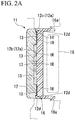
- FIG. 2A is a cross-sectional view taken along line 1A-1A of FIG. 1 .
- FIG. 2B is a cross-sectional view taken along line 1B-1B of FIG. 1 .
- the radar cover 11 of the present embodiment has an emblem 1E disposed at the center and a mesh-like outer design portion 1D disposed around the emblem 1E.
- a part of the emblem 1E and a part of the outer design portion 1D are shown in white, but the region shown in white is silver in the present embodiment.
- a region indicated by a dot pattern in the emblem 1E and the outer design portion 1D is black in the present embodiment.
- the lateral recess in the present invention includes those not parallel to the horizontal direction, such as the lateral recess 12g of the present embodiment shown in FIG. 1 , and only needs to have a horizontal direction component in an extension direction.
- the longitudinal recess 12f and the lateral recess 12g extend along the back surface of the transparent member 12, in other words, each extend in a direction orthogonal to the thickness direction.
- Such a paint layer 14 contains mica particles in the present embodiment.
- the mica particles reflect light incident on the paint layer 14 from the outside.
- the paint layer 14 looks bright, and the mica particles appear to shine intensely.
- the paint layer 14 looks dark, and the mica particles appear to shine weakly.
- Such an inner core 15 is fitted and disposed in the inner core housing recess 12b of the transparent member 12 such that the glittering film faces the inner wall surface of the inner core housing recess 12b.
- Such an inner core 15 is visually recognizable from the outside through the transparent member 12 and forms a region indicated by white of the emblem 1E shown in FIG. 1 .
- the appearance of the paint layer 14 formed on the upper connection surface 12g1 and the lower connection surface 12g2 can be made relatively dark, and the appearance of the paint layer 14 formed on the main design surface 12g6 can be made relatively bright. It is possible to further improve the stereoscopic effect of decoration.
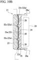
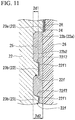
- FIG. 11 is a schematic enlarged cross-sectional view including a part of the inner core housing recess 22b.
- the transparent member 22 has a protrusion 22f protruding from a bottom portion 22b1 of the inner core housing recess 22b.
- the protrusion 22f is erected on the bottom 22b1 of the inner core housing recess 22b so as to protrude from a front side (left side in FIG. 11 ) of the transparent member 22 to a back side (right side in FIG. 11 ) thereof.
- a distal end surface 22f1 (end surface on a back side) of the protrusion 22f is formed in a flat surface, and is configured as a print layer forming surface (colored layer forming surface) on which the print layer 23 is formed.
- the paint layer 24 is a thin film layer formed by drying a silver paint capable of transmitting a radio wave used in the radar unit 2X and is silver as described above in the present embodiment.
- Such a support member 26 is formed of a synthetic resin such as an acrylonitrile/butadiene/styrene copolymer synthetic resin (ABS), an acrylonitrile/ethylene/styrene copolymer synthetic resin (AES), acrylonitrile/styrene/acrylate (ASA), polybutylene terephthalate (PBT), a colored PC, or polyethylene terephthalate (PET), or a composite resin thereof, and has a thickness of about 1.0 mm to 10 mm.
- ABS acrylonitrile/butadiene/styrene copolymer synthetic resin
- AES acrylonitrile/ethylene/styrene copolymer synthetic resin
- ASA acrylonitrile/styrene/acrylate
- PBT polybutylene terephthalate
- PET polyethylene terephthalate
- the radar cover 21 and the method for manufacturing the radar cover 21 according to the present embodiment as described above form the protrusion 22f protruding from the bottom 22b1 of the inner core housing recess 22b formed on a back side of the transparent member 22 and having the distal end surface 22f1 set as a print layer region on which the emblem print layer 23b is formed.
- the present invention is not limited thereto, and can be applied to a radar cover including a transparent member with a recess having a colored layer formed on an inner wall surface thereof and a method for manufacturing the radar cover.
Landscapes
- Engineering & Computer Science (AREA)
- Radar, Positioning & Navigation (AREA)
- Remote Sensing (AREA)
- Physics & Mathematics (AREA)
- Computer Networks & Wireless Communication (AREA)
- General Physics & Mathematics (AREA)
- Mechanical Engineering (AREA)
- Electromagnetism (AREA)
- Manufacturing & Machinery (AREA)
- Vehicle Waterproofing, Decoration, And Sanitation Devices (AREA)
- Radar Systems Or Details Thereof (AREA)
- Details Of Aerials (AREA)
Abstract
Description
- The present invention relates to a radar cover and a method for manufacturing the radar cover.
- The present application claims priority based on Japanese Patent Application No.
2016-239660 filed on December 9, 2016 2016-252958 filed on December 27, 2016 - In recent years, a radar unit for detecting an obstacle or the like around a vehicle using a radio wave such as a millimeter wave have been mounted on the vehicle. Generally, a radar unit is installed in a vehicle in a state in which the radar unit is covered with a radar cover to which a decoration such as an emblem has been applied. Such a radar unit transmits and receives a radio wave that has passed through the radar cover. Therefore, for example, as disclosed in Patent Documents 1 and 2, of course, it is necessary to form the radar cover so as to transmit a radio wave.
-
- [Patent Document 1] Japanese Unexamined Patent Application, First Publication No.
2016-141355 - [Patent Document 2] Japanese Unexamined Patent Application, First Publication No.
2016-80479 - By the way, a radar cover as disclosed in the above Patent Document 1 generally has, a transparent member disposed toward the outside of a vehicle, and a support member for supporting the transparent member from a back side. The transparent member and the support member are integrally formed by two-color molding of a resin. Such a radar cover has been enlarged in recent years. In addition to an emblem, various decorations may be applied to the radar cover. For example, by forming a curved recess on a back surface of the transparent member and applying a paint to an inner wall surface of the recess, a decoration visually recognizable from the outside of the transparent member may be applied.
- However, the decoration formed by applying a paint to the inner wall surface of the recess formed on a back surface of the transparent member is formed inside the radar cover. Therefore, due to restrictions on the thickness dimension of the radar cover or the like, a stereoscopic effect may be poorer than a decoration applied to the outside of the radar cover. Particularly, in recent years, a paint that changes the color thereof depending on a visual recognition direction has also been developed. However, merely by applying such a paint to the inner wall surface of the curved recess, only the color gradually and continuously changes, and it is difficult to enhance a stereoscopic effect.
- A radar cover as disclosed in the above Patent Document 2 generally has, a transparent member disposed toward the outside of a vehicle, and a support member for supporting the transparent member from a back side. The transparent member and the support member are integrally formed by two-color molding of a resin. Therefore, when a metal layer is formed between the transparent member and the support member, the metal layer can be visually recognized from the outside through the transparent member, and an emblem or a pattern can be formed by the metal layer.
- For example, as disclosed in Patent Document 2, in order to impart a stereoscopic effect such as an emblem, a recess may be formed on a back surface of the transparent member, and a metal layer may be disposed along an inner wall surface of the recess. In such a case, when a character or a pattern is superimposed on the metal layer when viewed from the front, it is conceivable to form a colored layer such as a print layer on a bottom surface of the recess. However, when the colored layer is formed on the bottom surface of the recess, a character or a pattern formed by the colored layer is planar, and this may impair a stereoscopic effect such as an emblem.
- The present invention has been achieved in view of the above circumstances, and a first object of the present invention is to improve a stereoscopic effect of a decoration formed inside a radar cover.
- In addition, a second object of the present invention is to impart a stereoscopic effect to a character or a pattern formed by a colored layer formed on an inner wall surface of a recess in a radar cover having the recess on a back surface of a transparent member.
- The present invention adopts the following configuration as a means for solving the above problems.
- A first aspect of the present invention is a radar cover disposed on a path of a radio wave of a radar unit for detecting a surrounding situation of a vehicle, the radar cover including a transparent member and a support member for supporting a back surface of the transparent member. The transparent member has an extension recess recessed toward a front surface side from the back surface, extending along the back surface, and having a paint layer formed on an inner wall surface thereof. The inner wall surface of the extension recess has, a first connection surface disposed on a first side in an orthogonal cross section with respect to an extension direction of the extension recess and connected to the back surface, a second connection surface disposed on a second side in the orthogonal cross section and connected to the back surface, and an intermediate surface connected to each of the first connection surface and the second connection surface and having a main design surface disposed such that a direction in which the main design surface is oriented is different from each of the first connection surface and the second connection surface.
- The radar cover according to the first aspect may have a lateral recess configured as the extension recess and extending in the horizontal direction, and the main design surface may be a flat surface inclined so as to extend downward toward a front surface side of the transparent member.
- In the first aspect, the main design surface may be wider than each of the first connection surface and the second connection surface.
- The radar cover according to the first aspect may have, an upper extension recess configured as the extension recess and disposed above the center of the transparent member in an up-down direction, and a lower extension recess configured as the extension recess and disposed below the center of the transparent member in the up-down direction.
- In the first aspect, the paint layer may be formed of a mica paint containing mica particles.
- In the first aspect, the intermediate surface may have, a first curved surface connected to the first connection surface, and a second curved surface connected to the second connection surface, and the main design surface may be disposed between the first curved surface and the second curved surface and formed in a flat surface.
- A second aspect of the present invention is a radar cover disposed on a path of a radio wave of a radar unit for detecting a surrounding situation of a vehicle, the radar cover including, a transparent member having a recess formed on a back surface thereof, a colored layer formed on an inner wall surface of the recess, and a support member for supporting the back surface of the transparent member. The transparent member has a protrusion protruding from a bottom of the recess and having the colored layer formed on a distal end surface thereof.
- In the second aspect, the distal end surface of the protrusion may be connected to a circumferential surface of the protrusion such that a connecting portion between the distal end surface and the circumferential surface is angular.
- In the second aspect, the distal end surface of the protrusion may be positioned at a front surface side of the transparent member compared to a back surface of the transparent member.
- A third aspect of the present invention is a method for manufacturing a radar cover disposed on a path of a radio wave of a radar unit for detecting a surrounding situation of a vehicle, in which the radar cover includes, a transparent member having a recess formed on a back surface thereof, a colored layer formed on an inner wall surface of the recess, and a support member for supporting the back surface of the transparent member, and the method includes, a transparent member forming step of forming the transparent member having a protrusion protruding from a bottom of the recess and having the colored layer formed on a distal end surface thereof, a coloring layer forming step of forming the colored layer on the distal end surface of the protrusion, and a support member forming step of forming the support member.
- In the transparent member forming step of the third aspect, the transparent member may be formed such that a connecting portion between the distal end surface of the protrusion and the circumferential surface of the protrusion is angular.
- In the transparent member forming step of the third aspect, the transparent member may be formed such that the distal end surface of the protrusion is positioned at a front surface side of the transparent member compared to the back surface of the transparent member.
- In the colored layer forming step of the third aspect, the colored layer may be formed on the distal end surface of the protrusion by transferring ink by a pad printing method.
- According to the first aspect of the present invention, the extension recess formed on the back surface of the transparent member has, a first connection surface disposed on a first side in an orthogonal cross section with respect to an extension direction of the extension recess and connected to the back surface, a second connection surface disposed on a second side in the orthogonal cross section with respect to the extension direction of the extension recess and connected to the back surface, and an intermediate surface connected to each of the first connection surface and the second connection surface, and the intermediate surface has a main design surface. Furthermore, the main design surface is disposed such that a direction in which the main design surface is oriented is different from each of the first connection surface and the second connection surface. Therefore, when the paint layer formed on the inner wall surface of the extension recess is viewed from a certain point outside a vehicle, a visual recognition angle with respect to the paint layer formed on the first connection surface and the second connection surface is different from a visual recognition angle with respect to the paint layer formed on the main design surface. As a result, the appearance of the paint layer formed on the first connection surface and the second connection surface is different from the appearance of the paint layer formed on the main design surface, when viewed by a viewer. Therefore, a stereoscopic effect of decoration formed by the paint layer increases. Therefore, according to the first aspect of the present invention, it is possible to improve a stereoscopic effect of decoration formed inside the radar cover.
- According to the second and third aspects of the present invention, the transparent member has a protrusion protruding from a bottom of a recess formed on a back surface thereof and having a colored layer formed on a distal end surface thereof. When such a colored layer formed on the distal end surface of the protrusion is visually recognized from the outside of the transparent member, surroundings of the colored layer are visually recognized to be brighter or darker than the colored layer, and a character or a pattern formed by the colored layer can have a stereoscopic appearance. Therefore, according to the second and third aspects of the present invention, it is possible to impart a stereoscopic effect to a character or a pattern formed by the colored layer formed on the inner wall surface of the recess in the radar cover having the recess on a back surface of the transparent member.
-
-
FIG. 1 is a front view schematically showing a radar cover according to a first embodiment of the present invention. -
FIG. 2A is a cross-sectional view taken alongline 1A-1A ofFIG. 1 . -
FIG. 2B is a cross-sectional view taken alongline 1B-1B ofFIG. 1 . -
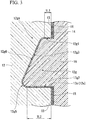
FIG. 3 is an enlarged cross-sectional view of a lateral recess included in the radar cover according to the first embodiment of the present invention. -
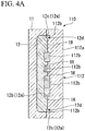
FIG. 4A is a schematic view showing a method for manufacturing the radar cover according to the first embodiment of the present invention. -
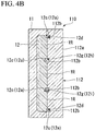
FIG. 4B is a schematic view showing the method for manufacturing the radar cover according to the first embodiment of the present invention. -
FIG. 5A is a schematic view showing the method for manufacturing the radar cover according to the first embodiment of the present invention. -
FIG. 5B is a schematic view showing the method for manufacturing the radar cover according to the first embodiment of the present invention. -
FIG. 6A is a schematic view showing the method for manufacturing the radar cover according to the first embodiment of the present invention. -
FIG. 6B is a schematic view showing the method for manufacturing the radar cover according to the first embodiment of the present invention. -
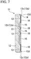
FIG. 7 is a schematic view showing the method for manufacturing the radar cover according to the first embodiment of the present invention. -
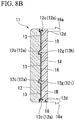
FIG. 8A is a schematic view showing the method for manufacturing the radar cover according to the first embodiment of the present invention. -
FIG. 8B is a schematic view showing the method for manufacturing the radar cover according to the first embodiment of the present invention. -
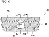
FIG. 9 is a front view schematically showing a radar cover according to a second embodiment of the present invention. -
FIG. 10A is a cross-sectional view taken alongline 2A-2A ofFIG. 9 . -
FIG. 10B is a cross-sectional view taken alongline 2B-2B ofFIG. 9 . -
FIG. 11 is a schematic enlarged cross-sectional view including a part of an inner core housing recess included in the radar cover according to the second embodiment of the present invention. -
FIG. 12A is a schematic view showing a method for manufacturing the radar cover according to the second embodiment of the present invention. -
FIG. 12B is a schematic view showing the method for manufacturing the radar cover according to the second embodiment of the present invention. -
FIG. 13A is a schematic view showing the method for manufacturing the radar cover according to the second embodiment of the present invention. -
FIG. 13B is a schematic view showing the method for manufacturing the radar cover according to the second embodiment of the present invention. -
FIG. 14 is a schematic view showing the method for manufacturing the radar cover according to the second embodiment of the present invention. -
FIG. 15A is a schematic view showing the method for manufacturing the radar cover according to the second embodiment of the present invention. -
FIG. 15B is a schematic view showing the method for manufacturing the radar cover according to the second embodiment of the present invention. -
FIG. 16 is a schematic view showing the method for manufacturing the radar cover according to the second embodiment of the present invention. -
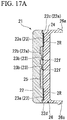
FIG. 17A is a schematic view showing the method for manufacturing the radar cover according to the second embodiment of the present invention. -
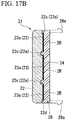
FIG. 17B is a schematic view showing the method for manufacturing the radar cover according to the second embodiment of the present invention. - Hereinafter, a radar cover according to a first embodiment of the present invention will be described with reference to the drawings. Incidentally, in the following drawings, in order to make each member have a recognizable size, the scale of each member is appropriately changed.
-
FIG. 1 is a front view schematically showing aradar cover 11 of the present embodiment.FIG. 2A is a cross-sectional view taken alongline 1A-1A ofFIG. 1 .FIG. 2B is a cross-sectional view taken alongline 1B-1B ofFIG. 1 . As shown inFIG. 1 , theradar cover 11 of the present embodiment has anemblem 1E disposed at the center and a mesh-likeouter design portion 1D disposed around theemblem 1E. Incidentally, inFIG. 1 , a part of theemblem 1E and a part of theouter design portion 1D are shown in white, but the region shown in white is silver in the present embodiment. A region indicated by a dot pattern in theemblem 1E and theouter design portion 1D is black in the present embodiment. - As shown in
FIGS. 2A and2B , theradar cover 11 of the present embodiment is disposed so as to cover aradar unit 1X for detecting a surrounding situation of a vehicle from a front side of the vehicle, and transmits a radio wave used in theradar unit 1X. Such aradar cover 11 of the present embodiment is disposed on a path of a radio wave of theradar unit 1X (in a region through which a radio wave emitted from theradar unit 1X is propagated), and includes atransparent member 12, aprint layer 13, apaint layer 14, aninner core 15, and asupport member 16 as shown inFIGS. 2A and2B . Hereinafter, the up-down direction on the sheet inFIGS. 1 ,2A , and2B is simply referred to as an up-down direction. The up-down direction is the same as the vertical direction when theradar cover 11 is installed in a vehicle. - The
transparent member 12 is formed of a transparent resin material and is disposed at the outermost side of a vehicle among constituent members of theradar cover 11. A front surface of thetransparent member 12 is formed in a smooth surface in order to enhance visibility of theemblem 1E and theouter design portion 1D as viewed from the outside of the vehicle. On a back surface of the transparent member 12 (a surface on a side of the support member 16), arecess 12a recessed toward a front surface side is formed. In theradar cover 11 of the present embodiment, thetransparent member 12 includes, as therecess 12a, an innercore housing recess 12b having theinner core 15 housed therein, and a paintedrecess 12c having thepaint layer 14 formed therein by application of a paint to the inner wall surface. A surface of thetransparent member 12 on a side of theradar unit 1X is referred to as a back surface, and the surface opposite thereto is referred to as a front surface (front). A side on which a back surface of thetransparent member 12 is located may be referred to as a back side, and a side on which a front surface thereof is located may be referred to as a front side. A direction in which the front surface and the back surface of thetransparent member 12 face each other, that is, a left-right direction on the sheet inFIGS. 2A and2B may be referred to as a thickness direction. - The inner
core housing recess 12b is formed in a circular shape when viewed from the front and is disposed at the center of theradar cover 11 on which theemblem 1E is disposed. A circular outer edge of the innercore housing recess 12b is disposed avoiding the character "F" shown inFIG. 1 , and the character "F" is located inside the circular outer edge. Such an innercore housing recess 12b houses theinner core 15 in a state in which theinner core 15 is in contact with the inner wall surface. - The painted
recess 12c has a frame-like portion 12d formed in a frame shape in an outer edge portion of theradar cover 11 and a mesh-like portion 12e formed in a mesh shape inside the frame-like portion 12d, when viewed from the front. In such a paintedrecess 12c, thepaint layer 14 is disposed so as to cover the inner wall surface. A part of thesupport member 16 enters the paintedrecess 12c, and thepaint layer 14 is covered from the back side by thesupport member 16. - As shown in
FIG. 1 , in the present embodiment, the mesh-like portion 12e has a shape in which a plurality of substantially regular hexagons is disposed in a close contact state, and has, alongitudinal recess 12f (extension recess) extending parallel to the vertical direction, and alateral recess 12g (extension recess) extending in the horizontal direction. That is, thelongitudinal recess 12f and thelateral recess 12g are configured as extension recesses of the present invention. Incidentally, as shown inFIG. 1 , thelateral recess 12g in the present embodiment extends in a direction not parallel to the horizontal direction. The lateral recess in the present invention includes those not parallel to the horizontal direction, such as thelateral recess 12g of the present embodiment shown inFIG. 1 , and only needs to have a horizontal direction component in an extension direction. Thelongitudinal recess 12f and thelateral recess 12g extend along the back surface of thetransparent member 12, in other words, each extend in a direction orthogonal to the thickness direction. - In the present embodiment, the
lateral recess 12g is formed both above and below the center of thetransparent member 12 in the up-down direction. Hereinafter, thelateral recess 12g disposed above the center of thetransparent member 12 in the up-down direction is referred to as an upperlateral recess 12h (upper extension recess), and thelateral recess 12g disposed below the center of thetransparent member 12 in the up-down direction is referred to as lowerlateral recess 12i (lower extension recess). That is, each of the upperlateral recess 12h and the lowerlateral recess 12i is configured as an extension recess of the present invention. - In the present embodiment, a region in which the
recess 12a is not formed on a surface (back surface) of thetransparent member 12 on a side of thesupport member 16 is configured as a printlayer forming region 1R where theprint layer 13 is formed. The printlayer forming region 1R is formed in a flat surface and is covered from a back side of thetransparent member 12 by theprint layer 13. -
FIG. 3 is an enlarged cross-sectional view of thelateral recess 12g. As shown inFIG. 3 , in theradar cover 11 of the present embodiment, the inner wall surface of thelateral recess 12g has, an upper connection surface 12g1 (first connection surface), a lower connection surface 12g2 (second connection surface), and an intermediate surface 12g3. The upper connection surface 12g1 forms an upper portion of thelateral recess 12g and is bent and connected to the back surface of the transparent member 12 (printlayer forming region 1R). That is, a connecting portion between the upper connection surface 12g1 and the printlayer forming region 1R is angular backward and obliquely downward. The lower connection surface 12g2 forms a lower portion of thelateral recess 12g and is bent and connected to the back surface of the transparent member 12 (printlayer forming region 1R). That is, a connecting portion between the lower connection surface 12g2 and the printlayer forming region 1R is angular backward and obliquely upward. That is, in the present embodiment, the inner wall surface of thelateral recess 12g has, the upper connection surface 12g1 disposed on one side (first side) of an orthogonal cross section with respect to an extension direction of thelateral recess 12g, and the lower connection surface 12g2 disposed on the other side (second side) of the orthogonal cross section with respect to the extension direction of thelateral recess 12g. The upper connection surface 12g1 and the lower connection surface 12g2 are bent at an angle of approximately 90° and connected to the back surface of the transparent member 12 (printlayer forming region 1R). Note that the angle formed by each of the upper connection surface 12g1 and the lower connection surface 12g2 and the back surface of the transparent member 12 (printlayer forming region 1R) may be about 93° in consideration of a draft during injection molding. That is, the angle formed by each of the upper connection surface 12g1 and the lower connection surface 12g2 and the back surface of the transparent member 12 (the printlayer forming region 1R) may be an obtuse angle. - The intermediate surface 12g3 connects the upper connection surface 12g1 to the lower connection surface 12g2, and has, an upper curved surface 12g4 (first curved surface) smoothly connected to the upper connection surface 12g1 without being bent, a lower curved surface 12g5 (second curved surface) smoothly connected to the lower connection surface 12g2 without being bent, and a main design surface 12g6 disposed between the upper curved surface 12g4 and the lower curved surface 12g5. The main design surface 12g6 is a region mainly forming the shape of a mesh-like pattern of the
outer design portion 1D when theradar cover 11 of the present embodiment is visually recognized from the outside. The main design surface 12g6 is formed in a flat surface such that when an orthogonal axis perpendicular to the main design surface 12g6 is virtually considered, the orthogonal axis goes upward toward the front of a vehicle. That is, the main design surface 12g6 is a flat surface inclined such that a direction perpendicular to the main design surface 12g6 goes upward toward a front surface side of thetransparent member 12. In other words, the main design surface 12g6 is a flat surface inclined so as to extend downward toward the front surface side of thetransparent member 12. In the present embodiment, as shown inFIG. 3 , the main design surface 12g6 is disposed in such a posture that the main design surface 12g6 has a different angle from the upper connection surface 12g1 and the lower connection surface 12g2 with respect to the vertical axis, and has a larger area than the upper connection surface 12g1 and the lower connection surface 12g2. In other words, the main design surface 12g6 is disposed such that a direction in which the main design surface 12g6 is oriented (a direction orthogonal to the main design surface 12g6) is different from each of the upper connection surface 12g1 and the lower connection surface 12g2. - Incidentally, similarly to the
lateral recess 12g, the inner wall surface of thelongitudinal recess 12f also has, a first connection surface disposed on one side in an orthogonal cross section with respect to an extension direction of thelongitudinal recess 12f and connected to a back surface of thetransparent member 12, a second connection surface disposed on the other side in the orthogonal cross section with respect to the extension direction of thelongitudinal recess 12f and connected to the back surface of thetransparent member 12, and an intermediate surface connected to each of the first connection surface and the second connection surface and having a main design surface set at a different angle from each of the first connection surface and the second connection surface. In other words, the main design surface is disposed such that a direction in which the main design surface is oriented is different from each of the first connection surface and the second connection surface. In addition to the main design surface, the intermediate surface has, a first curved surface interposed between the main design surface and the first connection surface, and a second curved surface interposed between the main design surface and the second connection surface. - Such a
transparent member 12 is formed of a transparent synthetic resin such as colorless polycarbonate (PC) or a polymethyl methacrylate resin (PMMA), for example, and has a thickness of about 1.5 mm to 10 mm. A front surface of thetransparent member 12 is subjected to a hard coat treatment for preventing scratches or a clear coat treatment with a urethane-based paint as necessary. Note that a transparent synthetic resin having scratch resistance does not need to be subjected to the scratch preventing treatment. - With reference to
FIGS. 2A and2B again, theprint layer 13 is a thin film layer printed on the printlayer forming region 1R of thetransparent member 12 and is black as described above in the present embodiment. Theprint layer 13 is formed by transferring black ink onto the printlayer forming region 1R and drying the ink. Theprint layer 13 can be formed by putting a black resin ink capable of transmitting a radio wave used in theradar unit 1X on the printlayer forming region 1R, for example, by a silk printing method and drying the ink naturally. Such aprint layer 13 is visually recognizable from the outside through thetransparent member 12 and forms a region indicated by the dot pattern shown inFIG. 1 . - The
paint layer 14 is a thin film layer formed by drying a silver paint capable of transmitting a radio wave used in theradar unit 1X and is silver as described above in the present embodiment. - As shown in
FIGS. 2A and2B , thepaint layer 14 is disposed on the entire back surface of thetransparent member 12 on which theprint layer 13 is formed except for a region where theemblem 1E is formed. That is, thepaint layer 14 covers a surface of theprint layer 13 on a side of thesupport member 16 except for the region where theemblem 1E is formed. Thepaint layer 14 can be formed, for example, by applying a paint containing a pearl pigment and drying the paint naturally. Such apaint layer 14 is visually recognizable from the outside through thetransparent member 12 and forms a region indicated by white of theouter design portion 1D shown inFIG. 1 in the paintedrecess 12c. - Such a
paint layer 14 contains mica particles in the present embodiment. The mica particles reflect light incident on thepaint layer 14 from the outside. When such apaint layer 14 is visually recognized from a direction perpendicular to thepaint layer 14, thepaint layer 14 looks bright, and the mica particles appear to shine intensely. Meanwhile, when thepaint layer 14 is visually recognized from a direction largely deviated from the direction perpendicular to thepaint layer 14, thepaint layer 14 looks dark, and the mica particles appear to shine weakly. - The
inner core 15 has, a base formed of a resin capable of transmitting a radio wave used in the radar unit IX, and a glittering film formed so as to cover a front surface of the base. Examples of the glittering film include an indium film which is a discontinuous film having many gaps capable of transmitting a radio wave formed therein. Such an indium film can be formed, for example, by a vacuum vapor deposition method or a sputtering method. Note that theinner core 15 may have a transparent top coat layer covering a front surface of the glittering film or an undercoat layer covering a back surface of the glittering film. Such aninner core 15 is fitted and disposed in the innercore housing recess 12b of thetransparent member 12 such that the glittering film faces the inner wall surface of the innercore housing recess 12b. Such aninner core 15 is visually recognizable from the outside through thetransparent member 12 and forms a region indicated by white of theemblem 1E shown inFIG. 1 . - The
support member 16 is a part bonded to the back surface of thetransparent member 12 and supporting thetransparent member 12, and is formed of a black resin material. Thesupport member 16 has an engagingportion 16a protruding toward a side of an engine room (back side) of a vehicle. The engagingportion 16a has a claw-shaped distal end portion, and the distal end portion is engaged, for example, with a radiator grill main body of a vehicle. Such asupport member 16 is formed of a synthetic resin such as an acrylonitrile/butadiene/styrene copolymer synthetic resin (ABS), an acrylonitrile/ethylene/styrene copolymer synthetic resin (AES), acrylonitrile/styrene/acrylate (ASA), polybutylene terephthalate (PBT), a colored PC, or polyethylene terephthalate (PET), or a composite resin thereof, and has a thickness of about 1.0 mm to 10 mm. - Subsequently, a method for manufacturing the
radar cover 11 of the present embodiment will be described with reference toFIGS. 4A to 8B . - First, as shown in
FIGS. 4A and4B , thetransparent member 12 is formed. Note thatFIG. 4A is a cross-sectional view at the same position asFIG. 2A , andFIG. 4B is a cross-sectional view at the same position asFIG. 2B . Here, thetransparent member 12 is formed by injection molding using adie 110. Thedie 110 has a fixed side cavity die 111 and a moving side core die 112. Furthermore, in the present embodiment, the core die 112 has, abase 112a forming the printlayer forming region 1R, and anest 112b for forming therecess 12a. Thenest 112b is formed separately from thebase 112a of the core die 112 and protrudes from a front surface of thebase 112a toward a side of the cavity die 111 in a state of being fixed to thebase 112a. By disposing thenest 112b in the core die 112 as described above, a front surface of thebase 112a and a front surface of thenest 112b can be bent and connected to each other to form thetransparent member 12 in which the printlayer forming region 1R and the inner wall surface of therecess 12a are bent and connected to each other. - Subsequently, as shown in
FIGS. 5A and 5B , theprint layer 13 is formed. Note thatFIG. 5A is a cross-sectional view at the same position asFIG. 2A , andFIG. 5B is a cross-sectional view at the same position asFIG. 2B . Here, theprint layer 13 is formed by transferring ink onto the printlayer forming region 1R which is a region except for therecess 12a of thetransparent member 12 by a printing method such as a silk printing method and drying the ink. At this time, in theradar cover 11 of the present embodiment, the printlayer forming region 1R and the inner wall surface of therecess 12a are bent and connected to each other. Therefore, the ink transferred onto the printlayer forming region 1R has more difficulty in moving to the inner wall surface of therecess 12a than a case where the printlayer forming region 1R and the inner wall surface of therecess 12a are connected with a smooth curved surface. According to such a method for manufacturing theradar cover 11 of the present embodiment, it is possible to prevent unintentional movement of an end portion of theprint layer 13. - Subsequently, as shown in
FIGS. 6A and 6B , thepaint layer 14 is formed. Note thatFIG. 6A is a cross-sectional view at the same position asFIG. 2A , andFIG. 6B is a cross-sectional view at the same position asFIG. 2B . Here, in a state in which aregion 1M where theemblem 1E shown inFIG. 6A is formed is masked, a silver mica paint is sprayed, for example, on a back side of thetransparent member 12 on which theprint layer 13 is formed, and the mica paint is dried to form thepaint layer 14. In thepaint layer 14 thus formed, thepaint layer 14 covering theprint layer 13 and directly adhering to the inner wall surface of the entire paintedrecess 12c is formed except for the region where theemblem 1E is formed. - Subsequently, as shown in
FIG. 7 , theinner core 15 is housed in the innercore housing recess 12b. Note thatFIG. 7 is a cross-sectional view at the same position asFIG. 2A . Here, theinner core 15 formed in parallel to formation of the above-describedtransparent member 12,print layer 13, orpaint layer 14 is housed in the innercore housing recess 12b. Theinner core 15 is formed by forming a glittering discontinuous metal film such as an indium layer on a base formed by injection molding in advance by a vacuum vapor deposition method, a sputtering method, or the like. Note that a topcoat layer or an undercoat layer is formed as necessary in theinner core 15. Such aninner core 15 is housed in the innercore housing recess 12b with the glittering discontinuous metal film facing a side of the inner wall surface of the innercore housing recess 12b. - Subsequently, as shown in
FIGS. 8A and8B , thesupport member 16 is formed. Note thatFIG. 8A is a cross-sectional view at the same position asFIG. 2A , andFIG. 8B is a cross-sectional view at the same position asFIG. 2B . Here, thetransparent member 12 having theinner core 15 disposed in the innercore housing recess 12b is disposed inside a die for injection molding, and insert molding for emitting a molten resin to the back side of thetransparent member 12 is performed to form thesupport member 16. Such asupport member 16 is welded to thetransparent member 12 by heat during insert molding and disposed so as to cover theinner core 15. As a result, theinner core 15 is fixed to thetransparent member 12. Note that thetransparent member 12 and thesupport member 16 may be each individually formed by injection molding or the like, and then thetransparent member 12 and thesupport member 16 may be coupled together using an adhesive, a fastening member, or the like. Even in this case, thesupport member 16 supports thetransparent member 12. - According to the
radar cover 11 of the present embodiment as described above, thelateral recess 12g formed on the back surface of thetransparent member 12 forms an upper portion of thelateral recess 12g and has, the upper connection surface 12g1 connected to the back surface of thetransparent member 12, the lower connection surface 12g2 forming a lower portion of thelateral recess 12g and connected to the back surface of thetransparent member 12, and the intermediate surface 12g3 connected to the upper connection surface 12g1 and the lower connection surface 12g2, and the intermediate surface 12g3 has the main design surface 12g6. Furthermore, the main design surface 12g6 is set at a different angle from the upper connection surface 12g1 and the lower connection surface 12g2. That is, the main design surface 12g6 is disposed such that a direction in which the main design surface 12g6 is oriented is different from each of the upper connection surface 12g1 and the lower connection surface 12g2. Therefore, when thepaint layer 14 formed on the inner wall surface of thelateral recess 12g is viewed from a certain point outside a vehicle, a visual recognition angle with respect to thepaint layer 14 formed on the upper connection surface 12g1 and the lower connection surface 12g2 is different from a visual recognition angle with respect to thepaint layer 14 formed on the main design surface 12g6. As a result, thepaint layer 14, the appearance of thepaint layer 14 formed on the upper connection surface 12g1 and the lower connection surface 12g2 is different from the appearance of thepaint layer 14 formed on the main design surface 12g6, when viewed by a viewer. Therefore, a stereoscopic effect of decoration formed by thepaint layer 14 increases. Therefore, according to theradar cover 11 of the present embodiment, it is possible to improve a stereoscopic effect of decoration formed inside theradar cover 11. - In the
radar cover 11 of the present embodiment, similarly to thelateral recess 12g, thelongitudinal recess 12f also has, a first connection surface disposed on one side in an orthogonal cross section with respect to an extension direction of thelongitudinal recess 12f and connected to a back surface of thetransparent member 12, a second connection surface disposed on the other side in the orthogonal cross section with respect to the extension direction of thelongitudinal recess 12f and connected to the back surface of thetransparent member 12, and an intermediate surface connected to each of the first connection surface and the second connection surface and having a main design surface set at a different angle from each of the first connection surface and the second connection surface. In addition to the main design surface, the intermediate surface has, a first curved surface interposed between the main design surface and the first connection surface, and a second curved surface interposed between the main design surface and the second connection surface. Therefore, also in thelongitudinal recess 12f, it is possible to increase the stereoscopic effect of decoration formed by thepaint layer 14. - In the
radar cover 11 of the present embodiment, the main design surface 12g6 is formed in a flat surface inclined such that a direction perpendicular to the main design surface 12g6 goes upward toward a front surface side of thetransparent member 12. In other words, the main design surface 12g6 is a flat surface inclined so as to extend downward toward the front surface side of thetransparent member 12. In many cases, a viewer who visually recognizes theradar cover 11 from the outside looks down on theradar cover 11 obliquely from above. Therefore, by inclining the main design surface 12g6 so as to face upward, the main design surface 12g6 can directly face the viewer, and the entireouter design portion 1D can be recognized brightly. Therefore, the appearance of thepaint layer 14 formed on the upper connection surface 12g1 and the lower connection surface 12g2 can be made relatively dark, and the appearance of thepaint layer 14 formed on the main design surface 12g6 can be made relatively bright. It is possible to further improve the stereoscopic effect of decoration. - In the
radar cover 11 of the present embodiment, the main design surface 12g6 is set so as to be wider than the upper connection surface 12g1 and the lower connection surface 12g2. This makes it possible to make thepaint layer 14 formed on the main design surface 12g6 more conspicuous than thepaint layer 14 formed on the upper connection surface 12g1 and the lower connection surface 12g2. Furthermore, as described above, when the main design surface 12g6 is inclined so as to face upward, a region corresponding to the main design surface 12g6 visually recognized to be bright is wider than a region corresponding to the upper connection surface 12g1 and the lower connection surface 12g2 visually recognized to be dark. Therefore, it is possible to improve decorative design. - The
radar cover 11 of the present embodiment has, an upperlateral recess 12h which is thelateral recess 12g disposed above the center of thetransparent member 12 in the up-down direction, and a lowerlateral recess 12i which is thelateral recess 12g disposed below the center of thetransparent member 12 in the up-down direction. Therefore, in theradar cover 11 of the present embodiment, it is possible to visually recognize both the decoration formed in an upper portion in the up-down direction and the decoration formed in a lower portion in the up-down direction stereoscopically. In particular, in both the upperlateral recess 12h and the lowerlateral recess 12i, when the main design surface 12g6 is inclined upward and the main design surface 12g6 is set to be wider than the upper connection surface 12g1 and the lower connection surface 12g2, it is possible to visually recognize the entireouter design portion 1D stereoscopically and brightly. - In the
radar cover 11 of the present embodiment, thepaint layer 14 contains mica particles. Therefore, it is possible to make a region that looks bright more conspicuous, and it is possible to further improve a stereoscopic effect of decoration. - In the
radar cover 11 of the present embodiment, the intermediate surface 12g3 has, the upper curved surface 12g4 (first curved surface) smoothly connected to the upper connection surface 12g1 without being bent, the lower curved surface 12g5 (second curved surface) smoothly connected to the lower connection surface 12g2 without being bent, and the main design surface 12g6 disposed between the upper curved surface 12g4 and the lower curved surface 12g5. Therefore, it is possible to change the appearance of the main design surface 12g6 and the appearance of the upper curved surface 12g4 and the lower curved surface 12g5, and it is possible to make the outline of the main design surface 12g6 conspicuous. For example, when the main design surface 12g6 looks dark, it is possible to make the upper curved surface 12g4 and the lower curved surface 12g5 look bright, and the outline of the main design surface 12g6 is conspicuous. Similarly, also in thelongitudinal recess 12f, the intermediate surface has the curved surface (the first curved surface and the second curved surface). Therefore, the outline of the main design surface can be conspicuous. Therefore, according to theradar cover 11 of the present embodiment, it is possible to further improve a stereoscopic effect of decoration. That is, as shown inFIG. 3 , if the length dimension of the upper connection surface 12g1 to the back surface of thetransparent member 12 is represented by 1L1 and the length dimension of the lower connection surface 12g2 to the back surface of thetransparent member 12 is represented by 1L2, in a state in which 1L1 is the same or substantially the same as 1L2, the main design surface 12g6 is visually recognized to be darkest, and the upper curved surface 12g4 and the lower curved surface 12g5 located above and below the main design surface 12g6 are visually recognized to be bright. - Meanwhile, as shown in
FIG. 3 , by setting 1L1 to half or approximately half of 1L2, when a viewpoint is above theradar cover 11 in a state in which theradar cover 11 is attached to a vehicle, the main design surface 12g6 is visually recognized to be brightest, and the three surfaces including the upper curved surface 12g4 and the lower curved surface 12g5 have almost the same brightness and recognized as a wide surface. When the viewpoint is gradually lowered from this state and reaches a state of being substantially horizontal with theradar cover 11, only the main design surface 12g6 is dark, and the main design surface 12g6 is visually recognized as if the main design surface 12g6 is edged by the upper curved surface 12g4 and the lower curved surface 12g5 visually recognized to be bright. In this way, by combining the flat portion and the curved portion even though these portions form onepaint layer 14, different designs can appear depending on the position of the viewpoint. - Hitherto, the preferred embodiment of the present invention has been described with reference to the attached drawings, but the present invention is not limited to the above embodiment. The shapes, the combinations, and the like of the respective constituent members described in the above embodiment are merely examples, and various modifications can be made based on design requirement or the like without departing from the gist of the present invention.
- For example, in the above embodiment, the configuration in which the
lateral recess 12g is formed in a part of the mesh-like portion 12e has been described. However, the present invention is not limited thereto, and can adopt a configuration having a lateral recess with another shape. For example, it is also possible to adopt a configuration having a lateral recess extending parallel to the horizontal direction. - In the above embodiment, the configuration in which the
inner core 15 is housed in the innercore housing recess 12b of thetransparent member 12 and theinner core 15 is sandwiched between thetransparent member 12 and thesupport member 16 to form theemblem 1E has been described. However, the present invention is not limited thereto. For example, the present invention can be applied to a radar cover having a configuration in which a glittering discontinuous film is directly formed on a front surface of thetransparent member 12 or thesupport member 16 and theinner core 15 is omitted, and a method for manufacturing the radar cover. - In the present embodiment, the extension recess (the
longitudinal recess 12f and thelateral recess 12g) has, a first connection surface disposed on one side in an orthogonal cross section with respect to an extension direction and connected to a back surface of thetransparent member 12, a second connection surface disposed on the other side in the orthogonal cross section with respect to the extension direction of the extension recess and connected to the back surface of thetransparent member 12, and an intermediate surface connected to each of the first connection surface and the second connection surface and having a main design surface set at a different angle from each of the first connection surface and the second connection surface. - However, if the intermediate surface has, a first curved surface connected to the first connection surface without being bent, a second curved surface connected to the second connection surface without being bent, and a main design surface disposed between the first curved surface and the second curved surface and formed in a flat surface, the outline of the main design surface can be conspicuous. Therefore, even in such an extension recess having only an intermediate surface, it is possible to improve a stereoscopic effect of decoration by making the outline of the main design surface conspicuous.
- Hereinafter, a radar cover and a method for manufacturing the radar cover according to a second embodiment of the present invention will be described with reference to the drawings. Incidentally, in the following drawings, in order to make each member have a recognizable size, the scale of each member is appropriately changed.
-
FIG. 9 is a front view schematically showing aradar cover 21 of the present embodiment.FIG. 10A is a cross-sectional view taken alongline 2A-2A ofFIG. 9 .FIG. 10B is a cross-sectional view taken alongline 2B-2B ofFIG. 9 . As shown inFIG. 9 , theradar cover 21 of the present embodiment has, anemblem 2E disposed at the center, and a mesh-likeouter design portion 2D disposed around theemblem 2E. Incidentally, inFIG. 9 , a part of theemblem 2E and a part of theouter design portion 2D are shown in white, but the region shown in white is silver in the present embodiment. A region indicated by a dot pattern in theemblem 2E and theouter design portion 2D is black in the present embodiment. - As shown in
FIGS. 10A and10B , theradar cover 21 of the present embodiment is disposed so as to cover aradar unit 2X for detecting a surrounding situation of a vehicle from a front side of the vehicle, and transmits a radio wave used in theradar unit 2X. Such aradar cover 21 of the present embodiment is disposed on a traveling path of a radio wave of theradar unit 2X (in a region through which a radio wave emitted from theradar unit 2X is propagated), and includes, atransparent member 22, a print layer 23 (colored layer), apaint layer 24, aninner core 25, and asupport member 26 as shown inFIGS. 10A and10B . Hereinafter, the up-down direction on the sheet inFIGS. 9 ,10A , and10B is simply referred to as an up-down direction. The up-down direction is the same as the vertical direction when theradar cover 21 is installed in a vehicle. - The
transparent member 22 is formed of a transparent resin material and is disposed at the outermost side of a vehicle among constituent members of theradar cover 21. A front surface of thetransparent member 22 is formed in a smooth surface in order to enhance visibility of theemblem 2E and theouter design portion 2D as viewed from the outside of the vehicle. On a back surface of the transparent member 22 (a surface on a side of the support member 26), arecess 22a is formed. In theradar cover 21 of the present embodiment, thetransparent member 22 includes, as therecess 22a, an innercore housing recess 22b having theinner core 25 housed therein, and a paintedrecess 22c having thepaint layer 24 formed therein by application of a paint to the inner wall surface. A surface of thetransparent member 22 on a side of theradar unit 2X is referred to as a back surface, and the surface opposite thereto is referred to as a front surface (front). A side on which a back surface of thetransparent member 22 is located may be referred to as a back side, and a side on which a front surface thereof is located may be referred to as a front side. A direction in which the front surface and the back surface of thetransparent member 22 face each other, that is, a left-right direction on the sheet inFIGS. 10A and10B may be referred to as a thickness direction. - The inner
core housing recess 22b is formed in a circular shape along the outer shape of theemblem 2E when viewed from the front and is formed at the center of theradar cover 21 on which theemblem 2E is disposed. - Such an inner
core housing recess 22b houses theinner core 25 in a state in which theinner core 25 is in contact with the inner wall surface. - The painted
recess 22c has, a frame-like portion 22d formed in a frame shape on an outer edge portion of theradar cover 21, and a mesh-like portion 22e formed in a mesh shape inside the frame-like portion 22d, when viewed from the front. In such a paintedrecess 22c, thepaint layer 24 is disposed so as to cover the inner wall surface. A part of thesupport member 26 enters the paintedrecess 22c, and thepaint layer 24 is covered from the back side by thesupport member 26. - In the present embodiment, a region in which the
recess 22a is not formed on a surface (back surface) of thetransparent member 22 on a side of thesupport member 26 is configured as a printlayer forming region 2R where theprint layer 23 is formed. The printlayer forming region 2R is formed in a flat surface and is covered from a back side of thetransparent member 22 by theprint layer 23. -
FIG. 11 is a schematic enlarged cross-sectional view including a part of the innercore housing recess 22b. As shown inFIG. 11 , thetransparent member 22 has aprotrusion 22f protruding from a bottom portion 22b1 of the innercore housing recess 22b. Theprotrusion 22f is erected on the bottom 22b1 of the innercore housing recess 22b so as to protrude from a front side (left side inFIG. 11 ) of thetransparent member 22 to a back side (right side inFIG. 11 ) thereof. A distal end surface 22f1 (end surface on a back side) of theprotrusion 22f is formed in a flat surface, and is configured as a print layer forming surface (colored layer forming surface) on which theprint layer 23 is formed. - The distal end surface 22f1 of the
protrusion 22f is positioned at the front side of thetransparent member 22 compared to the printlayer forming region 2R which is the back surface of thetransparent member 22. That is, a protrusion dimension 2d1 of the bottom 22b1 of the innercore housing recess 22b of theprotrusion 22f is set to be smaller than a depth dimension 2d2 of the innercore housing recess 22b. - The distal end surface 22f1 of the
protrusion 22f is bent at an angle of approximately 90° and connected to a circumferential surface 22f2 of theprotrusion 22f. The circumferential surface 22f2 is a surface substantially facing a direction orthogonal to a thickness direction. That is, a boundary portion between the distal end surface 22f1 of theprotrusion 22f and the circumferential surface 22f2 thereof is configured as a so-called pin angle. In other words, the distal end surface 22f1 of theprotrusion 22f is connected to the circumferential surface 22f2 of theprotrusion 22f such that a connecting portion between the distal end surface 22f1 and the circumferential surface 22f2 is angular. Note that the angle formed by the distal end surface 22f1 of theprotrusion 22f and the circumferential surface 22f2 thereof is preferably 90°, but may be about 93° in consideration of a draft during injection molding. That is, the angle formed by the distal end surface 22f1 of theprotrusion 22f and the circumferential surface 22f2 thereof may be an obtuse angle. - Such a
transparent member 22 is formed of a transparent synthetic resin such as colorless polycarbonate (PC) or a polymethyl methacrylate resin (PMMA), for example, and has a thickness of about 1.5 mm to 10 mm. A front surface of thetransparent member 22 is subjected to a hard coat treatment for preventing scratches or a clear coat treatment with a urethane-based paint as necessary. Note that a transparent synthetic resin having scratch resistance does not need to be subjected to the scratch preventing treatment. - The
print layer 23 is a thin film layer printed on the printlayer forming region 2R of thetransparent member 22 and the distal end surface 22f1 of theprotrusion 22f, and is black as described above in the present embodiment. Theprint layer 23 is formed by transferring a black ink onto the printlayer forming region 2R or the distal end surface 22f1 of theprotrusion 22f and drying the ink. Theprint layer 23 formed on the printlayer forming region 2R (back surface) of the transparent member 22 (hereinafter referred to as anouter print layer 23a) can be formed by putting a black resin ink capable of transmitting a radio wave used in theradar unit 2X on the printlayer forming region 2R, for example, by a silk printing method and drying the ink naturally. Theprint layer 23 formed on the distal end surface 22f1 of theprotrusion 22f (hereinafter referred to as anemblem print layer 23b (colored layer)) can be formed by putting a black resin ink capable of transmitting a radio wave used in theradar unit 2X on the distal end surface 22f1 of theprotrusion 22f, for example, by a pad printing method and drying the ink naturally. - The
outer print layer 23a and theemblem print layer 23b are visually recognizable from the outside through thetransparent member 22 and form a region indicated by the dot pattern shown inFIG. 9 . For example, theouter print layer 23a forms a portion excluding the mesh-like pattern of theouter design portion 2D. Theemblem print layer 23b forms a character portion of "F" of theemblem 2E. - The
paint layer 24 is a thin film layer formed by drying a silver paint capable of transmitting a radio wave used in theradar unit 2X and is silver as described above in the present embodiment. - As shown in
FIGS. 10A and10B , thepaint layer 24 is disposed on the entire back surface of thetransparent member 22 on which theprint layer 23 is formed except for a region where theemblem 2E is formed. That is, thepaint layer 24 covers a surface of theprint layer 23 on a side of thesupport member 26 except for the region where theemblem 2E is formed. Thepaint layer 24 can be formed, for example, by applying a paint containing a pearl pigment and drying the paint naturally. Such apaint layer 24 is visually recognizable from the outside through thetransparent member 22 and forms a region indicated by white of theouter design portion 2D shown inFIG. 9 in the paintedrecess 22c. - The
inner core 25 has, a base formed of a resin capable of transmitting a radio wave used in theradar unit 2X, and a glittering film formed so as to cover a front surface of the base. Examples of the glittering film include an indium film formed in a discontinuous film having many gaps capable of transmitting a radio wave. Such an indium film can be formed by, for example, a vacuum vapor deposition method or a sputtering method. Note that theinner core 25 may have a transparent top coat layer covering a front surface of the glittering film or an undercoat layer covering a back surface of the glittering film. Theinner core 25 has a groove corresponding to theprotrusion 22f of thetransparent member 22. Such aninner core 25 is fitted and disposed in the innercore housing recess 22b of thetransparent member 22 such that the glittering film faces the inner wall surface of the innercore housing recess 22b and furthermore theprotrusion 22f is fitted into the groove. Such aninner core 25 is visually recognizable from the outside through thetransparent member 22 and forms a region indicated by white of theemblem 2E shown inFIG. 9 . - The
support member 26 is a part bonded to the back surface of thetransparent member 22 and supporting thetransparent member 22, and is formed of a black resin material. Thesupport member 26 has an engagingportion 26a protruding toward a side of an engine room of a vehicle. The engagingportion 26a has a claw-shaped distal end portion, and the distal end portion is engaged, for example, with a radiator grill main body. Such asupport member 26 is formed of a synthetic resin such as an acrylonitrile/butadiene/styrene copolymer synthetic resin (ABS), an acrylonitrile/ethylene/styrene copolymer synthetic resin (AES), acrylonitrile/styrene/acrylate (ASA), polybutylene terephthalate (PBT), a colored PC, or polyethylene terephthalate (PET), or a composite resin thereof, and has a thickness of about 1.0 mm to 10 mm. - Subsequently, a method for manufacturing the
radar cover 21 of the present embodiment will be described with reference toFIGS. 12A to 17B . - First, as shown in
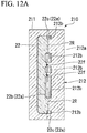
FIGS. 12A and12B , thetransparent member 22 is formed. Note thatFIG. 12A is a cross-sectional view at the same position asFIG. 10A , andFIG. 12B is a cross-sectional view at the same position asFIG. 10B . Here, thetransparent member 22 is formed by injection molding using adie 210. Thedie 210 has a fixed side cavity die 211 and a moving side core die 212. Furthermore, in the present embodiment, the core die 212 has, abase 212a forming the printlayer forming region 2R, and anest 212b for forming therecess 22a. Thenest 212b is formed separately from thebase 212a of the core die 212 and protrudes from a front surface of thebase 212a toward a side of the cavity die 211 in a state of being fixed to thebase 212a. By disposing thenest 212b in the core die 212 as described above, a front surface of thebase 212a and a front surface of thenest 212b can be bent and connected to each other to form thetransparent member 22 in which the distal end surface 22f1 of theprotrusion 22f and the circumferential surface 22f2 thereof are bent and connected to each other. That is, it is possible to form thetransparent member 22 in which a connecting portion between the distal end surface 22f1 of theprotrusion 22f and the circumferential surface 22f2 thereof is angular. Such a step shown inFIGS. 12A and12B forms thetransparent member 22 having theprotrusion 22f protruding from the bottom 22b1 of the innercore housing recess 22b and having the distal end surface 22f1 set as a print layer forming surface on which theemblem print layer 23b is formed, corresponding to the transparent member forming step in the present invention. - Subsequently, as shown in
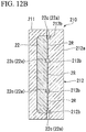
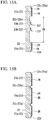
FIGS. 13A, 13B , and14 , theprint layer 23 is formed. Note thatFIG. 13A and14 are cross-sectional views at the same position asFIG. 10A , andFIG. 13B is a cross-sectional view at the same position asFIG. 10B . First, as shown inFIGS. 13A and 13B , ink is transferred onto the printlayer forming region 2R of thetransparent member 22 by a printing method such as a silk printing method, and the ink is dried to form theouter print layer 23a. - Next, as shown in
FIG. 14 , ink is transferred onto the distal end surface 22f1 of theprotrusion 22f by a pad printing method, and the ink is dried to form theemblem print layer 23b. - Here, ink is transferred from a metallic die onto a
silicon pad 2P, and furthermore thepad 2P is pressed against the distal end surface 22f1 of theprotrusion 22f to transfer the ink onto the distal end surface 22f1. At this time, the area of the ink pressed against the distal end surface 22f1 is desirably slightly larger than the area of the distal end surface 22f1. As a result, theemblem print layer 23b can be reliably formed on the entire distal end surface 22f1. In the present embodiment, the distal end surface 22f1 of theprotrusion 22f and the circumferential surface 22f2 thereof are bent and connected to each other. That is, a connecting portion between the distal end surface 22f1 of theprotrusion 22f and the circumferential surface 22f2 thereof is angular. Therefore, even when the area of ink pressed against the distal end surface 22f1 is slightly larger than the area of the distal end surface 22f1, it is possible to prevent the ink from flowing around the circumferential surface 22f2. Even if the ink adheres to the circumferential surface 22f2 of theprotrusion 22f, the circumferential surface 22f2 is substantially parallel to a visual recognition direction of a viewer from the outside. Therefore, it is difficult to visually recognize the ink adhering to the circumferential surface 22f2. Therefore, it is possible to clarify the outline of the character "F" included in theemblem 2E. Such a step shown inFIG. 14 forms theemblem print layer 23b on the distal end surface 22f1 of theprotrusion 22f, corresponding to the colored layer forming step in the present invention. - Subsequently, as shown in
FIGS. 15A and 15B , thepaint layer 24 is formed. Note thatFIG. 15A is a cross-sectional view at the same position asFIG. 10A , andFIG. 15B is a cross-sectional view at the same position asFIG. 10B . Here, in a state in which aregion 2M where theemblem 2E shown inFIG. 15A is formed is masked, a silver mica paint is sprayed, for example, on a back side of thetransparent member 22 on which theprint layer 23 is formed, and the mica paint is dried to form thepaint layer 24. In thepaint layer 24 thus formed, thepaint layer 24 covering theprint layer 23 and directly adhering to the inner wall surface of the entire paintedrecess 22c is formed except for the region where theemblem 2E is formed. - Subsequently, as shown in
FIG. 16 , theinner core 25 is housed in the innercore housing recess 22b. Note thatFIG. 16 is a cross-sectional view at the same position asFIG. 10A . Here, theinner core 25 formed in parallel to formation of the above-describedtransparent member 22,print layer 23, orpaint layer 24 is housed in the innercore housing recess 22b. Theinner core 25 is formed by forming a glittering discontinuous metal film such as an indium layer on a base formed by injection molding in advance by a vacuum vapor deposition method, a sputtering method, or the like. Note that a topcoat layer or an undercoat layer is formed as necessary in theinner core 25. Such aninner core 25 is housed in the innercore housing recess 22b with the glittering discontinuous metal film facing a side of the inner wall surface of the innercore housing recess 22b. - Subsequently, as shown in
FIGS. 17A and17B , thesupport member 26 is formed. Note thatFIG. 17A is a cross-sectional view at the same position asFIG. 10A , andFIG. 17B is a cross-sectional view at the same position asFIG. 10B . Here, thetransparent member 22 having theinner core 25 disposed in the innercore housing recess 22b is disposed inside a die for injection molding, and insert molding for emitting a molten resin to the back side of thetransparent member 22 is performed to form thesupport member 26. Such asupport member 26 is welded to thetransparent member 22 by heat during insert molding and disposed so as to cover theinner core 25. As a result, theinner core 25 is fixed to thetransparent member 22. Such a step shown inFIGS. 17A and17B forms thesupport member 26, corresponding to the support member forming step in the present invention. Note that thetransparent member 22 and thesupport member 26 may be each individually formed by injection molding or the like, and then thetransparent member 22 and thesupport member 26 may be coupled together using an adhesive, a fastening member, or the like. Even in this case, thesupport member 26 supports thetransparent member 22. - The
radar cover 21 and the method for manufacturing theradar cover 21 according to the present embodiment as described above form theprotrusion 22f protruding from the bottom 22b1 of the innercore housing recess 22b formed on a back side of thetransparent member 22 and having the distal end surface 22f1 set as a print layer region on which theemblem print layer 23b is formed. - When such an
emblem print layer 23b formed on the distal end surface 22f1 of theprotrusion 22f is visually recognized from the outside, surroundings of theemblem print layer 23b are visually recognized to be brighter or darker than theemblem print layer 23b, and the character "F" formed by theemblem print layer 23b can have a stereoscopic appearance. Therefore, theradar cover 21 and the method for manufacturing theradar cover 21 according to the present embodiment can impart a stereoscopic effect to a character formed by theemblem print layer 23b formed on the inner wall surface of the innercore housing recess 22b. - In the
radar cover 21 and the method for manufacturing theradar cover 21 according to the present embodiment, the distal end surface 22f1 of theprotrusion 22f and the circumferential surface 22f2 thereof are bent and connected to each other. Therefore, even if ink forming theemblem print layer 23b adheres to the circumferential surface 22f2 of theprotrusion 22f, the circumferential surface 22f2 is substantially parallel to a visual recognition direction of a viewer from the outside. Therefore, it is difficult to visually recognize the ink adhering to the circumferential surface 22f2. Therefore, theradar cover 21 and the method for manufacturing theradar cover 21 according to the present embodiment can clarify the outline of the character "F" included in theemblem 2E. - In the
radar cover 21 and the method for manufacturing theradar cover 21 according to the present embodiment, the distal end surface 22f1 of theprotrusion 22f is positioned at a front side of thetransparent member 22 compared to the printlayer forming region 2R which is a back surface of thetransparent member 22. As described above, in theradar cover 21 and the method for manufacturing theradar cover 21 according to the present embodiment, it is not necessary to set the distal end surface 22f1 of theprotrusion 22f and the back surface of thetransparent member 22 so as to be the same surface. A visual recognition state of the character "F" slightly varies depending on the protrusion dimension 2d1 of theprotrusion 22f. Therefore, according to the present embodiment, regardless of the position of the back surface of thetransparent member 22, the distal end surface 22f1 of theprotrusion 22f can be disposed at a position suitable for a stereoscopic effect desired for the character "F". - In the method for manufacturing the
radar cover 21 of the present embodiment, the ink forming theemblem print layer 23b is transferred onto the distal end surface 22f1 of theprotrusion 22f by a pad printing method. Therefore, the ink can be easily transferred onto the distal end surface 22f1 of theprotrusion 22f. - Hitherto, the preferred embodiment of the present invention has been described with reference to the attached drawings, but the present invention is not limited to the above embodiment. The shapes, the combinations, and the like of the respective constituent members described in the above embodiment are merely examples, and various modifications can be made based on design requirement or the like without departing from the gist of the present invention.
- For example, in the above embodiment, the configuration in which the colored layer is the
emblem print layer 23b has been described. However, the present invention is not limited thereto, and the colored layer can be formed by painting or the like. - In the above embodiment, the configuration in which the
transparent member 22 has the innercore housing recess 22b and the paintedrecess 22c as therecess 22a, and furthermore the paintedrecess 22c has the frame-like portion 22d and the mesh-like portion 22e has been described. However, the present invention is not limited thereto, and can be applied to a radar cover including a transparent member with a recess having a colored layer formed on an inner wall surface thereof and a method for manufacturing the radar cover. - In the above embodiment, the configuration in which the
inner core 25 is housed in the innercore housing recess 22b of thetransparent member 22 and theinner core 25 is sandwiched between thetransparent member 22 and thesupport member 26 to form theemblem 2E has been described. However, the present invention is not limited thereto. For example, the present invention can be applied to a radar cover having a configuration in which a glittering discontinuous film is directly formed on a front surface of thetransparent member 22 or thesupport member 26 and theinner core 25 is omitted, and a method for manufacturing the radar cover. -
- 11, 21: Radar cover
- 12, 22: Transparent member
- 12a, 22a: Recess
- 12b, 22b: Inner core housing recess
- 12c, 22c: Painted recess
- 12d, 22d: Frame-like portion
- 12e, 22e: Mesh-like portion
- 12f: Longitudinal recess (extension recess)
- 12g: Lateral recess (extension recess)
- 12g1: Upper connection surface (first connection surface)
- 12g2: Lower connection surface (second connection surface)
- 12g3: Intermediate surface
- 12g4: Upper curved surface (first curved surface)
- 12g5: Lower curved surface (second curved surface)
- 12g6: Main design surface
- 12h: Upper lateral recess (upper extension recess)
- 12i: Lower lateral recess (lower extension recess)
- 13, 23: Print layer
- 14, 24: Paint layer
- 15, 25: Inner core
- 16, 26: Support member
- 1D, 2D: Outer design portion
- IE, 2E: Emblem
- IX, 2X: Radar unit
- 22f: Protrusion
- 22f1: Distal end surface
- 22f2: Circumferential surface
- 23a: Outer print layer
- 23b: Emblem print layer (colored layer)
- R: Print layer forming region
Claims (13)
- A radar cover disposed on a path of a radio wave of a radar unit for detecting a surrounding situation of a vehicle,
the radar cover comprising: a transparent member; and a support member for supporting a back surface of the transparent member, wherein
the transparent member comprises an extension recess recessed toward a front surface side from the back surface, extending along the back surface, and comprising a paint layer formed on an inner wall surface thereof, and
the inner wall surface of the extension recess comprises:a first connection surface disposed on a first side in an orthogonal cross section with respect to an extension direction of the extension recess and connected to the back surface;a second connection surface disposed on a second side in the orthogonal cross section and connected to the back surface; andan intermediate surface connected to each of the first connection surface and the second connection surface and comprising a main design surface disposed such that a direction in which the main design surface is oriented is different from each of the first connection surface and the second connection surface. - The radar cover according to claim 1, comprising a lateral recess configured as the extension recess and extending in a horizontal direction, wherein
the main design surface is a flat surface inclined so as to extend downward toward a front surface side of the transparent member. - The radar cover according to claim 1 or 2, wherein the main design surface is wider than each of the first connection surface and the second connection surface.
- The radar cover according to any one of claims 1 to 3, comprising:an upper extension recess configured as the extension recess and disposed above a center of the transparent member in an up-down direction; anda lower extension recess configured as the extension recess and disposed below the center of the transparent member in the up-down direction.
- The radar cover according to any one of claims 1 to 4, wherein the paint layer is formed of a mica paint comprising mica particles.
- The radar cover according to any one of claims 1 to 5, wherein
the intermediate surface comprises:a first curved surface connected to the first connection surface; anda second curved surface connected to the second connection surface, andthe main design surface is disposed between the first curved surface and the second curved surface and formed in a flat surface. - A radar cover disposed on a path of a radio wave of a radar unit for detecting a surrounding situation of a vehicle, the radar cover comprising:a transparent member comprising a recess formed on a back surface thereof; a colored layer formed on an inner wall surface of the recess; and a support member for supporting the back surface of the transparent member, whereinthe transparent member comprises a protrusion protruding from a bottom of the recess and comprising the colored layer formed on a distal end surface thereof.
- The radar cover according to claim 7, wherein the distal end surface of the protrusion is connected to a circumferential surface of the protrusion such that a connecting portion between the distal end surface and the circumferential surface is angular.
- The radar cover according to claim 7 or 8, wherein the distal end surface of the protrusion is positioned at a front surface side of the transparent member compared to the back surface of the transparent member.
- A method for manufacturing a radar cover disposed on a path of a radio wave of a radar unit for detecting a surrounding situation of a vehicle, wherein
the radar cover comprises: a transparent member comprising a recess formed on a back surface thereof; a colored layer formed on an inner wall surface of the recess; and a support member for supporting the back surface of the transparent member, and
the method comprises:a transparent member forming step of forming the transparent member comprising a protrusion protruding from a bottom of the recess and comprising the colored layer formed on a distal end surface thereof;a coloring layer forming step of forming the colored layer on the distal end surface of the protrusion; anda support member forming step of forming the support member. - The method for manufacturing a radar cover according to claim 10, wherein in the transparent member forming step, the transparent member is formed such that a connecting portion between the distal end surface of the protrusion and a circumferential surface of the protrusion is angular.
- The method for manufacturing a radar cover according to claim 10 or 11, wherein in the transparent member forming step, the transparent member is formed such that the distal end surface of the protrusion is positioned at a front surface side of the transparent member compared to the back surface of the transparent member.
- The method for manufacturing a radar cover according to any one of claims 10 to 12, wherein in the colored layer forming step, the colored layer is formed on the distal end surface of the protrusion by transferring ink by a pad printing method.
Applications Claiming Priority (3)
| Application Number | Priority Date | Filing Date | Title |
|---|---|---|---|
| JP2016239660A JP2018094999A (en) | 2016-12-09 | 2016-12-09 | Radar cover |
| JP2016252958A JP6609542B2 (en) | 2016-12-27 | 2016-12-27 | Radar cover and radar cover manufacturing method |
| PCT/JP2017/043783 WO2018105644A1 (en) | 2016-12-09 | 2017-12-06 | Radar cover and manufacturing method for radar cover |
Publications (2)
| Publication Number | Publication Date |
|---|---|
| EP3552884A1 true EP3552884A1 (en) | 2019-10-16 |
| EP3552884A4 EP3552884A4 (en) | 2020-07-29 |
Family
ID=62492319
Family Applications (1)
| Application Number | Title | Priority Date | Filing Date |
|---|---|---|---|
| EP17879406.1A Withdrawn EP3552884A4 (en) | 2016-12-09 | 2017-12-06 | RADAR COVER AND PRODUCTION METHOD FOR A RADAR COVER |
Country Status (4)
| Country | Link |
|---|---|
| US (1) | US11199609B2 (en) |
| EP (1) | EP3552884A4 (en) |
| CN (1) | CN110023146B (en) |
| WO (1) | WO2018105644A1 (en) |
Families Citing this family (13)
| Publication number | Priority date | Publication date | Assignee | Title |
|---|---|---|---|---|
| JP7077718B2 (en) * | 2018-03-29 | 2022-05-31 | 豊田合成株式会社 | Radio wave transmission cover |
| CN112424630B (en) * | 2018-05-17 | 2024-09-03 | 育代株式会社 | Decorative components |
| JP6719506B2 (en) * | 2018-06-26 | 2020-07-08 | Nissha株式会社 | Electromagnetic wave transparent cover and manufacturing method thereof |
| JP6954941B2 (en) * | 2019-02-28 | 2021-10-27 | 株式会社ファルテック | Radar cover |
| JP7094911B2 (en) * | 2019-03-07 | 2022-07-04 | 三恵技研工業株式会社 | Radome for in-vehicle radar equipment |
| CN113574123B (en) | 2019-04-12 | 2023-01-10 | 埃卡特有限公司 | Radar frequency-transparent effect pigment mixtures, formulations and coatings thereof |
| EP4028790A1 (en) * | 2019-09-11 | 2022-07-20 | HELLA Saturnus Slovenija d.o.o. | A device for attachment to an opening of a vehicle and for covering an emitter and/or a receiver |
| KR102314016B1 (en) * | 2019-10-14 | 2021-10-19 | 주식회사 서연이화 | Method of producing Radio Wave Penetration Cover |
| JP7196820B2 (en) * | 2019-11-11 | 2022-12-27 | 豊田合成株式会社 | hot stamping equipment |
| FR3105607B1 (en) * | 2019-12-24 | 2022-12-09 | Cie Plastic Omnium Se | Motor vehicle radome |
| CN117795368A (en) * | 2021-07-07 | 2024-03-29 | 黑拉萨图尔努丝斯洛文尼亚有限责任公司 | System for backlighting a radome and radar device |
| JP2023098311A (en) * | 2021-12-28 | 2023-07-10 | 本田技研工業株式会社 | Structure to attach object detection device to vehicle body |
| JP7518871B2 (en) * | 2022-05-24 | 2024-07-18 | 森六テクノロジー株式会社 | Vehicle cover device |
Family Cites Families (38)
| Publication number | Priority date | Publication date | Assignee | Title |
|---|---|---|---|---|
| JP4022819B2 (en) * | 2002-12-26 | 2007-12-19 | 豊田合成株式会社 | Radio wave transmission cover |
| JP2004244516A (en) * | 2003-02-14 | 2004-09-02 | Toyoda Gosei Co Ltd | Electromagnetic wave-permeable glossy coated product |
| US6897819B2 (en) * | 2003-09-23 | 2005-05-24 | Delphi Technologies, Inc. | Apparatus for shaping the radiation pattern of a planar antenna near-field radar system |
| JP2005212745A (en) * | 2004-02-02 | 2005-08-11 | Toyota Motor Corp | Molded product for beam path of radar equipment |
| JP2007142780A (en) * | 2005-11-17 | 2007-06-07 | Toyoda Gosei Co Ltd | Decorative component for vehicle |
| JP4732147B2 (en) * | 2005-11-21 | 2011-07-27 | 豊田合成株式会社 | Resin product, method for producing the same, and method for forming metal film |
| JP5061539B2 (en) * | 2005-11-21 | 2012-10-31 | 豊田合成株式会社 | Resin product, method for producing the same, and method for forming metal film |
| US7352335B2 (en) * | 2005-12-20 | 2008-04-01 | Honda Elesys Co., Ltd. | Radar apparatus having arrayed horn antenna parts communicated with waveguide |
| JP2007240358A (en) * | 2006-03-09 | 2007-09-20 | Honda Motor Co Ltd | Exterior parts for vehicles |
| EP1972504B8 (en) * | 2007-03-22 | 2018-03-21 | Toyoda Gosei Co., Ltd. | Radio wave transmission cover and method of manufacturing the same |
| US7990334B2 (en) * | 2007-06-13 | 2011-08-02 | Toyoda Gosei Co., Ltd. | Radio wave transmission cover and method of manufacturing radio wave transmission cover |
| JP4720866B2 (en) * | 2008-07-30 | 2011-07-13 | 豊田合成株式会社 | Decorative member and manufacturing method thereof |
| JP5401132B2 (en) * | 2009-01-20 | 2014-01-29 | 信越ポリマー株式会社 | Radio wave transmitting decorative member and manufacturing method thereof |
| JP4881984B2 (en) * | 2009-08-28 | 2012-02-22 | 株式会社ファルテック | Manufacturing method of radome |
| IT1396079B1 (en) * | 2009-10-16 | 2012-11-09 | Zanini Holding S P A | PROCESS OF MANUFACTURE OF A DECORATIVE ELEMENT, PARTICULARLY INTENDED FOR USE AS AN EMBLEM ON A MOTOR VEHICLE. |
| US9114760B2 (en) * | 2010-11-15 | 2015-08-25 | Zanini Auto Grup, Sa | Decorative radome for automotive vehicular applications |
| JP5656581B2 (en) * | 2010-11-19 | 2015-01-21 | 株式会社ファルテック | Manufacturing method of radome |
| JP5690560B2 (en) * | 2010-11-19 | 2015-03-25 | 株式会社ファルテック | Hot stamp method |
| JP2014069634A (en) * | 2012-09-28 | 2014-04-21 | Toyoda Gosei Co Ltd | Vehicle decorative member |
| KR101459910B1 (en) | 2013-05-28 | 2014-11-07 | 현대자동차주식회사 | Radar apparatus for vehicle |
| JP6108173B2 (en) * | 2013-09-26 | 2017-04-05 | 豊田合成株式会社 | Decorative materials for vehicles |
| JP2015099081A (en) * | 2013-11-19 | 2015-05-28 | 豊田合成株式会社 | Electric wave transparent cover, and method of manufacturing the same |
| JP2016080479A (en) | 2014-10-15 | 2016-05-16 | 豊田合成株式会社 | Radio wave transmissive cover |
| JP6331098B2 (en) * | 2015-02-05 | 2018-05-30 | 豊田合成株式会社 | Radio wave transmission cover for vehicles |
| JP6467985B2 (en) * | 2015-02-25 | 2019-02-13 | 豊田合成株式会社 | Manufacturing method of electromagnetic wave transmission cover |
| JP6518104B2 (en) * | 2015-03-26 | 2019-05-22 | 株式会社ファルテック | Vehicle attachment |
| US10351077B2 (en) * | 2015-08-25 | 2019-07-16 | Mazda Motor Corporation | Vehicle member |
| CN105109417A (en) * | 2015-08-26 | 2015-12-02 | 宁波邦盛汽车零部件有限公司 | Covering part of radar of automobile adaptive cruise control (ACC) system |
| DE102015217744A1 (en) * | 2015-09-16 | 2017-03-16 | Nanogate PD Systems GmbH | Radom |
| JP6450671B2 (en) * | 2015-11-16 | 2019-01-09 | 豊田合成株式会社 | Decorative body and manufacturing method thereof |
| US10840601B2 (en) * | 2016-03-14 | 2020-11-17 | Pioneer Corporation | Horn antenna array |
| US11827158B2 (en) * | 2016-06-09 | 2023-11-28 | Zanini Auto Grup, S.A. | Radome for vehicles |
| WO2018010762A1 (en) * | 2016-07-11 | 2018-01-18 | Zanini Auto Grup, S.A. | Radome for vehicles |
| KR101887753B1 (en) * | 2016-08-29 | 2018-08-13 | 현대자동차주식회사 | Cover for smart cruise control radar |
| JP6872336B2 (en) * | 2016-09-27 | 2021-05-19 | 株式会社ファルテック | Radar cover |
| EP3530524A4 (en) | 2016-11-30 | 2020-10-21 | Faltec Co., Ltd. | RADAR COVER AND METHOD OF MANUFACTURING THE RADAR COVER |
| US20180159207A1 (en) * | 2016-12-02 | 2018-06-07 | Srg Global Inc. | Multi-piece vehicle radome having non-uniform back piece |
| US10627092B2 (en) * | 2018-03-05 | 2020-04-21 | Ford Global Technologies, Llc | Vehicle grille assembly |
-
2017
- 2017-12-06 WO PCT/JP2017/043783 patent/WO2018105644A1/en not_active Ceased
- 2017-12-06 US US16/349,497 patent/US11199609B2/en active Active
- 2017-12-06 CN CN201780074546.3A patent/CN110023146B/en active Active
- 2017-12-06 EP EP17879406.1A patent/EP3552884A4/en not_active Withdrawn
Also Published As
| Publication number | Publication date |
|---|---|
| US11199609B2 (en) | 2021-12-14 |
| EP3552884A4 (en) | 2020-07-29 |
| WO2018105644A1 (en) | 2018-06-14 |
| CN110023146B (en) | 2023-03-28 |
| CN110023146A (en) | 2019-07-16 |
| US20190293752A1 (en) | 2019-09-26 |
Similar Documents
| Publication | Publication Date | Title |
|---|---|---|
| EP3552884A1 (en) | Radar cover and manufacturing method for radar cover | |
| JP6872336B2 (en) | Radar cover | |
| CN109982896B (en) | Radome and method of manufacturing radome | |
| US11726167B2 (en) | Radar cover and method for manufacturing radar cover | |
| JP2020139853A (en) | Radar cover | |
| JP2019128255A (en) | Radar cover, and radar cover manufacturing method | |
| JP6609542B2 (en) | Radar cover and radar cover manufacturing method | |
| JP6837097B2 (en) | Radar cover | |
| JP7267036B2 (en) | radar cover | |
| JP6518644B2 (en) | Radar cover | |
| JP6932155B2 (en) | Radar cover and radar cover manufacturing method | |
| JP6783904B2 (en) | Radar cover and radar cover manufacturing method | |
| JP6492048B2 (en) | Radar cover and radar cover manufacturing method | |
| JP2018115910A (en) | Radar cover | |
| JP6809886B2 (en) | Radar cover and radar cover manufacturing method | |
| JP6954962B2 (en) | Radar cover and radar cover manufacturing method | |
| JP6574751B2 (en) | Radar cover | |
| JP7034123B2 (en) | Radar cover | |
| JP2018094999A (en) | Radar cover | |
| JP7076415B2 (en) | Radar cover manufacturing method | |
| JP2018089992A (en) | Radar cover and radar cover manufacturing method | |
| JP2006333728A (en) | Reel leg fixing device | |
| JP7149832B2 (en) | RADAR COVER AND METHOD FOR MANUFACTURING RADAR COVER | |
| JP7221034B2 (en) | RADAR COVER AND METHOD FOR MANUFACTURING RADAR COVER | |
| JP2020038183A (en) | Radar cover |
Legal Events
| Date | Code | Title | Description |
|---|---|---|---|
| STAA | Information on the status of an ep patent application or granted ep patent |
Free format text: STATUS: THE INTERNATIONAL PUBLICATION HAS BEEN MADE |
|
| PUAI | Public reference made under article 153(3) epc to a published international application that has entered the european phase |
Free format text: ORIGINAL CODE: 0009012 |
|
| STAA | Information on the status of an ep patent application or granted ep patent |
Free format text: STATUS: REQUEST FOR EXAMINATION WAS MADE |
|
| 17P | Request for examination filed |
Effective date: 20190417 |
|
| AK | Designated contracting states |
Kind code of ref document: A1 Designated state(s): AL AT BE BG CH CY CZ DE DK EE ES FI FR GB GR HR HU IE IS IT LI LT LU LV MC MK MT NL NO PL PT RO RS SE SI SK SM TR |
|
| AX | Request for extension of the european patent |
Extension state: BA ME |
|
| DAV | Request for validation of the european patent (deleted) | ||
| DAX | Request for extension of the european patent (deleted) | ||
| A4 | Supplementary search report drawn up and despatched |
Effective date: 20200629 |
|
| RIC1 | Information provided on ipc code assigned before grant |
Ipc: H01Q 1/42 20060101ALI20200623BHEP Ipc: G01S 13/86 20060101ALI20200623BHEP Ipc: G01S 7/03 20060101AFI20200623BHEP Ipc: G01S 13/931 20200101ALI20200623BHEP |
|
| STAA | Information on the status of an ep patent application or granted ep patent |
Free format text: STATUS: EXAMINATION IS IN PROGRESS |
|
| 17Q | First examination report despatched |
Effective date: 20221216 |
|
| REG | Reference to a national code |
Ref country code: DE Ref legal event code: R079 Free format text: PREVIOUS MAIN CLASS: B60R0013000000 Ipc: G01S0007030000 |
|
| GRAP | Despatch of communication of intention to grant a patent |
Free format text: ORIGINAL CODE: EPIDOSNIGR1 |
|
| STAA | Information on the status of an ep patent application or granted ep patent |
Free format text: STATUS: GRANT OF PATENT IS INTENDED |
|
| RIC1 | Information provided on ipc code assigned before grant |
Ipc: B60R 13/00 20060101ALI20240705BHEP Ipc: B29C 45/16 20060101ALI20240705BHEP Ipc: H01Q 1/42 20060101ALI20240705BHEP Ipc: G01S 13/86 20060101ALI20240705BHEP Ipc: G01S 13/931 20200101ALI20240705BHEP Ipc: G01S 7/03 20060101AFI20240705BHEP |
|
| INTG | Intention to grant announced |
Effective date: 20240718 |
|
| STAA | Information on the status of an ep patent application or granted ep patent |
Free format text: STATUS: THE APPLICATION IS DEEMED TO BE WITHDRAWN |
|
| 18D | Application deemed to be withdrawn |
Effective date: 20241119 |