JP7149832B2 - RADAR COVER AND METHOD FOR MANUFACTURING RADAR COVER - Google Patents
RADAR COVER AND METHOD FOR MANUFACTURING RADAR COVER Download PDFInfo
- Publication number
- JP7149832B2 JP7149832B2 JP2018231659A JP2018231659A JP7149832B2 JP 7149832 B2 JP7149832 B2 JP 7149832B2 JP 2018231659 A JP2018231659 A JP 2018231659A JP 2018231659 A JP2018231659 A JP 2018231659A JP 7149832 B2 JP7149832 B2 JP 7149832B2
- Authority
- JP
- Japan
- Prior art keywords
- decorative
- transparent member
- visible
- radar cover
- colored core
- Prior art date
- Legal status (The legal status is an assumption and is not a legal conclusion. Google has not performed a legal analysis and makes no representation as to the accuracy of the status listed.)
- Active
Links
Images


Classifications
-
- Y—GENERAL TAGGING OF NEW TECHNOLOGICAL DEVELOPMENTS; GENERAL TAGGING OF CROSS-SECTIONAL TECHNOLOGIES SPANNING OVER SEVERAL SECTIONS OF THE IPC; TECHNICAL SUBJECTS COVERED BY FORMER USPC CROSS-REFERENCE ART COLLECTIONS [XRACs] AND DIGESTS
- Y02—TECHNOLOGIES OR APPLICATIONS FOR MITIGATION OR ADAPTATION AGAINST CLIMATE CHANGE
- Y02A—TECHNOLOGIES FOR ADAPTATION TO CLIMATE CHANGE
- Y02A90/00—Technologies having an indirect contribution to adaptation to climate change
- Y02A90/10—Information and communication technologies [ICT] supporting adaptation to climate change, e.g. for weather forecasting or climate simulation
Description
本発明は、レーダカバー及びレーダカバーの製造方法に関するものである。 The present invention relates to a radar cover and a radar cover manufacturing method.
近年、ミリ波等の電波を用いて車両の周囲の障害物等を検知するレーダユニットが車両に搭載されている。このようなレーダユニットは、エンブレム等の識別マークが形成されたレーダカバーに前方から覆われた状態で車両の内部に配置されている。 In recent years, vehicles are equipped with radar units that detect obstacles and the like around the vehicle using radio waves such as millimeter waves. Such a radar unit is arranged inside a vehicle while being covered from the front with a radar cover on which an identification mark such as an emblem is formed.
レーダカバーは、レーダユニットにおいて送受信される電波を極力減衰させずに透過可能である必要がある。一方で、レーダカバーに形成されたエンブレム等の識別マークの質感を高めるためには、レーダカバーの一部に対して金属光沢を付与する必要がある。このため、レーダカバーでは、例えばレーダカバーの表面側に配置される透光部材の裏面に凹部を形成し、この凹部に電波を透過可能なインジウムの蒸着層やスパッタリング層を形成することで金属光沢を得つつ電波を透過可能としている。 The radar cover needs to be able to transmit radio waves transmitted and received by the radar unit without attenuating them as much as possible. On the other hand, in order to enhance the texture of identification marks such as emblems formed on the radar cover, it is necessary to impart a metallic luster to a portion of the radar cover. For this reason, in the radar cover, for example, a concave portion is formed on the back surface of the light-transmitting member arranged on the front side of the radar cover, and an indium vapor-deposited layer or a sputtering layer capable of transmitting radio waves is formed in the concave portion to achieve metallic luster. It is possible to transmit radio waves while obtaining
ところで、近年、上述のようなレーダカバーにおいて、エンブレム等の識別マークの縁に沿って加飾を行う場合がある。このような場合には、例えば識別マークの側方に対して加飾部材を配置し、透明部材を介して外部から加飾部材を視認可能とすることが考えられる。しかしながら、識別マークの縁に沿って施される加飾は、識別マークと比較して微細であることが一般的である。このため、加飾部材が極めて小さな部材となり、形成が困難となる場合がある。 By the way, in recent years, in the radar cover as described above, there is a case where decoration is performed along the edge of the identification mark such as the emblem. In such a case, for example, it is conceivable to dispose the decorative member on the side of the identification mark so that the decorative member can be visually recognized from the outside through a transparent member. However, the decoration applied along the edge of the identification mark is generally finer than the identification mark. For this reason, the decorative member becomes an extremely small member, which may be difficult to form.
本発明は、上述する問題点に鑑みてなされたもので、識別マーク等を有するレーダカバーにおいて、識別マーク等の縁に沿って容易に微細な加飾を施すことを可能とすることを目的とする。 SUMMARY OF THE INVENTION It is an object of the present invention to provide a radar cover having an identification mark or the like, and to enable fine decoration to be easily applied along the edge of the identification mark or the like. do.
本発明は、上記課題を解決するための手段として、以下の構成を採用する。 The present invention employs the following configurations as means for solving the above problems.
第1の発明は、背面に凹部が設けられた透明部材と、上記透明部材の凹部に収容される有色コアと、上記透明部材の背面と接合された支持部材とを備えるレーダカバーであって、上記有色コアの縁部に沿って加飾を施す加飾部を備え、上記加飾部が、上記有色コアの縁部に沿って上記有色コアの側方に配置された可視部と、上記可視部と接合されると共に少なくとも一部が上記有色コアの背面側に配置された背面接続部とを有するという構成を採用する。 A first invention is a radar cover comprising: a transparent member provided with a concave portion on the back surface; a colored core accommodated in the concave portion of the transparent member; and a support member joined to the back surface of the transparent member, a decorative portion that decorates along the edge of the colored core, wherein the decorative portion is arranged to the side of the colored core along the edge of the colored core; and a back connecting portion joined to the colored core and at least a part of which is arranged on the back side of the colored core.
第2の発明は、上記第1の発明において、上記加飾部が、単一の上記有色コアの縁部に沿って配置された複数の上記可視部と、複数の上記可視部に接続された背面接続部とを有するという構成を採用する。 In a second aspect based on the first aspect, the decorative portion is connected to the plurality of visible portions arranged along the edge of the single colored core and to the plurality of visible portions. A configuration is adopted in which a rear connecting portion is provided.
第3の発明は、上記第1または第2の発明において、上記加飾部の全体が同一材料により形成されているという構成を採用する。 A third invention adopts a configuration in which the entire decorative portion is made of the same material in the first or second invention.
第4の発明は、上記第1~第3いずれかの発明において、上記透明部材が、上記有色コアの縁部に沿って上記透明部材の背面に設けられた加飾凹部を有し、上記可視部が、上記加飾凹部に配置されているという構成を採用する。 A fourth invention is any one of the first to third inventions, wherein the transparent member has a decorative recess provided on the back surface of the transparent member along the edge of the colored core, and the visible is disposed in the decorative recess.
第5の発明は、上記第1~第3いずれかの発明において、上記可視部の上記透明部材側の表面と、上記背面接続部の上記有色コア側の表面とが、面一であるという構成を採用する。 According to a fifth aspect, in any one of the first to third aspects, a surface of the visible portion on the transparent member side and a surface of the rear connection portion on the colored core side are flush with each other. to adopt.
第6の発明は、背面に凹部が設けられた透明部材を形成する透明部材形成工程と、上記透明部材の凹部に収容される有色コアを形成する有色コア形成工程と、上記凹部に上記有色コアが収容された上記透明部材の背面に接合される支持部材を形成する支持部材形成工程とを有するレーダカバーの製造方法であって、上記支持部材形成工程よりも前に、上記凹部に収容された有色コアの縁部に沿って加飾を施す加飾部を形成する加飾部形成工程を有し、上記加飾部が、上記有色コアの縁部に沿って上記有色コアの側方に配置された可視部と、上記可視部と接合されると共に少なくとも一部が上記有色コアの背面側に配置された背面接続部とを有するという構成を採用する。 A sixth aspect of the invention includes a transparent member forming step of forming a transparent member having a concave portion on the back surface thereof, a colored core forming step of forming a colored core to be accommodated in the concave portion of the transparent member, and a colored core forming step of forming the colored core in the concave portion. a support member forming step of forming a support member bonded to the back surface of the transparent member in which the transparent member is accommodated in the recess before the support member forming step; A decorating portion forming step of forming a decorating portion for decorating along the edge of the colored core, wherein the decorating portion is arranged laterally of the colored core along the edge of the colored core. and a back connecting part joined to the visible part and having at least a part thereof arranged on the back side of the colored core.
第7の発明は、上記第6の発明において、上記加飾部が、単一の上記有色コアの縁部に沿って配置された複数の上記可視部と、複数の上記可視部に接続された背面接続部とを有するという構成を採用する。 In a seventh aspect based on the sixth aspect, the decorative portion is connected to the plurality of visible portions arranged along the edge of the single colored core and to the plurality of visible portions. A configuration is adopted in which a rear connecting portion is provided.
第8の発明は、上記第6または第7の発明において、上記加飾部形成工程にて、上記加飾部の上記背面接続部を成形する空間に接続されたゲートを介して、溶融樹脂を供給する射出成形により上記加飾部を形成するという構成を採用する。 In an eighth invention based on the sixth or seventh invention, molten resin is supplied through a gate connected to a space for molding the back connecting portion of the decorating portion in the decorating portion forming step. A configuration is adopted in which the decorative portion is formed by injection molding of supply.
第9の発明は、上記透明部材形成工程にて、上記凹部の縁部に沿って加飾凹部を設け、上記加飾部形成工程にて、上記加飾凹部に上記可視部が配置されるように上記加飾部を形成するという構成を採用する。 In a ninth aspect of the invention, in the transparent member forming step, a decorative concave portion is provided along the edge of the concave portion, and in the decorative portion forming step, the visible portion is arranged in the decorative concave portion. A configuration is adopted in which the decorative portion is formed in the .
本発明によれば、加飾部が、有色コアの側方に配置された可視部と、有色コアの背面に配置された背面接続部とを有している。このため、外部から視認可能な可視部を微細としても、外部から視認不能な背面接続部によって、可視部のみから構成される場合よりも加飾部の大きさを大きくすることができる。したがって、本発明によれば、識別マーク等を有するレーダカバーにおいて、識別マーク等の縁に沿って容易に微細な加飾を施すことが可能となる。 According to the present invention, the decorative portion has the visible portion arranged on the side of the colored core and the back connecting portion arranged on the back of the colored core. Therefore, even if the visible portion visible from the outside is fine, the size of the decorative portion can be increased by the back connecting portion invisible from the outside, compared to the case where only the visible portion is formed. Therefore, according to the present invention, a radar cover having an identification mark or the like can be easily finely decorated along the edge of the identification mark or the like.
以下、図面を参照して、本発明に係るレーダカバー及びレーダカバーの製造方法の一実施形態について説明する。 An embodiment of a radar cover and a radar cover manufacturing method according to the present invention will be described below with reference to the drawings.
(第1実施形態)
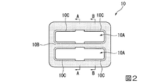
図1は、本実施形態のレーダカバー10を備えるラジエータグリル1の正面図である。また、図2は、本実施形態のレーダカバー10の拡大正面図である。
(First embodiment)
FIG. 1 is a front view of a radiator grille 1 having a
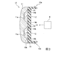
ラジエータグリル1は、車両のエンジンルームに通じる開口を塞ぐように車両の前面に設けられており、エンジンルームへの通気を確保しかつエンジンルームへの異物の進入を防止している。ラジエータグリル1の中央には、エンジンルーム内に配置されるレーダユニットR(図3参照)に対向するようにしてレーダカバー10が設けられている。レーダユニットRは、例えばミリ波を発信する発信部、反射波を受信する受信部、及び、演算処理を行う演算部等を有している。このレーダユニットRは、レーダカバー10を透過する電波の送受信を行い、受信した電波に基づいて車両の周囲状況を検知する。例えば、レーダユニットRは、障害物までの距離や障害物の相対速度等を算出して出力する。
A radiator grille 1 is provided in the front of the vehicle so as to block an opening leading to the engine room of the vehicle, ensuring ventilation to the engine room and preventing foreign matter from entering the engine room. A
レーダカバー10は、レーダユニットRを車両の正面側から見て覆うように配置されている。このレーダカバー10は、図2に示すように、車両の正面側から見て、車両メーカのエンブレム等の認識マークを示す図形や文字等を表す光輝領域10Aと、この光輝領域10Aの視認性を向上させる黒色領域10Bと、光輝領域10Aを縁取る加飾領域10Cとを有する部品である。例えば、加飾領域10Cは、黒色領域10Bと異なる青等の色とされている。また、本実施形態において、加飾領域10Cは、単一の光輝領域10A(後述するインナコア12)に対して2つ設けられており、各々が光輝領域10Aの縁に沿って湾曲した形状とされている。
The
図3は、図2の模式的なA-A断面図である。図4は、図2の模式的なB-B断面図である。これらの図に示すように、レーダカバー10は、透明部材11と、インナコア12(有色コア)と、ベース部材13(支持部材)と、加飾部材14とを備えている。透明部材11は、最も車両の外側に配置される略矩形状の透明樹脂材料により形成される部位である。この透明部材11は、車両の外部からのインナコア12の視認性を高めるため、表側の面が円滑面とされている。また、透明部材11の背面には、インナコア12が配置される収容凹部11a(凹部)が形成されている。
FIG. 3 is a schematic cross-sectional view taken along line AA of FIG. FIG. 4 is a schematic cross-sectional view taken along line BB of FIG. As shown in these drawings, the
収容凹部11aは、インナコア12を収容する部位であり、収容されたインナコア12を車両の前方側から立体的に視認可能とする。この収容凹部11aは、車両メーカのエンブレム等の認識マークの図形や文字等の形状に沿って設けられている。図3に示すように、このような収容凹部11aにインナコア12が配置されることによって、上述の光輝領域10Aが形成される。
The accommodation recess 11a is a portion that accommodates the
また、透明部材11の背面には、加飾部材14の一部(後述する可視部14a)が収容される加飾凹部11bが形成されている。加飾凹部11bは、収容凹部11aよりも浅い凹部であり、収容された加飾部材14の一部を車両の前方側から立体的に視認可能とする。この加飾凹部11bは、収容凹部11aを囲うように環状に設けられており、すなわち正面側から見てインナコア12の縁部に隣接して設けられている。このように、本実施形態において、透明部材11は、インナコア12の縁部に隣接して設けられた加飾凹部11bを有している。このような加飾凹部11bに加飾部材14の可視部14aが配置されることによって、上述の加飾領域10Cが形成される。
A
このような透明部材11は、例えば、無色のPC(ポリカーボネート)やPMMA(ポリメタクリル酸メチル樹脂)等の透明合成樹脂によって形成されており、1.5mm~10mm程度の厚さとされている。また、透明部材11の表側の面には、必要に応じて、傷付き防止のためのハードコート処理、又はウレタン系塗料のクリヤコート処理が施される。なお、耐傷性を備える透明合成樹脂であれば、これらの傷付き防止処理は不要である。
Such a
インナコア12は、基部と、ベースコート層と、光輝性膜と、トップコート層とが積層されて形成されている。なお、図面における視認性を向上させるために、インナコア12は複数層に分割して図示していない。基部は射出成形等によって成形されており、例えばABS、PC又はPET等の合成樹脂によって形成されている。この基部は、透明部材の収容凹部11aを埋設する凸状の形状とされており、透明部材11の収容凹部11aに嵌合される。ベースコート層は、基部と光輝性膜との間に形成されており、基部と光輝性膜との密着性を向上させるためのものである。このベースコート層は、例えば、透明(着色透明を含む)な合成樹脂を用いたクリヤー塗装によって形成されている。
The
光輝性膜は、基部の表側の面(透明部材11側の面)に形成されており、基部に被さるように配置された金属光輝性を備える層である。この光輝性膜は、例えばインジウム(In)からなる金属製の薄膜である。この光輝性膜は、互いの間に隙間を有して配置される複数の島部を有する構造であり、多数の微細な隙間を有する不連続膜である。このような光輝性膜は、これらの隙間を通じて電波を透過可能とされている。このような光輝性膜によって、インナコア12は金属色とされている。
The glitter film is a layer having metal glitter that is formed on the surface of the front side of the base (the surface on the side of the transparent member 11) and is arranged so as to cover the base. This glitter film is a metallic thin film made of, for example, indium (In). This glittering film has a structure having a plurality of island portions arranged with gaps therebetween, and is a discontinuous film having many fine gaps. Such a glittering film allows radio waves to pass through these gaps. The
トップコート層は、光輝性膜を覆うように光輝性膜上に形成されており、光輝性膜を保護するためのものである。このトップコート層も、ベースコート層と同様に、透明(着色透明を含む)な合成樹脂を用いたクリヤー塗装によって形成されている。 The topcoat layer is formed on the glitter film so as to cover the glitter film and protects the glitter film. Like the base coat layer, this top coat layer is also formed by clear coating using a transparent (including colored transparent) synthetic resin.
なお、ベースコート層及びトップコート層は、酸化ケイ素(SiOx)からなる透明セラミックコート層とすることもできる。この場合には、クリヤー塗装等によって形成される樹脂からなるベースコート層やトップコート層と比較して高い耐熱性を有すると共に、高い電波透過性を有する。 The base coat layer and the top coat layer can also be transparent ceramic coat layers made of silicon oxide (SiOx). In this case, the base coat layer and top coat layer made of a resin formed by clear coating or the like have higher heat resistance and higher radio wave transmittance.
また、本実施形態において光輝性膜は、ベースコート層が形成された基部の表面に形成される。なお、密着性の高い光輝性膜を用いる場合には、ベースコート層を省略することも可能である。 Moreover, in this embodiment, the glitter film is formed on the surface of the base on which the base coat layer is formed. Note that the base coat layer may be omitted when a glittering film with high adhesion is used.
ベース部材13は、透明部材11の背面側に固着される部位であり、透明部材11を背面側から支持する。このベース部材13は、エンジンルーム側に突出する係合部13aを有している。この係合部13aは、先端部が爪状に成形されており、当該先端部が例えばラジエータグリル本体に係止される。
The
このようなベース部材13は、ABS(アクリロニトリル・ブタジエン・スチレン共重合合成樹脂)、AES(アクリロニトリル・エチレン・スチレン共重合合成樹脂)、ASA(アクリロニトリル・スチレン・アクリレート)、PBT(ポリブチレンテレフタレート)、有色のPC、PET等の合成樹脂、又はこれらの複合樹脂からなり、0.5mm~10mm程度の厚さとされている。
Such a
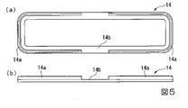
加飾部材14は、透明部材11とベース部材13との間に配置されており、各々のインナコア12に対応して設けられている。つまり、加飾部材14は、インナコア12の数と同数設けられており、本実施形態においては2つ設けられている。図5は、加飾部材14の形状を示す図であり、(a)が正面図であり、(b)が側面図である。これらの図に示すように、各々の加飾部材14は、透明部材11の加飾凹部11bに収容される可視部14aと、一部がインナコア12の背面に配置された背面接続部14bとを有している。
The
可視部14aは、透明部材11の加飾凹部11bを埋設する部位であり、透明部材11を介して外部より視認可能とされている。このような可視部14aは、加飾凹部11bに収容されることによって、上述の加飾領域10Cを形成している。本実施形態においては、1つの光輝領域10A(すなわち1つのインナコア12)に対して、2つの加飾領域10Cが設けられている。このため、各々の加飾部材14には、2つの可視部14aが設けられている。各々の可視部14aは、図5(a)に示すように、インナコア12の縁部に沿って湾曲した形状とされている。
The
背面接続部14bは、各々の可視部14aの背面に対して接続されており、2つの可視部14aを接続する環状の部位である。この背面接続部14bは、図5(a)に示すように、可視部14aよりも幅広とされており、可視部14aよりも径方向内側に張り出されるようにして設けられている。このような背面接続部14bは、可視部14aが設けられた領域に配置された部位が可視部14aの背面に配置されており、可視部14aが設けられていない領域に配置された部位がインナコア12の背面に配置されている。
The
このような加飾部材14は、背面接続部14bによって微細な可視部14aが保持された形状となっており、背面接続部14bによって複数の可視部14a同士が接続されかつ可視部14aよりも大きな形状とされている。このため、可視部14aの各々を単一の部品とする場合と比較して、容易に可視部14aを形成することができ、また可視部14aの剛性を向上させることができる。
Such a
一方で、背面接続部14bが可視部14aあるいはインナコア12の背面に配置されているため、透明部材11を介して視認可能な加飾部材14の部位は、可視部14aのみである。このため、加飾部材14によってレーダカバー10に対して微細な装飾を施すことが可能となっている。
On the other hand, since the
続いて、本実施形態のレーダカバー10の製造方法について、図6を参照して説明する。図6は、本実施形態のレーダカバー10の製造方法について説明するための概略図である。まず、図6(a)に示すように、透明部材11を形成する。例えば、透明部材11は、射出成形により形成される。この射出成形により、収容凹部11a及び加飾凹部11bを有する透明部材11を形成することができるため、後工程により収容凹部11a及び加飾凹部11bを形成する必要はない。なお、必要に応じて、透明部材11の表面側(車両外側に向く面)あるいは全面には、耐久性等を向上させるためのハードコート処理を施しても良い。この図6(a)で示す工程は、背面に収容凹部11aや加飾凹部11bが設けられた透明部材11を形成する透明部材形成工程に相当する。
Next, a method for manufacturing the
また、この透明部材11を形成するときには、透明部材11の収容凹部11a及び加飾凹部11bの内壁面の凹凸を小さくする処理を行うことが望ましい。この場合には、例えば、収容凹部11a及び加飾凹部11bの内壁面の算術平均粗さや最大高さが、透明部材11の裏面の収容凹部11a及び加飾凹部11bを除く領域の算術平均粗さや最大高さよりも小さくなるように研磨を行う。なお、透明部材11の収容凹部11a及び加飾凹部11bの内壁面の凹凸を小さくするための後加工を行うのではなく、射出成形に用いる金型において、収容凹部11a及び加飾凹部11bを形成する部位の表面粗さを予め小さくしておくことによっても、透明部材11の収容凹部11a及び加飾凹部11bの内壁面の凹凸を小さくすることができる。
Further, when forming the
次に、図6(b)に示すように、インナコア12を形成する。例えば、基部は、射出成形により形成される。また、基部に対してクリヤー塗装を行い、その後乾燥させることによりベースコート層を形成する。また、スパッタリングあるいは真空蒸着によってベースコート層上に光輝性膜を形成する。また、光輝性膜の表面に対してクリヤー塗装を行い、その後乾燥させることにより、トップコート層を形成する。なお、インナコア12の形成は、図6(a)で示した透明部材11の形成を待って行う必要はない。図6(a)で示した透明部材11の形成工程と並行して、インナコア12を形成することによって、レーダカバー10の製造時間を短縮することができる。この図6(b)で示す工程は、透明部材11の収容凹部11aに収容されるインナコア12を形成するインナコア形成工程(有色コア形成工程)に相当する。
Next, as shown in FIG. 6(b), the
続いて、図6(c)に示すように、インナコア12を透明部材11の収容凹部11aに嵌合する。次に、図6(d)に示すように、加飾部材14を形成する。ここでは、収容凹部11aにインナコア12が設置された透明部材11を、射出成形用の金型50の内部に配置し、透明部材11の背面側に溶融した樹脂を射出するインサート成形を行うことで、加飾部材14を形成する。このような加飾部材14は、インサート成形時の熱により透明部材11と溶着され、またインナコア12の背面の一部と溶着される。また、加飾部材14を射出成形によって形成することによって、溶融樹脂が加飾凹部11bに流れ込み、可視部14aを有する加飾部材14が形成される。また、加飾部材14が背面接続部14bを有しているため、背面接続部14bが設けられない場合と比較して溶融樹脂を流す金型の内部空間を広く確保できる。このため、溶融樹脂を微細な加飾凹部11bにまでより確実に流れ込ませることが可能となる。この図6(d)に示す工程は、ベース部材形成工程よりも前に、収容凹部11aに収容されたインナコア12の縁部に沿って加飾を施す加飾部材14を形成する加飾部材形成工程(加飾部形成工程)に相当する。
Subsequently, as shown in FIG. 6(c), the
また、図6(d)に示すように、金型50のゲート51は、溶融樹脂の吐出開口が加飾部材14の背面接続部14bを形成するための空間に配置されるように設けられている。このようなゲート51を介して、溶融された樹脂が金型50の内部空間に供給されることによって加飾部材14が形成される。
Further, as shown in FIG. 6(d), the
次に、図6(e)に示すように、ベース部材13を形成する。ここでは、加飾部材14が設けられた透明部材11を、射出成形用の金型の内部に配置し、透明部材11の背面側に溶融した樹脂を射出するインサート成形を行うことで、ベース部材13を形成する。このようなベース部材13は、インサート成形時の熱により透明部材11と溶着され、インナコア12及び加飾部材14を覆うように配置される。また、インナコア12の裏面及び加飾部材14の背面も、ベース部材13に溶着される。これによって、インナコア12及び加飾部材14がベース部材13により支持される。この図6(e)で示す工程は、収容凹部11aにインナコア12が収容された透明部材11の背面に接合されるベース部材13を形成するベース部材形成工程(支持部材形成工程)に相当する。
Next, as shown in FIG. 6(e), the
以上のような本実施形態のレーダカバー10及びレーダカバー10の製造方法によれば、加飾部材14が、インナコア12の側方に配置された可視部14aと、インナコア12の背面に配置された背面接続部14bとを有している。このため、外部から視認可能な可視部14aを微細化しても、外部から視認不能な背面接続部14bによって、可視部14aのみから加飾部材が構成される場合よりも加飾部材14の大きさを大きくすることができる。したがって、本実施形態のレーダカバー10によれば、識別マーク等の縁に沿って容易に微細な加飾を施すことが可能となる。
According to the
また、本実施形態のレーダカバー10によれば、加飾部材14が、単一のインナコア12に沿って配置された複数(2つ)の可視部14aと、複数の可視部14aに接続された背面接続部14bとを有している。このため、複数の可視部14a同士を、背面接続部14bを介して一体化することができ、1つの加飾部材14の大きさをより大きく確保することが可能となる。
Further, according to the
また、本実施形態のレーダカバー10においては、加飾部材14の全体が同一材料によって形成されている。このため、可視部14a及びは背面接続部14bを一度の工程で同時に形成することができる。
Moreover, in the
また、本実施形態のレーダカバー10の製造方法においては、背面接続部14bを成形する空間に接続されたゲート51を介して金型50の内部空間に溶融樹脂を供給する射出成形により加飾部材14を形成している。このため、ゲート51から供給された溶融樹脂が透明部材11の加飾凹部11bに直接噴き付けられることを防止し、加飾凹部11bの内壁面に影響を与えることを防止できる。
Further, in the method of manufacturing the
(第2実施形態)
次に、本発明の第2実施形態について、図7及び図8を参照して説明する。なお、本実施形態の説明において、上記第1実施形態と同様の部分については、同一の符号を付すと共に、その説明を省略あるいは簡略化する。
(Second embodiment)
Next, a second embodiment of the invention will be described with reference to FIGS. 7 and 8. FIG. In the description of this embodiment, the same reference numerals are given to the same parts as in the first embodiment, and the description thereof is omitted or simplified.
図7は、本実施形態のレーダカバー20の断面図であり、上記第1実施形態のレーダカバー10の説明に用いた図2のB-B断面に相当する位置での断面図である。この図に示すように、本実施形態のレーダカバー20においては、透明部材11の背面に対して加飾凹部11bが設けられていない。つまり、透明部材11の収容凹部11aの周囲が平面とされている。
FIG. 7 is a cross-sectional view of the
また、本実施形態のレーダカバー20は、上記第1実施形態の加飾部材14と比較して、加飾凹部11bに収容される突起状の部位が設けられていない断面略矩形状の加飾部材21を備えている。本実施形態において加飾部材21は、正面から見てインナコア12の縁部から外側に食み出した部位(インナコア12の側方に配置されるい部位)が可視部21aとされている。
Further, the
また、加飾部材21は、インナコア12の背面に配置された背面接続部21bを有している。なお、本実施形態においては、背面接続部21bは可視部21aの側面に接続されている。可視部21aの透明部材11側の表面と、背面接続部21bのインナコア12側の表面とが面一となるように、可視部21a及び背面接続部21bの厚さ寸法が定められている。
In addition, the
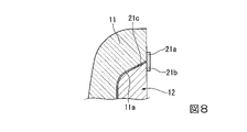
図8は、加飾部材21の可視部21aと背面接続部21bとの境界部分の模式的な拡大図である。この図に示すように、本実施形態のレーダカバー20において、加飾部材21は、可視部21aと背面接続部21bとの境界部位から透明部材11側に突出した微小突起部21cをさらに有している。この微小突起部21cは、インナコア12と透明部材11の収容凹部11aの内面との間の微小な隙間に配置されており、外部から透明部材11を介して視認可能とされている。なお、可視部21a及び微小突起部21cは、上記第
1実施形態における可視部14aと同様に、1つのインナコア12に対して2つ設けられている。
FIG. 8 is a schematic enlarged view of a boundary portion between the
このような微小突起部21cは、上記第1実施形態の加飾部材14と同様に射出成形によって加飾部材21を形成する際に、溶融樹脂が透明部材11とインナコア12との僅かな微小空間に入り込み、その後溶融樹脂が冷却されることによって形成される。なお、透明部材11とインナコア12との隙間は極めて微小であるが、図8の模式図においては、視認を容易とするために、大きく図示している。また、微小突起部21cの厚さ寸法も、透明部材11とインナコア12との隙間と同様に極めて微小であるが、図8の模式図においては、視認を容易とするために、大きく図示している。
このような微小突起部21cは、厚さ寸法が極めて微小であるものの、透明部材11とインナコア12との隙間の広い範囲に形成されるため、外部から容易に視認可能となっている。さらに、微小突起部21cは、透明部材11とインナコア12との隙間に沿ってベース部材13から透明部材11側に向けて切り立つように突出かつ湾曲しているため、加飾領域10Cをより立体的とすることが可能となる。つまり、このような構成の本実施形態のレーダカバー20によれば、透明部材11の背面に加飾凹部11bを設けなくても、加飾領域10Cを立体的にすることが可能となる。
Although the thickness dimension of the
以上、添付図面を参照しながら本発明の好適な実施形態について説明したが、本発明は上記実施形態に限定されないことは言うまでもない。上述した実施形態において示した各構成部材の諸形状や組み合わせ等は一例であって、本発明の趣旨から逸脱しない範囲において設計要求等に基づき種々変更可能である。 Although the preferred embodiments of the present invention have been described above with reference to the accompanying drawings, it goes without saying that the present invention is not limited to the above embodiments. The various shapes, combinations, and the like of the constituent members shown in the above-described embodiment are merely examples, and can be variously changed based on design requirements and the like without departing from the gist of the present invention.
例えば、上記第1実施形態においては、1つのインナコア12に対して2つの可視部14aが設けられた構成について説明した。しかしながら、本発明はこれに限定されるものではない。例えば、1つのインナコア12に対して1つあるいは3つ以上の可視部14aが設けられた構成を採用することも可能である。また、上記第2実施形態において、1つのインナコア12に対して、1つあるいは3つ以上の可視部21a及び微小突起部21cを設ける構成を採用することも可能である。
For example, in the above-described first embodiment, the configuration in which two
また、上記第2実施形態においては、加飾部材21が微小突起部21cを備える構成について説明した。しかしながら、本発明はこれに限定されるものではない。例えば、微小突起部21cを備えない加飾部材を設ける構成を採用することも可能である。
Further, in the above-described second embodiment, the configuration in which the
1……ラジエータグリル、10……レーダカバー、10A……光輝領域、10B……黒色領域、10C……加飾領域、11……透明部材、11a……収容凹部(凹部)、11b……加飾凹部、12……インナコア(有色コア)、13……ベース部材(支持部材)、13a……係合部、14……加飾部材(加飾部)、14a……可視部、14b……背面接続部、20……レーダカバー、21……加飾部材、21a……可視部、21b……背面接続部、21c……微小突起部、50……金型、51……ゲート、R……レーダユニット
Reference Signs List 1
Claims (9)
前記有色コアの縁部に沿って加飾を施す加飾部を備え、
前記加飾部は、
前記有色コアの縁部に沿って前記有色コアの側方に配置された可視部と、
前記可視部と接合されると共に少なくとも一部が前記有色コアの背面側に配置された背面接続部と
を有する
ことを特徴とするレーダカバー。 A radar cover comprising: a transparent member provided with a recess on the back surface; a colored core accommodated in the recess of the transparent member; and a support member joined to the back surface of the transparent member,
A decorating part for decorating along the edge of the colored core,
The decorating part is
a visible portion disposed laterally of the colored core along the edge of the colored core;
and a rear connecting portion that is joined to the visible portion and at least a portion of which is located on the rear side of the colored core.
前記支持部材形成工程よりも前に、前記凹部に収容された有色コアの縁部に沿って加飾を施す加飾部を形成する加飾部形成工程を有し、
前記加飾部は、
前記有色コアの縁部に沿って前記有色コアの側方に配置された可視部と、
前記可視部と接合されると共に少なくとも一部が前記有色コアの背面側に配置された背面接続部と
を有する
ことを特徴とするレーダカバーの製造方法。 A transparent member forming step of forming a transparent member having a concave portion provided on its back surface, a colored core forming step of forming a colored core accommodated in the concave portion of the transparent member, and the transparent member having the colored core accommodated in the concave portion. A method for manufacturing a radar cover, comprising: a supporting member forming step of forming a supporting member joined to the back surface of the member;
Prior to the supporting member forming step, a decorating portion forming step of forming a decorating portion for decorating along the edge of the colored core accommodated in the recess,
The decorating part is
a visible portion disposed laterally of the colored core along the edge of the colored core;
and a rear connecting portion that is joined to the visible portion and at least a portion of which is located on the rear side of the colored core.
前記加飾部形成工程にて、前記加飾凹部に前記可視部が配置されるように前記加飾部を形成する
ことを特徴とする請求項6~8いずれか一項に記載のレーダカバーの製造方法。 providing a decorative recess along the edge of the recess in the transparent member forming step;
The radar cover according to any one of claims 6 to 8, wherein in the decorative portion forming step, the decorative portion is formed so that the visible portion is arranged in the decorative concave portion. Production method.
Priority Applications (1)
| Application Number | Priority Date | Filing Date | Title |
|---|---|---|---|
| JP2018231659A JP7149832B2 (en) | 2018-12-11 | 2018-12-11 | RADAR COVER AND METHOD FOR MANUFACTURING RADAR COVER |
Applications Claiming Priority (1)
| Application Number | Priority Date | Filing Date | Title |
|---|---|---|---|
| JP2018231659A JP7149832B2 (en) | 2018-12-11 | 2018-12-11 | RADAR COVER AND METHOD FOR MANUFACTURING RADAR COVER |
Publications (2)
| Publication Number | Publication Date |
|---|---|
| JP2020094862A JP2020094862A (en) | 2020-06-18 |
| JP7149832B2 true JP7149832B2 (en) | 2022-10-07 |
Family
ID=71084005
Family Applications (1)
| Application Number | Title | Priority Date | Filing Date |
|---|---|---|---|
| JP2018231659A Active JP7149832B2 (en) | 2018-12-11 | 2018-12-11 | RADAR COVER AND METHOD FOR MANUFACTURING RADAR COVER |
Country Status (1)
| Country | Link |
|---|---|
| JP (1) | JP7149832B2 (en) |
Citations (8)
| Publication number | Priority date | Publication date | Assignee | Title |
|---|---|---|---|---|
| JP2007142780A (en) | 2005-11-17 | 2007-06-07 | Toyoda Gosei Co Ltd | Decorative component for vehicle |
| JP2007220640A (en) | 2006-02-20 | 2007-08-30 | Polymatech Co Ltd | Three-dimensional display medium, and decorated molded body or decorative sheet equipped with it, and method of manufacturing decorated molded body |
| JP2008173987A (en) | 2008-04-04 | 2008-07-31 | Polymatech Co Ltd | Film-integrated decorative resin molding |
| JP2011046183A (en) | 2009-08-28 | 2011-03-10 | Faltec Co Ltd | Method for manufacturing radome |
| JP2014202955A (en) | 2013-04-05 | 2014-10-27 | 三菱レイヨン株式会社 | Micro concavo-convex structural body, curable composition, decorative sheet, decorative resin molded body, and manufacturing methods for micro concavo-convex structural body and decorative resin molded body |
| JP2016141355A (en) | 2015-02-05 | 2016-08-08 | 豊田合成株式会社 | Radio wave transmission cover for vehicle |
| JP2017183817A (en) | 2016-03-28 | 2017-10-05 | 株式会社ファルテック | Radar cover and method of manufacturing the same |
| JP2018115910A (en) | 2017-01-17 | 2018-07-26 | 株式会社ファルテック | Radar cover |
-
2018
- 2018-12-11 JP JP2018231659A patent/JP7149832B2/en active Active
Patent Citations (8)
| Publication number | Priority date | Publication date | Assignee | Title |
|---|---|---|---|---|
| JP2007142780A (en) | 2005-11-17 | 2007-06-07 | Toyoda Gosei Co Ltd | Decorative component for vehicle |
| JP2007220640A (en) | 2006-02-20 | 2007-08-30 | Polymatech Co Ltd | Three-dimensional display medium, and decorated molded body or decorative sheet equipped with it, and method of manufacturing decorated molded body |
| JP2008173987A (en) | 2008-04-04 | 2008-07-31 | Polymatech Co Ltd | Film-integrated decorative resin molding |
| JP2011046183A (en) | 2009-08-28 | 2011-03-10 | Faltec Co Ltd | Method for manufacturing radome |
| JP2014202955A (en) | 2013-04-05 | 2014-10-27 | 三菱レイヨン株式会社 | Micro concavo-convex structural body, curable composition, decorative sheet, decorative resin molded body, and manufacturing methods for micro concavo-convex structural body and decorative resin molded body |
| JP2016141355A (en) | 2015-02-05 | 2016-08-08 | 豊田合成株式会社 | Radio wave transmission cover for vehicle |
| JP2017183817A (en) | 2016-03-28 | 2017-10-05 | 株式会社ファルテック | Radar cover and method of manufacturing the same |
| JP2018115910A (en) | 2017-01-17 | 2018-07-26 | 株式会社ファルテック | Radar cover |
Also Published As
| Publication number | Publication date |
|---|---|
| JP2020094862A (en) | 2020-06-18 |
Similar Documents
| Publication | Publication Date | Title |
|---|---|---|
| JP6518104B2 (en) | Vehicle attachment | |
| JP6872336B2 (en) | Radar cover | |
| WO2018105644A1 (en) | Radar cover and manufacturing method for radar cover | |
| JP2019128255A (en) | Radar cover, and radar cover manufacturing method | |
| JP6464111B2 (en) | Radar cover manufacturing method | |
| WO2017038550A1 (en) | Method of manufacturing radar cover, and radar cover | |
| JP6954941B2 (en) | Radar cover | |
| JP2018159584A (en) | Method for manufacturing radar cover and radar cover | |
| JP7149832B2 (en) | RADAR COVER AND METHOD FOR MANUFACTURING RADAR COVER | |
| JP7262245B2 (en) | Radar cover manufacturing method and radar cover | |
| JP7154123B2 (en) | radar cover | |
| JP7221034B2 (en) | RADAR COVER AND METHOD FOR MANUFACTURING RADAR COVER | |
| JP6954962B2 (en) | Radar cover and radar cover manufacturing method | |
| JP6883493B2 (en) | Radar cover and radar cover manufacturing method | |
| JP6932155B2 (en) | Radar cover and radar cover manufacturing method | |
| JP7262338B2 (en) | radar cover | |
| JP6609542B2 (en) | Radar cover and radar cover manufacturing method | |
| JP7267036B2 (en) | radar cover | |
| JP7034123B2 (en) | Radar cover | |
| JP7076415B2 (en) | Radar cover manufacturing method | |
| JP2020180859A (en) | Radar cover and manufacturing method thereof | |
| JP6518644B2 (en) | Radar cover | |
| JP6868549B2 (en) | Radar cover | |
| JP7050731B2 (en) | Radar cover | |
| JP2022068549A (en) | Radar cover and manufacturing method thereof |
Legal Events
| Date | Code | Title | Description |
|---|---|---|---|
| A621 | Written request for application examination |
Free format text: JAPANESE INTERMEDIATE CODE: A621 Effective date: 20210831 |
|
| A621 | Written request for application examination |
Free format text: JAPANESE INTERMEDIATE CODE: A621 Effective date: 20210930 |
|
| A977 | Report on retrieval |
Free format text: JAPANESE INTERMEDIATE CODE: A971007 Effective date: 20220727 |
|
| TRDD | Decision of grant or rejection written | ||
| A01 | Written decision to grant a patent or to grant a registration (utility model) |
Free format text: JAPANESE INTERMEDIATE CODE: A01 Effective date: 20220830 |
|
| A61 | First payment of annual fees (during grant procedure) |
Free format text: JAPANESE INTERMEDIATE CODE: A61 Effective date: 20220927 |
|
| R150 | Certificate of patent or registration of utility model |
Ref document number: 7149832 Country of ref document: JP Free format text: JAPANESE INTERMEDIATE CODE: R150 |