EP3552738B1 - Verfahren zur herstellung eines generativ gefertigten objekts - Google Patents
Verfahren zur herstellung eines generativ gefertigten objekts Download PDFInfo
- Publication number
- EP3552738B1 EP3552738B1 EP18167033.2A EP18167033A EP3552738B1 EP 3552738 B1 EP3552738 B1 EP 3552738B1 EP 18167033 A EP18167033 A EP 18167033A EP 3552738 B1 EP3552738 B1 EP 3552738B1
- Authority
- EP
- European Patent Office
- Prior art keywords
- base device
- built
- metal
- additive manufacturing
- cnc machine
- Prior art date
- Legal status (The legal status is an assumption and is not a legal conclusion. Google has not performed a legal analysis and makes no representation as to the accuracy of the status listed.)
- Active
Links
Images

Classifications
-
- B—PERFORMING OPERATIONS; TRANSPORTING
- B22—CASTING; POWDER METALLURGY
- B22F—WORKING METALLIC POWDER; MANUFACTURE OF ARTICLES FROM METALLIC POWDER; MAKING METALLIC POWDER; APPARATUS OR DEVICES SPECIALLY ADAPTED FOR METALLIC POWDER
- B22F10/00—Additive manufacturing of workpieces or articles from metallic powder
- B22F10/40—Structures for supporting workpieces or articles during manufacture and removed afterwards
- B22F10/47—Structures for supporting workpieces or articles during manufacture and removed afterwards characterised by structural features
-
- B—PERFORMING OPERATIONS; TRANSPORTING
- B22—CASTING; POWDER METALLURGY
- B22F—WORKING METALLIC POWDER; MANUFACTURE OF ARTICLES FROM METALLIC POWDER; MAKING METALLIC POWDER; APPARATUS OR DEVICES SPECIALLY ADAPTED FOR METALLIC POWDER
- B22F10/00—Additive manufacturing of workpieces or articles from metallic powder
- B22F10/60—Treatment of workpieces or articles after build-up
- B22F10/66—Treatment of workpieces or articles after build-up by mechanical means
-
- B—PERFORMING OPERATIONS; TRANSPORTING
- B22—CASTING; POWDER METALLURGY
- B22F—WORKING METALLIC POWDER; MANUFACTURE OF ARTICLES FROM METALLIC POWDER; MAKING METALLIC POWDER; APPARATUS OR DEVICES SPECIALLY ADAPTED FOR METALLIC POWDER
- B22F12/00—Apparatus or devices specially adapted for additive manufacturing; Auxiliary means for additive manufacturing; Combinations of additive manufacturing apparatus or devices with other processing apparatus or devices
- B22F12/30—Platforms or substrates
-
- B—PERFORMING OPERATIONS; TRANSPORTING
- B22—CASTING; POWDER METALLURGY
- B22F—WORKING METALLIC POWDER; MANUFACTURE OF ARTICLES FROM METALLIC POWDER; MAKING METALLIC POWDER; APPARATUS OR DEVICES SPECIALLY ADAPTED FOR METALLIC POWDER
- B22F12/00—Apparatus or devices specially adapted for additive manufacturing; Auxiliary means for additive manufacturing; Combinations of additive manufacturing apparatus or devices with other processing apparatus or devices
- B22F12/40—Radiation means
- B22F12/44—Radiation means characterised by the configuration of the radiation means
-
- B—PERFORMING OPERATIONS; TRANSPORTING
- B22—CASTING; POWDER METALLURGY
- B22F—WORKING METALLIC POWDER; MANUFACTURE OF ARTICLES FROM METALLIC POWDER; MAKING METALLIC POWDER; APPARATUS OR DEVICES SPECIALLY ADAPTED FOR METALLIC POWDER
- B22F12/00—Apparatus or devices specially adapted for additive manufacturing; Auxiliary means for additive manufacturing; Combinations of additive manufacturing apparatus or devices with other processing apparatus or devices
- B22F12/80—Plants, production lines or modules
- B22F12/82—Combination of additive manufacturing apparatus or devices with other processing apparatus or devices
-
- B—PERFORMING OPERATIONS; TRANSPORTING
- B33—ADDITIVE MANUFACTURING TECHNOLOGY
- B33Y—ADDITIVE MANUFACTURING, i.e. MANUFACTURING OF THREE-DIMENSIONAL [3D] OBJECTS BY ADDITIVE DEPOSITION, ADDITIVE AGGLOMERATION OR ADDITIVE LAYERING, e.g. BY 3D PRINTING, STEREOLITHOGRAPHY OR SELECTIVE LASER SINTERING
- B33Y30/00—Apparatus for additive manufacturing; Details thereof or accessories therefor
-
- B—PERFORMING OPERATIONS; TRANSPORTING
- B33—ADDITIVE MANUFACTURING TECHNOLOGY
- B33Y—ADDITIVE MANUFACTURING, i.e. MANUFACTURING OF THREE-DIMENSIONAL [3D] OBJECTS BY ADDITIVE DEPOSITION, ADDITIVE AGGLOMERATION OR ADDITIVE LAYERING, e.g. BY 3D PRINTING, STEREOLITHOGRAPHY OR SELECTIVE LASER SINTERING
- B33Y40/00—Auxiliary operations or equipment, e.g. for material handling
- B33Y40/20—Post-treatment, e.g. curing, coating or polishing
-
- B—PERFORMING OPERATIONS; TRANSPORTING
- B22—CASTING; POWDER METALLURGY
- B22F—WORKING METALLIC POWDER; MANUFACTURE OF ARTICLES FROM METALLIC POWDER; MAKING METALLIC POWDER; APPARATUS OR DEVICES SPECIALLY ADAPTED FOR METALLIC POWDER
- B22F10/00—Additive manufacturing of workpieces or articles from metallic powder
- B22F10/20—Direct sintering or melting
- B22F10/28—Powder bed fusion, e.g. selective laser melting [SLM] or electron beam melting [EBM]
-
- B—PERFORMING OPERATIONS; TRANSPORTING
- B22—CASTING; POWDER METALLURGY
- B22F—WORKING METALLIC POWDER; MANUFACTURE OF ARTICLES FROM METALLIC POWDER; MAKING METALLIC POWDER; APPARATUS OR DEVICES SPECIALLY ADAPTED FOR METALLIC POWDER
- B22F3/00—Manufacture of workpieces or articles from metallic powder characterised by the manner of compacting or sintering; Apparatus specially adapted therefor ; Presses and furnaces
- B22F3/24—After-treatment of workpieces or articles
- B22F2003/247—Removing material: carving, cleaning, grinding, hobbing, honing, lapping, polishing, milling, shaving, skiving, turning the surface
-
- B—PERFORMING OPERATIONS; TRANSPORTING
- B33—ADDITIVE MANUFACTURING TECHNOLOGY
- B33Y—ADDITIVE MANUFACTURING, i.e. MANUFACTURING OF THREE-DIMENSIONAL [3D] OBJECTS BY ADDITIVE DEPOSITION, ADDITIVE AGGLOMERATION OR ADDITIVE LAYERING, e.g. BY 3D PRINTING, STEREOLITHOGRAPHY OR SELECTIVE LASER SINTERING
- B33Y10/00—Processes of additive manufacturing
-
- Y—GENERAL TAGGING OF NEW TECHNOLOGICAL DEVELOPMENTS; GENERAL TAGGING OF CROSS-SECTIONAL TECHNOLOGIES SPANNING OVER SEVERAL SECTIONS OF THE IPC; TECHNICAL SUBJECTS COVERED BY FORMER USPC CROSS-REFERENCE ART COLLECTIONS [XRACs] AND DIGESTS
- Y02—TECHNOLOGIES OR APPLICATIONS FOR MITIGATION OR ADAPTATION AGAINST CLIMATE CHANGE
- Y02P—CLIMATE CHANGE MITIGATION TECHNOLOGIES IN THE PRODUCTION OR PROCESSING OF GOODS
- Y02P10/00—Technologies related to metal processing
- Y02P10/25—Process efficiency
Definitions
- the present invention relates to a method of producing an additive manufactured object.
- the additive manufactured object usually needs to be further treated and/or shaped in some subsequent operation which is normally made at some place away from the equipment where the additive manufacturing took place so the built object has to be moved from the additive manufacturing machine, usually involving removal from a base plate.
- Methods of producing an object by additive manufacturing include laser powder-bed fusion and powder-bed fusion by electron beam.
- solid particles are applied in a thin layers and a three dimensional object is gradually formed layer-by-layer by fusing together particles with one or more laser beams, or an electron beam, according to a specific pattern.
- WO 2017/051029 A1 discloses an additive manufacturing system with one or more carrier platforms and one or more build platforms and CNC post-processing.
- metal is herein also included alloys of different metal elements.
- the invention relates to a method for producing an object of metal according to claim 1.
- the method comprises a step of building a layer (L) of metal on at least a part of the base device build surface in an additive manufacturing process prior to the first part of the object is built.
- the step of separating the built object from the base device comprises removing at least a part of the layer (L) of metal on the base device.
- the separation of the built object suitably comprises removing at least a part of the layer (L) of metal on the base device.
- a part of the layer (L) of metal remains on the base device after the separation of the built object and this remaining part of the layer (L) of metal is in a subsequent step removed from the base device.
- the method comprises a step of removing a part of the base device.
- the removal of a part of the base device can take place in the same processing step as when separating the built object, alternatively it can take place after the step of separating the built object.
- the layer (L) of metal is built in the additive manufacturing process prior to the object is built.
- the material used when building the layer (L) is suitably the same metal material as the metal used when building the object. If different metal materials are used in the layer (L) of metal and the built object they need to have such compatibility that a sufficient strong bond between them is created in the additive manufacturing process. This means that the different metal materials are suitably welded to each other in the additive manufacturing process.
- the original size and shape of the base device as prior to the additive manufacturing process is re-established and the base device is ready to be used again when making a further additive manufactured object. Also, by this procedure the separation of the additive manufactured object from the base device onto which it has been built can be made directly after a post processing on the object has/have been finished while remaining in the same mounting in the CNC machine. This saves time and labour.
- the separation of the object from the base device is suitably made by means of a turning tool, a milling tool, a filing tool or a sawing tool or an electrical discharge machining tool.
- the layer (L) of metal is suitably removed by means of a turning tool, a milling tool, a filing tool or a sawing tool or an electrical discharge machining tool.
- the method suitably comprises at least one step of post processing of the built object in the CNC machine prior to separation of the object from the base device, the post processing comprises turning, milling, drilling, blasting, grinding, finishing, coating, electrical discharge machining, cladding and measuring operations.
- the build surface of the base device is further machined, in the same CNC machine or in another machine or place, e.g., by flat grinding or other finishing, to restore it for reuse.
- the base device can be connected to the CNC machine mounting the end of the base device in a CNC machine spindle, for example by clamping.
- the base device is suitably connected to the CNC machine so that an axis of rotation of the base device is coinciding with an axis of rotation of the built object. This is especially important when a turning operation is used in post-processing of the built object.
- the object built on the base device is suitably exactly one object. This makes the post processing steps in the CNC machine easy.
- the method enables an efficient handling of objects separately built on separate base devices.
- the base device build surface has substantially the same width as the lowermost width of the object being built on it, alternatively the base device build surface has a smaller width than the lowermost width of the object being built on it. This minimizes the risk of a processing tool coming into contact with the base device during processing if the base device with the built object rotates in the CNC machine.
- the supporting means comprises a solid plate having one or more recesses or apertures.
- One or more base devices can then be fitted into the recesses or apertures.
- the supporting means comprises an open structure holder in the form of an array of bars or threads, for example forming a grid structure into which the one or more base devices can be put. One or more base devices can then be fitted into the open structure holder.
- the supporting means has a connection means adapted to be engaged with a connection means on the base device. This enables a fixed joint between the supporting means and the base device during the building of the object.
- connection means on the base device may also be used when clamping the base device in a CNC machine spindle.
- connection means on the base device comprises a CNC machine interface coupling, suitably a chuck or spindle interface coupling.
- the machine interface coupling can be any type of machine tool interface coupling such as a Coromant Capto ® toolholder, a HSK toolholder, a Steep taper toolholder, a Big Plus toolholder, or an ISO cone toolholder.
- additional fixing means such as a screw can be used for fixing the base device to the supporting means.
- the base device connection means suitably further comprises alignment means for keeping the base device with the additive manufactured object in a correct centered and/or rotational position in the supporting means.
- the alignment means of the base device being engaged with corresponding alignment means of the supporting means.
- Such an alignment means on the base device or on the supporting means can be a hole, a recess or a pin, preferably a combination of these.
- a part at the center of the build surface has a slot, compatible with a tool, e.g. a screw driver, which makes alignment of the base device easier when placed in the supporting means.
- the base device is suitably removable from the supporting means by lifting the base device upwards from the supporting means.
- the base device system i.e. the one or more base devices together with the supporting means, is removable from the additive manufacturing machine.
- the base device is removed from the additive manufacturing machine, subsequent to the step of building the object, by removing the base device system of supporting means and at least one base device while the at least one base device still being in a fixed position within the supporting means.
- the supporting means can be made of any suitable material but is preferably made of metal.
- the base device system is a combination of a holder plate as supporting means with several recesses or apertures, and base devices fitted in the recesses or apertures.
- the base device may fit, in a vertical direction, into a recess or aperture of the holder plate completely or partly. If the base device is fitted partly an upper part of the base device extends above the horizontal plane of the holder plate. This arrangement may be beneficial for easy gripping the base device when removing it from or putting it into the holder plate.
- the shape of at least one part of the base device to be fitted into the holder plate may be such that it fits into a specific recess or aperture of the holder plate.
- the recesses or apertures of the holder plate can be of any shape such as a circular-, ellipsioidal-, triangular-, quadratical-, pentagonal-, hexagonal shape etc..
- the base device is of a cylindrical shape with flattened portions at the end. This assists in keeping the base device firmly attached in the chuck and preventing rotational slip.
- the additive manufacturing process is suitably laser powder-bed fusion or powder-bed fusion by electron beam.
- the object being additive manufactured is made of metal or metal alloy and is made by laser powder-bed fusion, or powder-bed fusion by electron beam, of metal or metal alloy powder, at least the upper part of the base device is made of metal, alternatively the whole base device is made of metal.
- the method of this invention makes the handling of additive manufactured objects easy and low in its labour demand. This is because additive manufactured objects can, first of all, be individually removed from an additive manufacturing equipment and transferred and connected to the CNC machine without any need of manually sawing off, or breaking off, the objects from a base plate. Furthermore, several operations are possible to make while the base device with the object is still connected to the CNC machine. Further, if present, the connection means on the base device makes it fast and easy to connect the base device with the additive manufactured object to further processing equipment.
- connection means at the end of the base device high accuracy is provided of the final object dimensions after various operational machining steps made on the object after the additive manufacturing since the connection means assures a precise mounting into a CNC machine with high accuracy and enables repeated operations (removal/mounting) with retained precision. Also, no time is needed for calibrating the position of the additive manufactured object before machining.
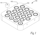
- Fig. 1 schematically illustrates an embodiment of a base device system 100 comprising a base device 101 and a supporting means 102.
- the supporting means 102 is in this embodiment in the form of a solid plate provided with apertures 103.
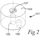
- Fig. 2 shows a an embodiment of a base device 101 having a build surface 104 and being of a generally cylindrical shape.
- the base device further has alignment means 105, 106, in the form of holes for keeping the base device 101 with an additive manufactured object in a correct centered and rotational position in the supporting means.
- a slot 107 is present on the upper side of the base device 101.
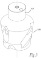
- Fig. 3 shows an embodiment of a base device 101 with an additive manufactured object 108 built on it being a milling tool body prior to post-processing machining.
- Fig. 4 shows an illustration of a base device 101 mounted in a CNC machine spindle 109 via a chuck 110.
- the base device 101 has an additive manufactured object 108 built on it.
- a machining tool 111 is mounted on a machine spindle 112 in the CNC machine.
- the method comprises providing one or more base devices 101 in the form of a substantially cylindrical metal bodies, providing a supporting means in the form of a metal base plate 102 having one or more apertures 103.
- the one or more base devices 101 are then each put into an aperture 103 of the base plate 102 forming a base device system 100.
- the base device system 100 of mounted base devices 101 in the base plate 102 is then put into an additive manufacturing machine, alternatively the base plate 102 is first inserted into the additive manufacturing machine and the base devices 101 then mounted in the base plate apertures 103. Then it is started to build a layer (L) of additive manufactured metal by laser powder-bed fusion followed by the building of the actual objects 108 by continuing using laser powder-bed fusion.
- L layer
- each base device 101 When an object 108 have been built on each base device 101 the whole base device system 100 of the base plate 102 with the mounted base devices 101 is taken out from the additive manufacturing machine and transferred to the location of a CNC machine. The base devices 101 are then one after another mounted in the CNC machine spindle 109 and processed into the final desired shape and surface smoothness. When the processing is finished the object is finally separated from the base device by a machining operation where also the first layer (L) of additive manufactured metal situated under the actual object is removed.
- L first layer
- the base device 101 is preferably in the form of a substantially cylindrical metal body of a total height of between 2 and 10 cm and a diameter of between 1 and 10 cm.
- the supporting means in the form of a metal base plate 102 suitably has from 1 to 50 apertures 103.
- the thickness of the base plate 102 is suitably between 1 and 10 cm, depending on the height of the base devices 101 to be combined with the base plate 102.
- the layer (L) of additive manufactured metal is suitably built to a height of between 1-50 mm.
- the base devices 101 are one after each other taken out from the base plate 102 and put into the CNC machine by a robot. After processing including separation of the post-processed built object from the base plate 102 a robot is taking the object out of the CNC machine and as well the base device 101. The base device 101 is then ready for use again in an additive manufacturing process.
Landscapes
- Engineering & Computer Science (AREA)
- Chemical & Material Sciences (AREA)
- Materials Engineering (AREA)
- Manufacturing & Machinery (AREA)
- Health & Medical Sciences (AREA)
- General Health & Medical Sciences (AREA)
- Toxicology (AREA)
- Powder Metallurgy (AREA)
- Physics & Mathematics (AREA)
- Plasma & Fusion (AREA)
Claims (8)
- Verfahren zur Herstellung eines Metallgegenstandes (108), bei dem ein Gegenstand (108) mit einem additiven Fertigungsverfahren auf einer Basiseinheit (101) aufgebaut wird, die an einem Ende eine Aufbaufläche (104) aufweist und an ihrem der Aufbaufläche (104) gegenüberliegenden Ende ein Verbindungselement aufweist, wobei die Basiseinheit (101) Teil eines Basiseinheitssystems (100) ist, das wenigstens eine Basiseinheit (101) und ein Tragelement (102) enthält, das Verbindungselemente aufweist, die so beschaffen sind, dass sie mit Verbindungselementen an der Basiseinheit (101) in Eingriff gebracht werden können, um die Basiseinheit (101) während des additiven Herstellungsverfahrens in einer stabilen Position zu halten, wobei das Verfahren die folgenden Schritte umfasst:Aufbauen des einen Objekts (108) auf mindestens einem Teil der Basiseinheit-Aufbaufläche (104) mit dem additiven Fertigungsprozess, Entfernen der Basiseinheit (101) von der additiven Fertigungsmaschine durch Entfernen des Basiseinheitssystems (100), während sich die mindestens eine Basiseinheit (101) noch in einer stabilen Position innerhalb des Tragelements (102) befindet, Entfernen der Basiseinheit (101) von dem Tragelement (102), Verbinden der Basiseinheit (101) mit einer CNC-Maschine, die mit mindestens einem Bearbeitungswerkzeug ausgestattet ist, wobei i) die Basiseinheit (101) mittels des Verbindungselements in einer CNC-Maschinenwelle (112) gehalten ist oder ii) über eine CNC-Maschinenschnittstellenkupplung, die in dem Verbindungselement enthalten ist, und Nachbearbeitung des aufgebauten Objekts in der CNC-Maschine vor dem Trennen des aufgebauten Objekts (108) von der Basiseinheit (101) mit Hilfe eines Bearbeitungswerkzeugs (111) in der CNC-Maschine,wobei das Verfahren einen Schritt des Aufbauens einer Schicht (L) aus Metall auf wenigstens einem Teil der Basiseinheit- Aufbaufläche (104) in einem additiven Herstellungsprozess enthält, bevor der erste Teil des Objekts aufgebaut wird, wobei der Schritt des Trennens des aufgebauten Objekts (108) von der Basiseinheit (101) das Entfernen wenigstens eines Teils der Schicht (L) aus Metall auf der Basiseinheit (101) umfasst,wobei ein Teil der Schicht (L) aus Metall nach dem Trennen des aufgebauten Objekts (108) auf der Basiseinheit (101) verbleibt und dieser verbleibende Teil der Schicht (L) aus Metall in einem nachfolgenden Schritt von der Basiseinheit (101) entfernt wird.
- Verfahren nach Anspruch 1, das einen Schritt des Entfernens eines Teils der Basiseinheit (101) umfasst.
- Verfahren nach einem der Ansprüche 1 oder 2, wobei die Metallschicht (L) mittels eines Drehwerkzeugs, eines Fräswerkzeugs, eines Feilwerkzeugs oder eines Sägewerkzeugs oder eines Werkzeugs zum elektroerosiven Bearbeiten entfernt wird.
- Verfahren nach einem der vorhergehenden Ansprüche, das wenigstens einen Schritt der Nachbearbeitung des aufgebauten Objekts (108) in der CNC-Maschine vor der Trennung des Objekts (108) von der Basiseinheit (101) umfasst, wobei die Nachbearbeitung Drehen, Fräsen, Bohren, Strahlen, Schleifen, Finishen, Beschichten, elektroerosives Bearbeiten, Plattieren und Messvorgänge umfasst.
- Verfahren nach Anspruch 1, wobei das Verbindungselement an der Basiseinheit (101) eine CNC-Maschinenschnittstellenkupplung aufweist.
- Verfahren nach einem der vorangehenden Ansprüche, wobei das Tragelement (102) eine massive Platte aufweist, die eine oder mehrere Ausnehmungen oder Öffnungen aufweist.
- Verfahren nach einem der Ansprüche 1 bis 5, wobei das Tragelement einen Halter mit offener Struktur in Form einer Anordnung von Stäben oder Gewinden aufweist.
- Verfahren nach einem der Ansprüche 2 bis 7, wobei das additive Herstellungsverfahren das Laser-Pulverbettschmelzen oder das Pulverbettschmelzen mittels Elektronenstrahl ist.
Priority Applications (4)
| Application Number | Priority Date | Filing Date | Title |
|---|---|---|---|
| EP18167033.2A EP3552738B1 (de) | 2018-04-12 | 2018-04-12 | Verfahren zur herstellung eines generativ gefertigten objekts |
| CN201980025267.7A CN112088059A (zh) | 2018-04-12 | 2019-04-05 | 生产增材制造物体的方法 |
| US17/046,330 US20210146449A1 (en) | 2018-04-12 | 2019-04-05 | Method of producing an additive manufactured object |
| PCT/EP2019/058616 WO2019197281A1 (en) | 2018-04-12 | 2019-04-05 | A method of producing an additive manufactured object |
Applications Claiming Priority (1)
| Application Number | Priority Date | Filing Date | Title |
|---|---|---|---|
| EP18167033.2A EP3552738B1 (de) | 2018-04-12 | 2018-04-12 | Verfahren zur herstellung eines generativ gefertigten objekts |
Publications (3)
| Publication Number | Publication Date |
|---|---|
| EP3552738A1 EP3552738A1 (de) | 2019-10-16 |
| EP3552738C0 EP3552738C0 (de) | 2024-07-31 |
| EP3552738B1 true EP3552738B1 (de) | 2024-07-31 |
Family
ID=61972362
Family Applications (1)
| Application Number | Title | Priority Date | Filing Date |
|---|---|---|---|
| EP18167033.2A Active EP3552738B1 (de) | 2018-04-12 | 2018-04-12 | Verfahren zur herstellung eines generativ gefertigten objekts |
Country Status (4)
| Country | Link |
|---|---|
| US (1) | US20210146449A1 (de) |
| EP (1) | EP3552738B1 (de) |
| CN (1) | CN112088059A (de) |
| WO (1) | WO2019197281A1 (de) |
Families Citing this family (5)
| Publication number | Priority date | Publication date | Assignee | Title |
|---|---|---|---|---|
| CN117601436A (zh) * | 2019-04-09 | 2024-02-27 | 株式会社 尼康 | 造型单元和造型方法、加工单元和加工方法 |
| EP3815840B1 (de) * | 2019-10-31 | 2023-10-04 | Sandvik Machining Solutions AB | Verfahren zur herstellung eines werkzeugteils |
| EP4171926A4 (de) | 2020-06-24 | 2024-06-19 | Vulcanforms Inc. | Plattenmontage in der generativen fertigung |
| CN112857092A (zh) * | 2021-01-18 | 2021-05-28 | 哈电发电设备国家工程研究中心有限公司 | 一种微通道换热器及其加工方法 |
| CN113245562B (zh) * | 2021-06-22 | 2021-10-01 | 北京煜鼎增材制造研究院有限公司 | 高能束制备金属试验件与结构件的设备 |
Citations (1)
| Publication number | Priority date | Publication date | Assignee | Title |
|---|---|---|---|---|
| US20160031010A1 (en) * | 2013-03-05 | 2016-02-04 | United Technologies Corporation | Build platforms for additive manufacturing |
Family Cites Families (10)
| Publication number | Priority date | Publication date | Assignee | Title |
|---|---|---|---|---|
| DE29907262U1 (de) * | 1999-04-23 | 1999-07-15 | Eos Gmbh Electro Optical Systems, 82152 Planegg | Vorrichtung zum Herstellen eines dreidimensionalen Objektes mittels Rapid Prototyping |
| DE102012011217B4 (de) * | 2012-06-06 | 2025-08-21 | Concept Laser Gmbh | Vorrichtung zur Herstellung von dreidimensionalen Bauteilen |
| JP6768633B2 (ja) * | 2014-07-21 | 2020-10-14 | デリニア, インコーポレイテッド | 自己免疫疾患を治療するために調節性t細胞を選択的に活性化する分子 |
| WO2017051029A1 (en) * | 2015-09-25 | 2017-03-30 | Addifab Aps | Additive manufacturing device and system, modular build platform and build platform unit |
| ES2621477B1 (es) * | 2015-12-04 | 2018-06-21 | Instituto Tecnologico Metalmecanico,Mueble,Madera,Embalaje Y Afines | Procedimiento y sistema de precisión para mecanización de piezas obtenidas por fabricación aditiva |
| US20170266890A1 (en) * | 2016-03-15 | 2017-09-21 | Incodema3D, LLC | Additive manufacturing device |
| GB2550855B (en) * | 2016-05-25 | 2019-09-25 | Rolls Royce Plc | Method of manufacture |
| NL2017022B1 (en) * | 2016-06-22 | 2018-01-04 | Additive Ind Bv | Apparatus for producing an object by means of additive manufacturing |
| CN106312066B (zh) * | 2016-09-29 | 2018-08-31 | 首都航天机械公司 | 一种用于激光选区熔化增材制造的组合基板 |
| EP3417961B1 (de) * | 2017-06-19 | 2022-07-27 | General Electric Company | Halterung zur generativen fertigung |
-
2018
- 2018-04-12 EP EP18167033.2A patent/EP3552738B1/de active Active
-
2019
- 2019-04-05 US US17/046,330 patent/US20210146449A1/en active Pending
- 2019-04-05 CN CN201980025267.7A patent/CN112088059A/zh active Pending
- 2019-04-05 WO PCT/EP2019/058616 patent/WO2019197281A1/en not_active Ceased
Patent Citations (1)
| Publication number | Priority date | Publication date | Assignee | Title |
|---|---|---|---|---|
| US20160031010A1 (en) * | 2013-03-05 | 2016-02-04 | United Technologies Corporation | Build platforms for additive manufacturing |
Non-Patent Citations (1)
| Title |
|---|
| THOMPSON MARY KATHRYN ET AL: "Design for Additive Manufacturing: Trends, opportunities, considerations, and constraints", CIRP ANNALS, ELSEVIER BV, NL, CH, FR, vol. 65, no. 2, 25 June 2016 (2016-06-25), pages 737 - 760, XP029690807, ISSN: 0007-8506, DOI: 10.1016/J.CIRP.2016.05.004 * |
Also Published As
| Publication number | Publication date |
|---|---|
| EP3552738C0 (de) | 2024-07-31 |
| CN112088059A (zh) | 2020-12-15 |
| WO2019197281A1 (en) | 2019-10-17 |
| EP3552738A1 (de) | 2019-10-16 |
| US20210146449A1 (en) | 2021-05-20 |
Similar Documents
| Publication | Publication Date | Title |
|---|---|---|
| EP3552738B1 (de) | Verfahren zur herstellung eines generativ gefertigten objekts | |
| EP0827807B1 (de) | Vorrichtung und Verfahren zur Bearbeitung von langen Stangen | |
| KR101002610B1 (ko) | 초경합금 공구를 생산하는 원통 연삭법 및 초경합금 공구의생산시 원통 스타팅 바디를 연삭하는 원통 연삭기 | |
| US6935003B2 (en) | Compound fabrication process and apparatus | |
| CN102753304B (zh) | 滚子的制造方法 | |
| US8739409B2 (en) | Method for dual production of small-scale products | |
| EP3006176B1 (de) | Vorrichtung und verfahren zur formung eines lochs durch eine glasplatte | |
| EP3815840B1 (de) | Verfahren zur herstellung eines werkzeugteils | |
| KR101877501B1 (ko) | 수치제어 공작기계용 입체가공 지그 및 이를 이용한 입체가공방법 | |
| CN112171198B (zh) | 一种栅格结构零件的加工方法 | |
| US20100166519A1 (en) | Clamping method for workpieces used for the production of compressor or turbine wheels | |
| KR102069370B1 (ko) | 이젝트핀 자동 가공 장치 | |
| US5692286A (en) | Method for shaping parts in one or more stacked board shaped elements and machine tool for implementing this method | |
| CN101208176A (zh) | 一种用于机械加工、尤其是用于对轻质合金轮钻孔和车削的方法,以及根据该方法运行的机械加工设备 | |
| US20200114432A1 (en) | Method for assembling a tool system module, and tool system module produced accordingly | |
| JP3513321B2 (ja) | 多面体加工機およびその加工方法 | |
| WO2011103116A2 (en) | Connection element for forming an interface between two parts of a machine tool that can be releasably connected to each other, and method for manufacturing such a connection element | |
| KR101894268B1 (ko) | 피스톤탑코아가이드금형의 절삭가공을 위한 지그 | |
| EP4000771A1 (de) | Verfahren zur herstellung eines artikels auf einer basisvorrichtung | |
| KR102180103B1 (ko) | 언발란스 제품 가공방법 및 가공용 지그 | |
| JPH0639601A (ja) | 薄肉円筒形状ワークの内面加工方法 | |
| CN114474288A (zh) | 一种实木家具组件加工工艺 | |
| JPH077048Y2 (ja) | 旋盤用治具 | |
| CN111604640A (zh) | 金属工件一体式加工工艺 | |
| EP0124121A2 (de) | Verfahren und Lehren zum Einstellen von Werkzeugen für Drehmaschinen |
Legal Events
| Date | Code | Title | Description |
|---|---|---|---|
| PUAI | Public reference made under article 153(3) epc to a published international application that has entered the european phase |
Free format text: ORIGINAL CODE: 0009012 |
|
| STAA | Information on the status of an ep patent application or granted ep patent |
Free format text: STATUS: THE APPLICATION HAS BEEN PUBLISHED |
|
| AK | Designated contracting states |
Kind code of ref document: A1 Designated state(s): AL AT BE BG CH CY CZ DE DK EE ES FI FR GB GR HR HU IE IS IT LI LT LU LV MC MK MT NL NO PL PT RO RS SE SI SK SM TR |
|
| AX | Request for extension of the european patent |
Extension state: BA ME |
|
| STAA | Information on the status of an ep patent application or granted ep patent |
Free format text: STATUS: REQUEST FOR EXAMINATION WAS MADE |
|
| 17P | Request for examination filed |
Effective date: 20200416 |
|
| RBV | Designated contracting states (corrected) |
Designated state(s): AL AT BE BG CH CY CZ DE DK EE ES FI FR GB GR HR HU IE IS IT LI LT LU LV MC MK MT NL NO PL PT RO RS SE SI SK SM TR |
|
| STAA | Information on the status of an ep patent application or granted ep patent |
Free format text: STATUS: EXAMINATION IS IN PROGRESS |
|
| 17Q | First examination report despatched |
Effective date: 20210608 |
|
| RIC1 | Information provided on ipc code assigned before grant |
Ipc: B22F 3/24 20060101ALN20240226BHEP Ipc: B22F 12/82 20210101ALI20240226BHEP Ipc: B22F 12/30 20210101ALI20240226BHEP Ipc: B22F 10/66 20210101ALI20240226BHEP Ipc: B22F 10/47 20210101ALI20240226BHEP Ipc: B22F 10/40 20210101ALI20240226BHEP Ipc: B33Y 40/20 20200101ALI20240226BHEP Ipc: B33Y 40/00 20150101ALI20240226BHEP Ipc: B33Y 30/00 20150101ALI20240226BHEP Ipc: B22F 3/105 20060101AFI20240226BHEP |
|
| GRAP | Despatch of communication of intention to grant a patent |
Free format text: ORIGINAL CODE: EPIDOSNIGR1 |
|
| STAA | Information on the status of an ep patent application or granted ep patent |
Free format text: STATUS: GRANT OF PATENT IS INTENDED |
|
| INTG | Intention to grant announced |
Effective date: 20240409 |
|
| GRAS | Grant fee paid |
Free format text: ORIGINAL CODE: EPIDOSNIGR3 |
|
| GRAA | (expected) grant |
Free format text: ORIGINAL CODE: 0009210 |
|
| STAA | Information on the status of an ep patent application or granted ep patent |
Free format text: STATUS: THE PATENT HAS BEEN GRANTED |
|
| AK | Designated contracting states |
Kind code of ref document: B1 Designated state(s): AL AT BE BG CH CY CZ DE DK EE ES FI FR GB GR HR HU IE IS IT LI LT LU LV MC MK MT NL NO PL PT RO RS SE SI SK SM TR |
|
| REG | Reference to a national code |
Ref country code: CH Ref legal event code: EP Ref country code: GB Ref legal event code: FG4D |
|
| REG | Reference to a national code |
Ref country code: DE Ref legal event code: R096 Ref document number: 602018072374 Country of ref document: DE |
|
| REG | Reference to a national code |
Ref country code: IE Ref legal event code: FG4D |
|
| U01 | Request for unitary effect filed |
Effective date: 20240820 |
|
| U07 | Unitary effect registered |
Designated state(s): AT BE BG DE DK EE FI FR IT LT LU LV MT NL PT RO SE SI Effective date: 20240902 |
|
| PG25 | Lapsed in a contracting state [announced via postgrant information from national office to epo] |
Ref country code: NO Free format text: LAPSE BECAUSE OF FAILURE TO SUBMIT A TRANSLATION OF THE DESCRIPTION OR TO PAY THE FEE WITHIN THE PRESCRIBED TIME-LIMIT Effective date: 20241031 |
|
| PG25 | Lapsed in a contracting state [announced via postgrant information from national office to epo] |
Ref country code: GR Free format text: LAPSE BECAUSE OF FAILURE TO SUBMIT A TRANSLATION OF THE DESCRIPTION OR TO PAY THE FEE WITHIN THE PRESCRIBED TIME-LIMIT Effective date: 20241101 Ref country code: PL Free format text: LAPSE BECAUSE OF FAILURE TO SUBMIT A TRANSLATION OF THE DESCRIPTION OR TO PAY THE FEE WITHIN THE PRESCRIBED TIME-LIMIT Effective date: 20240731 |
|
| PG25 | Lapsed in a contracting state [announced via postgrant information from national office to epo] |
Ref country code: IS Free format text: LAPSE BECAUSE OF FAILURE TO SUBMIT A TRANSLATION OF THE DESCRIPTION OR TO PAY THE FEE WITHIN THE PRESCRIBED TIME-LIMIT Effective date: 20241130 |
|
| PG25 | Lapsed in a contracting state [announced via postgrant information from national office to epo] |
Ref country code: HR Free format text: LAPSE BECAUSE OF FAILURE TO SUBMIT A TRANSLATION OF THE DESCRIPTION OR TO PAY THE FEE WITHIN THE PRESCRIBED TIME-LIMIT Effective date: 20240731 |
|
| PG25 | Lapsed in a contracting state [announced via postgrant information from national office to epo] |
Ref country code: ES Free format text: LAPSE BECAUSE OF FAILURE TO SUBMIT A TRANSLATION OF THE DESCRIPTION OR TO PAY THE FEE WITHIN THE PRESCRIBED TIME-LIMIT Effective date: 20240731 Ref country code: RS Free format text: LAPSE BECAUSE OF FAILURE TO SUBMIT A TRANSLATION OF THE DESCRIPTION OR TO PAY THE FEE WITHIN THE PRESCRIBED TIME-LIMIT Effective date: 20241031 |
|
| PG25 | Lapsed in a contracting state [announced via postgrant information from national office to epo] |
Ref country code: RS Free format text: LAPSE BECAUSE OF FAILURE TO SUBMIT A TRANSLATION OF THE DESCRIPTION OR TO PAY THE FEE WITHIN THE PRESCRIBED TIME-LIMIT Effective date: 20241031 Ref country code: PL Free format text: LAPSE BECAUSE OF FAILURE TO SUBMIT A TRANSLATION OF THE DESCRIPTION OR TO PAY THE FEE WITHIN THE PRESCRIBED TIME-LIMIT Effective date: 20240731 Ref country code: NO Free format text: LAPSE BECAUSE OF FAILURE TO SUBMIT A TRANSLATION OF THE DESCRIPTION OR TO PAY THE FEE WITHIN THE PRESCRIBED TIME-LIMIT Effective date: 20241031 Ref country code: IS Free format text: LAPSE BECAUSE OF FAILURE TO SUBMIT A TRANSLATION OF THE DESCRIPTION OR TO PAY THE FEE WITHIN THE PRESCRIBED TIME-LIMIT Effective date: 20241130 Ref country code: HR Free format text: LAPSE BECAUSE OF FAILURE TO SUBMIT A TRANSLATION OF THE DESCRIPTION OR TO PAY THE FEE WITHIN THE PRESCRIBED TIME-LIMIT Effective date: 20240731 Ref country code: GR Free format text: LAPSE BECAUSE OF FAILURE TO SUBMIT A TRANSLATION OF THE DESCRIPTION OR TO PAY THE FEE WITHIN THE PRESCRIBED TIME-LIMIT Effective date: 20241101 Ref country code: ES Free format text: LAPSE BECAUSE OF FAILURE TO SUBMIT A TRANSLATION OF THE DESCRIPTION OR TO PAY THE FEE WITHIN THE PRESCRIBED TIME-LIMIT Effective date: 20240731 |
|
| PG25 | Lapsed in a contracting state [announced via postgrant information from national office to epo] |
Ref country code: SM Free format text: LAPSE BECAUSE OF FAILURE TO SUBMIT A TRANSLATION OF THE DESCRIPTION OR TO PAY THE FEE WITHIN THE PRESCRIBED TIME-LIMIT Effective date: 20240731 |
|
| PG25 | Lapsed in a contracting state [announced via postgrant information from national office to epo] |
Ref country code: CZ Free format text: LAPSE BECAUSE OF FAILURE TO SUBMIT A TRANSLATION OF THE DESCRIPTION OR TO PAY THE FEE WITHIN THE PRESCRIBED TIME-LIMIT Effective date: 20240731 |
|
| PG25 | Lapsed in a contracting state [announced via postgrant information from national office to epo] |
Ref country code: SK Free format text: LAPSE BECAUSE OF FAILURE TO SUBMIT A TRANSLATION OF THE DESCRIPTION OR TO PAY THE FEE WITHIN THE PRESCRIBED TIME-LIMIT Effective date: 20240731 |
|
| PGFP | Annual fee paid to national office [announced via postgrant information from national office to epo] |
Ref country code: GB Payment date: 20250306 Year of fee payment: 8 |
|
| U20 | Renewal fee for the european patent with unitary effect paid |
Year of fee payment: 8 Effective date: 20250430 |
|
| PLBE | No opposition filed within time limit |
Free format text: ORIGINAL CODE: 0009261 |
|
| STAA | Information on the status of an ep patent application or granted ep patent |
Free format text: STATUS: NO OPPOSITION FILED WITHIN TIME LIMIT |
|
| 26N | No opposition filed |
Effective date: 20250501 |
|
| REG | Reference to a national code |
Ref country code: CH Ref legal event code: H13 Free format text: ST27 STATUS EVENT CODE: U-0-0-H10-H13 (AS PROVIDED BY THE NATIONAL OFFICE) Effective date: 20251125 |
|
| PG25 | Lapsed in a contracting state [announced via postgrant information from national office to epo] |
Ref country code: MC Free format text: LAPSE BECAUSE OF FAILURE TO SUBMIT A TRANSLATION OF THE DESCRIPTION OR TO PAY THE FEE WITHIN THE PRESCRIBED TIME-LIMIT Effective date: 20240731 |
|
| PG25 | Lapsed in a contracting state [announced via postgrant information from national office to epo] |
Ref country code: CH Free format text: LAPSE BECAUSE OF NON-PAYMENT OF DUE FEES Effective date: 20250430 |