EP3552709A1 - Roller mill - Google Patents
Roller mill Download PDFInfo
- Publication number
- EP3552709A1 EP3552709A1 EP18166249.5A EP18166249A EP3552709A1 EP 3552709 A1 EP3552709 A1 EP 3552709A1 EP 18166249 A EP18166249 A EP 18166249A EP 3552709 A1 EP3552709 A1 EP 3552709A1
- Authority
- EP
- European Patent Office
- Prior art keywords
- overload
- threaded portion
- longitudinal direction
- roller
- roll mill
- Prior art date
- Legal status (The legal status is an assumption and is not a legal conclusion. Google has not performed a legal analysis and makes no representation as to the accuracy of the status listed.)
- Withdrawn
Links
Images


Classifications
-
- B—PERFORMING OPERATIONS; TRANSPORTING
- B02—CRUSHING, PULVERISING, OR DISINTEGRATING; PREPARATORY TREATMENT OF GRAIN FOR MILLING
- B02C—CRUSHING, PULVERISING, OR DISINTEGRATING IN GENERAL; MILLING GRAIN
- B02C4/00—Crushing or disintegrating by roller mills
- B02C4/28—Details
- B02C4/32—Adjusting, applying pressure to, or controlling the distance between, milling members
Definitions
- the invention relates to a roller mill with the features according to the preamble of claim 1.
- a roller mill In the heavy clay industry, roll mills are used for processing clays.
- a roller mill comprises two rollers which are rotatably mounted. The two rollers are arranged at a distance from one another, so that a gap is formed between them.
- the two rollers are driven in opposite directions to rotational movements.
- the coarse raw material In the gap between the rolls, the coarse raw material is ground to a grain size of up to 0.5 mm. Due to the resulting wear of the surfaces of the rollers they must be smoothly pulled regularly. This reduces the diameter of a roller continuously.
- the width of the gap between the two rolls is of crucial importance.
- the rocker has two opposite in the direction perpendicular to the pivot axis of the rocker arms. At the end remote from the pivot axis of the first arm a stop element of the first arm is arranged. At the end remote from the pivot axis of the second boom attacks the overload protection.
- the overload protection comprises a biased by a stop spring element.
- the spring element acts on the nut element in the longitudinal direction. Due to the interplay of the spring element of the overload protection and the nut element of the adjusting element, the first roller of the roller mill can easily avoid overloading and increase the gap between the first roller and the second roller.
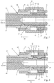
- a safety shoulder 34 of the operating element 30 has a fifth distance a5 measured in the longitudinal direction 100 relative to the overload shoulder 61.
- the safety shoulder 34 faces away from the connecting element 34.
- the safety shoulder 34 has a distance to the axis 101, which is at least as large as the distance of the pressure element 8 to the axis 101.
- the fifth distance a5 is smaller than the third distance a3.
- the fifth distance a5 is smaller than the fourth distance a4.
Landscapes
- Engineering & Computer Science (AREA)
- Food Science & Technology (AREA)
- Transmission Devices (AREA)
Abstract
Die Erfindung betrifft eine Walzenmühle (1) zum Mahlen grobkeramischer Materialien, die eine erste drehbar gelagerte Walze (3), eine zweite drehbar gelagerte Walze (4), ein Verstellelement (5) und eine Überlastsicherung (6) umfasst. Zwischen der ersten Walze (3) und der zweiten Walze (4) ist ein Spalt (2) ausgebildet ist, in dem das grobkeramische Material gemahlen wird. Mit dem Verstellelement (5) ist eine Einstellung einer Breite (B) des Spalts (2) möglich. Die Überlastsicherung (6) ermöglicht bei Überschreitung eines Schwellwerts einer auf die Walzen (3, 4) wirkenden Kraft (F1) in Richtung einer Spaltverbreiterung eine Vergrößerung der Breite (B) des Spalts (2). Das Verstellelement (5) ist mit der ersten Walze (3) verbunden und erstreckt sich in einer Längsrichtung (100). Die Überlastsicherung (6) ist mit dem Verstellelement (5) in Reihe geschaltet.The invention relates to a roller mill (1) for grinding coarse ceramic materials, which comprises a first rotatably mounted roller (3), a second rotatably mounted roller (4), an adjusting element (5) and an overload protection device (6). A gap (2), in which the coarse ceramic material is ground, is formed between the first roller (3) and the second roller (4). The adjustment element (5) can be used to set a width (B) of the gap (2). The overload protection device (6) enables the width (B) of the gap (2) to be increased in the direction of a widening of the gap when a threshold value of a force (F1) acting on the rollers (3, 4) is exceeded. The adjusting element (5) is connected to the first roller (3) and extends in a longitudinal direction (100). The overload protection device (6) is connected in series with the adjustment element (5).
Description
Die Erfindung betrifft eine Walzenmühle mit den Merkmalen nach dem Oberbegriff des Anspruchs 1.The invention relates to a roller mill with the features according to the preamble of claim 1.
In der grobkeramischen Industrie werden Walzenmühlen zum Aufbereiten von Tonen verwendet. Hierzu umfasst eine Walzenmühle zwei Walzen, die drehbar gelagert sind. Die beiden Walzen sind in einem Abstand zueinander angeordnet, so dass zwischen ihnen ein Spalt ausgebildet ist. Im Betrieb der Walzenmühle werden die beiden Walzen gegenläufig zu Drehbewegungen angetrieben. Im Spalt zwischen den Walzen wird das grobe Rohmaterial auf eine Körnung von bis zu 0,5 mm gemahlen. Durch den dabei entstehenden Verschleiß der Oberflächen der Walzen müssen diese regelmäßig glatt gezogen werden. Dadurch verringert sich der Durchmesser einer Walze kontinuierlich. Für die Körnungsfeinheit des gemahlenen Tons ist die Breite des Spalts zwischen den beiden Walzen von entscheidender Bedeutung.In the heavy clay industry, roll mills are used for processing clays. For this purpose, a roller mill comprises two rollers which are rotatably mounted. The two rollers are arranged at a distance from one another, so that a gap is formed between them. During operation of the roller mill, the two rollers are driven in opposite directions to rotational movements. In the gap between the rolls, the coarse raw material is ground to a grain size of up to 0.5 mm. Due to the resulting wear of the surfaces of the rollers they must be smoothly pulled regularly. This reduces the diameter of a roller continuously. For the grain fineness of the milled clay, the width of the gap between the two rolls is of crucial importance.
Um die Breite des Spalts zwischen den Walzen über die gesamte Lebensdauer beider Walzen konstant zu halten, muss mindestens eine Walze zur anderen angenähert werden. Zu diesem Zweck ist eine der beiden Walzen, die sogenannte Loswalze, in einer Schwinge gelagert. Durch Verschwenken der Schwinge um ihre Schwenkachse ist die Breite des Spalts einstellbar.In order to keep the width of the gap between the rolls constant over the entire life of both rolls, at least one roll must be approximated to the other. For this purpose, one of the two rollers, the so-called Loswalze, stored in a rocker. By pivoting the rocker about its pivot axis, the width of the gap is adjustable.
Um eine Zerstörung der Walzenmühle beim Passieren von Fremdkörpern durch den Spalt zu vermeiden, besitzt die Schwinge eine Überlastsicherung. Die Überlastsicherung gewährleistet, dass die Loswalze bei Überschreitung eines Schwellwerts einer auf die Loswalze wirkenden Kraft in Richtung einer Spaltverbreiterung eine widerstandsarme Vergrößerung der Breite des Spalts ermöglicht. Ein solcher Überlastfall tritt beispielsweise ein, wenn ein hartes Objekt grobkeramischen Materials, dessen Durchmesser signifikant größer als die Spaltbreite ist, durch die sich drehenden Walzen in den Spalt getrieben wird. Die Überlastsicherung sorgt in diesem Überlastfall dafür, dass die Loswalze möglichst schnell ausweichen kann und anschließend wieder in die Ursprungsposition zurückkehrt.In order to avoid destruction of the roller mill when passing foreign bodies through the gap, the rocker has an overload protection. The overload protection ensures that the loose roller when exceeding a threshold value of a force acting on the Loswalze force in the direction of a gap broadening allows a low-resistance increase in the width of the gap. Such an overload case occurs, for example, when a hard object of coarse ceramic material whose diameter is significantly larger than the gap width is driven into the gap by the rotating rollers. The overload protection ensures in this case of overload that the Loswalze can avoid as quickly as possible and then returns to the original position.
Im Stand der Technik besitzt die Schwinge zwei sich in Richtung senkrecht zur Schwenkachse der Schwinge gegenüberliegende Ausleger. Am der Schwenkachse abgewandten Ende des ersten Auslegers ist ein Anschlagelement des ersten Auslegers angeordnet. Am der Schwenkachse abgewandten Ende des zweiten Auslegers greift die Überlastsicherung an.In the prior art, the rocker has two opposite in the direction perpendicular to the pivot axis of the rocker arms. At the end remote from the pivot axis of the first arm a stop element of the first arm is arranged. At the end remote from the pivot axis of the second boom attacks the overload protection.
Für die Einstellung der Spaltbreite wird als Einstellelement eine Spindel verwendet, die einen Anschlag für das Anschlagelement am ersten Ausleger der Schwinge bewegen kann. Durch Verstellen des Anschlags wird die Schwinge um ihre Schwenkachse verschwenkt, und dabei wird die Position der Drehachse der Loswalze verändert. Dies bewirkt eine Veränderung der Spaltbreite zwischen den Walzen.For setting the gap width, a spindle is used as adjusting, which can move a stop for the stop element on the first arm of the rocker. By adjusting the stop the rocker is pivoted about its pivot axis, and thereby the position of the axis of rotation of the Loswalze is changed. This causes a change in the gap width between the rollers.
Die Überlastsicherung ist in Form eines Hydraulikzylinders separat vom Einstellelement ausgebildet. Die Schwinge ist so angeordnet, dass das Gewicht der Loswalze und des zweiten Auslegers auf dem Hydraulikzylinder lasten. Der Hydraulikzylinder drückt das Ende des zweiten Auslegers mit einem definierten Druck derart in eine Umfangsrichtung der Schwenkachse der Schwinge, dass das Anschlagelement des ersten Auslegers gegen den verstellbaren Anschlag gepresst wird. Dadurch ist die Position der Drehachse der Loswalze bestimmt. Da die der Loswalze gegenüberliegende Drehachse der anderen Walze ortsfest ist, ist somit auch die Breite des Spalts zwischen den Walzen definiert.The overload protection is formed in the form of a hydraulic cylinder separately from the adjustment. The rocker is arranged so that the weight of the idler roller and the second boom load on the hydraulic cylinder. The hydraulic cylinder presses the end of the second arm with a defined pressure in a circumferential direction of the pivot axis of the rocker so that the abutment element of the first arm is pressed against the adjustable stop. As a result, the position of the axis of rotation of the Loswalze is determined. As opposed to the Loswalze Is the axis of rotation of the other roller is stationary, thus the width of the gap between the rollers is defined.
Das Hydrauliksystem ist mit einem Blasenspeicher versehen, der bei einer Überlast den Systemdruck abbaut. Hierdurch sind die Hydraulikzylinder im Überlastfall druckfrei. Dann wird das Ende des zweiten Auslegers nicht mehr in Umfangsrichtung der Schwenkachse der Schwinge gedrückt, und das Gewicht der Loswalze und des zweiten Auslegers bewirken eine Verschwenkung der Schwinge entgegen der Umfangsrichtung der Schwenkachse. Hierbei löst sich das Anschlagelement des ersten Auslegers vom verstellbaren Anschlag, und die Drehachse der Loswalze wird von der Drehachse der anderen Walze entfernt. Die Breite des Spalts wird vergrößert und ein zu großes grobkeramisches Objekt kann den Spalt passieren, ohne dass die Walzen größeren Schaden nehmen.The hydraulic system is equipped with a bladder accumulator, which relieves the system pressure in the event of an overload. As a result, the hydraulic cylinders are pressure-free in case of overload. Then, the end of the second boom is no longer pressed in the circumferential direction of the pivot axis of the rocker, and the weight of the idler roller and the second boom cause a pivoting of the rocker against the circumferential direction of the pivot axis. In this case, the stop element of the first arm releases from the adjustable stop, and the axis of rotation of the Loswalze is removed from the axis of rotation of the other roller. The width of the gap is increased and too large a coarse ceramic object can pass through the gap without the rolls taking much damage.
Die Walzenmühle nach dem Stand der Technik weist den Nachteil auf, dass sehr viele Bauteile und Material für ihre Konstruktion erforderlich sind. Zur Gewährleistung der Überlastfunktion sind zwei Ausleger der Schwinge und ein Hydraulikzylinder mit Blasenspeicher erforderlich. Hierdurch wird die Konstruktion der Walzenmühle aufwendig und kostenintensiv.The prior art roller mill has the disadvantage that many components and material are required for its construction. To ensure the overload function, two arms of the rocker and a hydraulic cylinder with bladder accumulator are required. As a result, the construction of the roller mill is complicated and costly.
Der Erfindung liegt die Aufgabe zugrunde, eine gattungsgemäße Walzenmühle derart weiterzubilden, dass sie mit weniger Bauteilen und Material konstruiert werden kann.The invention has the object of developing a generic roller mill such that it can be constructed with fewer components and material.
Diese Aufgabe wird durch eine Walzenmühle mit den Merkmalen des Anspruchs 1 gelöst.This object is achieved by a roller mill with the features of claim 1.
Bei einer erfindungsgemäßen Walzenmühle ist die Überlastsicherung mit dem Verstellelement in Reihe geschaltet. Falls für die Konstruktion der Walzenmühle eine Schwinge verwendet wird, ist für die Schwinge lediglich ein Ausleger erforderlich. Auf einen Anschlag für diesen Arm kann ebenfalls verzichtet werden. Dadurch können Material und Bauvolumen eingespart werden.In a roll mill according to the invention, the overload protection is connected in series with the adjusting element. If for the construction of the roller mill, a rocker is used, only one boom is required for the rocker. On a stop for this arm can also be dispensed with. As a result, material and volume can be saved.
Vorteilhaft umfasst das Verstellelement einen sich in Längsrichtung erstreckenden Schaft mit einem ersten Gewindeabschnitt und ein Mutterelement mit einem zweiten Gewindeabschnitt. Der Schaft ist gegenüber dem Mutterelement in Längsrichtung über ein Zusammenwirken des ersten Gewindeabschnitts und des zweiten Gewindeabschnitts verstellbar. Dadurch ist die Länge des Verstellelements in Längsrichtung einfach einstellbar.Advantageously, the adjusting element comprises a longitudinally extending shank having a first threaded portion and a nut member having a second threaded portion. The shaft is adjustable relative to the nut member in the longitudinal direction via an interaction of the first threaded portion and the second threaded portion. As a result, the length of the adjusting element in the longitudinal direction is easily adjustable.
Zweckmäßig umfasst die Überlastsicherung ein durch einen Anschlag vorgespanntes Federelement. Das Federelement wirkt auf das Mutterelement in Längsrichtung. Durch das Zusammenspiel des Federelements der Überlastsicherung und des Mutterelements des Verstellelements kann die erste Walze der Walzenmühle auf einfache Weise im Überlastfall ausweichen und den Spalt zwischen der ersten Walze und der zweiten Walze vergrößern.Suitably, the overload protection comprises a biased by a stop spring element. The spring element acts on the nut element in the longitudinal direction. Due to the interplay of the spring element of the overload protection and the nut element of the adjusting element, the first roller of the roller mill can easily avoid overloading and increase the gap between the first roller and the second roller.
In vorteilhafter Weiterbildung der Erfindung umfasst die Überlastsicherung ein Gehäuse. Dadurch kann das Federelement geschützt untergebracht werden. Der Anschlag ist an dem Gehäuse der Überlastsicherung festgelegt. Dadurch werden Bauteile und Bauvolumen eingespart.In an advantageous embodiment of the invention, the overload protection comprises a housing. As a result, the spring element can be accommodated protected. The stop is fixed to the housing of the overload protection. This saves components and construction volume.
In vorteilhafter Weiterbildung der Erfindung umfasst die Überlastsicherung ein separat vom Mutterelement ausgebildetes Druckelement. Das Federelement drückt das Druckelement gegen den Anschlag. Das Federelement drückt das Mutterelement über das Druckelement in einer Kraftrichtung auf die erste Walze. Die Überlastsicherung umfasst eine Überlastschulter. Die Überlastschulter ist an einem Grundkörper des Mutterelements festgelegt. Das Mutterelement umfasst die Überlastschulter. Das Mutterelement stützt sich in Längsrichtung in Richtung auf die Überlastsicherung über die Überlastschulter am Druckelement ab. Das Mutterelement ist so ausgelegt, dass die Überlastschulter bei Überschreitung eines weiteren Schwellwerts einer in Längsrichtung in Richtung auf die Überlastsicherung auf die Überlastschulter wirkenden Kraft vom Grundkörper des Mutterelements abbricht. Dadurch kann eine zweite Sicherheitsstufe für einen Überlastfall geschaffen werden. Beispielsweise kann vorgesehen sein, dass bei Einwirkung einer ersten Kraft auf die erste Walze im Rahmen einer ersten Sicherheitsstufe das Federelement nachgibt. Im Rahmen einer zweiten Sicherheitsstufe kann vorgesehen sein, dass bei Einwirkung einer zweiten, größeren Kraft auf die erste Walze die Überlastschulter vom Grundkörper des Mutterelements abbricht. Dadurch stützt sich der Grundkörper des Mutterelements nicht mehr in Längsrichtung in Richtung auf das Federelement über die Überlastschulter am Druckelement ab, und das Federelement überträgt keine Kraft mehr über die Überlastschulter auf das Mutterelement, bzw. den Grundkörper des Mutterelements. Dadurch kann der Spalt zwischen der ersten Walze und der zweiten Walze noch größer als in der ersten Sicherheitsstufe werden.In an advantageous development of the invention, the overload safety device comprises a pressure element formed separately from the nut element. The spring element presses the pressure element against the stop. The spring element presses the nut element over the pressure element in a direction of force on the first roller. The overload protection includes an overload shoulder. The overload shoulder is fixed to a main body of the nut member. The nut member includes the overload shoulder. The nut member is supported in the longitudinal direction in the direction of the overload protection on the Overload shoulder on the pressure element from. The nut member is designed so that the overload shoulder breaks off when exceeding a further threshold of a force acting in the longitudinal direction in the direction of the overload protection on the overload shoulder force from the main body of the nut member. As a result, a second security level for an overload case can be created. For example, it can be provided that upon application of a first force to the first roller as part of a first security level, the spring element yields. As part of a second level of security can be provided that upon application of a second, larger force on the first roller, the overload shoulder breaks off from the main body of the nut member. As a result, the main body of the nut member is no longer supported in the longitudinal direction in the direction of the spring element via the overload shoulder on the pressure element, and the spring element no longer transfers power via the overload shoulder on the nut member, or the main body of the nut member. As a result, the gap between the first roller and the second roller can be even greater than in the first safety level.
Zweckmäßig ist ein senkrecht zur Längsrichtung gemessener größter Außendurchmesser des Mutterelements kleiner als ein senkrecht zur Längsrichtung gemessener kleinster Innendurchmesser des Druckelements. Ein in Längsrichtung in Richtung auf das Druckelement gemessener erster Abstand zwischen der Überlastschulter und einem Rand des Mutterelements ist kleiner als ein in Längsrichtung in Richtung auf das Druckelement gemessener zweiter Abstand zwischen der Überlastschulter und einem Rand des Druckelements. Dadurch ist ein Raum im Inneren des Druckelements geschaffen, in den das Mutterelement im Überlastfall bei einem Abbrechen der Überlastschultern ausweichen kann. Dadurch steht eine Wegstrecke zur Verfügung, um die ein Abstützarm, der Verstellelement und Überlastsicherung umfasst, im Überlastfall verkürzt werden kann. Durch eine solche Verkürzung kann der Spalt zwischen der ersten Walze und der zweiten Walze im Überlastfall noch größer werden.Suitably, a measured perpendicular to the longitudinal direction largest outer diameter of the nut member is smaller than a measured perpendicular to the longitudinal direction of the smallest inner diameter of the pressure element. A measured in the longitudinal direction in the direction of the pressure element first distance between the overload shoulder and an edge of the nut member is smaller than a measured in the longitudinal direction in the direction of the pressure element second distance between the overload shoulder and an edge of the pressure element. As a result, a space is created in the interior of the pressure element, in which the mother element can escape in case of overload in a break off the overload shoulders. As a result, a distance is available, around which a support arm, the adjustment and overload protection, can be shortened in case of overload. Such a shortening of the gap between the first roller and the second roller in case of overload can be even greater.
In vorteilhafter Weiterbildung der Erfindung umfasst das Verstellelement ein Bedienelement mit einem dritten Gewindeabschnitt, über den das Bedienelement mit dem ersten Gewindeabschnitt des Schafts verbunden ist. Der zweite Gewindeabschnitt des Mutterelements und der dritte Gewindeabschnitt des Bedienelements sind in Längsrichtung nebeneinander angeordnet. Der zweite Gewindeabschnitt und der dritte Gewindeabschnitt sind über eine Mitnehmerverbindung derart miteinander verbunden, dass eine Drehung des dritten Gewindeabschnitts eine Drehung des zweiten Gewindeabschnitts zur Folge hat. Dadurch kann das Mutterelement über das Bedienelement bedient werden. So ist eine Verdrehung des Mutterelements gegenüber dem Schaft durch ein in Längsrichtung entfernt vom Mutterelement angeordnetes Bedienelement möglich.In an advantageous embodiment of the invention, the adjusting element comprises an operating element with a third threaded portion, via which the operating element with the first threaded portion of the shaft is connected. The second threaded portion of the nut member and the third threaded portion of the operating element are arranged side by side in the longitudinal direction. The second threaded portion and the third threaded portion are connected to each other via a driver connection such that rotation of the third threaded portion results in rotation of the second threaded portion. As a result, the nut element can be operated via the operating element. Thus, a rotation of the nut member relative to the shaft by a longitudinally remote from the nut member arranged control element is possible.
Zweckmäßig besitzt das Bedienelement einen frei zugänglichen Werkzeugansatz. Dadurch kann das Bedienelement auf einfache Weise bedient werden.Suitably, the control has a freely accessible tool approach. This allows the control to be operated in a simple manner.
In vorteilhafter Weiterbildung der Erfindung sind der zweite Gewindeabschnitt und der dritte Gewindeabschnitt über die Mitnehmerverbindung derart miteinander verbunden, dass eine Relativbewegung des dritten Gewindeabschnitts und des zweiten Gewindeabschnitts gegeneinander in Längsrichtung möglich ist. Zwischen dem Bedienelement und dem Mutterelement ist in Längsrichtung ein Klemmspalt ausgebildet. Das Verstellelement umfasst ein Klemmelement, mittels dessen der zweite Gewindeabschnitt und der dritte Gewindeabschnitt in Längsrichtung aufeinander zu gedrückt werden können. Dadurch kann das Spiel zwischen dem Gewinde des ersten Gewindeabschnitts des Schafts und dem Gewinde des zweiten Gewindeabschnitts des Mutterelements minimiert werden. Außerdem kann das Mutterelement so gegen eine Bewegung relativ zum Schaft gesichert werden. Dies ist insbesondere im Betrieb der Walzenmühle von Vorteil.In an advantageous embodiment of the invention, the second threaded portion and the third threaded portion via the driver connection are connected to each other such that a relative movement of the third threaded portion and the second threaded portion against each other in the longitudinal direction is possible. Between the control element and the nut element, a clamping gap is formed in the longitudinal direction. The adjusting element comprises a clamping element, by means of which the second threaded portion and the third threaded portion can be pressed towards each other in the longitudinal direction. Thereby, the play between the threads of the first threaded portion of the shaft and the threads of the second threaded portion of the nut member can be minimized. In addition, the nut member can be secured against movement relative to the shaft. This is particularly advantageous in the operation of the roll mill.
Vorteilhaft weist das Klemmelement einen vierten Gewindeabschnitt auf, der mit einem fünften Gewindeabschnitt des Mutterelements zusammenwirkt. Das Klemmelement weist eine Anschlagsfläche für den Anschlag an einer Anschlagsschulter des Bedienelements auf. Dadurch können durch einfaches Aufschrauben des Klemmelements der zweite Gewindeabschnitt und der dritte Gewindeabschnitt in Längsrichtung aufeinander zu gedrückt werden. Das Klemmelement kann so angeordnet werden, dass es leicht von außen zugänglich und bedienbar ist.Advantageously, the clamping element on a fourth threaded portion, which cooperates with a fifth threaded portion of the nut member. The clamping element has a stop surface for the stop on a stop shoulder of the operating element. As a result, by simply screwing the clamping element of the second threaded portion and the third threaded portion are pressed toward each other in the longitudinal direction. The clamping element can be arranged so that it is easily accessible and operable from the outside.
Zweckmäßig ist die Mitnehmerverbindung eine Nut-Passfeder-Verbindung. Die Mitnehmerverbindung kann aber auch als Stiftverbindung oder als Klauenverbindung ausgebildet sein.Suitably, the driver connection is a tongue and groove connection. The driver connection can also be designed as a pin connection or as a claw connection.
Vorteilhaft weist die Überlastsicherung eine sich in Längsrichtung erstreckende Führungsstange auf. Der Schaft ist mittels der Führungsstange geführt. Dadurch ist der Schaft stabil in Längsrichtung geführt. Eine Relativbewegung zwischen Verstellelement und Überlastsicherung ist so in Längsrichtung auf stabile Weise möglich.Advantageously, the overload protection on a longitudinally extending guide rod. The shaft is guided by means of the guide rod. As a result, the shaft is stably guided in the longitudinal direction. A relative movement between adjusting and overload protection is possible in the longitudinal direction in a stable manner.
Zweckmäßig ist das Federelement ein Tellerfederpaket.Suitably, the spring element is a cup spring package.
Vorteilhaft ist die Führungsstange durch das Tellerfederpaket geführt. Dadurch wird Bauvolumen eingespart.Advantageously, the guide rod is guided by the plate spring package. This saves construction volume.
Ein Ausführungsbeispiel der Erfindung ist nachstehend anhand der Zeichnung näher erläutert. Es zeigen:
- Fig. 1
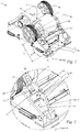
- in einer schematischen Perspektivdarstellung eine erfindungsgemäße Walzenmühle,
- Fig. 2
- in einer vergrößerten Darstellung das in
Fig. 1 mit II gekennzeichnete Detail, das die Baueinheit aus Überlastsicherung und Verstellelement der Walzenmühle zeigt, - Fig. 3
- in einer Ansicht von oben in Längsrichtung des Verstellelements die Baueinheit aus Überlastsicherung und Verstellelement mit einem Teilschnitt durch Schaft und Führungsstange der Baueinheit,
- Fig. 4
- in einer Schnittdarstellung gemäß der in
Fig. 3 mit VI gekennzeichneten Schnittfläche die Baueinheit ausFig. 3 , - Fig. 5
- in einer schematischen, vergrößerten Schnittdarstellung das Detail der Baueinheit nach
Fig. 4 in einem ersten Überlastfall, - Fig. 6
- in einer schematischen, vergrößerten Schnittdarstellung das Detail der Baueinheit nach
Fig. 4 in einem zweiten Überlastfall, - Fig. 7
- in einer schematischen, vergrößerten Darstellung ein Detail aus
Fig. 4 , das das Zusammenwirken zwischen Bedienelement, Mutterelement und Schaft betrifft und - Fig. 8
- die Darstellung nach
Fig. 5 mit übertrieben dargestellter Vergrößerung des ersten, zweiten und dritten Gewindeabschnitts, wobei die Darstellung das Zusammenwirken zwischen Klemmelement, Bedienelement und Mutterelement betrifft.
- Fig. 1
- in a schematic perspective view of a roll mill according to the invention,
- Fig. 2
- in an enlarged view the in
Fig. 1 with II marked detail showing the assembly of overload protection and adjustment of the roll mill, - Fig. 3
- in a view from above in the longitudinal direction of the adjusting element, the assembly of overload protection and adjustment with a partial section through the shaft and guide rod of the unit,
- Fig. 4
- in a sectional view according to the in
Fig. 3 marked with VI cut surface of the unitFig. 3 . - Fig. 5
- in a schematic, enlarged sectional view of the detail of the assembly
Fig. 4 in a first overload case, - Fig. 6
- in a schematic, enlarged sectional view of the detail of the assembly
Fig. 4 in a second overload case, - Fig. 7
- in a schematic, enlarged view of a detail
Fig. 4 , which relates to the interaction between the operating element, nut element and shaft and - Fig. 8
- the representation after
Fig. 5 with exaggerated magnification of the first, second and third threaded portions, the illustration relating to the interaction between the clamping element, operating element and nut element.
Im Betrieb der Walzenmühle 1 werden die beiden Walzen 3, 4 zu gegenläufigen Drehungen um ihre Drehachsen 70, 80 angetrieben. Auf diese Weise wird grobkeramisches Material, das von oben in die Walzenmühle 1 eingebracht wird, von den Drehbewegungen der beiden Walzen 3, 4 in Richtung des Spalts 2 gezogen und durch den Spalt 2 gedrückt. Hierbei wird das grobkeramische Material, beispielsweise Ton, gemahlen. Die Breite B des Spalts 2 bestimmt die Feinheit der Körnung des gemahlenen, grobkeramischen Materials.In operation, the roller mill 1, the two
Zur Verstellung der Breite B des Spalts 2 ist die erste Walze 3 als Loswalze ausgebildet. Die Position der Drehachse 70 der ersten Walze 3 kann mittels eines Verstellelements 5 in Richtung senkrecht zur Drehachse 70 verändert werden. Dabei ändert sich die Breite B des Spalts 2. Die erste Walze 3 ist in einer Achslagerung 66 drehbar gelagert. Die Drehachse 70 der ersten Walze 3 verläuft senkrecht zur Achslagerung 66. Die Achslagerung 66 weist eine Verbindungsstelle 67 zur Verbindung der Achslagerung 66 mit dem Verstellelement 5 auf. Im Ausführungsbeispiel ist die Verbindungsstelle 67 an einer der zweiten Walze 4 abgewandten Seite der Achslagerung 66 angeordnet. Die Verbindungsstelle 67 ist im Ausführungsbeispiel unterhalb der Drehachse 70 der ersten Walze 3 angeordnet. Die Achslagerung 66 ist um eine nicht dargestellte Schwenkachse verschwenkbar. Die Schwenkachse verläuft parallel zu den beiden Drehachsen 70, 80 der Walzen 3, 4. Im Ausführungsbeispiel ist die Schwenkachse unterhalb einer Ebene angeordnet, in der die Drehachse 70 der ersten Walze 3 und die Drehachse 80 der zweiten Walze 4 liegen. Das Verstellelement 5 erstreckt sich in einer Längsrichtung 100. Eine sich in Längsrichtung 100 erstreckende Achse 101 weist einen Abstand zur Schwenkachse der Achslagerung 66 auf. Die Längsachse 101 erstreckt sich in einer Ebene senkrecht zur Schwenkachse der Achslagerung 66. Folglich erstreckt sich die Längsachse 101 in einer Ebene senkrecht zur Drehachse 70 der ersten Walze 3.To adjust the width B of the
Zur Veränderung der Breite B des Spalts 2 greift das Verstellelement 5 an der Verbindungsstelle 67 der Achslagerung 66 an und verschwenkt die Verbindungsstelle 67 um die Schwenkachse der Achslagerung 66. Hierbei wird der Abstand der Drehachse 70 der ersten Walze 3 und der Drehachse 80 der zweiten Walze 4 verändert. In der Folge ändert sich auch die Breite B des Spalts 2. Es kann aber auch vorgesehen sein, dass die Achslagerung nicht verschwenkbar ist. In diesem Fall wird die Achslagerung linear vom Verstellelement verschoben und auf diese Weise eine Veränderung der Breite des Spalts bewirkt.To change the width B of the
Die Walzenmühle 1 umfasst eine Überlastsicherung 6. Die Überlastsicherung 6 ist in Reihe mit dem Verstellelement 5 geschaltet. Die Überlastsicherung 6 wirkt in Reihe mit dem Verstellelement 5. Die Überlastsicherung 6 erstreckt sich in Längsrichtung 100 des Verstellelements 5. Sowohl das Verstellelement 5 als auch die Überlastsicherung 6 wirken in Längsrichtung 100. Das Verstellelement 5 ist in Längsrichtung 100 längenverstellbar. Es nimmt aufgrund der oben schon erwähnten Reihenschaltung ebenso wie die koaxial dazu angeordnete Überlastsicherung 6 Kräfte in Längsrichtung 100 auf. Das Verstellelement 5 ist in Längsrichtung 100 benachbart zur Überlastsicherung 6 angeordnet. Das Verstellelement 5 grenzt an die Überlastsicherung 6 an. Im Ausführungsbeispiel sind das Verstellelement 5 und die Überlastsicherung 6 Teil einer Baueinheit 50.The roller mill 1 comprises an
Im Überlastfall wirkt auf die erste Walze 1 eine erste Kraft F1 in Richtung einer Vergrößerung der Breite B des Spalts 2. Dies ist beispielsweise der Fall, wenn ein Objekt grobkeramischen Materials, das in den Spalt 2 gezogen wird, einen Durchmesser aufweist, der größer als die Breite B des Spalts 2 ist und wenn das Objekt so hart ist, dass es sich beim Durchgang durch den Spalt nicht zerkleinern lässt. Die im Überlastfall wirkende erste Kraft F1 ist größer als ein vorgegebener Schwellwert. Die Überlastsicherung 6 erlaubt bei Überschreiten dieses Schwellwerts eine Vergrößerung der Breite B des Spalts 2. Dadurch kann die erste Walze 3 in Richtung weg von der zweiten Walze 4 ausweichen. Dadurch kann eine Beschädigung der Oberflächen der Walzen 3, 4 vermieden werden. Im Überlastfall wird eine in Längsrichtung 100 gemessene Länge L der Baueinheit 50 verkürzt.In the event of overload, a first force F1 acts on the first roller 1 in the direction of increasing the width B of the
Das Verstellelement 5 umfasst ein Bedienelement 30. Mit dem Bedienelement 30 kann die Länge des Verstellelements 5 in Längsrichtung 100 verstellt werden. Dabei ändert sich die in
Das Verstellelement 5 umfasst ein Klemmelement 40. Das Klemmelement 40 dient der Sicherung des Verstellelements 5 gegen eine ungewollte Längenänderung und einer weiter unten näher beschriebenen Spielminimierung. Das Klemmelement 40 umfasst einen Werkzeugansatz 43. Der Werkzeugansatz 43 des Klemmelements 40 ist von außerhalb der Walzenmühle 1 frei zugänglich am Außenumfang des von anderen Bauteilen der Walzenmühle 1 unbedeckten Klemmelements 40 angeordnet.The adjusting
Die Überlastsicherung 6 umfasst ein Gehäuse 60. Die Überlastsicherung 6 wirkt in einer Kraftrichtung 90. Die Kraftrichtung 90 verläuft in Längsrichtung 100 von dem der ersten Walze 3 abgewandten Ende der Überlastsicherung 6 in Richtung der ersten Walze 3. Im Regelbetrieb wirkt die Überlastsicherung 6 mit einer dritten Kraft F3 auf das Verstellelement 5. Die dritte Kraft F3 zeigt in die Kraftrichtung 90. Die dritte Kraft F3 ist größer als die Summe der auf die Überlastsicherung 6 wirkenden Gewichtskraft der ersten Walze 3 und einer Kraft, die in Richtung einer Vergrößerung der Breite B des Spalts 2 in Richtung von der zweiten Walze 4 auf die erste Walze 3 wirkt. Folglich wird das Verstellelement 5 im Regelbetrieb fortwährend in Richtung auf die zweite Walze 4 gedrückt. Dadurch wird die in
Wie im Teilschnitt in
Wie in
Der Schaft 10 besitzt einen ersten Gewindeabschnitt 11. Der erste Gewindeabschnitt 11 ist am Außenumfang des Schafts 10 angeordnet. Das Verstellelement 5 umfasst ein Mutterelement 20. Das Mutterelement 20 besitzt einen zweiten Gewindeabschnitt 21. Der zweite Gewindeabschnitt 21 ist am Innenumfang des Mutterelements 20 angeordnet. Das Mutterelement 20 ist mittels seines zweiten Gewindeabschnitts 21 auf den ersten Gewindeabschnitt 11 des Schafts 10 aufgeschraubt. Das Mutterelement 20 ist an einem dem Verbindungselement 12 abgewandten Ende des Schafts 10 angeordnet. Die Position des Mutterelements 10 bestimmt die Länge des Verstellelements 5. Durch Drehung des Mutterelements 10 auf dem Gewinde des ersten Gewindeabschnitts 11 des Schafts 10 kann der Abstand des Mutterelements zum Verbindungselement 12 verringert oder vergrößert werden.The
Die Überlastsicherung 6 umfasst eine Überlastschulter 61. Das Mutterelement 20 umfasst einen Grundkörper 23 und die Überlastschulter 61. Die Überlastschulter 61 ist am Außenumfang des Grundkörpers 23 des Mutterelements 20 angeordnet. Die Überlastschulter 61 ist ein vollständig um den Außenumfang des Grundkörpers 23 umlaufender Vorsprung. Die Überlastschulter 61 ist einteilig mit dem Grundkörper 23 des Mutterelements 20 ausgebildet. Es kann aber auch vorgesehen sein, dass die Überlastschulter und der Grundkörper des Mutterelements mehrteilig ausgebildet sind.The
Die Überlastsicherung 6 umfasst ein Druckelement 8. Das Druckelement 8 besitzt die Form eines Hohlzylinders mit einem an einem Längsende des Hohlzylinders umlaufenden Kragen 69. Der Kragen 69 kragt nach außen von der Längsachse des Hohlzylinders weg. Das Druckelement 8 ist in Längsrichtung 100 zwischen dem Mutterelement 20 und dem Gehäuse 60 der Überlastsicherung 6 angeordnet. Der Kragen 69 des Druckelements 8 ist an dem der ersten Walze 3 abgewandten Längsende des Druckelements 8 angeordnet. Das Gehäuse 60 besitzt einen Anschlag 9. Der Anschlag 9 begrenzt das dosenförmige Gehäuse 60 in Längsrichtung 100 in Richtung auf die erste Walze 3 zu. Der Anschlag 9 hat die Form eines vollständig um die Längsrichtung 100 umlaufenden nach innen gerichteten Kragens des Gehäuses 60.The
Der Kragen 69 des Druckelements 8 greift in den Anschlag 9 des Gehäuses 60 ein. Der Anschlag 9 des Gehäuses 60 unterbindet eine Bewegung des Druckelements 8 in Längsrichtung 100 in Richtung auf die erste Walze 3 über den Anschlag 9 hinaus.The collar 69 of the
Die Überlastsicherung 6 umfasst ein Federelement 7. Das Federelement 7 ist als Tellerfederpaket ausgebildet. Die Führungsstange 64 ist durch das als Tellerfederpaket ausgeführte Federelement 7 in Längsrichtung 100 hindurch geführt. Das Federelement 7 ist im Gehäuse 60 angeordnet. Das Federelement 7 wirkt unmittelbar auf das Druckelement 8. Das Federelement 7 drückt den Kragen 69 des Druckelements 8 in die Kraftrichtung 90 gegen den Anschlag 9 des Gehäuses 60 der Überlastsicherung 6. Wenn kein Überlastfall vorliegt, also wenn die auf die erste Walze 3 in Richtung einer Vergrößerung der Breite B des Spalts 2 wirkende Kraft einen Schwellwert nicht überschreitet, reicht die Federkraft des Federelements 7 aus, um den Kragen 69 gegen den Anschlag 9 zu drücken. Das Federelement 7 ist entgegen der Kraftrichtung 90 vorgespannt. In diesem Regelbetrieb ist die in Längsrichtung 100 gemessene Länge einer Einheit bestehend aus Druckelement 8 und Gehäuse 60 konstant.The
Im Regelbetrieb der Walzenmühle 1 liegt die einteilig mit dem Mutterelement 20 ausgebildete Überlastschulter 61 an einer in
In
In einem zweiten Überlastfall wirkt eine zweite Kraft F2 (
Wie in
Der zylindrische Hohlraum 14 des Schafts 10 besitzt an seiner dem Verbindungselement 12 zugewandten Längsseite eine Innendecke 16. Die Innendecke 16 begrenzt den Hohlraum 14 in Kraftrichtung 90. Die Führungsstange 64 besitzt an ihrem dem Verbindungselement 12 zugewandten Längsende eine Stirnfläche 76. Die Stirnfläche 76 begrenzt die Führungsstange 64 in Kraftrichtung 90. Im Regelbetrieb ist die Stirnfläche 76 in einem vierten Abstand a4 zur Innendecke 16 angeordnet. Zwischen Innendecke 16 und Stirnfläche 76 ist ein Hohlraum 75 ausgebildet. Der vierte Abstand a4 ist mindestens so groß wie der dritte Abstand a3.The
Im Regelbetrieb besitzt eine Sicherheitsschulter 34 des Bedienelements 30 einen in Längsrichtung 100 gemessenen fünften Abstand a5 zur Überlastschulter 61. Die Sicherheitsschulter 34 ist dem Verbindungselement 34 abgewandt. Die Sicherheitsschulter 34 besitzt zur Achse 101 einen Abstand, der mindestens so groß ist wie der Abstand des Druckelements 8 zur Achse 101. Der fünfte Abstand a5 ist kleiner als der dritte Abstand a3. Der fünfte Abstand a5 ist kleiner als der vierte Abstand a4.In normal operation, a safety shoulder 34 of the operating
Im zweiten Überlastfall, wenn die Überlastschulter 61 vom Grundkörper 23 des Mutterelements 20 abgebrochen ist, kann der Grundkörper 23 in den Freiraum 78 vordringen. Dies ist in
Wie in
Der dritte Gewindeabschnitt 31 des Bedienelements 30 ist mit dem zweiten Gewindeabschnitt 21 des Mutterelements 20 über eine Mitnehmerverbindung 62 verbunden. Die Mitnehmerverbindung 62 verbindet das Bedienelement 30 und das Mutterelement derart miteinander, dass eine Drehung des Bedienelements 30 um die Achse 101 eine analoge Drehung des Mutterelements 20 zur Folge hat. Die Mitnehmerverbindung 62 wirkt in Umfangsrichtung der Achse 101. Dadurch kann das Mutterelement 20 mittels des Bedienelements 30 bedient werden, auch wenn das Mutterelement 20 nicht frei zugänglich ist.The third threaded
Die Mitnehmerverbindung 61 umfasst eine Passfeder 71 und eine Nut 72. Die Nut 72 ist in einen Außenumfang eines dem Verbindungselement 12 abgewandten Endes des dritten Gewindeabschnitts 31 des Bedienelements 30 eingebracht. Die Nut 72 und die Passfeder 71 erstrecken sich in Längsrichtung 100. Die Passfeder 71 ist in einer Aussparung an einem dem Verbindungselement 12 zugewandten Längsende des zweiten Gewindeabschnitts 21 des Mutterelements 20 befestigt. Die Passfeder 71 ist mittels einer Schraube 73 (
Die Mitnehmerverbindung 62 lässt eine Relativbewegung von Bedienelement 30 und Mutterelement 20 in Längsrichtung 100 zu. Zwischen dem zweiten Gewindeabschnitt 21 des Mutterelements 20 und dem dritten Gewindeabschnitt 31 des Bedienelements 30 ist ein Klemmspalt 63 ausgebildet. Durch den Klemmspalt 63 besteht zwischen dem Bedienelement 30 und dem Mutterelement 20 ein in Längsrichtung 100 gemessener Abstand. Dieser Abstand kann, wie in den
Das Klemmelement 40 umfasst einen vierten Gewindeabschnitt 41. Der vierte Gewindeabschnitt 41 ist am Innenumfang des als Überwurfmutter ausgebildeten Klemmelements 40 angeordnet. Das Druckelement 8 umfasst einen fünften Gewindeabschnitt 51. Der fünfte Gewindeabschnitt 51 ist am Außenumfang des hohlzylinderförmigen Druckelements 8 angeordnet. Das Bedienelement 30 umfasst eine Anschlagsschulter 33. Die Anschlagsschulter 33 ist dem Verbindungselement 12 zugewandt. Die Anschlagsschulter 33 liegt der Sicherheitsschulter 34 in Längsrichtung gegenüber. Die Anschlagsschulter 33 steht in Richtung senkrecht zur Achse 101 über einen Grundkörper 35 des Bedienelements 30 hervor. Das Klemmelement 40 besitzt eine Anschlagsfläche 41. Die Anschlagsfläche 41 ist dem Verbindungselement 12 abgewandt. Die Anschlagsfläche 42 ist am Innenumfang des Klemmelements 40 ausgebildet. Die Anschlagsfläche 42 ist näher am Verbindungselement 12 angeordnet als der vierte Gewindeabschnitt 41 des Klemmelements 40. Die Anschlagsfläche 42 des Klemmelements 40 korrespondiert mit der Anschlagsschulter 33 des Bedienelements 30.The clamping
Das Klemmelement 40 ist mit seinem vierten Gewindeabschnitt 41 auf den fünften Gewindeabschnitt 51 des Druckelements 8 aufgeschraubt. Das Klemmelement 40 übergreift die Anschlagsschulter 33 des Bedienelements 30 und die Überlastschulter 61 des Mutterelements 20. Die Anschlagsfläche 42 des Klemmelements 40 drückt das Bedienelement 30 über seine Anschlagsschulter 33 entgegen der Kraftrichtung 90 auf das Mutterelement 20 zu. Gleichzeitig drückt das Klemmelement 40 über seine Verbindung mit dem Druckelement 8 durch den fünften Gewindeabschnitt 51 des Druckelements 8 und den vierten Gewindeabschnitt 41 des Klemmelements 40 das Druckelement 8 in Kraftrichtung 90 gegen die Überlastschulter 61 des Mutterelements 20. Dadurch wird das Mutterelement 20 in Kraftrichtung 90 in Richtung auf das Bedienelement 30 zu gedrückt. Durch den Klemmspalt 63 können die Flanken des zweiten Gewindeabschnitts 21 des Mutterelements 20 in Kraftrichtung 90 gegen die entsprechenden Flanken des ersten Gewindeabschnitts 11 des Schafts 10 gedrückt werden. Dies ist auch möglich, da die Mitnehmerverbindung 62 eine solche Relativbewegung zulässt. Ebenso werden die Flanken des dritten Gewindeabschnitts 31 des Bedienelements 30 in Richtung entgegen der Kraftrichtung 90 gegen die entsprechenden Flanken des ersten Gewindeabschnitts 11 des Schafts 10 gedrückt. Dadurch ist sowohl das Spiel zwischen dem ersten Gewindeabschnitt 11 und dem zweiten Gewindeabschnitt 21 als auch zwischen dem ersten Gewindeabschnitt 11 und dem dritten Gewindeabschnitt 31 minimiert. Das Bedienelement 30 und das Mutterelement 20 sind auf diese Weise gegeneinander verklemmt. Dadurch ist das Mutterelement 20 gegen eine Verschiebung auf dem Schaft 10 in Längsrichtung 100 gesichert, insbesondere im Betrieb der Walzenmühle 1.The clamping
Claims (15)
dadurch gekennzeichnet, dass die Überlastsicherung (6) mit dem Verstellelement (5) in Reihe geschaltet ist.
characterized in that the overload protection (6) with the adjusting element (5) is connected in series.
dadurch gekennzeichnet, dass das Verstellelement (5) einen sich in Längsrichtung (100) erstreckenden Schaft (10) mit einem ersten Gewindeabschnitt (11) und ein Mutterelement (20) mit einem zweiten Gewindeabschnitt (21) umfasst, und dass der Schaft (10) gegenüber dem Mutterelement (20) in Längsrichtung (100) über ein Zusammenwirken des ersten Gewindeabschnitts (11) und des zweiten Gewindeabschnitts (21) verstellbar ist.Roll mill according to claim 1,
characterized in that the adjusting element (5) comprises a shaft (10) extending in the longitudinal direction (100) with a first threaded section (11) and a nut element (20) with a second threaded section (21), and in that the shaft (10) relative to the nut member (20) in the longitudinal direction (100) via an interaction of the first threaded portion (11) and the second threaded portion (21) is adjustable.
dadurch gekennzeichnet, dass die Überlastsicherung (6) ein durch einen Anschlag (9) vorgespanntes Federelement (7) umfasst, und dass das Federelement (7) auf das Mutterelement (20) in Längsrichtung (100) wirkt.Roll mill according to claim 2,
characterized in that the overload protection (6) by a stop (9) biased spring element (7), and that the spring element (7) acts on the nut member (20) in the longitudinal direction (100).
dadurch gekennzeichnet, dass die Überlastsicherung (6) ein Gehäuse (60) umfasst, und dass der Anschlag (9) an dem Gehäuse (60) der Überlastsicherung (6) festgelegt ist.Roll mill according to claim 3,
characterized in that the overload protection (6) comprises a housing (60), and that the stop (9) on the housing (60) of the overload protection (6) is fixed.
dadurch gekennzeichnet, dass die Überlastsicherung (6) ein separat vom Mutterelement (20) ausgebildetes Druckelement (8) umfasst, dass das Federelement (7) das Druckelement (8) gegen den Anschlag (9) drückt, und dass das Federelement (7) das Mutterelement (20) über das Druckelement (8) in einer Kraftrichtung (90) auf die erste Walze (3) drückt, dass die Überlastsicherung (6) eine Überlastschulter (61) umfasst, die Teil des Mutterelements (20) ist, dass die Überlastschulter (61) an einem Grundkörper (23) des Mutterelements (20) festgelegt ist, dass das Mutterelement (20) sich in Längsrichtung (100) in Richtung auf die Überlastsicherung (6) über die Überlastschulter (61) am Druckelement (8) abstützt, und dass das Mutterelement (20) so ausgelegt ist, dass die Überlastschulter (61) bei Überschreitung eines weiteren Schwellwerts einer in Längsrichtung (100) in Richtung auf die Überlastsicherung (6) auf die Überlastschulter (61) wirkenden Kraft (F5) vom Grundkörper (23) des Mutterelements (20) abbricht.Roll mill according to one of claims 2 to 4,
characterized in that the overload protection (6) comprises a separate from the nut member (20) formed pressure element (8), that the spring element (7) presses the pressure element (8) against the stop (9), and that the spring element (7) Nut element (20) via the pressure element (8) in a force direction (90) on the first roller (3) expresses that the overload protection (6) comprises an overload shoulder (61) which is part of the nut member (20) that the overload shoulder (61) on a base body (23) of the nut member (20) is fixed, that the nut member (20) in the longitudinal direction (100) in the direction of the overload protection (6) via the overload shoulder (61) on the pressure element (8) is supported, and that the nut element (20) is designed so that the overload shoulder (61) when exceeding a further threshold value of a longitudinal force (100) in the direction of the overload protection (6) on the overload shoulder (61) force (F5) of the main body ( 23) de s mother element (20) breaks off.
dadurch gekennzeichnet, dass ein senkrecht zu einer sich in Längsrichtung (100) erstreckenden Achse (101) gemessener größter Außendurchmesser (D1) des Mutterelements (20) kleiner als ein senkrecht zur Achse (101) gemessener kleinster Innendurchmesser (D2) des Druckelements (8) ist, und dass ein in Längsrichtung (100) in Richtung auf das Druckelement (8) gemessener erster Abstand (a1) zwischen der Überlastschulter (61) und einem Rand (22) des Mutterelements (20) kleiner ist als ein in Längsrichtung (100) in Richtung auf das Druckelement (8) gemessener zweiter Abstand (a2) zwischen der Überlastschulter (61) und einem Endrand (65) des Druckelements (8).Roll mill according to claim 5,
characterized in that a maximum outer diameter (D1) of the nut element (20) measured perpendicular to an axis (101) extending in the longitudinal direction (100) is smaller than a perpendicular to the axis (101) measured the smallest inner diameter (D2) of the pressure element (8), and that a first distance (a1) measured in the longitudinal direction (100) in the direction of the pressure element (8) between the overload shoulder (61) and an edge (22) of the nut element (20 ) is smaller than a second distance (a2) measured in the longitudinal direction (100) in the direction of the pressure element (8) between the overload shoulder (61) and an end edge (65) of the pressure element (8).
dadurch gekennzeichnet, dass das Verstellelement (5) ein Bedienelement (30) mit einem dritten Gewindeabschnitt (31) umfasst, über den das Bedienelement (30) mit dem ersten Gewindeabschnitt (11) des Schafts (10) verbunden ist, dass der zweite Gewindeabschnitt (21) des Mutterelements (20) und der dritte Gewindeabschnitt (31) des Bedienelements (30) in Längsrichtung (100) nebeneinander angeordnet sind, und dass der zweite Gewindeabschnitt (21) und der dritte Gewindeabschnitt (31) über einen Mitnehmerverbindung (62) derart miteinander verbunden sind, dass eine Drehung des dritten Gewindeabschnitts (31) eine Drehung des zweiten Gewindeabschnitts (21) zur Folge hat.Roll mill according to one of claims 2 to 6,
characterized in that the adjusting element (5) comprises an operating element (30) with a third threaded portion (31), via which the operating element (30) is connected to the first threaded portion (11) of the shaft (10) that the second threaded portion ( 21) of the nut member (20) and the third threaded portion (31) of the operating element (30) are arranged side by side in the longitudinal direction (100), and in that the second threaded portion (21) and the third threaded portion (31) via a driver connection (62) connected to each other that a rotation of the third threaded portion (31) has a rotation of the second threaded portion (21) result.
dadurch gekennzeichnet, dass das Bedienelement (30) einen frei zugänglichen Werkzeugansatz (32) besitzt.Roll mill according to claim 7,
characterized in that the operating element (30) has a freely accessible tool attachment (32).
dadurch gekennzeichnet, dass der zweite Gewindeabschnitt (21) und der dritte Gewindeabschnitt (31) über die Mitnehmerverbindung (62) derart miteinander verbunden sind, dass eine Relativbewegung des dritten Gewindeabschnitts (31) und des zweiten Gewindeabschnitts (21) gegeneinander in Längsrichtung (100) möglich ist, dass zwischen dem Bedienelement (30) und dem Mutterelement (20) in Längsrichtung (100) ein Klemmspalt (63) ausgebildet ist, und dass das Verstellelement (5) ein Klemmelement (40) umfasst, mittels dessen der zweite Gewindeabschnitt (21) und der dritte Gewindeabschnitt (31) in Längsrichtung (100) aufeinander zu gedrückt werden können.Roll mill according to claim 7 or 8,
characterized in that the second threaded section (21) and the third threaded section (31) are connected to one another via the driver connection (62) such that a relative movement of the third threaded section (31) and the second threaded section (21) in the longitudinal direction (100) it is possible that between the operating element (30) and the nut member (20) in the longitudinal direction (100) a clamping gap (63) is formed, and that the adjusting element (5) comprises a clamping element (40), by means of which the second Thread portion (21) and the third threaded portion (31) in the longitudinal direction (100) can be pressed toward each other.
dadurch gekennzeichnet, dass das Klemmelement (40) einen vierten Gewindeabschnitt (41) aufweist, der mit einem fünften Gewindeabschnitt (51) des Mutterelements (20) zusammenwirkt, dass das Klemmelement (40) eine Anschlagsfläche (42) für den Anschlag an einer Anschlagsschulter (33) des Bedienelements (30) aufweist.Roll mill according to claim 9,
characterized in that the clamping element (40) has a fourth threaded portion (41) which cooperates with a fifth threaded portion (51) of the nut member (20), that the clamping element (40) a stop surface (42) for abutment on a stop shoulder ( 33) of the operating element (30).
dadurch gekennzeichnet, dass die Mitnehmerverbindung (62) eine Nut-Passfeder-Verbindung ist.Roll mill according to one of claims 7 to 10,
characterized in that the driver connection (62) is a tongue and groove connection.
dadurch gekennzeichnet, dass die Mitnehmerverbindung (62) eine Stiftverbindung oder eine Klauenverbindung ist.Roll mill according to one of claims 7 to 10,
characterized in that the cam connection (62) is a pin connection or a claw connection.
dadurch gekennzeichnet, dass die Überlastsicherung (6) eine sich in Längsrichtung (100) erstreckende Führungsstange (64) aufweist, und dass der Schaft (10) mittels der Führungsstange (64) geführt ist.Roll mill according to one of claims 1 to 12,
characterized in that the overload protection (6) has a longitudinally extending (100) guide rod (64), and that the shaft (10) by means of the guide rod (64) is guided.
dadurch gekennzeichnet, dass das Federelement (7) ein Tellerfederpaket ist.Roll mill according to one of claims 2 to 13,
characterized in that the spring element (7) is a plate spring package.
dadurch gekennzeichnet, dass die Führungsstange (64) durch das Tellerfederpaket geführt ist.Roll mill according to claims 13 and 14,
characterized in that the guide rod (64) is guided by the plate spring package.
Priority Applications (1)
| Application Number | Priority Date | Filing Date | Title |
|---|---|---|---|
| EP18166249.5A EP3552709A1 (en) | 2018-04-09 | 2018-04-09 | Roller mill |
Applications Claiming Priority (1)
| Application Number | Priority Date | Filing Date | Title |
|---|---|---|---|
| EP18166249.5A EP3552709A1 (en) | 2018-04-09 | 2018-04-09 | Roller mill |
Publications (1)
| Publication Number | Publication Date |
|---|---|
| EP3552709A1 true EP3552709A1 (en) | 2019-10-16 |
Family
ID=61913064
Family Applications (1)
| Application Number | Title | Priority Date | Filing Date |
|---|---|---|---|
| EP18166249.5A Withdrawn EP3552709A1 (en) | 2018-04-09 | 2018-04-09 | Roller mill |
Country Status (1)
| Country | Link |
|---|---|
| EP (1) | EP3552709A1 (en) |
Cited By (1)
| Publication number | Priority date | Publication date | Assignee | Title |
|---|---|---|---|---|
| CN114054146A (en) * | 2021-11-16 | 2022-02-18 | 安徽理工大学 | Adjust screening formula gangue separator in pit |
Citations (6)
| Publication number | Priority date | Publication date | Assignee | Title |
|---|---|---|---|---|
| US4154408A (en) * | 1977-12-19 | 1979-05-15 | N. Hunt Moore & Associates, Inc. | Flaking mill adjustment and shock absorbing means |
| DE3238630A1 (en) * | 1982-10-19 | 1984-04-19 | Karl Händle & Söhne Maschinenfabrik u. Eisengießerei, GmbH & Co KG, 7130 Mühlacker | Machine for comminuting material, in particular ceramic or similar material to be ground |
| EP0443715A1 (en) * | 1990-01-19 | 1991-08-28 | California Pellet Mill Company | Roll mill |
| JPH04131145A (en) * | 1990-09-21 | 1992-05-01 | Ube Ind Ltd | Roll press |
| DE4435935A1 (en) * | 1994-10-07 | 1996-04-11 | Rieter Werke Haendle | Roll mill with adjustment of roll gap width |
| US6182914B1 (en) * | 1998-04-30 | 2001-02-06 | Carle & Montanari S.P.A | Method and device for pre-milling a confectionery material |
-
2018
- 2018-04-09 EP EP18166249.5A patent/EP3552709A1/en not_active Withdrawn
Patent Citations (6)
| Publication number | Priority date | Publication date | Assignee | Title |
|---|---|---|---|---|
| US4154408A (en) * | 1977-12-19 | 1979-05-15 | N. Hunt Moore & Associates, Inc. | Flaking mill adjustment and shock absorbing means |
| DE3238630A1 (en) * | 1982-10-19 | 1984-04-19 | Karl Händle & Söhne Maschinenfabrik u. Eisengießerei, GmbH & Co KG, 7130 Mühlacker | Machine for comminuting material, in particular ceramic or similar material to be ground |
| EP0443715A1 (en) * | 1990-01-19 | 1991-08-28 | California Pellet Mill Company | Roll mill |
| JPH04131145A (en) * | 1990-09-21 | 1992-05-01 | Ube Ind Ltd | Roll press |
| DE4435935A1 (en) * | 1994-10-07 | 1996-04-11 | Rieter Werke Haendle | Roll mill with adjustment of roll gap width |
| US6182914B1 (en) * | 1998-04-30 | 2001-02-06 | Carle & Montanari S.P.A | Method and device for pre-milling a confectionery material |
Cited By (2)
| Publication number | Priority date | Publication date | Assignee | Title |
|---|---|---|---|---|
| CN114054146A (en) * | 2021-11-16 | 2022-02-18 | 安徽理工大学 | Adjust screening formula gangue separator in pit |
| CN114054146B (en) * | 2021-11-16 | 2022-11-15 | 安徽理工大学 | Adjust screening formula gangue separator in pit |
Similar Documents
| Publication | Publication Date | Title |
|---|---|---|
| EP2620218B1 (en) | Crushing ring of a crushing roller | |
| EP2167267B1 (en) | Expandable reamer | |
| EP3597300B1 (en) | Rolling packets for milling devices, milling devices and method | |
| DE102010014322B4 (en) | Tool head for a rotating tool | |
| EP3774054B1 (en) | Grinding roller and roller press | |
| DE2929335C2 (en) | Device for the axial adjustment of a roll neck of a rolling mill roll | |
| DD282422A5 (en) | jig | |
| DE4320668A1 (en) | Roller mill | |
| EP3552709A1 (en) | Roller mill | |
| DE3611617C1 (en) | Device for releasably locking a bolt | |
| EP0499820A1 (en) | Boring tool for spherical surfaces | |
| DE29816410U1 (en) | Threaded spindle drive for a spring tensioner | |
| EP1374999A2 (en) | Roller mill | |
| DE3521223A1 (en) | DEVICE FOR BLOCKING WITH RESISTANCE TO POTENTIAL AXIAL LOADS ON BEARINGS OR BODIES WITH ROTATING ELEMENTS ON AXLES OR SHAFTS | |
| DE851579C (en) | Device for eliminating the axial play of gearboxes | |
| DE1202456B (en) | Device for adjusting and readjusting the backlash in a screw jack | |
| EP3597299B1 (en) | Rolling package, milling device and method for adjusting the milling gap of a milling device | |
| DE102005008982B3 (en) | Register-holding aligning device for printing plate has a register projection formed by cylindrical sector co-axial to cylindrical boring | |
| AT408901B (en) | Eccentric bearing with adjustment lever | |
| EP0965768A1 (en) | Clamp nut | |
| DE19920544A1 (en) | Joint for a tool | |
| EP1762768B1 (en) | Adjustable spreading device | |
| DE102011104704B4 (en) | Device for adjusting the axial position of an axial bearing of an axle relative to a reference component and rolling stand with such a device | |
| DE2851739C2 (en) | Flywheel fastening of a screw impact press | |
| EP2604361A1 (en) | Tensioning wedge device for fastening tools to tool machines |
Legal Events
| Date | Code | Title | Description |
|---|---|---|---|
| PUAI | Public reference made under article 153(3) epc to a published international application that has entered the european phase |
Free format text: ORIGINAL CODE: 0009012 |
|
| AK | Designated contracting states |
Kind code of ref document: A1 Designated state(s): AL AT BE BG CH CY CZ DE DK EE ES FI FR GB GR HR HU IE IS IT LI LT LU LV MC MK MT NL NO PL PT RO RS SE SI SK SM TR |
|
| AX | Request for extension of the european patent |
Extension state: BA ME |
|
| STAA | Information on the status of an ep patent application or granted ep patent |
Free format text: STATUS: THE APPLICATION IS DEEMED TO BE WITHDRAWN |
|
| 18D | Application deemed to be withdrawn |
Effective date: 20200603 |