EP3552682A1 - Water purifier and flow rate control method therefor - Google Patents
Water purifier and flow rate control method therefor Download PDFInfo
- Publication number
- EP3552682A1 EP3552682A1 EP17881972.8A EP17881972A EP3552682A1 EP 3552682 A1 EP3552682 A1 EP 3552682A1 EP 17881972 A EP17881972 A EP 17881972A EP 3552682 A1 EP3552682 A1 EP 3552682A1
- Authority
- EP
- European Patent Office
- Prior art keywords
- flow rate
- concentrated water
- adjustment valve
- rate adjustment
- water flow
- Prior art date
- Legal status (The legal status is an assumption and is not a legal conclusion. Google has not performed a legal analysis and makes no representation as to the accuracy of the status listed.)
- Granted
Links
Images


Classifications
-
- B—PERFORMING OPERATIONS; TRANSPORTING
- B01—PHYSICAL OR CHEMICAL PROCESSES OR APPARATUS IN GENERAL
- B01D—SEPARATION
- B01D37/00—Processes of filtration
- B01D37/04—Controlling the filtration
- B01D37/043—Controlling the filtration by flow measuring
-
- B—PERFORMING OPERATIONS; TRANSPORTING
- B01—PHYSICAL OR CHEMICAL PROCESSES OR APPARATUS IN GENERAL
- B01D—SEPARATION
- B01D35/00—Filtering devices having features not specifically covered by groups B01D24/00 - B01D33/00, or for applications not specifically covered by groups B01D24/00 - B01D33/00; Auxiliary devices for filtration; Filter housing constructions
- B01D35/14—Safety devices specially adapted for filtration; Devices for indicating clogging
- B01D35/157—Flow control valves: Damping or calibrated passages
- B01D35/1573—Flow control valves
-
- B—PERFORMING OPERATIONS; TRANSPORTING
- B01—PHYSICAL OR CHEMICAL PROCESSES OR APPARATUS IN GENERAL
- B01D—SEPARATION
- B01D37/00—Processes of filtration
- B01D37/04—Controlling the filtration
-
- B—PERFORMING OPERATIONS; TRANSPORTING
- B01—PHYSICAL OR CHEMICAL PROCESSES OR APPARATUS IN GENERAL
- B01D—SEPARATION
- B01D37/00—Processes of filtration
- B01D37/04—Controlling the filtration
- B01D37/041—Controlling the filtration by clearness or turbidity measuring
-
- B—PERFORMING OPERATIONS; TRANSPORTING
- B01—PHYSICAL OR CHEMICAL PROCESSES OR APPARATUS IN GENERAL
- B01D—SEPARATION
- B01D61/00—Processes of separation using semi-permeable membranes, e.g. dialysis, osmosis or ultrafiltration; Apparatus, accessories or auxiliary operations specially adapted therefor
- B01D61/02—Reverse osmosis; Hyperfiltration ; Nanofiltration
-
- B—PERFORMING OPERATIONS; TRANSPORTING
- B01—PHYSICAL OR CHEMICAL PROCESSES OR APPARATUS IN GENERAL
- B01D—SEPARATION
- B01D61/00—Processes of separation using semi-permeable membranes, e.g. dialysis, osmosis or ultrafiltration; Apparatus, accessories or auxiliary operations specially adapted therefor
- B01D61/02—Reverse osmosis; Hyperfiltration ; Nanofiltration
- B01D61/025—Reverse osmosis; Hyperfiltration
-
- C—CHEMISTRY; METALLURGY
- C02—TREATMENT OF WATER, WASTE WATER, SEWAGE, OR SLUDGE
- C02F—TREATMENT OF WATER, WASTE WATER, SEWAGE, OR SLUDGE
- C02F1/00—Treatment of water, waste water, or sewage
- C02F1/008—Control or steering systems not provided for elsewhere in subclass C02F
-
- C—CHEMISTRY; METALLURGY
- C02—TREATMENT OF WATER, WASTE WATER, SEWAGE, OR SLUDGE
- C02F—TREATMENT OF WATER, WASTE WATER, SEWAGE, OR SLUDGE
- C02F1/00—Treatment of water, waste water, or sewage
- C02F1/44—Treatment of water, waste water, or sewage by dialysis, osmosis or reverse osmosis
- C02F1/441—Treatment of water, waste water, or sewage by dialysis, osmosis or reverse osmosis by reverse osmosis
-
- B—PERFORMING OPERATIONS; TRANSPORTING
- B01—PHYSICAL OR CHEMICAL PROCESSES OR APPARATUS IN GENERAL
- B01D—SEPARATION
- B01D2311/00—Details relating to membrane separation process operations and control
- B01D2311/04—Specific process operations in the feed stream; Feed pretreatment
-
- B—PERFORMING OPERATIONS; TRANSPORTING
- B01—PHYSICAL OR CHEMICAL PROCESSES OR APPARATUS IN GENERAL
- B01D—SEPARATION
- B01D29/00—Filters with filtering elements stationary during filtration, e.g. pressure or suction filters, not covered by groups B01D24/00 - B01D27/00; Filtering elements therefor
- B01D29/88—Filters with filtering elements stationary during filtration, e.g. pressure or suction filters, not covered by groups B01D24/00 - B01D27/00; Filtering elements therefor having feed or discharge devices
- B01D29/92—Filters with filtering elements stationary during filtration, e.g. pressure or suction filters, not covered by groups B01D24/00 - B01D27/00; Filtering elements therefor having feed or discharge devices for discharging filtrate
- B01D29/925—Filters with filtering elements stationary during filtration, e.g. pressure or suction filters, not covered by groups B01D24/00 - B01D27/00; Filtering elements therefor having feed or discharge devices for discharging filtrate containing liquid displacement elements or cores
-
- B—PERFORMING OPERATIONS; TRANSPORTING
- B01—PHYSICAL OR CHEMICAL PROCESSES OR APPARATUS IN GENERAL
- B01D—SEPARATION
- B01D35/00—Filtering devices having features not specifically covered by groups B01D24/00 - B01D33/00, or for applications not specifically covered by groups B01D24/00 - B01D33/00; Auxiliary devices for filtration; Filter housing constructions
- B01D35/14—Safety devices specially adapted for filtration; Devices for indicating clogging
- B01D35/147—Bypass or safety valves
- B01D35/1475—Pressure relief valves or pressure control valves
-
- B—PERFORMING OPERATIONS; TRANSPORTING
- B01—PHYSICAL OR CHEMICAL PROCESSES OR APPARATUS IN GENERAL
- B01D—SEPARATION
- B01D35/00—Filtering devices having features not specifically covered by groups B01D24/00 - B01D33/00, or for applications not specifically covered by groups B01D24/00 - B01D33/00; Auxiliary devices for filtration; Filter housing constructions
- B01D35/14—Safety devices specially adapted for filtration; Devices for indicating clogging
- B01D35/157—Flow control valves: Damping or calibrated passages
-
- C—CHEMISTRY; METALLURGY
- C02—TREATMENT OF WATER, WASTE WATER, SEWAGE, OR SLUDGE
- C02F—TREATMENT OF WATER, WASTE WATER, SEWAGE, OR SLUDGE
- C02F2209/00—Controlling or monitoring parameters in water treatment
- C02F2209/10—Solids, e.g. total solids [TS], total suspended solids [TSS] or volatile solids [VS]
-
- C—CHEMISTRY; METALLURGY
- C02—TREATMENT OF WATER, WASTE WATER, SEWAGE, OR SLUDGE
- C02F—TREATMENT OF WATER, WASTE WATER, SEWAGE, OR SLUDGE
- C02F2209/00—Controlling or monitoring parameters in water treatment
- C02F2209/40—Liquid flow rate
Definitions
- the present disclosure relates to a water purifier and a flow rate control method therefor.
- a water purifier may use a reverse osmosis filter to remove harmful components such as impurities, or the like, contained in water.
- Such a reverse osmosis filter may remove very fine impurities such as impurities, environmental hormones, heavy metals, bacteria, and the like, contained in water, by using a microfilm, and discharge the harmful components externally through a concentrated water channel.
- a ratio of purified water to water supplied to the filter may be referred to as a recovery rate, and the recovery rate may be adjusted by controlling an amount of concentrated water discharged through the concentrated water channel.
- the recovery rate is related to an ion removal performance of the reverse osmosis filter, to control the flow rate of the concentrated water may be important such that the recovery rate may be maintained at an appropriate value.
- Patent Document 1 described in the following prior art document discloses a water purifier.
- Patent Document 1 Korean Patent Publication No. 10-2014-0024754 (Publication Date: Mar. 03. 2014).
- a water purifier may include: a filter unit for generating purified water by filtering influent water; a TDS measurement unit provided on a front end of the filter unit to measure TDS of water flowing into the filter unit; a second flow rate measurement unit provided on a rear end of the filter unit to measure a flow rate of the purified water discharged from the filter unit; a concentrated water flow rate adjustment valve for adjusting a flow rate of concentrated water discharged from the filter unit; and a control unit for controlling an opening degree of the concentrated water adjustment valve on a basis of a measurement value received from at least one of the TDS measurement unit, the first flow rate measurement unit, and the second flow rate measurement unit.
- a flow rate control method of a water purifier may include steps of: opening a concentrated water flow rate adjustment valve by a predetermined opening angle according to an initial intake TDS value measured at an initial operation of a water purifier; adjusting an opening degree of the concentrated water flow rate adjustment valve, when a variation amount of the intake TDS value is equal to or greater than a first reference value; and adjusting the opening degree of the concentrated water flow rate adjustment valve, when a variation amount of a ratio of concentrated water and purified water flow rates is equal to or greater than a second reference value.
- an opening degree of a concentrated water flow rate adjustment valve may be precisely controlled on the basis of the intake TDS value and the flow rate of the concentrated water and the purified water.
- a configuration is referred to as being 'connected' to another configuration, including not only when the configurations are directly connected but also when they are indirectly connected with each other.
- a component is referred to as “comprise” or “comprising,” it means that it may include other components as well, rather than excluding other components, unless specifically stated otherwise.
- FIG. 1 is a schematic view of a configuration of a water purifier according to an embodiment of the present disclosure.
- a water purifier may be configured to include: a filter unit 110, a TDS measurement unit 120, a first flow rate measurement unit 130, a second flow rate measurement unit 140, a concentrated water flow rate adjustment valve 150, and a control unit 160.
- the filter unit 110 may be for generating purified water by filtering influent water, and may be implemented with a reverse osmosis membrane filter.
- the filter unit 110 may be connected to a first flow path 1 through which water flows into the filter unit 110, a second flow path 2 through which purified water generated in the filter unit 110 is discharged, and a third flow path 3 through which concentrated water filtered by the filter unit 110 is discharged.
- the concentrated water may refer to water containing solid substance filtered by the filter unit 110, and may be discharged to externally through the third flow path 3.
- the water flowing into the filter unit 110 may be raw water flowing from an outside, or may be water, for example, which has passed through a pre-treatment filter (not shown)including at least one of a sediment filter and a pre-carbon filter.
- a post-treatment filter including, for example, a post-carbon filter may be disposed on a rear end of the filter unit 110, that is, on the second flow path 2.
- the TDS measurement unit 120 may be provided on the front end of the filter unit 110, that is, on the first flow path 1 to measure the TDS of the water flowing into the filter unit 110 through the first flow path 1.
- the TDS measurement unit 120 may measure TDS of influent water, when water is flowing through the first flow path 1, and may transmit the measured TDS value to the control unit 160.
- the first flow rate measurement unit 130 may be provided on the front end of the filter unit 110, that is, on the first flow path 1, to measure the flow rate of the water (that is, raw water) flowing into the filter unit 110 through the first flow path 1.
- the first flow rate measurement unit 130 may measure the flow rate of the influent water, when water is flowing through the first flow path 1, and may transmit the measured flow rate value to the control unit 160.
- the second flow rate measurement unit 140 may be provided on the rear end of the filter unit 110, that is, on the second flow path 2, to measure the flow rate of purified water discharged through the second flow path 2.
- the second flow rate measurement unit 140 may measure the flow rate of the discharged purified water when purified water is discharged through the second flow path 2, and may transmit the measured flow rate value to the control unit 160.
- the concentrated water flow rate adjustment valve 150 may be provided on the third flow path 3, and may adjust the flow rate the concentrated water discharged through the third flow path 3 by opening and closing under a control of the control unit 160.
- the concentrated water flow rate adjustment valve 150 may be implemented to include a valve (not shown) capable of adjusting the flow rate of the concentrated water discharged through the third flow path 3 by adjusting a degree of opening and closing and a motor (not shown) for adjusting a degree of opening and closing of the valve according to a control signal transmitted from the control unit 160.
- the control unit 160 may be for controlling an overall operation of a water purifier 100, and may be implemented, for example, to include at least one processing unit and a memory.
- the processing unit may include, for example, a central processing unit (CPU), a graphics processing unit (GPU), a microprocessor, an application specific integrated circuit (ASIC), field programmable gate arrays (FPGA), and the like, and may have a plurality of cores.
- the memory may be a volatile memory, a non-volatile memory, or a combination thereof.
- the control unit 160 may control an opening degree of the concentrated water flow rate adjustment valve 150 on the basis of a measurement value received from at least one of the TDS measurement unit 120, the first flow rate measurement unit 130, and the second flow rate measurement unit 140.
- control unit 160 may open the concentrated water flow rate adjustment valve 150 by a predetermined opening angle according to the initial intake TDS value transmitted from the TDS measurement unit 120.
- the predetermined opening angle may be derived by an experiment on a correlation between the initial intake TDS value and the recovery rate according to the opening angle of the concentrated water flow rate adjustment valve 150, and may be set at an optimum opening angle for accomplishing a target recovery rate according to the initial intake TDS value.
- control unit 160 may adjust the opening degree of the concentrated water flow rate adjustment valve 150 when the variation amount of the intake TDS value transmitted from the TDS measurement unit 120 after opening the concentrated water flow rate adjustment valve 150 by the predetermined opening degree according to the initial intake TDS value.
- control unit 160 may compare the initial intake TDS value transmitted from the TDS measurement unit 120 with the previously measured intake TDS value (for example, the initial intake TDS value), and when the intake TDS value is increased by a first reference value or more, the opening degree of the concentrated water flow rate adjustment valve 150 may be increased by the predetermined opening angle to increase a ratio of concentrated water (that is, the recovery rate is decreased), and when the intake TDS value is decreased by a first reference or more, the opening degree of the concentrated water flow rate adjustment valve 150 may be decreased by the predetermined opening angle to decrease a ratio of the concentrated water (that is, the recovery rate is increased) .
- the previously measured intake TDS value for example, the initial intake TDS value
- the opening degree of the concentrated water flow rate adjustment valve 150 may be increased by the predetermined opening angle to increase a ratio of concentrated water (that is, the recovery rate is decreased)
- the opening degree of the concentrated water flow rate adjustment valve 150 may be decreased by the predetermined opening angle to decrease a ratio of the concentrated water (that is, the recovery rate is increased
- control unit 160 may grasp flow rates of concentrated water and purified water from the flow rate of raw water and the flow rate of purified water, transmitted from first and second flow rate measurement units 130 and 140, respectively, and when the variation amount of the ratio of the concentrated water and purified water flow rates is equal to or greater than the second reference value, the opening degree of the concentrated water flow rate adjustment valve 150 may be finely adjusted.
- control unit 160 may compare the ratio of concentrated water and purified water flow rates with the previously calculated ratio of the concentrated water and the purified water flow rates (for example, the ratio of the concentrated water and purified water flow rates in the case of opening the concentrated water flow rate adjustment valve 150 by the predetermined opening angle according to the initial intake TDS value), and when the ratio of the purified water is increased by the second reference value or more, the opening degree of the concentrated water flow rate adjustment valve 150 may be increased by a small amount by a predetermined opening angle to increase the ratio of the concentrated water (that is, the recovery rate is decreased), and when the ratio of the purified water is decreased by the second reference value or more, the opening degree of the concentrated water flow rate adjustment valve 150 may be decreased by a small amount by a predetermined opening angle to decrease the ratio of the concentrated water (that is, the recovery rate is increased) .
- the ratio of concentrated water and purified water flow rates for example, the ratio of the concentrated water and purified water flow rates in the case of opening the concentrated water flow rate adjustment valve 150 by the predetermined opening angle according
- control unit 160 may determine whether the concentrated water flow rate adjustment valve 150 is broken or clogged according to the variation amount of the ratio of the concentrated water and purified water flow rates after finely adjusting the opening degree of the concentrated water flow rate adjustment valve 150. Specifically, the control unit 160 may determine that the concentrated water flow rate adjustment valve 150 is broken when there is no change in the ratio of the concentrated water and purified water flow rates even after finely adjusting the opening degree of the concentrated water flow rate adjustment valve 150, and when the variation amount of the concentrated water flow rate after finely adjusting the concentrated water flow rate adjustment valve 150 is equal to or lower than a third reference value, it can be determined that the concentrated water flow rate adjustment valve 150 is clogged. In this case, the control unit 160 may inform an user of breakdown or clogging of the concentrated water flow rate adjustment valve 150 through a visual or audible notification means (not shown), or the like.
- control unit 160 may operate the concentrated water flow rate adjustment valve 150 even when water is not discharged over a predetermined time (for example, may open, close, or return to an original opening degree after adjusting an opening degree of the concentrated water flow rate adjustment valve 150) . Accordingly, sticking or scale clogging or the valve, which may occur when the concentrated water flow rate adjustment valve 150 is not used for a long period of time may be prevented.
- FIG. 2 is a flowchart of a flow rate control method of a water purifier according to another embodiment of the present disclosure
- FIG. 3 is a detailed flowchart in S230 step
- FIG. 4 is a detailed flowchart in S260 step illustrated in FIG. 2
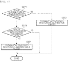
- FIG. 5 is a detailed flowchart in S270 step illustrated in FIG. 2 .
- a concentrated water flow rate adjustment valve may be opened by a predetermined opening angle according to an initial intake TDS value at the time of an initial operation (that is, when water is discharged) of a water purifier (S210).
- the opening degree of the concentrated water flow rate adjustment valve may be adjusted (S230).
- the opening degree of the concentrated water flow rate adjustment valve may be increased by a predetermined opening degree to increase the ratio of the concentrated water (that is, the recovery rate is decreased) (S232), and when the intake TDS value is reduced, the opening degree of the concentrated water flow rate adjustment valve may be decreased by a predetermined opening degree to reduce the ratio of the concentrated water (for example, the recovery rate is increased) (S233).
- the flow rates of the concentrated water and purified water may be measured (S240), and when the variation amount of the ratio of the concentrated water and purified water flow rates is equal to or greater than the second reference value (S250), the opening degree of the concentrated water flow rate adjustment valve may be finely adjusted (S260) .
- the opening degree of the concentrated water flow rate adjustment valve may be increased by a small amount by a predetermined opening angle to increase the ratio of the concentrated water (that is, the recovery rate is decreased) (S262), and when the ratio of the purified water is decreased, the opening degree of the concentrated water flow rate adjustment valve may be decreased by a small amount by a predetermined opening angle to decrease the ratio of the concentrated water (that is, the recovery rate is increased) (S263).
- the concentrated water flow rate adjustment valve may be operated when water is not discharged over a predetermined time (S280).
- the flow rate control method of the water purifier described above with reference to FIGS. 2 to 5 may be performed by a processor, or the like, mounted on the water purifier.
Landscapes
- Chemical & Material Sciences (AREA)
- Chemical Kinetics & Catalysis (AREA)
- Engineering & Computer Science (AREA)
- Water Supply & Treatment (AREA)
- Life Sciences & Earth Sciences (AREA)
- Hydrology & Water Resources (AREA)
- Environmental & Geological Engineering (AREA)
- Organic Chemistry (AREA)
- Nanotechnology (AREA)
- Separation Using Semi-Permeable Membranes (AREA)
- Water Treatment By Sorption (AREA)
Abstract
Description
- The present disclosure relates to a water purifier and a flow rate control method therefor.
- A water purifier may use a reverse osmosis filter to remove harmful components such as impurities, or the like, contained in water.
- Such a reverse osmosis filter may remove very fine impurities such as impurities, environmental hormones, heavy metals, bacteria, and the like, contained in water, by using a microfilm, and discharge the harmful components externally through a concentrated water channel.
- In this case, a ratio of purified water to water supplied to the filter may be referred to as a recovery rate, and the recovery rate may be adjusted by controlling an amount of concentrated water discharged through the concentrated water channel.
- Since the recovery rate is related to an ion removal performance of the reverse osmosis filter, to control the flow rate of the concentrated water may be important such that the recovery rate may be maintained at an appropriate value.
- Thus, Patent Document 1 described in the following prior art document discloses a water purifier.
- (Patent Document 1) Korean Patent Publication No.
10-2014-0024754 - Accordingly, there is a need in the art for a method for controlling a flow rate of concentrated water so as to maintain a certain level of an ion removal performance in a water purifier using a reverse osmosis filter.
- According to an aspect of the present disclosure, a water purifier may include: a filter unit for generating purified water by filtering influent water; a TDS measurement unit provided on a front end of the filter unit to measure TDS of water flowing into the filter unit; a second flow rate measurement unit provided on a rear end of the filter unit to measure a flow rate of the purified water discharged from the filter unit; a concentrated water flow rate adjustment valve for adjusting a flow rate of concentrated water discharged from the filter unit; and a control unit for controlling an opening degree of the concentrated water adjustment valve on a basis of a measurement value received from at least one of the TDS measurement unit, the first flow rate measurement unit, and the second flow rate measurement unit.
- According to another aspect of the present disclosure, a flow rate control method of a water purifier may include steps of: opening a concentrated water flow rate adjustment valve by a predetermined opening angle according to an initial intake TDS value measured at an initial operation of a water purifier; adjusting an opening degree of the concentrated water flow rate adjustment valve, when a variation amount of the intake TDS value is equal to or greater than a first reference value; and adjusting the opening degree of the concentrated water flow rate adjustment valve, when a variation amount of a ratio of concentrated water and purified water flow rates is equal to or greater than a second reference value.
- In addition, the means for solving the above-mentioned problems are not all enumerating the features of the present disclosure. The various features of the present disclosure and the advantages and effects thereof will be more fully understood by reference to the following specific embodiments.
- According to an embodiment of the present disclosure, an opening degree of a concentrated water flow rate adjustment valve may be precisely controlled on the basis of the intake TDS value and the flow rate of the concentrated water and the purified water.
-
-
FIG. 1 is a schematic view of a configuration of a water purifier according to an embodiment of the present disclosure. -
FIG. 2 is a flowchart of a flow rate control method of a water purifier according to another embodiment of the present disclosure. -
FIG. 3 is a detailed flowchart in step S230 illustrated inFIG. 2 . -
FIG. 4 is a detailed flowchart in step S260 illustrated inFIG. 2 . -
FIG. 5 is a detailed flowchart in step S270 illustrated inFIG. 2 . - Hereinafter, exemplary embodiments of the present disclosure will be described in detail with reference to the accompanying drawings. The disclosure may, however, be exemplified in many different forms and should not be construed as being limited to the specific embodiments set forth herein, and those skilled in the art and understanding the present disclosure can easily accomplish retrogressive inventions or other embodiments included in the scope of the present disclosure by the addition, modification, and removal of components within the same scope, but those are construed as being included in the scope of the present disclosure. Like reference numerals will be used to designate like components having similar functions throughout the drawings within the scope of the present disclosure.
- Throughout the specification, a configuration is referred to as being 'connected' to another configuration, including not only when the configurations are directly connected but also when they are indirectly connected with each other. In addition, when a component is referred to as "comprise" or "comprising," it means that it may include other components as well, rather than excluding other components, unless specifically stated otherwise.
-
FIG. 1 is a schematic view of a configuration of a water purifier according to an embodiment of the present disclosure. - Referring to
FIG. 1 , a water purifier according to an embodiment of the present disclosure may be configured to include: afilter unit 110, aTDS measurement unit 120, a first flowrate measurement unit 130, a second flowrate measurement unit 140, a concentrated water flowrate adjustment valve 150, and acontrol unit 160. - The
filter unit 110 may be for generating purified water by filtering influent water, and may be implemented with a reverse osmosis membrane filter. - The
filter unit 110 may be connected to a first flow path 1 through which water flows into thefilter unit 110, asecond flow path 2 through which purified water generated in thefilter unit 110 is discharged, and a third flow path 3 through which concentrated water filtered by thefilter unit 110 is discharged. Here, the concentrated water may refer to water containing solid substance filtered by thefilter unit 110, and may be discharged to externally through the third flow path 3. - Here, the water flowing into the
filter unit 110 may be raw water flowing from an outside, or may be water, for example, which has passed through a pre-treatment filter (not shown)including at least one of a sediment filter and a pre-carbon filter. - In addition, a post-treatment filter (not shown) including, for example, a post-carbon filter may be disposed on a rear end of the
filter unit 110, that is, on thesecond flow path 2. - The
TDS measurement unit 120 may be provided on the front end of thefilter unit 110, that is, on the first flow path 1 to measure the TDS of the water flowing into thefilter unit 110 through the first flow path 1. TheTDS measurement unit 120 may measure TDS of influent water, when water is flowing through the first flow path 1, and may transmit the measured TDS value to thecontrol unit 160. - The first flow
rate measurement unit 130 may be provided on the front end of thefilter unit 110, that is, on the first flow path 1, to measure the flow rate of the water (that is, raw water) flowing into thefilter unit 110 through the first flow path 1. The first flowrate measurement unit 130 may measure the flow rate of the influent water, when water is flowing through the first flow path 1, and may transmit the measured flow rate value to thecontrol unit 160. - The second flow
rate measurement unit 140 may be provided on the rear end of thefilter unit 110, that is, on thesecond flow path 2, to measure the flow rate of purified water discharged through thesecond flow path 2. The second flowrate measurement unit 140 may measure the flow rate of the discharged purified water when purified water is discharged through thesecond flow path 2, and may transmit the measured flow rate value to thecontrol unit 160. - The concentrated water flow
rate adjustment valve 150 may be provided on the third flow path 3, and may adjust the flow rate the concentrated water discharged through the third flow path 3 by opening and closing under a control of thecontrol unit 160. - According to an embodiment of the present disclosure, the concentrated water flow
rate adjustment valve 150 may be implemented to include a valve (not shown) capable of adjusting the flow rate of the concentrated water discharged through the third flow path 3 by adjusting a degree of opening and closing and a motor (not shown) for adjusting a degree of opening and closing of the valve according to a control signal transmitted from thecontrol unit 160. - The
control unit 160 may be for controlling an overall operation of awater purifier 100, and may be implemented, for example, to include at least one processing unit and a memory. Here, the processing unit may include, for example, a central processing unit (CPU), a graphics processing unit (GPU), a microprocessor, an application specific integrated circuit (ASIC), field programmable gate arrays (FPGA), and the like, and may have a plurality of cores. The memory may be a volatile memory, a non-volatile memory, or a combination thereof. - The
control unit 160 may control an opening degree of the concentrated water flowrate adjustment valve 150 on the basis of a measurement value received from at least one of theTDS measurement unit 120, the first flowrate measurement unit 130, and the second flowrate measurement unit 140. - Specifically, the
control unit 160 may open the concentrated water flowrate adjustment valve 150 by a predetermined opening angle according to the initial intake TDS value transmitted from theTDS measurement unit 120. Here, the predetermined opening angle may be derived by an experiment on a correlation between the initial intake TDS value and the recovery rate according to the opening angle of the concentrated water flowrate adjustment valve 150, and may be set at an optimum opening angle for accomplishing a target recovery rate according to the initial intake TDS value. - In addition, the
control unit 160 may adjust the opening degree of the concentrated water flowrate adjustment valve 150 when the variation amount of the intake TDS value transmitted from theTDS measurement unit 120 after opening the concentrated water flowrate adjustment valve 150 by the predetermined opening degree according to the initial intake TDS value. Specifically, thecontrol unit 160 may compare the initial intake TDS value transmitted from theTDS measurement unit 120 with the previously measured intake TDS value (for example, the initial intake TDS value), and when the intake TDS value is increased by a first reference value or more, the opening degree of the concentrated water flowrate adjustment valve 150 may be increased by the predetermined opening angle to increase a ratio of concentrated water (that is, the recovery rate is decreased), and when the intake TDS value is decreased by a first reference or more, the opening degree of the concentrated water flowrate adjustment valve 150 may be decreased by the predetermined opening angle to decrease a ratio of the concentrated water (that is, the recovery rate is increased) . - In addition, the
control unit 160 may grasp flow rates of concentrated water and purified water from the flow rate of raw water and the flow rate of purified water, transmitted from first and second flowrate measurement units rate adjustment valve 150 may be finely adjusted. Specifically, thecontrol unit 160 may compare the ratio of concentrated water and purified water flow rates with the previously calculated ratio of the concentrated water and the purified water flow rates (for example, the ratio of the concentrated water and purified water flow rates in the case of opening the concentrated water flowrate adjustment valve 150 by the predetermined opening angle according to the initial intake TDS value), and when the ratio of the purified water is increased by the second reference value or more, the opening degree of the concentrated water flowrate adjustment valve 150 may be increased by a small amount by a predetermined opening angle to increase the ratio of the concentrated water (that is, the recovery rate is decreased), and when the ratio of the purified water is decreased by the second reference value or more, the opening degree of the concentrated water flowrate adjustment valve 150 may be decreased by a small amount by a predetermined opening angle to decrease the ratio of the concentrated water (that is, the recovery rate is increased) . - In addition, the
control unit 160 may determine whether the concentrated water flowrate adjustment valve 150 is broken or clogged according to the variation amount of the ratio of the concentrated water and purified water flow rates after finely adjusting the opening degree of the concentrated water flowrate adjustment valve 150. Specifically, thecontrol unit 160 may determine that the concentrated water flowrate adjustment valve 150 is broken when there is no change in the ratio of the concentrated water and purified water flow rates even after finely adjusting the opening degree of the concentrated water flowrate adjustment valve 150, and when the variation amount of the concentrated water flow rate after finely adjusting the concentrated water flowrate adjustment valve 150 is equal to or lower than a third reference value, it can be determined that the concentrated water flowrate adjustment valve 150 is clogged. In this case, thecontrol unit 160 may inform an user of breakdown or clogging of the concentrated water flowrate adjustment valve 150 through a visual or audible notification means (not shown), or the like. - In addition, the
control unit 160 may operate the concentrated water flowrate adjustment valve 150 even when water is not discharged over a predetermined time (for example, may open, close, or return to an original opening degree after adjusting an opening degree of the concentrated water flow rate adjustment valve 150) . Accordingly, sticking or scale clogging or the valve, which may occur when the concentrated water flowrate adjustment valve 150 is not used for a long period of time may be prevented. - Hereinafter, a flow rate control method by the water purifier described above with reference to
FIGS. 2 to 5 will be described in detail. -
FIG. 2 is a flowchart of a flow rate control method of a water purifier according to another embodiment of the present disclosure,FIG. 3 is a detailed flowchart in S230 step,FIG. 4 is a detailed flowchart in S260 step illustrated inFIG. 2 , andFIG. 5 is a detailed flowchart in S270 step illustrated inFIG. 2 . - Referring to
FIG. 2 , a concentrated water flow rate adjustment valve may be opened by a predetermined opening angle according to an initial intake TDS value at the time of an initial operation (that is, when water is discharged) of a water purifier (S210). - Thereafter, when the variation amount of the intake TDS value is equal or greater than the first reference value (S220), the opening degree of the concentrated water flow rate adjustment valve may be adjusted (S230).
- Specifically, as illustrated in
FIG. 3 , when the intake TDS value is increased (S231), the opening degree of the concentrated water flow rate adjustment valve may be increased by a predetermined opening degree to increase the ratio of the concentrated water (that is, the recovery rate is decreased) (S232), and when the intake TDS value is reduced, the opening degree of the concentrated water flow rate adjustment valve may be decreased by a predetermined opening degree to reduce the ratio of the concentrated water (for example, the recovery rate is increased) (S233). - Thereafter, the flow rates of the concentrated water and purified water may be measured (S240), and when the variation amount of the ratio of the concentrated water and purified water flow rates is equal to or greater than the second reference value (S250), the opening degree of the concentrated water flow rate adjustment valve may be finely adjusted (S260) .
- Specifically, as illustrated in
FIG. 4 , when the ratio of the purified water is increased (S261), the opening degree of the concentrated water flow rate adjustment valve may be increased by a small amount by a predetermined opening angle to increase the ratio of the concentrated water (that is, the recovery rate is decreased) (S262), and when the ratio of the purified water is decreased, the opening degree of the concentrated water flow rate adjustment valve may be decreased by a small amount by a predetermined opening angle to decrease the ratio of the concentrated water (that is, the recovery rate is increased) (S263). - Thereafter, it is possible to determine whether the concentrated water flow rate adjustment valve is broken or clogged according to the variation amount of the ratio of the concentrated water and the purified water flow rates(S270).
- Specifically, as illustrated in
FIG. 5 , when there is no change in the ratio of the concentrated water and purified water flow rates even after finely adjusting the opening degree of the concentrated water flow rate adjustment valve (S271), it can be determined that the concentrated water flow rate adjustment valve is broken (S272) . On the other hand, when there is a change in the ratio of the concentrated water and purified water flow rates, but the variation amount of the concentrated water flow rate is equal to or lower than the third reference value (S273) , it can be determined that the concentrated water flow rate adjustment valve is clogged(S274). - Thereafter, the concentrated water flow rate adjustment valve may be operated when water is not discharged over a predetermined time (S280).
- The flow rate control method of the water purifier described above with reference to
FIGS. 2 to 5 may be performed by a processor, or the like, mounted on the water purifier. - While the present invention has been described with reference to exemplary embodiments in the present disclosure is not limited thereto, but various modifications may be made within the technical ideas of the present disclosure.
Claims (18)
- A water purifier comprising:a filter unit for generating purified water by filtering influent water;a TDS measurement unit provided on a front end of the filter unit to measure TDS of water flowing into the filter unit;a first flow rate measurement unit provided on the front end of the filter unit to measure a flow rate of the water flowing into the filter unit;a second flow rate measurement unit provided on a rear end of the filter unit to measure a flow rate of the purified water discharged from the filter unit;a concentrated water flow rate adjustment valve for adjusting a flow rate of concentrated water discharged from the filter unit; anda control unit for controlling an opening degree of the concentrated water flow rate adjustment valve on a basis of a measurement value received from at least one of the TDS measurement unit, the first flow rate measurement unit, and the second flow rate measurement unit.
- The water purifier of claim 1, wherein the control unit opens the concentrated water flow rate adjustment valve by a predetermined opening angle according to an initial TDS value transmitted from the TDS measurement unit.
- The water purifier of claim 1, wherein the control unit adjusts the opening degree of the concentrated water flow rate adjustment valve when a variation amount of the TDS value transmitted from the TDS measurement unit is equal to or greater than a first reference value.
- The water purifier of claim 3, wherein the control unit increases the opening degree of the concentrated water flow rate adjustment valve by a predetermined opening angle when the TDS value is increased.
- The water purifier of claim 3, wherein the control unit decreases the opening degree of the concentrated water flow rate adjustment valve by the predetermined opening angle when the TDS value is decreased.
- The water purifier of claim 1, wherein the control unit grasps flow rates of concentrated water and purified water transmitted from the first flow rate measurement unit and the second flow rate measurement unit, respectively, and adjusts the opening degree of the concentrated water flow rate adjustment valve when a variation amount of a ratio of the concentrated water and purified water flow rates is equal to or greater than a second reference value.
- The water purifier of claim 6, wherein the control unit increases the opening degree of the concentrated water flow rate adjustment valve by the predetermined opening angle when the ratio of purified water is increased.
- The water purifier of claim 6, wherein the control unit decreases the opening degree of the concentrated water flow rate adjustment valve by the predetermined opening angle when the ratio of purified water is decreased.
- The water purifier of claim 6, wherein the control unit determines whether the concentrated water flow rate adjustment valve is broken or clogged according to the variation amount of the ratio of the concentrated water and purified water flow rates.
- The water purifier of claim 9, wherein the control unit determines that the concentrated water flow rate adjustment valve is broken when there is no change in the ratio of the concentrated water and purified water flow rates even after adjusting the opening degree of the concentrated water flow rate adjustment valve.
- The water purifier of claim 9, wherein the control unit determines that the concentrated water flow rate adjustment valve is clogged when the variation amount of the concentrated water flow rate is equal to or lower than a third reference value.
- The water purifier of claim 1, wherein the control unit operates the concentrated water flow rate adjustment valve when water is not discharged over a predetermined time.
- A flow rate control method of a water purifier comprising steps of:opening a concentrated water flow rate adjustment valve by a predetermined opening angle according to an initial intake TDS value measured at an initial operation of a water purifier;adjusting an opening degree of the concentrated water flow rate adjustment valve when a variation amount of the intake TDS value is equal to or greater than a first reference value; andfinely adjusting the opening degree of the concentrated water flow rate adjustment valve when a variation amount of a ratio of the concentrated water and purified water flow rates is equal to or greater than a second reference value.
- The flow rate control method of the water purifier of claim 13, wherein the step of adjusting the opening degree of the concentrated water flow rate adjustment valve comprises steps of: increasing the concentrated water flow rate adjustment valve by the predetermined opening degree when the intake TDS value is increased; and
decreasing the concentrated water flow rate adjustment valve by the predetermined opening degree when the intake TDS value is decreased. - The flow rate control method of the water purifier of claim 13, wherein the step of finely adjusting the opening degree of the concentrated water flow rate adjustment valve comprises steps: increasing the opening degree of the concentrated water flow rate adjustment valve by the predetermined opening angle when the ratio of the purified water is increased; and
decreasing the opening degree of the concentrated water flow rate adjustment valve by the predetermined opening angle when the ratio of the purified water is decreased. - The flow rate control method of the water purifier of claim 13, further comprising a step of determining whether the concentrated water flow rate adjustment valve is broken or clogged according to the variation amount the ratio of the concentrated water and the purified water flow rates.
- The flow rate control method of the water purifier of claim 16, wherein the step of determining whether the concentrated water flow rate adjustment valve is broken or clogged comprises steps: determining that the concentrated water flow rate adjustment valve is broken when there is no change in the ratio of the concentrated water and the purified water flow rates even after finely adjusting the opening degree of the concentrated water flow rate adjustment valve; or
determining that the concentrated water flow rate adjustment valve is clogged when there is a change in the ratio of the concentrated water and the purified water flow rates, but the variation amount of the concentrated water flow rate is equal to or lower than a third reference value. - The flow rate control method of the water purifier of claim 13, further comprising a step of operating the concentrated water flow rate adjustment valve when water is not discharged over the predetermined time.
Applications Claiming Priority (2)
| Application Number | Priority Date | Filing Date | Title |
|---|---|---|---|
| KR1020160168597A KR101936747B1 (en) | 2016-12-12 | 2016-12-12 | Water purifying apparatus and flow rate control method thereof |
| PCT/KR2017/013788 WO2018110868A1 (en) | 2016-12-12 | 2017-11-29 | Water purifier and flow rate control method therefor |
Publications (4)
| Publication Number | Publication Date |
|---|---|
| EP3552682A1 true EP3552682A1 (en) | 2019-10-16 |
| EP3552682A4 EP3552682A4 (en) | 2020-01-22 |
| EP3552682B1 EP3552682B1 (en) | 2024-07-10 |
| EP3552682C0 EP3552682C0 (en) | 2024-07-10 |
Family
ID=62558869
Family Applications (1)
| Application Number | Title | Priority Date | Filing Date |
|---|---|---|---|
| EP17881972.8A Active EP3552682B1 (en) | 2016-12-12 | 2017-11-29 | Water purifier |
Country Status (5)
| Country | Link |
|---|---|
| US (2) | US11285415B2 (en) |
| EP (1) | EP3552682B1 (en) |
| KR (1) | KR101936747B1 (en) |
| CN (1) | CN110062648A (en) |
| WO (1) | WO2018110868A1 (en) |
Families Citing this family (6)
| Publication number | Priority date | Publication date | Assignee | Title |
|---|---|---|---|---|
| KR20170125561A (en) * | 2016-05-04 | 2017-11-15 | 엘지전자 주식회사 | Apparatus for controlling water purifier, water purifier and method for controlling thereof |
| KR102674377B1 (en) * | 2018-12-31 | 2024-06-12 | 코웨이 주식회사 | Water purifier and controling method thereof |
| CN111003765A (en) * | 2019-12-31 | 2020-04-14 | 佛山市云米电器科技有限公司 | Water purification system and water purifier with constant proportion of pure wastewater |
| CN113979494A (en) * | 2021-12-08 | 2022-01-28 | 珠海格力电器股份有限公司 | Water purifier and water purifier control method |
| CN116772413B (en) * | 2022-03-09 | 2026-01-13 | 艾欧史密斯(中国)热水器有限公司 | Fuel and soft integrated machine and control method thereof |
| CN116081774A (en) * | 2022-12-28 | 2023-05-09 | 珠海格力电器股份有限公司 | Water purifier and control method thereof |
Family Cites Families (18)
| Publication number | Priority date | Publication date | Assignee | Title |
|---|---|---|---|---|
| JP3311158B2 (en) * | 1994-08-01 | 2002-08-05 | 東芝アイティー・コントロールシステム株式会社 | Operation control device for desalination plant |
| JPH08229554A (en) * | 1995-02-28 | 1996-09-10 | Toshiba Corp | Operation controller for reverse osmosis water desalination plant |
| KR0175900B1 (en) * | 1996-03-27 | 1999-03-20 | 김광호 | Raw water supply status sensing device of water purifier |
| JP2003225662A (en) * | 2002-02-07 | 2003-08-12 | Hyi Dong Jung | Reverse osmosis water purifier capable of measuring water quality and flow rate |
| KR20090095052A (en) * | 2008-03-04 | 2009-09-09 | 정석동 | A water purifier and control method of the same |
| FR2933969B1 (en) * | 2008-07-21 | 2011-11-11 | Degremont | INSTALLATION OF WATER DESALINATION BY REVERSE OSMOSIS |
| KR100973912B1 (en) * | 2010-01-07 | 2010-08-03 | 박광천 | Economical reverse osmosis water purification system |
| JP5417301B2 (en) | 2010-11-10 | 2014-02-12 | パナソニック株式会社 | Water treatment equipment |
| JP5834687B2 (en) * | 2011-09-22 | 2015-12-24 | 三浦工業株式会社 | Water treatment system |
| WO2014014866A1 (en) * | 2012-07-18 | 2014-01-23 | Mag Aerospace Industries, Inc. | Systems and methods for treating grey water on-board passenger transport vehicles |
| WO2014018896A1 (en) | 2012-07-27 | 2014-01-30 | Deka Products Limited Partnership | Control of conductivity in product water outlet for evaporation apparatus |
| KR101409901B1 (en) | 2012-08-21 | 2014-07-02 | 엘지전자 주식회사 | A water purifier |
| CN103908894B (en) | 2013-01-08 | 2016-08-24 | 美的集团股份有限公司 | Water purifier and water production control method thereof |
| KR102046474B1 (en) * | 2013-03-06 | 2019-11-20 | 웅진코웨이 주식회사 | System of controlling amount of purified water for electro deionization type water purifier |
| CN104722207A (en) | 2013-12-24 | 2015-06-24 | 珠海格力电器股份有限公司 | Water purification system, control method thereof and water purifier |
| CN107108296A (en) * | 2014-11-11 | 2017-08-29 | 默克专利股份公司 | Water purification system and method |
| KR102301484B1 (en) * | 2014-12-29 | 2021-09-15 | 코웨이 주식회사 | Deionization filter device and water treatment apparatus having the same |
| CN105771657B (en) | 2016-05-09 | 2019-03-08 | 佛山市云米电器科技有限公司 | A kind of water flow adjusting method of water purification system and its condensed water and pure water |
-
2016
- 2016-12-12 KR KR1020160168597A patent/KR101936747B1/en active Active
-
2017
- 2017-11-29 US US16/468,529 patent/US11285415B2/en active Active
- 2017-11-29 EP EP17881972.8A patent/EP3552682B1/en active Active
- 2017-11-29 WO PCT/KR2017/013788 patent/WO2018110868A1/en not_active Ceased
- 2017-11-29 CN CN201780076511.3A patent/CN110062648A/en active Pending
-
2022
- 2022-03-02 US US17/684,866 patent/US11534709B2/en active Active
Also Published As
| Publication number | Publication date |
|---|---|
| CN110062648A (en) | 2019-07-26 |
| KR20180067150A (en) | 2018-06-20 |
| EP3552682B1 (en) | 2024-07-10 |
| EP3552682C0 (en) | 2024-07-10 |
| US11285415B2 (en) | 2022-03-29 |
| EP3552682A4 (en) | 2020-01-22 |
| US11534709B2 (en) | 2022-12-27 |
| US20220184537A1 (en) | 2022-06-16 |
| US20190329168A1 (en) | 2019-10-31 |
| WO2018110868A1 (en) | 2018-06-21 |
| KR101936747B1 (en) | 2019-01-11 |
Similar Documents
| Publication | Publication Date | Title |
|---|---|---|
| EP3552682B1 (en) | Water purifier | |
| US12053742B2 (en) | Water conditioning systems having diversion devices | |
| KR102490252B1 (en) | Water purifying apparatus and recovery rate control method thereof | |
| CN116040703B (en) | Water purifier and water purifier control method | |
| EP3485954B1 (en) | Water purifier | |
| AU2014235024B2 (en) | Process for water treatment prior to reverse osmosis | |
| JP5691709B2 (en) | Water purification method and water purification device | |
| EP4321488A1 (en) | Electrodeionization system and control method for electrodeionization system | |
| JP5782631B2 (en) | Mixer tap | |
| CN211896191U (en) | Water purification system and water purifier with constant proportion of pure wastewater | |
| KR20170127176A (en) | Water purifying apparatus | |
| KR102490255B1 (en) | Apparatus for controlling total disolved solids and water treatment apparatus having the same | |
| CN214060016U (en) | Water purifier provided with deionizing filter | |
| KR102121801B1 (en) | Water purifier having deionization filter and control method thereof | |
| CN105329984A (en) | Water purifier and control method thereof | |
| KR101144580B1 (en) | Apparatus and method for membrane filtration with automatic coagulating control using screaming current | |
| CN104998545A (en) | Reverse osmosis membrane purifier and purifier | |
| JPH10202242A (en) | Adjusting the resistivity of ultrapure water | |
| JP4403849B2 (en) | Aggregation processing method and apparatus | |
| JP2014034005A (en) | Salt water desalination apparatus and fresh water production method | |
| JP6743409B2 (en) | Method of controlling pH in neutralization tank | |
| CN121100016A (en) | Device and method for reducing waste water in laboratory water purification system | |
| CN111003765A (en) | Water purification system and water purifier with constant proportion of pure wastewater | |
| JP2002336871A (en) | Method for controlling injection of flocculant in membrane filtration | |
| CN103713664B (en) | Sewage treatment control method, device, system and sewage treatment facility |
Legal Events
| Date | Code | Title | Description |
|---|---|---|---|
| STAA | Information on the status of an ep patent application or granted ep patent |
Free format text: STATUS: THE INTERNATIONAL PUBLICATION HAS BEEN MADE |
|
| PUAI | Public reference made under article 153(3) epc to a published international application that has entered the european phase |
Free format text: ORIGINAL CODE: 0009012 |
|
| STAA | Information on the status of an ep patent application or granted ep patent |
Free format text: STATUS: REQUEST FOR EXAMINATION WAS MADE |
|
| 17P | Request for examination filed |
Effective date: 20190624 |
|
| AK | Designated contracting states |
Kind code of ref document: A1 Designated state(s): AL AT BE BG CH CY CZ DE DK EE ES FI FR GB GR HR HU IE IS IT LI LT LU LV MC MK MT NL NO PL PT RO RS SE SI SK SM TR |
|
| AX | Request for extension of the european patent |
Extension state: BA ME |
|
| A4 | Supplementary search report drawn up and despatched |
Effective date: 20200107 |
|
| RIC1 | Information provided on ipc code assigned before grant |
Ipc: B01D 61/02 20060101ALI20191219BHEP Ipc: B01D 37/04 20060101AFI20191219BHEP Ipc: C02F 1/44 20060101ALI20191219BHEP Ipc: C02F 1/00 20060101ALI20191219BHEP Ipc: B01D 35/157 20060101ALI20191219BHEP |
|
| DAV | Request for validation of the european patent (deleted) | ||
| DAX | Request for extension of the european patent (deleted) | ||
| STAA | Information on the status of an ep patent application or granted ep patent |
Free format text: STATUS: EXAMINATION IS IN PROGRESS |
|
| 17Q | First examination report despatched |
Effective date: 20220531 |
|
| GRAP | Despatch of communication of intention to grant a patent |
Free format text: ORIGINAL CODE: EPIDOSNIGR1 |
|
| STAA | Information on the status of an ep patent application or granted ep patent |
Free format text: STATUS: GRANT OF PATENT IS INTENDED |
|
| INTG | Intention to grant announced |
Effective date: 20240131 |
|
| GRAS | Grant fee paid |
Free format text: ORIGINAL CODE: EPIDOSNIGR3 |
|
| GRAA | (expected) grant |
Free format text: ORIGINAL CODE: 0009210 |
|
| STAA | Information on the status of an ep patent application or granted ep patent |
Free format text: STATUS: THE PATENT HAS BEEN GRANTED |
|
| AK | Designated contracting states |
Kind code of ref document: B1 Designated state(s): AL AT BE BG CH CY CZ DE DK EE ES FI FR GB GR HR HU IE IS IT LI LT LU LV MC MK MT NL NO PL PT RO RS SE SI SK SM TR |
|
| REG | Reference to a national code |
Ref country code: CH Ref legal event code: EP |
|
| REG | Reference to a national code |
Ref country code: DE Ref legal event code: R096 Ref document number: 602017083270 Country of ref document: DE |
|
| U01 | Request for unitary effect filed |
Effective date: 20240712 |
|
| U07 | Unitary effect registered |
Designated state(s): AT BE BG DE DK EE FI FR IT LT LU LV MT NL PT SE SI Effective date: 20240726 |
|
| U20 | Renewal fee for the european patent with unitary effect paid |
Year of fee payment: 8 Effective date: 20241122 |
|
| PG25 | Lapsed in a contracting state [announced via postgrant information from national office to epo] |
Ref country code: NO Free format text: LAPSE BECAUSE OF FAILURE TO SUBMIT A TRANSLATION OF THE DESCRIPTION OR TO PAY THE FEE WITHIN THE PRESCRIBED TIME-LIMIT Effective date: 20241010 |
|
| PG25 | Lapsed in a contracting state [announced via postgrant information from national office to epo] |
Ref country code: GR Free format text: LAPSE BECAUSE OF FAILURE TO SUBMIT A TRANSLATION OF THE DESCRIPTION OR TO PAY THE FEE WITHIN THE PRESCRIBED TIME-LIMIT Effective date: 20241011 Ref country code: PL Free format text: LAPSE BECAUSE OF FAILURE TO SUBMIT A TRANSLATION OF THE DESCRIPTION OR TO PAY THE FEE WITHIN THE PRESCRIBED TIME-LIMIT Effective date: 20240710 |
|
| PG25 | Lapsed in a contracting state [announced via postgrant information from national office to epo] |
Ref country code: IS Free format text: LAPSE BECAUSE OF FAILURE TO SUBMIT A TRANSLATION OF THE DESCRIPTION OR TO PAY THE FEE WITHIN THE PRESCRIBED TIME-LIMIT Effective date: 20241110 |
|
| PG25 | Lapsed in a contracting state [announced via postgrant information from national office to epo] |
Ref country code: HR Free format text: LAPSE BECAUSE OF FAILURE TO SUBMIT A TRANSLATION OF THE DESCRIPTION OR TO PAY THE FEE WITHIN THE PRESCRIBED TIME-LIMIT Effective date: 20240710 |
|
| PG25 | Lapsed in a contracting state [announced via postgrant information from national office to epo] |
Ref country code: ES Free format text: LAPSE BECAUSE OF FAILURE TO SUBMIT A TRANSLATION OF THE DESCRIPTION OR TO PAY THE FEE WITHIN THE PRESCRIBED TIME-LIMIT Effective date: 20240710 Ref country code: RS Free format text: LAPSE BECAUSE OF FAILURE TO SUBMIT A TRANSLATION OF THE DESCRIPTION OR TO PAY THE FEE WITHIN THE PRESCRIBED TIME-LIMIT Effective date: 20241010 |
|
| PG25 | Lapsed in a contracting state [announced via postgrant information from national office to epo] |
Ref country code: RS Free format text: LAPSE BECAUSE OF FAILURE TO SUBMIT A TRANSLATION OF THE DESCRIPTION OR TO PAY THE FEE WITHIN THE PRESCRIBED TIME-LIMIT Effective date: 20241010 Ref country code: PL Free format text: LAPSE BECAUSE OF FAILURE TO SUBMIT A TRANSLATION OF THE DESCRIPTION OR TO PAY THE FEE WITHIN THE PRESCRIBED TIME-LIMIT Effective date: 20240710 Ref country code: NO Free format text: LAPSE BECAUSE OF FAILURE TO SUBMIT A TRANSLATION OF THE DESCRIPTION OR TO PAY THE FEE WITHIN THE PRESCRIBED TIME-LIMIT Effective date: 20241010 Ref country code: IS Free format text: LAPSE BECAUSE OF FAILURE TO SUBMIT A TRANSLATION OF THE DESCRIPTION OR TO PAY THE FEE WITHIN THE PRESCRIBED TIME-LIMIT Effective date: 20241110 Ref country code: HR Free format text: LAPSE BECAUSE OF FAILURE TO SUBMIT A TRANSLATION OF THE DESCRIPTION OR TO PAY THE FEE WITHIN THE PRESCRIBED TIME-LIMIT Effective date: 20240710 Ref country code: GR Free format text: LAPSE BECAUSE OF FAILURE TO SUBMIT A TRANSLATION OF THE DESCRIPTION OR TO PAY THE FEE WITHIN THE PRESCRIBED TIME-LIMIT Effective date: 20241011 Ref country code: ES Free format text: LAPSE BECAUSE OF FAILURE TO SUBMIT A TRANSLATION OF THE DESCRIPTION OR TO PAY THE FEE WITHIN THE PRESCRIBED TIME-LIMIT Effective date: 20240710 |
|
| PG25 | Lapsed in a contracting state [announced via postgrant information from national office to epo] |
Ref country code: SM Free format text: LAPSE BECAUSE OF FAILURE TO SUBMIT A TRANSLATION OF THE DESCRIPTION OR TO PAY THE FEE WITHIN THE PRESCRIBED TIME-LIMIT Effective date: 20240710 |
|
| PG25 | Lapsed in a contracting state [announced via postgrant information from national office to epo] |
Ref country code: CZ Free format text: LAPSE BECAUSE OF FAILURE TO SUBMIT A TRANSLATION OF THE DESCRIPTION OR TO PAY THE FEE WITHIN THE PRESCRIBED TIME-LIMIT Effective date: 20240710 |
|
| PG25 | Lapsed in a contracting state [announced via postgrant information from national office to epo] |
Ref country code: SK Free format text: LAPSE BECAUSE OF FAILURE TO SUBMIT A TRANSLATION OF THE DESCRIPTION OR TO PAY THE FEE WITHIN THE PRESCRIBED TIME-LIMIT Effective date: 20240710 |
|
| PLBE | No opposition filed within time limit |
Free format text: ORIGINAL CODE: 0009261 |
|
| STAA | Information on the status of an ep patent application or granted ep patent |
Free format text: STATUS: NO OPPOSITION FILED WITHIN TIME LIMIT |
|
| 26N | No opposition filed |
Effective date: 20250411 |
|
| REG | Reference to a national code |
Ref country code: CH Ref legal event code: PL |
|
| PG25 | Lapsed in a contracting state [announced via postgrant information from national office to epo] |
Ref country code: MC Free format text: LAPSE BECAUSE OF FAILURE TO SUBMIT A TRANSLATION OF THE DESCRIPTION OR TO PAY THE FEE WITHIN THE PRESCRIBED TIME-LIMIT Effective date: 20240710 |
|
| REG | Reference to a national code |
Ref country code: CH Ref legal event code: PL |
|
| GBPC | Gb: european patent ceased through non-payment of renewal fee |
Effective date: 20241129 |
|
| PG25 | Lapsed in a contracting state [announced via postgrant information from national office to epo] |
Ref country code: CH Free format text: LAPSE BECAUSE OF NON-PAYMENT OF DUE FEES Effective date: 20241130 |
|
| PG25 | Lapsed in a contracting state [announced via postgrant information from national office to epo] |
Ref country code: GB Free format text: LAPSE BECAUSE OF NON-PAYMENT OF DUE FEES Effective date: 20241129 |
|
| PG25 | Lapsed in a contracting state [announced via postgrant information from national office to epo] |
Ref country code: IE Free format text: LAPSE BECAUSE OF NON-PAYMENT OF DUE FEES Effective date: 20241129 |
|
| PG25 | Lapsed in a contracting state [announced via postgrant information from national office to epo] |
Ref country code: RO Free format text: LAPSE BECAUSE OF FAILURE TO SUBMIT A TRANSLATION OF THE DESCRIPTION OR TO PAY THE FEE WITHIN THE PRESCRIBED TIME-LIMIT Effective date: 20240710 |
|
| U20 | Renewal fee for the european patent with unitary effect paid |
Year of fee payment: 9 Effective date: 20251124 |
|
| PG25 | Lapsed in a contracting state [announced via postgrant information from national office to epo] |
Ref country code: HU Free format text: LAPSE BECAUSE OF FAILURE TO SUBMIT A TRANSLATION OF THE DESCRIPTION OR TO PAY THE FEE WITHIN THE PRESCRIBED TIME-LIMIT; INVALID AB INITIO Effective date: 20171129 |
|
| PG25 | Lapsed in a contracting state [announced via postgrant information from national office to epo] |
Ref country code: CY Free format text: LAPSE BECAUSE OF FAILURE TO SUBMIT A TRANSLATION OF THE DESCRIPTION OR TO PAY THE FEE WITHIN THE PRESCRIBED TIME-LIMIT; INVALID AB INITIO Effective date: 20171129 |