EP3552585B1 - Système de délivrance de valvule cardiaque prothétique à transcathéter à charnière - Google Patents
Système de délivrance de valvule cardiaque prothétique à transcathéter à charnière Download PDFInfo
- Publication number
- EP3552585B1 EP3552585B1 EP19178780.3A EP19178780A EP3552585B1 EP 3552585 B1 EP3552585 B1 EP 3552585B1 EP 19178780 A EP19178780 A EP 19178780A EP 3552585 B1 EP3552585 B1 EP 3552585B1
- Authority
- EP
- European Patent Office
- Prior art keywords
- hinge
- hub
- delivery device
- segments
- heart valve
- Prior art date
- Legal status (The legal status is an assumption and is not a legal conclusion. Google has not performed a legal analysis and makes no representation as to the accuracy of the status listed.)
- Active
Links
Images


Classifications
-
- A—HUMAN NECESSITIES
- A61—MEDICAL OR VETERINARY SCIENCE; HYGIENE
- A61F—FILTERS IMPLANTABLE INTO BLOOD VESSELS; PROSTHESES; DEVICES PROVIDING PATENCY TO, OR PREVENTING COLLAPSING OF, TUBULAR STRUCTURES OF THE BODY, e.g. STENTS; ORTHOPAEDIC, NURSING OR CONTRACEPTIVE DEVICES; FOMENTATION; TREATMENT OR PROTECTION OF EYES OR EARS; BANDAGES, DRESSINGS OR ABSORBENT PADS; FIRST-AID KITS
- A61F2/00—Filters implantable into blood vessels; Prostheses, i.e. artificial substitutes or replacements for parts of the body; Appliances for connecting them with the body; Devices providing patency to, or preventing collapsing of, tubular structures of the body, e.g. stents
- A61F2/02—Prostheses implantable into the body
- A61F2/24—Heart valves ; Vascular valves, e.g. venous valves; Heart implants, e.g. passive devices for improving the function of the native valve or the heart muscle; Transmyocardial revascularisation [TMR] devices; Valves implantable in the body
- A61F2/2427—Devices for manipulating or deploying heart valves during implantation
- A61F2/2436—Deployment by retracting a sheath
-
- A—HUMAN NECESSITIES
- A61—MEDICAL OR VETERINARY SCIENCE; HYGIENE
- A61F—FILTERS IMPLANTABLE INTO BLOOD VESSELS; PROSTHESES; DEVICES PROVIDING PATENCY TO, OR PREVENTING COLLAPSING OF, TUBULAR STRUCTURES OF THE BODY, e.g. STENTS; ORTHOPAEDIC, NURSING OR CONTRACEPTIVE DEVICES; FOMENTATION; TREATMENT OR PROTECTION OF EYES OR EARS; BANDAGES, DRESSINGS OR ABSORBENT PADS; FIRST-AID KITS
- A61F2/00—Filters implantable into blood vessels; Prostheses, i.e. artificial substitutes or replacements for parts of the body; Appliances for connecting them with the body; Devices providing patency to, or preventing collapsing of, tubular structures of the body, e.g. stents
- A61F2/02—Prostheses implantable into the body
- A61F2/24—Heart valves ; Vascular valves, e.g. venous valves; Heart implants, e.g. passive devices for improving the function of the native valve or the heart muscle; Transmyocardial revascularisation [TMR] devices; Valves implantable in the body
- A61F2/2409—Support rings therefor, e.g. for connecting valves to tissue
-
- A—HUMAN NECESSITIES
- A61—MEDICAL OR VETERINARY SCIENCE; HYGIENE
- A61F—FILTERS IMPLANTABLE INTO BLOOD VESSELS; PROSTHESES; DEVICES PROVIDING PATENCY TO, OR PREVENTING COLLAPSING OF, TUBULAR STRUCTURES OF THE BODY, e.g. STENTS; ORTHOPAEDIC, NURSING OR CONTRACEPTIVE DEVICES; FOMENTATION; TREATMENT OR PROTECTION OF EYES OR EARS; BANDAGES, DRESSINGS OR ABSORBENT PADS; FIRST-AID KITS
- A61F2/00—Filters implantable into blood vessels; Prostheses, i.e. artificial substitutes or replacements for parts of the body; Appliances for connecting them with the body; Devices providing patency to, or preventing collapsing of, tubular structures of the body, e.g. stents
- A61F2/02—Prostheses implantable into the body
- A61F2/24—Heart valves ; Vascular valves, e.g. venous valves; Heart implants, e.g. passive devices for improving the function of the native valve or the heart muscle; Transmyocardial revascularisation [TMR] devices; Valves implantable in the body
- A61F2/2412—Heart valves ; Vascular valves, e.g. venous valves; Heart implants, e.g. passive devices for improving the function of the native valve or the heart muscle; Transmyocardial revascularisation [TMR] devices; Valves implantable in the body with soft flexible valve members, e.g. tissue valves shaped like natural valves
-
- A—HUMAN NECESSITIES
- A61—MEDICAL OR VETERINARY SCIENCE; HYGIENE
- A61F—FILTERS IMPLANTABLE INTO BLOOD VESSELS; PROSTHESES; DEVICES PROVIDING PATENCY TO, OR PREVENTING COLLAPSING OF, TUBULAR STRUCTURES OF THE BODY, e.g. STENTS; ORTHOPAEDIC, NURSING OR CONTRACEPTIVE DEVICES; FOMENTATION; TREATMENT OR PROTECTION OF EYES OR EARS; BANDAGES, DRESSINGS OR ABSORBENT PADS; FIRST-AID KITS
- A61F2/00—Filters implantable into blood vessels; Prostheses, i.e. artificial substitutes or replacements for parts of the body; Appliances for connecting them with the body; Devices providing patency to, or preventing collapsing of, tubular structures of the body, e.g. stents
- A61F2/02—Prostheses implantable into the body
- A61F2/24—Heart valves ; Vascular valves, e.g. venous valves; Heart implants, e.g. passive devices for improving the function of the native valve or the heart muscle; Transmyocardial revascularisation [TMR] devices; Valves implantable in the body
- A61F2/2427—Devices for manipulating or deploying heart valves during implantation
- A61F2/243—Deployment by mechanical expansion
-
- A—HUMAN NECESSITIES
- A61—MEDICAL OR VETERINARY SCIENCE; HYGIENE
- A61F—FILTERS IMPLANTABLE INTO BLOOD VESSELS; PROSTHESES; DEVICES PROVIDING PATENCY TO, OR PREVENTING COLLAPSING OF, TUBULAR STRUCTURES OF THE BODY, e.g. STENTS; ORTHOPAEDIC, NURSING OR CONTRACEPTIVE DEVICES; FOMENTATION; TREATMENT OR PROTECTION OF EYES OR EARS; BANDAGES, DRESSINGS OR ABSORBENT PADS; FIRST-AID KITS
- A61F2/00—Filters implantable into blood vessels; Prostheses, i.e. artificial substitutes or replacements for parts of the body; Appliances for connecting them with the body; Devices providing patency to, or preventing collapsing of, tubular structures of the body, e.g. stents
- A61F2/02—Prostheses implantable into the body
- A61F2/24—Heart valves ; Vascular valves, e.g. venous valves; Heart implants, e.g. passive devices for improving the function of the native valve or the heart muscle; Transmyocardial revascularisation [TMR] devices; Valves implantable in the body
- A61F2/2442—Annuloplasty rings or inserts for correcting the valve shape; Implants for improving the function of a native heart valve
- A61F2/2466—Delivery devices therefor
-
- A—HUMAN NECESSITIES
- A61—MEDICAL OR VETERINARY SCIENCE; HYGIENE
- A61M—DEVICES FOR INTRODUCING MEDIA INTO, OR ONTO, THE BODY; DEVICES FOR TRANSDUCING BODY MEDIA OR FOR TAKING MEDIA FROM THE BODY; DEVICES FOR PRODUCING OR ENDING SLEEP OR STUPOR
- A61M25/00—Catheters; Hollow probes
- A61M25/01—Introducing, guiding, advancing, emplacing or holding catheters
- A61M25/0105—Steering means as part of the catheter or advancing means; Markers for positioning
- A61M25/0133—Tip steering devices
- A61M25/0138—Tip steering devices having flexible regions as a result of weakened outer material, e.g. slots, slits, cuts, joints or coils
-
- A—HUMAN NECESSITIES
- A61—MEDICAL OR VETERINARY SCIENCE; HYGIENE
- A61F—FILTERS IMPLANTABLE INTO BLOOD VESSELS; PROSTHESES; DEVICES PROVIDING PATENCY TO, OR PREVENTING COLLAPSING OF, TUBULAR STRUCTURES OF THE BODY, e.g. STENTS; ORTHOPAEDIC, NURSING OR CONTRACEPTIVE DEVICES; FOMENTATION; TREATMENT OR PROTECTION OF EYES OR EARS; BANDAGES, DRESSINGS OR ABSORBENT PADS; FIRST-AID KITS
- A61F2/00—Filters implantable into blood vessels; Prostheses, i.e. artificial substitutes or replacements for parts of the body; Appliances for connecting them with the body; Devices providing patency to, or preventing collapsing of, tubular structures of the body, e.g. stents
- A61F2/02—Prostheses implantable into the body
- A61F2/24—Heart valves ; Vascular valves, e.g. venous valves; Heart implants, e.g. passive devices for improving the function of the native valve or the heart muscle; Transmyocardial revascularisation [TMR] devices; Valves implantable in the body
- A61F2/2412—Heart valves ; Vascular valves, e.g. venous valves; Heart implants, e.g. passive devices for improving the function of the native valve or the heart muscle; Transmyocardial revascularisation [TMR] devices; Valves implantable in the body with soft flexible valve members, e.g. tissue valves shaped like natural valves
- A61F2/2418—Scaffolds therefor, e.g. support stents
-
- A—HUMAN NECESSITIES
- A61—MEDICAL OR VETERINARY SCIENCE; HYGIENE
- A61M—DEVICES FOR INTRODUCING MEDIA INTO, OR ONTO, THE BODY; DEVICES FOR TRANSDUCING BODY MEDIA OR FOR TAKING MEDIA FROM THE BODY; DEVICES FOR PRODUCING OR ENDING SLEEP OR STUPOR
- A61M25/00—Catheters; Hollow probes
- A61M25/01—Introducing, guiding, advancing, emplacing or holding catheters
- A61M25/0105—Steering means as part of the catheter or advancing means; Markers for positioning
- A61M25/0133—Tip steering devices
- A61M25/0147—Tip steering devices with movable mechanical means, e.g. pull wires
Definitions
- the present disclosure relates to delivery devices for implanting transcatheter valves. More particularly, it relates to catheter-based devices with controlled deflection for implanting a prosthetic heart valve.
- a human heart includes four heart valves that determine the pathway of blood flow through the heart: the mitral valve, the tricuspid valve, the aortic valve, and the pulmonary valve.
- the mitral and tricuspid valves are atrio-ventricular valves, which are between the atria and the ventricles, while the aortic and pulmonary valves are semilunar valves, which are in the arteries leaving the heart.
- native leaflets of a heart valve move apart from each other when the valve is in an open position, and meet or "coapt" when the valve is in a closed position.
- valves problems that may develop with valves include stenosis in which a valve does not open properly, and/or insufficiency or regurgitation in which a valve does not close properly. Stenosis and insufficiency may occur concomitantly in the same valve. The effects of valvular dysfunction vary, with regurgitation or backflow typically having relatively severe physiological consequences to the patient.
- Heart valves can be repaired or replaced using a variety of different types of heart valve surgeries.
- One conventional technique involves an open-heart surgical approach that is conducted under general anesthesia, during which the heart is stopped and blood flow is controlled by a heart-lung bypass machine.
- an expandable prosthetic valve is compressed about or within a catheter, inserted inside a body lumen of the patient, such as the femoral artery, and delivered to a desired location in the heart.
- the heart valve prosthesis employed with catheter-based, or transcatheter, procedures generally includes an expandable multi-level frame or stent that supports a valve structure having a plurality of leaflets.
- the frame can be contracted during percutaneous transluminal delivery, and expanded upon deployment at or within the native valve.
- One type of valve stent can be initially provided in an expanded or uncrimped condition, then crimped or compressed about a balloon portion of a catheter. The balloon is subsequently inflated to expand and deploy the prosthetic heart valve.
- the stent frame is formed to be self-expanding. With these systems, the valved stent is crimped down to a desired size and held in that compressed state within a sheath for transluminal delivery.
- any particular transcatheter prosthetic heart valve is dependent, at least to some extent, upon the valve being replaced or repaired (i.e., mitral valve, tricuspid valve, aortic valve, or pulmonary valve).
- the stent frame must oftentimes provide and maintain (e.g., elevated hoop strength and resistance to radially compressive forces) a relatively complex shape in order to achieve desired fixation with the corresponding native anatomy.
- these design features can give rise to delivery obstacles. For example, when compressed and constrained within the delivery device's outer sheath capsule, a self-expanding stent frame will exert significant radial forces on the capsule.
- the capsule must have a robust construction, capable of statically resisting the applied force.
- the preferred delivery approach oftentimes includes one or more significant bends or turns.
- the native anatomy creates the "tight" or small radius of curvature bends; as the capsule (or other components of the delivery device) comes into atraumatic contact with the native anatomy, the native anatomy naturally assists in "forcing" the outer sheath (including the capsule) to the necessary shape.
- a retrograde approach to the aortic valve is but one example, where contact with the native anatomy assists in directing the delivery device about the significant curvature of the aortic arch.
- the mitral valve is oftentimes approached at the left atrium via an opening in the atrial septum.
- the outer sheath must form a bend angle on the order of 45 degrees in order to position the capsule at the native mitral valve.
- a guide wire can be employed to direct or steer the delivery tool along the necessary path of curvature in achieving this desired orientation. Where the outer sheath has a bulked configuration, it can be difficult to effectuate the necessary bend with only the guide wire.
- distal and proximal are used in the following description with respect to a position or direction relative to the treating clinician.
- distal or disally are a position distant from or in a direction away from the clinician.
- Proximal and “proximally” are a position near or in a direction toward the clinician.
- outward or outwardly refer to a position radially away from a longitudinal axis of a frame of the valve prosthesis and the terms “inward” or “inwardly” refer to a position radially toward a longitudinal axis of the frame of the valve prosthesis.
- backward or backwardly refer to the relative transition from a downstream position to an upstream position and the terms “forward” or “forwardly” refer to the relative transition from an upstream position to a downstream position.
- stented transcatheter prosthetic heart valves useful with and/or as part of the various systems, devices and methods of the present disclosure may assume a wide variety of different configurations, such as a bioprosthetic heart valve having tissue leaflets or a synthetic heart valve having polymeric, metallic or tissueengineered leaflets, and can be specifically configured for replacing any of the four valves of the human heart.
- the stented prosthetic heart valve useful with the systems, devices, and methods of the present disclosure can be generally used for replacement of a native aortic, mitral, pulmonic or tricuspid valve, or to replace a failed bioprosthesis, such as in the area of an aortic valve or mitral valve, for example.
- the stented prosthetic heart valves of the present disclosure include a stent or stent frame having an internal lumen maintaining a valve structure (tissue or synthetic), with the stent frame having a normal, expanded condition or arrangement and collapsible to a compressed condition or arrangement for loading within a delivery device.
- the stent frame is normally constructed to self-deploy or self-expand when released from the delivery device.
- the stents or stent frames are support structures that comprise a number of struts or wire segments arranged relative to each other to provide a desired compressibility and strength to the prosthetic heart valve.
- the struts or wire segments are arranged such that they are capable of self-transitioning from a compressed or collapsed condition to a normal, radially expanded condition.
- the struts or wire segments can be formed from a shape memory material, such as a nickel titanium alloy (e.g., Nitinol TM ).
- the stent frame can be laser-cut from a single piece of material, or can be assembled from a number of discrete components.
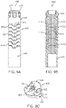
- FIG. 1A one simplified, example of a stented prosthetic heart valve 30 useful with systems, devices and methods of the present disclosure is illustrated in FIG. 1A .
- the prosthetic heart valve 30 is shown in a normal or expanded condition in the view of FIG. 1A;
- FIG. 1B illustrates the prosthetic heart valve in a compressed condition (e.g., when compressively retained within an outer catheter or sheath as described below).
- the prosthetic heart valve 30 includes a stent or stent frame 32 and a valve structure 34.
- the stent frame 32 can assume any of the forms mentioned above, and is generally constructed so as to be self-expandable from the compressed condition ( FIG. 1B ) to the normal, expanded condition ( FIG. 1A ).
- the valve structure 34 can assume a variety of forms, and can be formed, for example, from one or more biocompatible synthetic materials, synthetic polymers, autograft tissue, homograft tissue, xenograft tissue, or one or more other suitable materials.
- the valve structure 34 can be formed, for example, from bovine, porcine, equine, ovine and/or other suitable animal tissues.
- the valve structure 34 can be formed, for example, from heart valve tissue, pericardium, and/or other suitable tissue.
- the valve structure 34 can include or form one or more leaflets 36.
- the valve structure 34 can be in the form of a tri-leaflet bovine pericardium valve, a bi-leaflet valve, or another suitable valve.
- the valve structure 34 can comprise two or three leaflets that are fastened together at enlarged lateral end regions to form commissural joints, with the unattached edges forming coaptation edges of the valve structure 34.
- the leaflets 36 can be fastened to a skirt that in turn is attached to the frame 32.
- the upper ends of the commissure points can define an inflow portion 38 corresponding to a first or inflow end 40 of the prosthesis 30.
- the opposite end of the valve can define an outflow portion 42 corresponding to a second or outflow end 44 of the prosthesis 30.
- the stent frame 32 can have a lattice or cell-like structure, and optionally forms or provides crowns 46 and/or eyelets 48 (or other shapes) at the outflow and inflow ends 40, 44.
- the prosthetic heart valve 30 can be configured (e.g., sized and shaped) for replacing or repairing an aortic valve.
- other shapes are also envisioned, adapted to mimic the specific anatomy of the valve to be repaired (e.g., stented prosthetic heart valves useful with the present disclosure can alternatively be shaped and/or sized for replacing a native mitral, pulmonic or tricuspid valve).
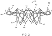
- FIG. 2 illustrates another example of a stent frame 50 portion of another prosthetic heart valve with which the systems, devices and methods of the present disclosure are useful. In the normal or expanded condition of FIG.
- the stent frame 50 can be sized and shaped for mitral valve implantation.
- the valve structure attached to the stent frame 50 defines an outflow portion 52 arranged at a first or outflow end 54, and an inflow portion 56 arranged at a second or inflow end 58.
- the inflow portion 56 can exhibit a more pronounced change in shape relative to the corresponding outflow portion 52.
- the stent frame 50 can be forced and constrained to a compressed condition (not shown, but akin to the shape of FIG. 1A ) during delivery, and will self-expand to the natural condition of FIG. 2 upon removal of the constraining force(s).
- the stent frame 50 is configured to be crimped to a diameter on the order of 12 mm during delivery, and will self-expand to the natural, expanded condition that includes the inflow portion 56 having a diameter on the order of 60 mm.
- crowns 60 and/or eyelets 62 optionally can be formed at one or both of the outflow and inflow ends 54, 58.
- the stent frame 50 can optionally include or carry additional structural components, such as support arm(s) 64.
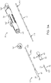
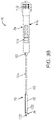
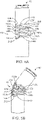
- FIGS. 3A and 3B one embodiment of a delivery device 70 for percutaneously delivering the prosthesis is shown in simplified form in FIGS. 3A and 3B .
- the delivery device 70 includes a delivery sheath assembly 72, an inner shaft assembly 74, an inner support assembly 76, a handle assembly 78, and a deflection assembly 80. Details on the various components are provided below. In general terms, however, the delivery device 70 combines with a stented prosthetic heart valve (not shown) to form a system for performing a therapeutic procedure on a defective heart valve of a patient.
- the delivery device 70 provides a loaded or delivery state in which a stented prosthetic heart valve is loaded over the inner support assembly 76 and is compressively retained within a capsule 82 of the delivery sheath assembly 72.
- the deflection assembly 80 (or the support assembly 76) can include or provide a valve retainer 84 configured to selectively receive a corresponding feature (e.g., posts) provided with the prosthetic heart valve stent frame.
- the delivery sheath assembly 72 can be manipulated to withdraw the capsule 82 proximally from over the prosthetic heart valve via operation of the handle assembly 78, permitting the prosthesis to self-expand and partially release from the inner support assembly 76.
- the deflection assembly 80 includes a hinge region 90.
- the hinge region 90 is operable to deflect or bend the corresponding segment of the delivery sheath assembly 72 (otherwise disposed over the hinge region 90) in a controlled fashion, effectuating a change in spatial orientation of the inner support assembly 76 (and thus the prosthesis and the capsule 82 when disposed over the inner support assembly 76) relative to the inner shaft assembly 74 and the handle assembly 78.
- the present disclosure is in no way limited to the delivery sheath assembly 72, the inner shaft assembly 74, the support assembly 76 or the handle assembly 78 as shown and described below. Any construction that generally facilitates compressed loading of a stented prosthetic heart valve over an inner shaft via a retractable outer sheath or capsule is acceptable.
- the delivery device 70 can optionally include additional components or features, such as a flush port assembly 92, or a recapture sheath (not shown),
- the delivery sheath assembly 72 defines proximal and distal ends 100, 102, and includes the capsule 82 and an outer shaft 104.
- the delivery sheath assembly 72 can be akin to a catheter, defining a lumen 106 (referenced generally) that extends from the distal end 102 through the capsule 82 and at least a portion of the outer shaft 104.
- the lumen 106 can be open at the proximal end 100 (e.g., the outer shaft 104 can be a tube).
- the capsule 82 extends distally from the outer shaft 104, and in some embodiments has a more stiffened construction (as compared to a stiffness of the outer shaft 104) that exhibits sufficient radial or circumferential rigidity to overtly resist the expected expansive forces of the stented prosthetic heart valve (not shown) when compressed within the capsule 82.
- the outer shaft 104 can be a polymer tube embedded with a metal braiding, whereas the capsule 82 includes a laser-cut metal tube that is optionally embedded within a polymer covering.
- the capsule 82 and the out shaft 104 can have a more uniform or even homogenous construction (e.g., a continuous polymer tube).
- the capsule 82 is constructed to compressively retain the stented prosthetic heart valve at a predetermined diameter when loaded within the capsule 82, and the outer shaft 104 serves to connect the capsule 82 with the handle assembly 78.
- the outer shaft 104 (as well as the capsule 82) is constructed to be sufficiently flexible for passage through a patient's vasculature, yet exhibits sufficient longitudinal rigidity to effectuate desired axial movement of the capsule 82.
- proximal retraction of the outer shaft 104 is directly transferred to the capsule 82 and causes a corresponding proximal retraction of the capsule 82.
- the outer shaft 104 is further configured to transmit a rotational force or movement onto the capsule 82.
- the inner shaft assembly 74 can have various constructions appropriate for supporting the delivery sheath assembly 72, including indirectly supporting the inner support assembly 76 (and a stented prosthetic heart valve disposed thereon) relative to the capsule 82.
- the inner shaft assembly 74 includes an intermediate shaft or tube 110 and a proximal shaft or tube 112.
- the intermediate tube 110 is optionally formed of a flexible polymer material (e.g., PEEK), and is sized to be slidably received within the delivery sheath assembly 72.
- the intermediate tube 110 serves as a transition to the deflection assembly 80, and in some embodiments is a flexible polymer tubing (e.g., PEEK) having a diameter slightly less than that of the proximal tube 112.
- the proximal tube 112 can have a more rigid construction, configured for robust assembly with the handle assembly 78, such as a metal hypotube. Other constructions are also envisioned.
- the intermediate and proximal tubes 110, 112 are integrally formed as a single, homogenous tube or shaft.
- the inner shaft assembly 74 forms or defines at least one lumen (not shown) sized, for example, to slidably receive a guide wire (not shown).
- the inner shaft assembly 74 can optionally form one or more additional lumens corresponding with one or more pull wire lumens provided with the deflection assembly 80 as described below.
- the inner support assembly 76 includes an inner support shaft 120 and a tip 122.
- the inner support shaft 120 is sized to be slidably received within the lumen 106 of the delivery sheath assembly 72, and is configured for mounting to the deflection assembly 80.
- the inner support shaft 120 can be a flexible polymer tube embedded with a metal braid. Other constructions are also acceptable so long as the inner support shaft 120 exhibits sufficient structural integrity to support a loaded, compressed stented prosthetic heart valve (not shown).
- the tip 122 forms or defines a nose cone having a distally tapering outer surface adapted to promote atraumatic contact with bodily tissue.
- the tip 122 can be fixed or slidable relative to the inner support shaft 120.
- the inner support assembly 76 can define a continuous lumen (not shown) sized to slidably receive an auxiliary component such as a guide wire (not shown).
- the handle assembly 78 generally includes a housing 140 and one or more actuator mechanisms 142 (referenced generally).
- the housing 140 maintains the actuator mechanism(s) 142, with the handle assembly 78 configured to facilitate sliding movement of the delivery sheath assembly 72 relative to other components (e.g., the inner shaft assembly 74, the support shaft assembly 76 and the deflection assembly 80).
- one or more of the actuator mechanisms 142 interfaces with, or is considered part of, the deflection assembly 80 and is operable by a user to effectuate bending or deflection of the hinge region 90 as described below.
- the housing 140 can have any shape or size appropriate for convenient handling by a user.
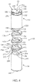
- the deflection assembly 80 includes a plurality of hinge segments 150, a leading hub 152 and a joiner hub 154.
- leading hub 152 can form or be connected to the valve retainer 84 that is otherwise configured to selectively engage with corresponding features of the stented prosthetic heart valve.
- the joiner hub 154 is configured for attachment to the inner shaft assembly 74 ( FIG. 3A ).
- the hinge segments 150 are disposed between the leading hub 152 and the joiner hub 154, are can be articulated relative one another via tensioning of a pull wire (not shown) in establishing the hinge region 90.
- FIG. 4 illustrates the deflection assembly 80 as including three of the hinge segments 150, any other number, greater or lesser, is also acceptable.
- the deflection assembly 80 includes a distal-most hinge segment 150a, a proximal-most hinge segment 150b, and one or more intermediate hinge segments 150c.
- the hinge segments 150 can assume a variety of forms, and in some embodiments are identical.
- Each of the hinge segments 150 can be a generally disc-shaped body, and defines a central bore 156.
- the hinge segment 150 further includes or defines opposing, proximal and distal major surfaces 160, 162 along with a platform region 164 and a capture region 166.
- the platform region 164 tapers in thickness from the capture region 166, extending from a pivot side or edge 170 to a clearance side or edge 172.
- the pivot edge 170 is proximate the capture region 166 whereas the clearance edge 172 is opposite the capture region 166.
- the major surfaces 160, 162 can be substantially flat or planar along the platform region 164, although the planes of the major surfaces 160, 162 are not parallel.
- each hinge segment 150 forms complimentary features for engaging with corresponding features of other ones of the hinge segments 150.
- the capture region 166 can form a spine 180 and opposing tabs 182 (one of which is visible in the views).
- the spine 180 represents a continuation of the distal major surface 162 from the platform region 164, whereas the tabs 182 are defined as projections in the proximal major surface 160 from the platform region 164.
- Grooves 184 are formed at opposite sides of the spine 180, with each groove 184 being aligned with a corresponding one of the tabs 182.
- the grooves 184 represent a recess in the distal major surface 162.
- a slot (hidden in the views) is formed between the tabs 182, aligned with the spine 180.
- the slot represents a recess in the proximal major surface 162.
- the grooves 184 are each sized and shaped to receive a respective one of the tabs 182 of an identically formed hinge segment 150.
- the slot is sized and shaped to receive the spine 180 of an identically formed hinge segment 150.
- one of the tabs 182c of the intermediate hinge segment 150c nests within a corresponding one of the grooves 184b of the proximal-most hinge segment 150b.
- one of the tabs 182a of the distal-most hinge segment 150a nests within a corresponding one of the grooves 184c of the intermediate hinge segment 150c.
- the spine 180c of the intermediate hinge segment 150c nests within the slot of the distal-most hinge segment 150a
- the spine 180b of the proximal-most hinge segment 150b nests within the slot of the intermediate hinge segment 150c.
- the central bores 156 ( FIG. 4 ) are aligned to permit passage of an object, such as a guide wire (not shown).
- an object such as a guide wire (not shown).
- a clearance gap 190 is established between the hinge segments 150a-150c along the platform regions 164. Due to the tapered shape of the platform regions 164, a size of the gaps 190 increases toward the corresponding clearance edges 172.
- the hinge segments 150a-150c are subjected to a tensioning force adjacent the clearance edges 172, the hinge segments 150a-150c are caused to articulate relative to one another, with each hinge segment 150a-150c pivoting relative to the immediately adjacent hinge segment 150a-150c at the pivot edges 170.
- the hinge region 90 collectively defined by the hinge segments 150a-150c deflects or forms a bend, as shown in FIG. 5B .
- This collective deflection or articulation can continue until the platform regions 164 are forced into contact with one another.
- the hinge region 90 is deflected to form a bend or curve having an interior curve or radius 200 (referenced generally) and an exterior curve or radius 202 (referenced generally).
- the interior curve 200 is collectively defined by the clearance edges 172.
- the exterior curve 202 is collectively defined by the capture regions 166.
- FIGS. 5A and 5B illustrate that the tab 182c of the intermediate hinge segment 150c slides within, but remains nested with, the corresponding groove 184b of the proximal-most hinge segment 150b; the spine 180c of the intermediate hinge segment 150c slides within, but remains nested with, the slot (referenced generally at 204) of the distal-most hinge segment 150a; etc.).
- the hinge region 90 can readily be reverted back from the deflected arrangement of FIG. 5B to the linear arrangement of FIG. 5A .
- each of the hinge segments 150 can define a pull wire lumen 210 adjacent the corresponding clearance edge 172 (e.g., between the central bore 156 and the clearance edge 172).
- the pull wire lumen 210 is open to the opposing major faces 160, 162, and is sized to slidably receive a pull wire (e.g., a small diameter wire, braided string, etc.).
- the pull wire is selected to be highly robust, capable of maintaining its structural integrity at the expected forces encountered during use (e.g., 150 N). Other constructions (e.g., multiple pull wires, etc.) are also acceptable.
- the leading hub 152 is a generally cylindrical body (with an outer diameter generally corresponding with that of each of the hinge segments 150) defining a trailing side 220 opposite a leading side 222.
- the trailing side 220 is configured to interface with the distal-most hinge segment 150a in an articulating manner akin to the articulating interface between immediately adjacent ones of the hinge segments 150 as described above.
- the trailing side 220 includes or forms proximally-projecting tabs 226 (one of which is visible in FIG. 4 ) sized and shaped to nest within a corresponding one of the grooves 184 formed by the distal-most hinge segment 150a.
- a slot (hidden in the view) is formed, configured to slidably receive the spine 180 of the distal-most hinge segment 150a.
- a trailing face 228 (referenced generally) of the leading hub 152 is substantially planar for interfacing with the distal major surface 162 of the distal-most hinge segment 150a. With this configuration, the leading hub 152 effectively serves as a continuation of the hinge region 90, as reflected in FIGS. 5A and 5B .
- the leading side 222 can assume various forms, and in some embodiments forms the valve retainer 84 (or portions thereof).
- the valve retainer 84 is generally configured in accordance with features of the stented prosthetic heart valve (and vice-versa), and is generally configured to assist in loading the prosthesis to the delivery device 70.
- the valve retainer 84 as formed by the leading hub 152, includes a head 230, a neck 232, and a shoulder 234.
- the neck 232 has a reduced diameter as compared to the head 230 and the shoulder 234, establishing a circumferential slot.
- various axial slots 236 can be provided.
- the slots 236 are configured to temporarily receive and retain posts or other features provided by the stented prosthetic heart valve.
- valve retainer 84 A number of other valve retention configurations are equally acceptable, and the present disclosure is in no way limited to the valve retainer 84 as shown. Further, while the valve retainer 84 has been shown as being part of the leading hub 152, in other embodiments, the valve retainer 84 (or portions thereof) can be provided with other components of the delivery device apart from the leading hub 152.
- the leading hub 152 can, in some embodiments, form a central bore 240 for slidably receiving a separate component, such as a guide wire (not shown). Upon final arrangement of the leading hub 152 relative to the hinge segments 150, the central bore 240 of the leading hub 152 is generally aligned with the central bore 156 of the distal-most hinge segment 150a for reasons made clear below. Further, the leading hub 152 can include or provide one or more features that facilitate assembly and/or operation of the mechanism utilized to apply deflection-causing tension on to the hinge region 90. For example, where the deflection assembly 80 incorporates one or more pull wires as described above, the leading hub 152 can define an axial pull wire lumen 250 at a location off-set from a center line of the leading hub 152.
- the pull wire lumen 250 of the leading hub 152 corresponds with the pull wire lumen 210 of each of the hinge segments 150.
- the pull wire lumen 250 of the leading hub 152 is generally aligned with the pull wire lumen 210 of the distal-most hinge segment 150a such that a pull wire readily extends between the distal-most hinge segment 150a and the leading hub 152.
- the joiner hub 154 is a generally cylindrical body (with an outer diameter generally corresponding with that of each of the hinge segments 150) defining a trailing side 260 opposite a leading side 262.
- the trailing side 260 is generally configured for assembly to another component of the delivery device 70, such as the intermediate shaft 110 ( FIG. 3A ).
- the joiner hub 154 can form an internally-threaded hole (not shown) at the trailing side 260 that promotes threaded attachment with the intermediate shaft 110.
- Other connection techniques are equally acceptable.
- the leading side 262 is configured to interface with the proximal-most hinge segment 150b in an articulating manner akin to the articulating interface between immediately adjacent ones of the hinge segments 150 as described above.
- the leading side 262 includes or forms a platform region 264 and a capture region 266.
- a distal face of the platform region 264 is substantially planar for interfacing with the proximal major surface 150 of the proximal-most hinge segment 150b.
- the capture region 266 includes or provides a spine 270 located between opposing grooves 272.
- the spine 270 is configured to be slidably received within the slot (hidden) of the proximal-most hinge segment 150b.
- the grooves 272 are each sized and shaped to receive a corresponding one of the tabs 182 of the proximal-most hinge segment 150b in a nested fashion. With this configuration, the joiner hub 154 effectively serves as a continuation of the hinge region 90, as reflected in FIGS. 5A and 5B .
- the joiner hub 154 can, in some embodiments, form a central bore 274 for slidably receiving a separate component, such as a guide wire (not shown). Upon final arrangement of the joiner hub 154 relative to the hinge segments 150, the central bore 274 of the joiner hub 154 is generally aligned with the central bore 156 of the proximal-most hinge segment 150b for reasons made clear below. Further, the joiner hub 154 can include or provide one or more features that facilitate assembly and/or operation of the mechanism utilized to apply deflection-causing tension on to the hinge region 90.
- the joiner hub 154 can define an axial pull wire lumen 276 at a location off-set from a center line of the joiner hub 154.
- the pull wire lumen 276 of the joiner hub 154 corresponds with the pull wire lumen 210 of each of the hinge segments 150.
- the pull wire lumen 276 of the joiner hub 154 is generally aligned with the pull wire lumen 210 of the proximal-most hinge segment 150b such that a pull wire readily extends between the joiner hub 154 and the proximal-most hinge segment 150b.
- the hinge segments 150, the leading hub 152, and the joiner hub 154 are, in some embodiments, formed of an identical or substantially identical material, such as a surgically safe plastic material.
- the hinge segments 150, the leading hub 152, and the joiner hub 154 are each formed as solid bodies, such as by a molding or machining process, with various features described above (e.g., tabs, grooves, spines, etc.) being molded or machined into the part. Regardless, each of the hinge segments 150 is discrete from one another, as well as from the leading hub 152 and the joiner hub 154.
- the components 150-154 of the deflection assembly 80 are each a solid body, are not hollow, and are not commonly formed from a homogenous tube (e.g., the components 150-154 are not cut (for example, laser cut) from a single metal tube).
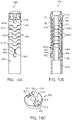
- FIG. 5A final construction of the deflection assembly 80 is shown in FIG. 5A (it being understood that the optional pull wire(s) is omitted from the view).
- the joiner hub 154, the hinge segments 150, and leading hub 152 are longitudinally arranged or aligned in a sequential or stacked fashion. Adjacent ones of the hinge segments 150 are connected so as to permit articulating movement of each hinge segments 150 relative to one another as described above.
- a similar articulating interface is established between the leading hub 152 and the distal-most hinge segment 150a (e.g., the tabs 226 of the leading hub 152 nest within respective ones of the grooves 184 formed by the distal-most hinge segment 150a).
- a similar articulating interface is further established between the proximal-most hinge segment 150b and the joiner hub 154 (e.g., the tabs 182 of the proximal-most hinge segment 150b nest within respective ones of the grooves 272 of the joiner hub 154).
- the deflection assembly 80 can be readily transitioned between the linear arrangement of FIG. 5A and the deflected arrangement of FIG. 5B .
- the central bores 156, 240, 274 are generally aligned with one another, such that an auxiliary component, such as a guide wire, can extend through the deflection assembly 80, with the auxiliary component being force to assume the shape of the hinge region 90 (i.e., when the deflection assembly 80 is deflected from the linear arrangement of FIG. 5A to the deflected arrangement of FIG. 5B , the guide wire or other auxiliary component extending through the central bores 156, 240, 274 will be forced to a similar shape, following a curvature collectively defined by the hinge region 90).
- an auxiliary component such as a guide wire
- the pull wire (not shown) can be received through the pull wire lumens 210, 250, 276 as described above.
- the pull wire(s) extends proximally from the joiner hub 154, for example to the handle assembly 78 ( FIGS. 3A and 3B ), and is connected to a user actuator.
- a distal end of the pull wire(s) is rigidly connected to the leading hub 152 (e.g., the distal end of the pull wire extends through pull wire lumen 250 of the leading hub 152 and is held (e.g., via a knot or other coupling body) at the leading side 222).
- a pulling or tensioning force applied to a proximal region of the pull wire(s) is transferred on to the leading hub 152, pulling or compressing the leading hub 152 toward the joiner hub 154 (that is otherwise held spatially stationary while tension is applied to the pull wire(s) via the inner shaft assembly 74 ( FIG. 3A )).
- the hinge segments 150 are compressed toward one another between the hubs 152, 154 and articulate, allowing the hinge region 90 to articulate to the deflected arrangement of FIG. 5B .
- the deflection assembly 80 is configured to be structurally robust such that any change in shape of the hinge region 90 is imparted on to any structure surrounding the hinge region 90.
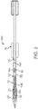
- FIG. 6 a simplified representation of portions of the delivery device 70 in the delivery state and loaded with the stented prosthetic heart valve 30 (referenced generally) to provide a system 300 for performing a therapeutic procedure on a defective heart valve is shown in FIG. 6 .
- the stent frame 32 of the prosthesis 30 is depicted in FIG. 6 .
- the stent frame 32 is crimped over the inner support shaft 120, and is compressibly held in the compressed condition by the capsule 82. Further, the stent frame 32 is connected to the valve retainer 84.
- the leading hub 152 is attached to the inner support shaft 120.
- the joiner hub 154 is attached to the intermediate shaft 110.
- the outer shaft 104 of the delivery sheath assembly 72 is coaxially received over the leading hub 152, the hinge segments 150, and the joiner hub 154.
- the hinge region 90 is caused to deflect or articulate from the linear arrangement shown to a deflected arrangement (as in FIG. 5B , for example)
- the outer shaft 104 conforms to or with the deflected shape defined along the hinge region 90.
- the leading hub 152 is spatially reoriented relative to the joiner hub 154; this movement, in turn, is transferred to the inner support shaft 120 and thus the prosthesis 30 carried thereon.
- the deflection assemblies of the present disclosure are capable of generating the above-described deflection even when disposed within a relatively large delivery sheath or catheter, for example a delivery sheath or catheter having an inner diameter on the order of 12-13 mm.
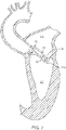
- FIG. 7 generally reflects use of the delivery device 70 in delivering a stented prosthetic heart valve (hidden) to a mitral valve target site 310.
- the mitral valve target site 310 separates the left atrium LA and the left ventricle LV.
- the delivery device 70 is shown after having been introduced into the vasculature via a percutaneous entry point (e.g., the Seldinger technique), and having been tracked through the vasculature and into the left atrium LA.
- the percutaneous entry point may be formed in a femoral vein.
- a guide wire (not shown) is advanced through the circulatory system, eventually arriving at the heart.
- the guide wire is directed into the right atrium, traverses the right atrium and is made to puncture, with the aid of a transeptal needle or pre-existing hole, the atrial septum, thereby entering the left atrium LA.
- the endoluminal entry port and the atrial septum are dilated to permit entry of a guide catheter (not shown) and/or the delivery device 70 into the left atrium LA.
- the deflection assembly 80 (referenced generally) is operated or caused to deflect to the deflected arrangement shown in FIG.
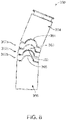
- FIG. 8 is a simplified view of portions of another embodiment defection assembly 350 in accordance with principles of the present disclosure.
- the deflection assembly 350 includes a plurality of hinge segments 352, a leading hub 354, and a joiner hub 356.
- tension-applying device e.g., one or more pull wires
- tension-applying device can also be included, but are omitted from the view for ease of illustration.
- the hinge segments 352 can be highly akin to the hinge segments 150 ( FIG. 4 ) described above, and generally include or form various complimentary features that promote an articulating interface between consecutively stacked or arranged ones of the hinge segments 352 (as well as between a distal-most hinge segment 352a and the leading hub 354, and between a proximal-most hinge segment 352b and the joiner hub 356).
- each of the hinge segments 352 can include or form opposing tabs 360 (one of which is visible in FIG. 8 ) and opposing grooves 362 (one of which is visible in FIG. 8 ).
- the tabs 360 and the grooves 362 have a complimentary size and shape, such that the tab 360 of one hinge segment is slidably received or nested with a corresponding groove 362 of an immediately adjacent hinge segment 350.
- the leading hub 354 and the joiner hub 356 form or provide corresponding interface features (e.g., the leading hub 354 forms opposing grooves 364 (one of which is visible in FIG. 8 ) for receiving a corresponding one of the tabs 360 of the distal-most hinge segment 352a, whereas the joiner hub 356 forms or provides opposing tabs 366 (one of which is visible in FIG. 8 ) sized to slidably nest within a corresponding one of the grooves 362 of the proximal-most hinge segment 352b.
- a hinged or articulating interface is established between adjacent ones of the components 352-356 upon final assembly, with the pivot point or line approximately intersecting an axial centerline of the corresponding component 352-356.
- the off-set pivot arrangement (as in FIG. 4 ) may be desired where an increased lever effect is of interest.
- the hinge segments 150, the leading hub 152 and the joiner hub 154 can be generally maintained relative to one another by the pull wire(s) or other tension-applying mechanism.
- the deflection assemblies of the present disclosure can include additional features that more directly join immediately adjacent ones of the components 150-154 relative to one another. As a point of reference, in some instances it may be desirable to limit separation of the components 150-156 relative to one another, for example when loading a stented prosthetic heart valve on to the delivery device 70. For example, and with additional reference to FIG.
- one loading technique entails holding the stented prosthetic heart valve 30 in a compressed condition while the delivery sheath assembly 72 is moved distally to sequentially direct the capsule 82 over the prosthesis 30. Under these circumstances, a tension or pulling force will be applied on to the leading hub 152 (e.g., as the capsule 82 is moved distally, the capsule 82 will tend to apply a distal force on to the prosthesis 30, and thus on to the leading hub 152). Absent a more robust connection between the leading hub 152 and the distal-most hinge segment 150 (as well as between immediately adjacent ones of the hinge segments 150, and between the proximal-most hinge segment 150 and the joiner hub 154), the components 150-154 might undesirably separate from one another.
- the deflection assembly 400 includes a plurality of hinge segments 402, a leading hub 404, and a joiner hub 406.
- the hinge segments 402 can be highly akin to the hinge segments 150 ( FIG. 4 ), and can incorporate any of the features described above.
- the leading hub 404 can be highly akin to the leading hub 152 ( FIG. 4 )
- the joiner hub 406 can be highly akin to the joiner hub 154 ( FIG. 4 ).
- the leading hub 404 can optionally form slots 407 for receiving respective components of a prosthetic heart valve (e.g., respective ones of the crowns 60 or eyelets 62 shown in FIG. 2 ). Regardless, an articulating interface is established between consecutive ones of the components 402-406 upon final assembly to collectively define a hinge region 408 as described above.
- the deflection assembly 400 includes one or more pins securing immediately adjacent ones of the components 402-406 to one another. For example, and as best shown in FIG. 9B , the leading hub 404 is connected to the distal-most hinge segment 402a by pins 410, 412.
- the pins 410, 412 are aligned with one another and arranged such that the leading hub 404 can articulate relative to the distal-most hinge segment 402a (and vice-versa), pivoting or rotating about the pins 410, 412. As shown, adjacent ones of the hinge segments 402 are similarly secured to one another by two pins 410, 412, respectively, as is the proximal-most hinge segment 402b to the joiner hub 406.
- the pins 410, 412 can be assembled to the corresponding components 402-406 in a variety of manners.
- the components 402-406 can be formed to define holes into which the pins 410, 412 are rotatably mounted.
- FIG. 9C illustrates one of the hinge segments 402 in greater detail.
- the hinge segment 402 can form or provide opposing tabs 420 (one of which is visible in the view) and opposing grooves 422.
- a central bore 424 is optionally provided, as is an optional pull wire lumen(s) 426.
- the hinge segment 402 forms a first hole 428 within or at each of the grooves 422, and a second hole 430 at or along each of the tabs 420 (it being understood that in the view of FIG. 9C , only one set of the holes 428, 430 is visible).
- a first one of the hinge segments 402 to a second one of the hinge segments 402 (e.g., in which the tabs 420 of the first hinge segment 402 nest within the grooves 422 of the second hinge segment)
- corresponding ones of the holes 428, 430 will be aligned and can readily receive a corresponding one of the pins 410, 412 ( FIG. 9B ).
- the leading hub 404 and the joiner hub 406 can provide similar features or holes.
- the hinge region 408 can articulate or deflect in accordance with previous descriptions (e.g., in response to a compressive force applied to the leading hub 404 in a direction of the joiner hub 406). Further, when placed in tension (e.g., a distal pulling force applied to the leading hub 404 while the joiner hub 406 is held stationary), the pins 410, 412 prevent the deflection assembly 400 from pulling apart.
- the deflection assembly 450 includes a plurality of hinge segment 452, a leading hub 454, and a joiner hub 456.
- the hinge segments 452 can be highly akin to the hinge segments 150 ( FIG. 4 ), and can incorporate any of the features described above.
- the leading hub 454 can be highly akin to the leading hub 152 ( FIG. 4 )
- the joiner hub 456 can be highly akin to the joiner hub 154 ( FIG. 4 ).
- an articulating interface is established between consecutive ones of the components 452-456 upon final assembly to collectively define a hinge region 458 as described above.
- the deflection assembly 450 includes one or more wires securing immediately adjacent ones of the components 452-456 to one another.
- FIG. 10A illustrates a first wire 460 extending between the leading hub 454 and the joiner hub 456, and interconnected with each of the hinge segments 452.
- a second wire 462 is similarly connected to the components 452-456 opposite the first wire 460.
- the wires 460, 462 are aligned with one another and arranged such that the leading hub 454 can articulate relative to the distal-most hinge segment 452a (and vice-versa), adjacent ones of the hinge segments 452 can articulate relative to one another, and the proximal-most hinge segment 452b to the joiner hub 456 (and vice-versa).
- the wires 460, 462 are affixed to the leading hub 454 and the joiner hub 456, and thus retain the components 452-456 as a collective unit.
- the wires 460, 462 can be formed of various, structurally robust materials (e.g., steel) and can be assembled to the corresponding components 452-456 in a variety of manners.
- the leading hub 454 can form opposing pockets 470, 472 each open to a corresponding wire lumen 474, 476.
- a crimp 480 is formed at, or attached to, a distal end of the first wire 460.
- the crimp 480 is sized and shaped to dock or lodge within the first pocket 470.
- a similar assembly is provided for the second wire 462 relative to the second pocket 472.
- the first wire 460 is then fed through the first wire lumen 474 (and the second wire 462 through the second wire lumen 476).
- FIG. 10C illustrates one of the hinge segments 452 in greater detail.
- the hinge segment 452 can form or provide opposing tabs 500, 502 and opposing grooves 504, 506.
- a central bore 508 is optionally provided, as is an optional pull wire lumen(s) 510.
- the hinge segment 452 forms a first wire lumen 512 through the first tab 500, and a second wire lumen 514 through the second tab 502.
- a first one of the hinge segments 452 Upon stacked arrangement of a first one of the hinge segments 452 to a second one of the hinge segments 452 (e.g., in which the tabs 500, 502 of the first hinge segment 452 nest within the grooves 504, 506, respectively, of the second hinge segment 452), corresponding ones of the wire lumens 512, 514 will be aligned and can readily receive a corresponding one of the wires 460, 462 ( FIGS. 10A and 10B ). Construction of the deflection assembly 450 thus entails advancing the first wire 460 (otherwise attached to the leading hub 454 as described above) through the first wire lumen 512 of each of the aligned hinge segments 452, and advancing the second wire 462 through the second wire lumen 514.
- the crimp 494 is then attached to the proximal end of the first wire 460 and docked to the first notch 490 of the joiner hub 456 (and the crimp 494 attached to the proximal end of the second wire 462 is docked to the second notch 492).
- the hinge region 458 can articulate or deflect in accordance with previous descriptions (e.g., in response to a compressive force applied to the leading hub 454 in a direction of the joiner hub 456). Further, when placed in tension (e.g., a distal pulling force applied to the leading hub 454 while the joiner hub 456 is held stationary), the wires 460, 462 prevent the deflection assembly 450 from pulling apart.
- the deflection assembly 550 includes a plurality of hinge segment 552, a leading hub 554, and a joiner hub 556.
- the hinge segments 552 can be highly akin to the hinge segments 150 ( FIG. 4 ), and can incorporate any of the features described above.
- the leading hub 554 can be highly akin to the leading hub 152 ( FIG. 4 )
- the joiner hub 556 can be highly akin to the joiner hub 154 ( FIG. 4 ).
- an articulating interface is established between consecutive ones of the components 552-556 upon final assembly to collectively define a hinge region 558 as described above.
- the deflection assembly 550 includes one or more wires securing immediately adjacent ones of the components 552-556 to one another.
- FIG. 11A illustrates a first wire 560 extending between the leading hub 554 and the joiner hub 556, and interconnected with each of the hinge segments 552.
- a second wire 562 is similarly connected to the components 552-556 opposite the first wire 560.
- the wires 560, 562 are aligned with one another and arranged such that the leading hub 554 can articulate relative to the distal-most hinge segment 552a (and vice-versa), adjacent ones of the hinge segments 552 can articulate relative to one another, and the proximal-most hinge segment 552b to the joiner hub 556 (and vice-versa).
- the wires 560, 562 are affixed to the leading hub 554 and the joiner hub 556, and thus retain the components 552-556 as a collective unit.
- the wires 560, 562 can be formed of various, structurally robust materials (e.g., steel) and can be assembled to the corresponding components 552-556 in a variety of manners.
- the leading hub 554 can form opposing pockets 570, 572 each open to a corresponding wire lumen 574, 576.
- the joiner hub 556 can include opposing slots 580, 582 that each generates a finger 584, 586.
- FIG. 11C illustrates one of the hinge segments 552 in greater detail.
- the hinge segment 552 can form or provide opposing tabs 600, 602 and opposing grooves 604, 606.
- a central bore 608 is optionally provided, as is an optional pull wire lumen(s) 610.
- the hinge segment 552 forms a first wire lumen 612 through the first tab 600, and a second wire lumen 614 through the second tab 602.
- first one of the hinge segments 552 to a second one of the hinge segments 552 (e.g., in which the tabs 600, 602 of the first hinge segment 552 nest within the grooves 604, 606, respectively, of the second hinge segment 552)
- corresponding ones of the wire lumens 612,614 will be aligned and can readily receive a corresponding one of the wires 560, 562 ( FIGS. 11A and 11B ).
- Construction of the deflection assembly 550 can generally entail forming a knot or a crimp in the distal end of each of the wires 560, 562, and then docking the so-formed distal end in the corresponding pocket 570, 572 of the leading hub 554.
- Glue or other adhesive can optionally be applied to the loaded distal end to prevent the wire 560, 562 from unraveling.
- the first wire 560 is advanced through the first wire lumen 612 of each of the aligned hinge segments 552, and the second wire 562 is advanced through the second wire lumens 614.
- the first wire 560 is guided through the first slot 580 and secured against the first finger 584 of the joiner hub 556.
- the second wire 562 is similarly connected to the second finger 586.
- Glue or other adhesive can optionally be applied to further secure the wires 560, 562 to the corresponding finger 584, 586.
- the hinge region 558 can articulate or deflect in accordance with previous descriptions (e.g., in response to a compressive force applied to the leading hub 554 in a direction of the joiner hub 556). Further, when placed in tension (e.g., a distal pulling force applied to the leading hub 554 while the joiner hub 556 is held stationary), the wires 560, 562 prevent the deflection assembly 550 from pulling apart.
- the delivery devices, systems and methods of the present disclosure provide a marked improvement over previous designs.
- the delivery device By providing the delivery device with a robust deflection assembly coaxially within the delivery sheath and immediately proximal the loaded stented prosthetic heart valve, the delivery device can be readily operated to effectuate desired bends or deflections commensurate with a desired delivery path presented by the anatomy of the particular procedure, even with more rigid or large outer sheath or catheter designs.
Landscapes
- Health & Medical Sciences (AREA)
- Cardiology (AREA)
- Engineering & Computer Science (AREA)
- Biomedical Technology (AREA)
- Life Sciences & Earth Sciences (AREA)
- Veterinary Medicine (AREA)
- General Health & Medical Sciences (AREA)
- Heart & Thoracic Surgery (AREA)
- Public Health (AREA)
- Animal Behavior & Ethology (AREA)
- Transplantation (AREA)
- Oral & Maxillofacial Surgery (AREA)
- Vascular Medicine (AREA)
- Hematology (AREA)
- Pulmonology (AREA)
- Biophysics (AREA)
- Anesthesiology (AREA)
- Mechanical Engineering (AREA)
- Prostheses (AREA)
Claims (15)
- Dispositif de délivrance (70) permettant d'implanter une valvule cardiaque prothétique à endoprothèse (30), le dispositif comprenant :une gaine externe (104) ;un arbre interne (110) disposé à l'intérieur de la gaine externe (104) ;un ensemble de déflexion (80, 400, 450, 550) fixé à l'arbre interne (110) et comportant :une pluralité de segments charnières (150, 352, 402, 452, 552) comportant un segment charnière le plus proximal (150b, 352b, 402b, 452b, 552b) et un segment charnière le plus distal (150a, 352a, 402a, 452a, 552a),un moyeu de jonction (154, 356, 406, 456, 566) relié à l'arbre interne (110) et s'interfaçant avec le segment charnière le plus proximal (150b, 352b, 402b, 452b, 552b), etun moyeu avant (152, 404, 454, 554) s'interfaçant avec le segment charnière le plus distal (150a, 352a, 402a, 452a, 552a) ; etun arbre de support (120) fixé à et s'étendant distalement du moyeu avant (152, 404, 454, 554) ;dans lequel le dispositif de délivrance (70) est conçu pour fournir un état chargé dans lequel une valvule cardiaque prothétique à endoprothèse (30) est comprimée par-dessus l'arbre de support (120) et retenue à l'intérieur d'une capsule (82) de la gaine externe (104) ;et dans lequel en outre une région charnière (90, 408, 458, 558) de l'ensemble de déflexion (80, 400, 450, 550) est conçue pour être défléchie par un utilisateur pour changer une orientation spatiale de l'arbre de support (120) par rapport à l'arbre interne (110) alors que le dispositif de délivrance (70) est à l'état chargé.
- Dispositif de délivrance (70) selon la revendication 1, dans lequel la pluralité de segments charnières est une pluralité de segments charnières empilés (150, 352, 402, 452, 552), dans lequel chacun des segments charnières (150, 352, 402, 452, 552) est formé de manière séparée comme un corps solide, et a des caractéristiques de mise en prise complémentaires (182, 184, 226, 272, 360, 362, 366, 364, 420, 422, 500, 502, 504, 506, 600, 602, 604, 606) par lesquelles des segments immédiatement adjacents des segments charnières (150, 352, 402, 452, 552) s'interfacent et peuvent s'articuler les uns par rapport aux autres.
- Dispositif de délivrance (70) selon la revendication 2, dans lequel les caractéristiques de mise en prise complémentaires (182, 184, 226, 272, 360, 362, 366, 364, 420, 422, 500, 502, 504, 506, 600, 602, 604, 606) comportent une première languette (500, 600) et une première rainure (504, 604), dans lequel éventuellement chacun des segments charnières (150, 352, 402, 452, 552) définit des première et seconde surfaces principales opposées (160, 162), et dans lequel en outre la première languette (500, 600) est formée comme une saillie le long de la première surface principale (160) et la première rainure (504, 604) est formée comme un évidement dans la seconde surface principale (162).
- Dispositif de délivrance (70) selon la revendication 3, dans lequel la pluralité de segments charnières empilés (150, 352, 402, 452, 552) comporte en outre des premier et second segments charnières intermédiaires (150c), et dans lequel en outre la première languette (500, 600) du premier segment charnière intermédiaire (150c) est emboîtée à l'intérieur de la première rainure (504, 604) du second segment charnière intermédiaire (150c).
- Dispositif de délivrance (70) selon la revendication 3, dans lequel la première rainure (504, 604) est ouverte sur un côté du segment charnière correspondant.
- Dispositif de délivrance (70) selon la revendication 3, dans lequel les caractéristiques de mise en prise complémentaires comportent en outre une second languette et une seconde rainure ; dans lequel éventuellement chacun des segments charnières (150, 352, 402, 452, 552) définit des première et seconde surfaces principales opposées (160, 162), et dans lequel en outre les première et seconde languettes (500, 502, 600, 602) sont formées comme des saillies le long de la première surface principale (160), et les première et seconde rainures (504, 506, 604, 606) sont formées comme des évidements dans la seconde surface principale (162) ;
dans lequel éventuellement la pluralité de segments charnières empilés (150, 352, 402, 452, 552) comporte en outre des premier et second segments charnières intermédiaires (150c), et dans lequel en outre les première et seconde languettes (500, 502, 600, 602) du premier segment charnière intermédiaire (150c) sont emboîtées dans les première et seconde rainures (504, 506, 604, 606), respectivement du second segment charnière intermédiaire (150c). - Dispositif de délivrance (70) selon la revendication 1, dans lequel chacun des segments charnières empilés (150, 352, 402, 452, 552), le moyeu de jonction (154, 356, 406, 456, 566) et le moyeu avant (152, 404, 454, 554) définissent un alésage central (156, 240, 274) pour recevoir de manière coulissante un fil guide ; éventuellement le dispositif de délivrance (70) comprenant en outre un fil de traction fixé au moyeu avant (152, 404, 454, 554) et s'étendant à travers chacun des segments d'articulation (150, 352, 402, 452, 552) et le moyeu de jonction (154, 356, 406, 456, 566) à l'écart de l'alésage central (156, 240, 274) correspondant.
- Dispositif de délivrance (70) selon la revendication 1, dans lequel le segment charnière le plus proximal (150b, 352b, 402b, 452b, 552b) est fixé de manière pivotante au moyeu de jonction (154, 356, 406, 456, 566) par au moins une première broche (410, 412).
- Dispositif de délivrance (70) selon la revendication 1, comprenant en outre un premier fil (460) ayant des première et seconde extrémités opposées, dans lequel le fil s'étend à travers chacun des segments charnières (150, 352, 402, 452, 552), et dans lequel en outre la première extrémité est fixée au moyeu avant (152, 404, 454, 554) et la seconde extrémité est fixée au moyeu de jonction (154, 356, 406, 456, 566).
- Dispositif de délivrance (70) selon la revendication 1, dans lequel l'ensemble de déflexion (80, 400, 450, 550) est conçu pour être déplacé de manière répétée entre un agencement linéaire et un agencement défléchi, et dans lequel en outre l'agencement linéaire comporte un espace de dégagement (190) défini entre des segments immédiatement adjacents des segments charnières (150, 352, 402, 452, 552) au niveau d'un côté de ceux-ci.
- Dispositif de délivrance (70) selon la revendication 1, dans lequel le moyeu avant (152, 404, 454, 554) comporte un dispositif de retenue de valvule qui comporte éventuellement une première fente conçue pour recevoir une partie d'une endoprothèse d'une valvule cardiaque prothétique (30).
- Système de traitement d'une valvule cardiaque défectueuse (30), le système comprenant le dispositif de délivrance (70) selon l'une quelconque des revendications précédentes, dans lequel
une valvule cardiaque prothétique (30) est comprimée par-dessus l'arbre de support (120) et retenue à l'intérieur d'une capsule (82) de la gaine externe (104) à l'état chargé. - Système selon la revendication 12, comprenant en outre :
un fil guide reçu de manière coulissante à l'intérieur d'un alésage central (156, 240, 274) de chacun des segments charnières (150, 352, 402, 452, 552), du moyeu de jonction (154, 356, 406, 456, 566) et du moyeu avant (152, 404, 454, 554). - Système selon la revendication 12, dans lequel la valvule cardiaque prothétique (30) est fixée sélectivement à un dispositif de retenue de valvule (84) du moyeu avant (152, 404, 454, 554) à l'état chargé ; dans lequel éventuellement la valvule cardiaque prothétique (30) comporte un cadre d'endoprothèse (32), et dans lequel en outre le dispositif de retenue de valvule (84) comporte une fente (236, 407) dimensionnée pour recevoir sélectivement une partie du cadre d'endoprothèse (32).
- Système selon la revendication 12, dans lequel les caractéristiques de mise en prise complémentaires comportent une première languette (500, 600) et une première rainure (504, 604).
Applications Claiming Priority (3)
| Application Number | Priority Date | Filing Date | Title |
|---|---|---|---|
| US201461980930P | 2014-04-17 | 2014-04-17 | |
| EP15717768.4A EP3131503B1 (fr) | 2014-04-17 | 2015-04-08 | Système de délivrance de valvule cardiaque prothétique à transcathéter à charnière |
| PCT/US2015/024982 WO2015160598A1 (fr) | 2014-04-17 | 2015-04-08 | Système de délivrance de valvule cardiaque prothétique à transcathéter à charnière |
Related Parent Applications (1)
| Application Number | Title | Priority Date | Filing Date |
|---|---|---|---|
| EP15717768.4A Division EP3131503B1 (fr) | 2014-04-17 | 2015-04-08 | Système de délivrance de valvule cardiaque prothétique à transcathéter à charnière |
Publications (2)
| Publication Number | Publication Date |
|---|---|
| EP3552585A1 EP3552585A1 (fr) | 2019-10-16 |
| EP3552585B1 true EP3552585B1 (fr) | 2022-10-26 |
Family
ID=52992014
Family Applications (2)
| Application Number | Title | Priority Date | Filing Date |
|---|---|---|---|
| EP15717768.4A Active EP3131503B1 (fr) | 2014-04-17 | 2015-04-08 | Système de délivrance de valvule cardiaque prothétique à transcathéter à charnière |
| EP19178780.3A Active EP3552585B1 (fr) | 2014-04-17 | 2015-04-08 | Système de délivrance de valvule cardiaque prothétique à transcathéter à charnière |
Family Applications Before (1)
| Application Number | Title | Priority Date | Filing Date |
|---|---|---|---|
| EP15717768.4A Active EP3131503B1 (fr) | 2014-04-17 | 2015-04-08 | Système de délivrance de valvule cardiaque prothétique à transcathéter à charnière |
Country Status (4)
| Country | Link |
|---|---|
| US (1) | US10368989B2 (fr) |
| EP (2) | EP3131503B1 (fr) |
| CN (1) | CN106170270B (fr) |
| WO (1) | WO2015160598A1 (fr) |
Cited By (11)
| Publication number | Priority date | Publication date | Assignee | Title |
|---|---|---|---|---|
| US11737872B2 (en) | 2018-11-08 | 2023-08-29 | Neovasc Tiara Inc. | Ventricular deployment of a transcatheter mitral valve prosthesis |
| US11779742B2 (en) | 2019-05-20 | 2023-10-10 | Neovasc Tiara Inc. | Introducer with hemostasis mechanism |
| US11793640B2 (en) | 2017-08-25 | 2023-10-24 | Neovasc Tiara Inc. | Sequentially deployed transcatheter mitral valve prosthesis |
| US11931254B2 (en) | 2019-06-20 | 2024-03-19 | Neovasc Tiara Inc. | Low profile prosthetic mitral valve |
| US11998447B2 (en) | 2019-03-08 | 2024-06-04 | Neovasc Tiara Inc. | Retrievable prosthesis delivery system |
| US12036117B2 (en) | 2019-04-10 | 2024-07-16 | Neovasc Tiara Inc. | Prosthetic valve with natural blood flow |
| US12053369B2 (en) | 2011-11-23 | 2024-08-06 | Neovasc Tiara Inc. | Sequentially deployed transcatheter mitral valve prosthesis |
| US12109111B2 (en) | 2015-12-15 | 2024-10-08 | Neovasc Tiara Inc. | Transseptal delivery system |
| US12138159B2 (en) | 2012-02-14 | 2024-11-12 | Neovasc Tiara Inc. | Methods and apparatus for engaging a valve prosthesis with tissue |
| US12193932B2 (en) | 2016-01-29 | 2025-01-14 | Neovasc Tiara Inc. | Prosthetic valve for avoiding obstruction of outflow |
| US12201524B2 (en) | 2016-11-21 | 2025-01-21 | Neovasc Tiara Inc. | Methods and systems for rapid retraction of a transcatheter heart valve delivery system |
Families Citing this family (118)
| Publication number | Priority date | Publication date | Assignee | Title |
|---|---|---|---|---|
| CA2554595C (fr) | 2004-02-03 | 2016-03-29 | Atria Medical Inc. | Dispositif et procede de controle de la pression in vivo |
| CA2848445C (fr) | 2004-09-14 | 2016-10-25 | Edwards Lifesciences Ag | Dispositif et procede de traitement de la regurgitation valvulaire |
| WO2006041505A1 (fr) | 2004-10-02 | 2006-04-20 | Huber Christoph Hans | Procedes et dispositifs de reparation ou de remplacement de valvules cardiaques ou du tissu contigu sans necessiter une assistance cardio-pulmonaire totale |
| AU2006315812B2 (en) | 2005-11-10 | 2013-03-28 | Cardiaq Valve Technologies, Inc. | Balloon-expandable, self-expanding, vascular prosthesis connecting stent |
| WO2008013915A2 (fr) | 2006-07-28 | 2008-01-31 | Arshad Quadri | Prothèse à valve percutanée et système et procédé pour implanter une telle prothèse |
| US20090276040A1 (en) | 2008-05-01 | 2009-11-05 | Edwards Lifesciences Corporation | Device and method for replacing mitral valve |
| CA2749026C (fr) | 2008-09-29 | 2018-01-09 | Impala, Inc. | Valvule cardiaque |
| EP4321134A3 (fr) | 2008-11-21 | 2024-05-01 | Percutaneous Cardiovascular Solutions Pty Limited | Prothèse de valvule cardiaque et procédé |
| AU2010236288A1 (en) | 2009-04-15 | 2011-10-20 | Cardiaq Valve Technologies, Inc. | Vascular implant and delivery system |
| NZ624106A (en) | 2009-04-29 | 2015-12-24 | Cleveland Clinic Foundation | Apparatus and method for replacing a diseased cardiac valve |
| US9034034B2 (en) | 2010-12-22 | 2015-05-19 | V-Wave Ltd. | Devices for reducing left atrial pressure, and methods of making and using same |
| US12453626B2 (en) | 2009-05-04 | 2025-10-28 | V-Wave Ltd. | Shunt for redistributing atrial blood volume |
| US8652203B2 (en) | 2010-09-23 | 2014-02-18 | Cardiaq Valve Technologies, Inc. | Replacement heart valves, delivery devices and methods |
| US8449599B2 (en) | 2009-12-04 | 2013-05-28 | Edwards Lifesciences Corporation | Prosthetic valve for replacing mitral valve |
| US8579964B2 (en) | 2010-05-05 | 2013-11-12 | Neovasc Inc. | Transcatheter mitral valve prosthesis |
| CA2803149C (fr) | 2010-06-21 | 2018-08-14 | Impala, Inc. | Prothese de valvule cardiaque |
| US12502276B2 (en) | 2011-05-16 | 2025-12-23 | Edwards Lifesciences Corporation | Inversion delivery device and method for a prosthesis |
| US11135054B2 (en) | 2011-07-28 | 2021-10-05 | V-Wave Ltd. | Interatrial shunts having biodegradable material, and methods of making and using same |
| US9668859B2 (en) | 2011-08-05 | 2017-06-06 | California Institute Of Technology | Percutaneous heart valve delivery systems |
| US9345573B2 (en) | 2012-05-30 | 2016-05-24 | Neovasc Tiara Inc. | Methods and apparatus for loading a prosthesis onto a delivery system |
| US9439763B2 (en) | 2013-02-04 | 2016-09-13 | Edwards Lifesciences Corporation | Prosthetic valve for replacing mitral valve |
| US20140277427A1 (en) | 2013-03-14 | 2014-09-18 | Cardiaq Valve Technologies, Inc. | Prosthesis for atraumatically grasping intralumenal tissue and methods of delivery |
| US9730791B2 (en) | 2013-03-14 | 2017-08-15 | Edwards Lifesciences Cardiaq Llc | Prosthesis for atraumatically grasping intralumenal tissue and methods of delivery |
| WO2014144247A1 (fr) | 2013-03-15 | 2014-09-18 | Arash Kheradvar | Mécanisme de poignée et fonctionnalité permettant de repositionner et d'extraire des valvules cardiaques transcathéter |
| US9572665B2 (en) | 2013-04-04 | 2017-02-21 | Neovasc Tiara Inc. | Methods and apparatus for delivering a prosthetic valve to a beating heart |
| EP3107497B1 (fr) | 2014-02-21 | 2020-07-22 | Edwards Lifesciences CardiAQ LLC | Dispositif d'acheminement pour le déploiement maîtrisé d'une de valvule de substitution |
| CA3161000A1 (fr) | 2014-05-19 | 2015-11-26 | Edwards Lifesciences Cardiaq Llc | Valvule mitrale de remplacement ayant un rabat annulaire |
| US9532870B2 (en) | 2014-06-06 | 2017-01-03 | Edwards Lifesciences Corporation | Prosthetic valve for replacing a mitral valve |
| CA2962747C (fr) | 2014-09-28 | 2023-02-28 | Cardiokinetix, Inc. | Appareils permettant de traiter un dysfonctionnement cardiaque |
| US10531951B2 (en) | 2014-11-26 | 2020-01-14 | Edwards Lifesciences Corporation | Transcatheter prosthetic heart valve and delivery system |
| US10751064B2 (en) | 2015-03-20 | 2020-08-25 | Edwards Lifescience Corporation | Systems and methods for delivering an implantable device |
| US10376363B2 (en) | 2015-04-30 | 2019-08-13 | Edwards Lifesciences Cardiaq Llc | Replacement mitral valve, delivery system for replacement mitral valve and methods of use |
| US10226335B2 (en) | 2015-06-22 | 2019-03-12 | Edwards Lifesciences Cardiaq Llc | Actively controllable heart valve implant and method of controlling same |
| US10092400B2 (en) | 2015-06-23 | 2018-10-09 | Edwards Lifesciences Cardiaq Llc | Systems and methods for anchoring and sealing a prosthetic heart valve |
| US10117744B2 (en) | 2015-08-26 | 2018-11-06 | Edwards Lifesciences Cardiaq Llc | Replacement heart valves and methods of delivery |
| US10575951B2 (en) | 2015-08-26 | 2020-03-03 | Edwards Lifesciences Cardiaq Llc | Delivery device and methods of use for transapical delivery of replacement mitral valve |
| US10350066B2 (en) | 2015-08-28 | 2019-07-16 | Edwards Lifesciences Cardiaq Llc | Steerable delivery system for replacement mitral valve and methods of use |
| US10376364B2 (en) * | 2015-11-10 | 2019-08-13 | Edwards Lifesciences Corporation | Implant delivery capsule |
| US11833034B2 (en) | 2016-01-13 | 2023-12-05 | Shifamed Holdings, Llc | Prosthetic cardiac valve devices, systems, and methods |
| CN109152641B (zh) * | 2016-06-02 | 2020-08-21 | 美敦力瓦斯科尔勒公司 | 具有隔膜孔闭合末端组件的经导管瓣膜递送系统 |
| US10350062B2 (en) | 2016-07-21 | 2019-07-16 | Edwards Lifesciences Corporation | Replacement heart valve prosthesis |
| AU2017301399B2 (en) * | 2016-07-28 | 2019-05-16 | Cook Medical Technologies Llc | Distal wire securement in steerable catheter |
| CN109789017B (zh) | 2016-08-19 | 2022-05-31 | 爱德华兹生命科学公司 | 用于置换二尖瓣的可转向递送系统和使用方法 |
| US10368988B2 (en) | 2016-11-09 | 2019-08-06 | Medtronic Vascular, Inc. | Valve delivery system having an integral displacement component for managing chordae tendineae in situ and methods of use thereof |
| US10493248B2 (en) | 2016-11-09 | 2019-12-03 | Medtronic Vascular, Inc. | Chordae tendineae management devices for use with a valve prosthesis delivery system and methods of use thereof |
| PT3554424T (pt) * | 2016-12-16 | 2023-04-03 | Edwards Lifesciences Corp | Sistemas, ferramentas e métodos de implantação para a aplicação de um dispositivo de ancoragem a uma válvula prostética |
| US10653523B2 (en) | 2017-01-19 | 2020-05-19 | 4C Medical Technologies, Inc. | Systems, methods and devices for delivery systems, methods and devices for implanting prosthetic heart valves |
| US10561495B2 (en) | 2017-01-24 | 2020-02-18 | 4C Medical Technologies, Inc. | Systems, methods and devices for two-step delivery and implantation of prosthetic heart valve |
| US11291807B2 (en) | 2017-03-03 | 2022-04-05 | V-Wave Ltd. | Asymmetric shunt for redistributing atrial blood volume |
| US12029647B2 (en) | 2017-03-07 | 2024-07-09 | 4C Medical Technologies, Inc. | Systems, methods and devices for prosthetic heart valve with single valve leaflet |
| AU2018231116A1 (en) | 2017-03-09 | 2019-09-19 | Medtronic Inc. | Stented prosthesis delivery devices having steering capabilities and methods |
| US10716668B2 (en) | 2017-04-05 | 2020-07-21 | Medtronic, Inc. | Delivery system with anchoring nosecone and method of delivery |
| US20180303488A1 (en) | 2017-04-20 | 2018-10-25 | Medtronic, Inc. | Stabilization of a transseptal delivery device |
| US12036113B2 (en) | 2017-06-14 | 2024-07-16 | 4C Medical Technologies, Inc. | Delivery of heart chamber prosthetic valve implant |
| WO2019010321A1 (fr) | 2017-07-06 | 2019-01-10 | Edwards Lifesciences Corporation | Système de pose de rail maniable |
| EP3654885B1 (fr) | 2017-07-18 | 2024-03-06 | Medtronic Vascular Inc. | Système de pose de valvule cardiaque prothétique par transcathéter avec ensemble de coupe distal |
| CN107496055B (zh) * | 2017-08-10 | 2021-06-08 | 上海微创心通医疗科技有限公司 | 心脏瓣膜输送导管及输送系统 |
| WO2019040781A1 (fr) | 2017-08-24 | 2019-02-28 | Medtronic Vascular, Inc. | Système d'administration trans-septale ayant un segment de déviation et procédés d'utilisation |
| US11071846B2 (en) | 2017-09-14 | 2021-07-27 | Medtronic Vascular, Inc. | Deflection catheter for aiding in bending of a catheter |
| US20190091021A1 (en) * | 2017-09-22 | 2019-03-28 | St. Jude Medical, Cardiology Division, Inc. | Articulating Retainer For Transcatheter Heart Valve Delivery Systems |
| JP7237955B2 (ja) * | 2017-10-18 | 2023-03-13 | エドワーズ ライフサイエンシーズ コーポレイション | カテーテルアセンブリ |
| US10806574B2 (en) | 2017-11-20 | 2020-10-20 | Medtronic Vascular, Inc. | Delivery systems having a temporary valve and methods of use |
| US10898698B1 (en) | 2020-05-04 | 2021-01-26 | V-Wave Ltd. | Devices with dimensions that can be reduced and increased in vivo, and methods of making and using the same |
| WO2019142152A1 (fr) | 2018-01-20 | 2019-07-25 | V-Wave Ltd. | Dispositifs et procédés pour fournir un passage entre des chambres cardiaques |
| CN117481869A (zh) | 2018-01-25 | 2024-02-02 | 爱德华兹生命科学公司 | 在部署后用于辅助置换瓣膜重新捕获和重新定位的递送系统 |
| CN111787885B (zh) | 2018-02-22 | 2024-08-02 | 美敦力瓦斯科尔勒公司 | 假体心脏瓣膜递送系统和方法 |
| US11051934B2 (en) | 2018-02-28 | 2021-07-06 | Edwards Lifesciences Corporation | Prosthetic mitral valve with improved anchors and seal |
| WO2019195860A2 (fr) | 2018-04-04 | 2019-10-10 | Vdyne, Llc | Dispositifs et procédés d'ancrage d'une valvule cardiaque transcathéter |
| CA3279869A1 (en) | 2018-08-21 | 2025-11-29 | Shifamed Holdings Llc | Prosthetic cardiac valve devices, systems, and methods |
| US11857441B2 (en) | 2018-09-04 | 2024-01-02 | 4C Medical Technologies, Inc. | Stent loading device |
| US11344413B2 (en) | 2018-09-20 | 2022-05-31 | Vdyne, Inc. | Transcatheter deliverable prosthetic heart valves and methods of delivery |
| US12186187B2 (en) | 2018-09-20 | 2025-01-07 | Vdyne, Inc. | Transcatheter deliverable prosthetic heart valves and methods of delivery |
| US11071627B2 (en) | 2018-10-18 | 2021-07-27 | Vdyne, Inc. | Orthogonally delivered transcatheter heart valve frame for valve in valve prosthesis |
| US10595994B1 (en) | 2018-09-20 | 2020-03-24 | Vdyne, Llc | Side-delivered transcatheter heart valve replacement |
| US10321995B1 (en) | 2018-09-20 | 2019-06-18 | Vdyne, Llc | Orthogonally delivered transcatheter heart valve replacement |
| US11278437B2 (en) | 2018-12-08 | 2022-03-22 | Vdyne, Inc. | Compression capable annular frames for side delivery of transcatheter heart valve replacement |
| JP7528068B2 (ja) | 2018-10-05 | 2024-08-05 | シファメド・ホールディングス・エルエルシー | 人工心弁デバイス、システム、および方法 |
| EP3866900B1 (fr) | 2018-10-19 | 2026-01-28 | Shifamed Holdings, LLC | Dispositif médical réglable |
| US11109969B2 (en) | 2018-10-22 | 2021-09-07 | Vdyne, Inc. | Guidewire delivery of transcatheter heart valve |
| CA3118722A1 (fr) * | 2018-11-20 | 2020-05-28 | Edwards Lifesciences Corporation | Outils de deploiement et procedes de pose d'un dispositif sur une valvule cardiaque native |
| US11253359B2 (en) | 2018-12-20 | 2022-02-22 | Vdyne, Inc. | Proximal tab for side-delivered transcatheter heart valves and methods of delivery |
| US10653522B1 (en) | 2018-12-20 | 2020-05-19 | Vdyne, Inc. | Proximal tab for side-delivered transcatheter heart valve prosthesis |
| WO2020146842A1 (fr) | 2019-01-10 | 2020-07-16 | Vdyne, Llc | Crochet d'ancrage pour prothèse de valvule cardiaque transcathéter à distribution latérale |
| US11185409B2 (en) | 2019-01-26 | 2021-11-30 | Vdyne, Inc. | Collapsible inner flow control component for side-delivered transcatheter heart valve prosthesis |
| US11273032B2 (en) | 2019-01-26 | 2022-03-15 | Vdyne, Inc. | Collapsible inner flow control component for side-deliverable transcatheter heart valve prosthesis |
| WO2020163031A1 (fr) | 2019-02-04 | 2020-08-13 | Edwards Lifesciences Corporation | Appareil à fil de guidage et méthodes |
| US12544226B2 (en) | 2019-02-14 | 2026-02-10 | 4C Medical Technologies, Inc. | Hydrophilic skirt for paravalvular leak mitigation and fit and apposition optimization for prosthetic heart valve implants |
| WO2020181154A2 (fr) | 2019-03-05 | 2020-09-10 | Vdyne, Inc. | Dispositifs de régulation de régurgitation tricuspide pour prothèse de valvule cardiaque transcathéter orthogonale |
| US11612482B2 (en) | 2019-03-06 | 2023-03-28 | Medtronic, Inc. | Trans-septal delivery system and methods of use |
| US10758346B1 (en) | 2019-03-14 | 2020-09-01 | Vdyne, Inc. | A2 clip for side-delivered transcatheter mitral valve prosthesis |
| US11173027B2 (en) | 2019-03-14 | 2021-11-16 | Vdyne, Inc. | Side-deliverable transcatheter prosthetic valves and methods for delivering and anchoring the same |
| US10631983B1 (en) | 2019-03-14 | 2020-04-28 | Vdyne, Inc. | Distal subannular anchoring tab for side-delivered transcatheter valve prosthesis |
| US11076956B2 (en) | 2019-03-14 | 2021-08-03 | Vdyne, Inc. | Proximal, distal, and anterior anchoring tabs for side-delivered transcatheter mitral valve prosthesis |
| EP4505968A3 (fr) | 2019-03-19 | 2025-05-07 | Shifamed Holdings, LLC | Dispositifs de valvule cardiaque prothétique, systèmes |
| AU2020256195B2 (en) | 2019-04-01 | 2022-10-13 | Neovasc Tiara Inc. | Controllably deployable prosthetic valve |
| CN121606417A (zh) | 2019-04-12 | 2026-03-06 | 爱德华兹生命科学公司 | 具有多部分式框架和相关联的弹性桥接特征的瓣膜 |
| US11452628B2 (en) | 2019-04-15 | 2022-09-27 | 4C Medical Technologies, Inc. | Loading systems for collapsible prosthetic heart valve devices and methods thereof |
| ES2982566T3 (es) | 2019-04-23 | 2024-10-16 | Edwards Lifesciences Corp | Sistema de suministro de implantes motorizado |
| AU2020267390B2 (en) | 2019-05-04 | 2025-12-04 | Vdyne, Inc. | Cinch device and method for deployment of a side-delivered prosthetic heart valve in a native annulus |
| EP4017442B1 (fr) | 2019-08-20 | 2024-10-09 | Vdyne, Inc. | Dispositifs d'administration pour valvules prothétiques transcathéter à pose latérale |
| CA3152632A1 (fr) | 2019-08-26 | 2021-03-04 | Vdyne, Inc. | Valvules prothetiques transcatheter a pose laterale et procedes pour leurs pose et ancrage |
| US11234813B2 (en) | 2020-01-17 | 2022-02-01 | Vdyne, Inc. | Ventricular stability elements for side-deliverable prosthetic heart valves and methods of delivery |
| US12133797B2 (en) | 2020-01-31 | 2024-11-05 | 4C Medical Technologies, Inc. | Prosthetic heart valve delivery system: paddle attachment feature |
| US11931253B2 (en) | 2020-01-31 | 2024-03-19 | 4C Medical Technologies, Inc. | Prosthetic heart valve delivery system: ball-slide attachment |
| US12053375B2 (en) | 2020-03-05 | 2024-08-06 | 4C Medical Technologies, Inc. | Prosthetic mitral valve with improved atrial and/or annular apposition and paravalvular leakage mitigation |
| US11992403B2 (en) | 2020-03-06 | 2024-05-28 | 4C Medical Technologies, Inc. | Devices, systems and methods for improving recapture of prosthetic heart valve device with stent frame having valve support with inwardly stent cells |
| KR20220167193A (ko) * | 2020-04-09 | 2022-12-20 | 에드워즈 라이프사이언시스 코포레이션 | 이식 가능한 의료 디바이스를 위한 조종 가능한 전달 장치 |
| EP4203860A4 (fr) | 2020-08-31 | 2024-10-09 | Shifamed Holdings, LLC | Système de pose d'implant prothétique |
| US20230320850A1 (en) * | 2020-08-31 | 2023-10-12 | Shifamed Holdings, Llc | Access sheath for prosthetic cardiac valve delivery systems |
| US11234702B1 (en) | 2020-11-13 | 2022-02-01 | V-Wave Ltd. | Interatrial shunt having physiologic sensor |
| US12329635B2 (en) | 2020-12-04 | 2025-06-17 | Shifamed Holdings, Llc | Flared prosthetic cardiac valve delivery devices and systems |
| CN114617686B (zh) * | 2020-12-11 | 2025-08-01 | 上海微创心通医疗科技有限公司 | 一种支架输送系统组合件及人工瓣膜输送系统组合件 |
| EP4247297A1 (fr) | 2020-12-18 | 2023-09-27 | Edwards Lifesciences Corporation | Ensemble bocal de stockage pour valvule cardiaque prothétique |
| US20230405270A1 (en) * | 2020-12-22 | 2023-12-21 | Medtronic, Inc. | Delivery system with a torqueable catheter shaft |
| US12201521B2 (en) | 2021-03-22 | 2025-01-21 | Shifamed Holdings, Llc | Anchor position verification for prosthetic cardiac valve devices |
| AU2022377336A1 (en) | 2021-10-27 | 2024-04-11 | Edwards Lifesciences Corporation | System and method for crimping and loading a prosthetic heart valve |
| JP2024540293A (ja) * | 2021-11-04 | 2024-10-31 | ブイ-ウェーブ リミテッド | 心房中隔を横断して血圧を調整するためのデバイスを送達するためのシステム |
| US12296122B2 (en) | 2023-10-18 | 2025-05-13 | V-Wave Ltd. | Hybrid devices with dimensions that can be adjusted in vivo and methods of manufacturing thereof |
Family Cites Families (20)
| Publication number | Priority date | Publication date | Assignee | Title |
|---|---|---|---|---|
| US5042707A (en) * | 1990-10-16 | 1991-08-27 | Taheri Syde A | Intravascular stapler, and method of operating same |
| DE4305376C1 (de) * | 1993-02-22 | 1994-09-29 | Wolf Gmbh Richard | Schaft für medizinische Instrumente |
| US5957949A (en) | 1997-05-01 | 1999-09-28 | World Medical Manufacturing Corp. | Percutaneous placement valve stent |
| US7637905B2 (en) * | 2003-01-15 | 2009-12-29 | Usgi Medical, Inc. | Endoluminal tool deployment system |
| US6866669B2 (en) * | 2001-10-12 | 2005-03-15 | Cordis Corporation | Locking handle deployment mechanism for medical device and method |
| US7625364B2 (en) | 2003-05-27 | 2009-12-01 | Cardia, Inc. | Flexible center connection for occlusion device |
| EP2286715A3 (fr) * | 2004-09-30 | 2012-05-02 | Boston Scientific Limited | Endoscope vidéo |
| DE102005003632A1 (de) * | 2005-01-20 | 2006-08-17 | Fraunhofer-Gesellschaft zur Förderung der angewandten Forschung e.V. | Katheter für die transvaskuläre Implantation von Herzklappenprothesen |
| US7632296B2 (en) * | 2005-03-03 | 2009-12-15 | Boston Scientific Scimed, Inc. | Rolling membrane with hydraulic recapture means for self expanding stent |
| US20080188928A1 (en) | 2005-09-16 | 2008-08-07 | Amr Salahieh | Medical device delivery sheath |
| US8764820B2 (en) * | 2005-11-16 | 2014-07-01 | Edwards Lifesciences Corporation | Transapical heart valve delivery system and method |
| CA2657433A1 (fr) | 2006-06-20 | 2007-12-27 | Aortx, Inc. | Arbre de torsion et transmission de couple |
| CN101623217B (zh) * | 2006-09-07 | 2013-08-21 | 西美蒂斯股份公司 | 用于瓣膜置换的支架瓣膜和用于手术的相关方法及系统 |
| EP2480167B1 (fr) | 2009-09-21 | 2017-08-16 | Medtronic Inc. | Système de pose de valvule cardiaque prothétique de type transcathéter à stent |
| JP2011172766A (ja) * | 2010-02-24 | 2011-09-08 | Fujifilm Corp | トルク伝達デバイス |
| ES2761298T3 (es) * | 2010-03-05 | 2020-05-19 | Edwards Lifesciences Corp | Mecanismos de retención para válvulas protésicas |
| US9155619B2 (en) * | 2011-02-25 | 2015-10-13 | Edwards Lifesciences Corporation | Prosthetic heart valve delivery apparatus |
| US10206775B2 (en) | 2012-08-13 | 2019-02-19 | Medtronic, Inc. | Heart valve prosthesis |
| CN103126739B (zh) * | 2013-01-31 | 2016-05-04 | 北京华脉泰科医疗器械有限公司 | 一种覆膜支架的输送装置 |
| US9333077B2 (en) | 2013-03-12 | 2016-05-10 | Medtronic Vascular Galway Limited | Devices and methods for preparing a transcatheter heart valve system |
-
2015
- 2015-04-08 WO PCT/US2015/024982 patent/WO2015160598A1/fr not_active Ceased
- 2015-04-08 US US14/681,893 patent/US10368989B2/en active Active
- 2015-04-08 EP EP15717768.4A patent/EP3131503B1/fr active Active
- 2015-04-08 CN CN201580019650.3A patent/CN106170270B/zh active Active
- 2015-04-08 EP EP19178780.3A patent/EP3552585B1/fr active Active
Cited By (11)
| Publication number | Priority date | Publication date | Assignee | Title |
|---|---|---|---|---|
| US12053369B2 (en) | 2011-11-23 | 2024-08-06 | Neovasc Tiara Inc. | Sequentially deployed transcatheter mitral valve prosthesis |
| US12138159B2 (en) | 2012-02-14 | 2024-11-12 | Neovasc Tiara Inc. | Methods and apparatus for engaging a valve prosthesis with tissue |
| US12109111B2 (en) | 2015-12-15 | 2024-10-08 | Neovasc Tiara Inc. | Transseptal delivery system |
| US12193932B2 (en) | 2016-01-29 | 2025-01-14 | Neovasc Tiara Inc. | Prosthetic valve for avoiding obstruction of outflow |
| US12201524B2 (en) | 2016-11-21 | 2025-01-21 | Neovasc Tiara Inc. | Methods and systems for rapid retraction of a transcatheter heart valve delivery system |
| US11793640B2 (en) | 2017-08-25 | 2023-10-24 | Neovasc Tiara Inc. | Sequentially deployed transcatheter mitral valve prosthesis |
| US11737872B2 (en) | 2018-11-08 | 2023-08-29 | Neovasc Tiara Inc. | Ventricular deployment of a transcatheter mitral valve prosthesis |
| US11998447B2 (en) | 2019-03-08 | 2024-06-04 | Neovasc Tiara Inc. | Retrievable prosthesis delivery system |
| US12036117B2 (en) | 2019-04-10 | 2024-07-16 | Neovasc Tiara Inc. | Prosthetic valve with natural blood flow |
| US11779742B2 (en) | 2019-05-20 | 2023-10-10 | Neovasc Tiara Inc. | Introducer with hemostasis mechanism |
| US11931254B2 (en) | 2019-06-20 | 2024-03-19 | Neovasc Tiara Inc. | Low profile prosthetic mitral valve |
Also Published As
| Publication number | Publication date |
|---|---|
| US10368989B2 (en) | 2019-08-06 |
| CN106170270A (zh) | 2016-11-30 |
| EP3552585A1 (fr) | 2019-10-16 |
| US20150297346A1 (en) | 2015-10-22 |
| WO2015160598A1 (fr) | 2015-10-22 |
| EP3131503A1 (fr) | 2017-02-22 |
| EP3131503B1 (fr) | 2019-06-12 |
| CN106170270B (zh) | 2019-09-17 |
Similar Documents
| Publication | Publication Date | Title |
|---|---|---|
| EP3552585B1 (fr) | Système de délivrance de valvule cardiaque prothétique à transcathéter à charnière | |
| US11864998B2 (en) | Rapid exchange transcatheter valve delivery system | |
| US11273035B2 (en) | Occluder | |
| US9301839B2 (en) | Transcatheter prosthetic heart valve delivery device with release features | |
| US8926692B2 (en) | Transcatheter prosthetic heart valve delivery device with partial deployment and release features and methods | |
| US8414645B2 (en) | Transcatheter valve delivery systems and methods | |
| US9687344B2 (en) | Transcatheter prosthetic heart valve delivery device with biased release features | |
| US9132008B2 (en) | Transcatheter prosthetic heart valve delivery device with passive trigger release | |
| EP2558029B1 (fr) | Dispositif de pose de valvule prosthétique par voie de cathéter ayant un tube de stabilité |
Legal Events
| Date | Code | Title | Description |
|---|---|---|---|
| PUAI | Public reference made under article 153(3) epc to a published international application that has entered the european phase |
Free format text: ORIGINAL CODE: 0009012 |
|
| STAA | Information on the status of an ep patent application or granted ep patent |
Free format text: STATUS: THE APPLICATION HAS BEEN PUBLISHED |
|
| AC | Divisional application: reference to earlier application |
Ref document number: 3131503 Country of ref document: EP Kind code of ref document: P |
|
| AK | Designated contracting states |
Kind code of ref document: A1 Designated state(s): AL AT BE BG CH CY CZ DE DK EE ES FI FR GB GR HR HU IE IS IT LI LT LU LV MC MK MT NL NO PL PT RO RS SE SI SK SM TR |
|
| STAA | Information on the status of an ep patent application or granted ep patent |
Free format text: STATUS: REQUEST FOR EXAMINATION WAS MADE |
|
| 17P | Request for examination filed |
Effective date: 20200414 |
|
| RBV | Designated contracting states (corrected) |
Designated state(s): AL AT BE BG CH CY CZ DE DK EE ES FI FR GB GR HR HU IE IS IT LI LT LU LV MC MK MT NL NO PL PT RO RS SE SI SK SM TR |
|
| GRAP | Despatch of communication of intention to grant a patent |
Free format text: ORIGINAL CODE: EPIDOSNIGR1 |
|
| STAA | Information on the status of an ep patent application or granted ep patent |
Free format text: STATUS: GRANT OF PATENT IS INTENDED |
|
| INTG | Intention to grant announced |
Effective date: 20220609 |
|
| GRAS | Grant fee paid |
Free format text: ORIGINAL CODE: EPIDOSNIGR3 |
|
| GRAA | (expected) grant |
Free format text: ORIGINAL CODE: 0009210 |
|
| STAA | Information on the status of an ep patent application or granted ep patent |
Free format text: STATUS: THE PATENT HAS BEEN GRANTED |
|
| AC | Divisional application: reference to earlier application |
Ref document number: 3131503 Country of ref document: EP Kind code of ref document: P |
|
| AK | Designated contracting states |
Kind code of ref document: B1 Designated state(s): AL AT BE BG CH CY CZ DE DK EE ES FI FR GB GR HR HU IE IS IT LI LT LU LV MC MK MT NL NO PL PT RO RS SE SI SK SM TR |
|
| REG | Reference to a national code |
Ref country code: GB Ref legal event code: FG4D |
|
| REG | Reference to a national code |
Ref country code: CH Ref legal event code: EP |
|
| REG | Reference to a national code |
Ref country code: AT Ref legal event code: REF Ref document number: 1526509 Country of ref document: AT Kind code of ref document: T Effective date: 20221115 |
|
| REG | Reference to a national code |
Ref country code: DE Ref legal event code: R096 Ref document number: 602015081378 Country of ref document: DE |
|
| REG | Reference to a national code |
Ref country code: NL Ref legal event code: FP Ref country code: IE Ref legal event code: FG4D |
|
| REG | Reference to a national code |
Ref country code: LT Ref legal event code: MG9D |
|
| REG | Reference to a national code |
Ref country code: AT Ref legal event code: MK05 Ref document number: 1526509 Country of ref document: AT Kind code of ref document: T Effective date: 20221026 |
|
| PG25 | Lapsed in a contracting state [announced via postgrant information from national office to epo] |
Ref country code: SE Free format text: LAPSE BECAUSE OF FAILURE TO SUBMIT A TRANSLATION OF THE DESCRIPTION OR TO PAY THE FEE WITHIN THE PRESCRIBED TIME-LIMIT Effective date: 20221026 Ref country code: PT Free format text: LAPSE BECAUSE OF FAILURE TO SUBMIT A TRANSLATION OF THE DESCRIPTION OR TO PAY THE FEE WITHIN THE PRESCRIBED TIME-LIMIT Effective date: 20230227 Ref country code: NO Free format text: LAPSE BECAUSE OF FAILURE TO SUBMIT A TRANSLATION OF THE DESCRIPTION OR TO PAY THE FEE WITHIN THE PRESCRIBED TIME-LIMIT Effective date: 20230126 Ref country code: LT Free format text: LAPSE BECAUSE OF FAILURE TO SUBMIT A TRANSLATION OF THE DESCRIPTION OR TO PAY THE FEE WITHIN THE PRESCRIBED TIME-LIMIT Effective date: 20221026 Ref country code: FI Free format text: LAPSE BECAUSE OF FAILURE TO SUBMIT A TRANSLATION OF THE DESCRIPTION OR TO PAY THE FEE WITHIN THE PRESCRIBED TIME-LIMIT Effective date: 20221026 Ref country code: ES Free format text: LAPSE BECAUSE OF FAILURE TO SUBMIT A TRANSLATION OF THE DESCRIPTION OR TO PAY THE FEE WITHIN THE PRESCRIBED TIME-LIMIT Effective date: 20221026 Ref country code: AT Free format text: LAPSE BECAUSE OF FAILURE TO SUBMIT A TRANSLATION OF THE DESCRIPTION OR TO PAY THE FEE WITHIN THE PRESCRIBED TIME-LIMIT Effective date: 20221026 |
|
| PG25 | Lapsed in a contracting state [announced via postgrant information from national office to epo] |
Ref country code: RS Free format text: LAPSE BECAUSE OF FAILURE TO SUBMIT A TRANSLATION OF THE DESCRIPTION OR TO PAY THE FEE WITHIN THE PRESCRIBED TIME-LIMIT Effective date: 20221026 Ref country code: PL Free format text: LAPSE BECAUSE OF FAILURE TO SUBMIT A TRANSLATION OF THE DESCRIPTION OR TO PAY THE FEE WITHIN THE PRESCRIBED TIME-LIMIT Effective date: 20221026 Ref country code: LV Free format text: LAPSE BECAUSE OF FAILURE TO SUBMIT A TRANSLATION OF THE DESCRIPTION OR TO PAY THE FEE WITHIN THE PRESCRIBED TIME-LIMIT Effective date: 20221026 Ref country code: IS Free format text: LAPSE BECAUSE OF FAILURE TO SUBMIT A TRANSLATION OF THE DESCRIPTION OR TO PAY THE FEE WITHIN THE PRESCRIBED TIME-LIMIT Effective date: 20230226 Ref country code: HR Free format text: LAPSE BECAUSE OF FAILURE TO SUBMIT A TRANSLATION OF THE DESCRIPTION OR TO PAY THE FEE WITHIN THE PRESCRIBED TIME-LIMIT Effective date: 20221026 Ref country code: GR Free format text: LAPSE BECAUSE OF FAILURE TO SUBMIT A TRANSLATION OF THE DESCRIPTION OR TO PAY THE FEE WITHIN THE PRESCRIBED TIME-LIMIT Effective date: 20230127 |
|
| REG | Reference to a national code |
Ref country code: DE Ref legal event code: R097 Ref document number: 602015081378 Country of ref document: DE |
|
| PG25 | Lapsed in a contracting state [announced via postgrant information from national office to epo] |
Ref country code: SM Free format text: LAPSE BECAUSE OF FAILURE TO SUBMIT A TRANSLATION OF THE DESCRIPTION OR TO PAY THE FEE WITHIN THE PRESCRIBED TIME-LIMIT Effective date: 20221026 Ref country code: RO Free format text: LAPSE BECAUSE OF FAILURE TO SUBMIT A TRANSLATION OF THE DESCRIPTION OR TO PAY THE FEE WITHIN THE PRESCRIBED TIME-LIMIT Effective date: 20221026 Ref country code: EE Free format text: LAPSE BECAUSE OF FAILURE TO SUBMIT A TRANSLATION OF THE DESCRIPTION OR TO PAY THE FEE WITHIN THE PRESCRIBED TIME-LIMIT Effective date: 20221026 Ref country code: DK Free format text: LAPSE BECAUSE OF FAILURE TO SUBMIT A TRANSLATION OF THE DESCRIPTION OR TO PAY THE FEE WITHIN THE PRESCRIBED TIME-LIMIT Effective date: 20221026 Ref country code: CZ Free format text: LAPSE BECAUSE OF FAILURE TO SUBMIT A TRANSLATION OF THE DESCRIPTION OR TO PAY THE FEE WITHIN THE PRESCRIBED TIME-LIMIT Effective date: 20221026 |
|
| PG25 | Lapsed in a contracting state [announced via postgrant information from national office to epo] |
Ref country code: SK Free format text: LAPSE BECAUSE OF FAILURE TO SUBMIT A TRANSLATION OF THE DESCRIPTION OR TO PAY THE FEE WITHIN THE PRESCRIBED TIME-LIMIT Effective date: 20221026 Ref country code: AL Free format text: LAPSE BECAUSE OF FAILURE TO SUBMIT A TRANSLATION OF THE DESCRIPTION OR TO PAY THE FEE WITHIN THE PRESCRIBED TIME-LIMIT Effective date: 20221026 |
|
| PLBE | No opposition filed within time limit |
Free format text: ORIGINAL CODE: 0009261 |
|
| STAA | Information on the status of an ep patent application or granted ep patent |
Free format text: STATUS: NO OPPOSITION FILED WITHIN TIME LIMIT |
|
| 26N | No opposition filed |
Effective date: 20230727 |
|
| PG25 | Lapsed in a contracting state [announced via postgrant information from national office to epo] |
Ref country code: SI Free format text: LAPSE BECAUSE OF FAILURE TO SUBMIT A TRANSLATION OF THE DESCRIPTION OR TO PAY THE FEE WITHIN THE PRESCRIBED TIME-LIMIT Effective date: 20221026 |
|
| REG | Reference to a national code |
Ref country code: CH Ref legal event code: PL |
|
| GBPC | Gb: european patent ceased through non-payment of renewal fee |
Effective date: 20230408 |
|
| PG25 | Lapsed in a contracting state [announced via postgrant information from national office to epo] |
Ref country code: LU Free format text: LAPSE BECAUSE OF NON-PAYMENT OF DUE FEES Effective date: 20230408 |
|
| REG | Reference to a national code |
Ref country code: BE Ref legal event code: MM Effective date: 20230430 |
|
| PG25 | Lapsed in a contracting state [announced via postgrant information from national office to epo] |
Ref country code: MC Free format text: LAPSE BECAUSE OF FAILURE TO SUBMIT A TRANSLATION OF THE DESCRIPTION OR TO PAY THE FEE WITHIN THE PRESCRIBED TIME-LIMIT Effective date: 20221026 |
|
| PG25 | Lapsed in a contracting state [announced via postgrant information from national office to epo] |
Ref country code: GB Free format text: LAPSE BECAUSE OF NON-PAYMENT OF DUE FEES Effective date: 20230408 |
|
| PG25 | Lapsed in a contracting state [announced via postgrant information from national office to epo] |
Ref country code: MC Free format text: LAPSE BECAUSE OF FAILURE TO SUBMIT A TRANSLATION OF THE DESCRIPTION OR TO PAY THE FEE WITHIN THE PRESCRIBED TIME-LIMIT Effective date: 20221026 Ref country code: LI Free format text: LAPSE BECAUSE OF NON-PAYMENT OF DUE FEES Effective date: 20230430 Ref country code: GB Free format text: LAPSE BECAUSE OF NON-PAYMENT OF DUE FEES Effective date: 20230408 Ref country code: CH Free format text: LAPSE BECAUSE OF NON-PAYMENT OF DUE FEES Effective date: 20230430 |
|
| REG | Reference to a national code |
Ref country code: IE Ref legal event code: MM4A |
|
| PG25 | Lapsed in a contracting state [announced via postgrant information from national office to epo] |
Ref country code: BE Free format text: LAPSE BECAUSE OF NON-PAYMENT OF DUE FEES Effective date: 20230430 |
|
| PG25 | Lapsed in a contracting state [announced via postgrant information from national office to epo] |
Ref country code: IE Free format text: LAPSE BECAUSE OF NON-PAYMENT OF DUE FEES Effective date: 20230408 |
|
| PG25 | Lapsed in a contracting state [announced via postgrant information from national office to epo] |
Ref country code: IE Free format text: LAPSE BECAUSE OF NON-PAYMENT OF DUE FEES Effective date: 20230408 |
|
| PG25 | Lapsed in a contracting state [announced via postgrant information from national office to epo] |
Ref country code: IT Free format text: LAPSE BECAUSE OF FAILURE TO SUBMIT A TRANSLATION OF THE DESCRIPTION OR TO PAY THE FEE WITHIN THE PRESCRIBED TIME-LIMIT Effective date: 20221026 |
|
| PG25 | Lapsed in a contracting state [announced via postgrant information from national office to epo] |
Ref country code: BG Free format text: LAPSE BECAUSE OF FAILURE TO SUBMIT A TRANSLATION OF THE DESCRIPTION OR TO PAY THE FEE WITHIN THE PRESCRIBED TIME-LIMIT Effective date: 20221026 |
|
| PG25 | Lapsed in a contracting state [announced via postgrant information from national office to epo] |
Ref country code: BG Free format text: LAPSE BECAUSE OF FAILURE TO SUBMIT A TRANSLATION OF THE DESCRIPTION OR TO PAY THE FEE WITHIN THE PRESCRIBED TIME-LIMIT Effective date: 20221026 |
|
| PGFP | Annual fee paid to national office [announced via postgrant information from national office to epo] |
Ref country code: NL Payment date: 20250319 Year of fee payment: 11 |
|
| PGFP | Annual fee paid to national office [announced via postgrant information from national office to epo] |
Ref country code: FR Payment date: 20250319 Year of fee payment: 11 |
|
| PGFP | Annual fee paid to national office [announced via postgrant information from national office to epo] |
Ref country code: DE Payment date: 20250319 Year of fee payment: 11 |
|
| PG25 | Lapsed in a contracting state [announced via postgrant information from national office to epo] |
Ref country code: CY Free format text: LAPSE BECAUSE OF FAILURE TO SUBMIT A TRANSLATION OF THE DESCRIPTION OR TO PAY THE FEE WITHIN THE PRESCRIBED TIME-LIMIT; INVALID AB INITIO Effective date: 20150408 |
|
| PG25 | Lapsed in a contracting state [announced via postgrant information from national office to epo] |
Ref country code: HU Free format text: LAPSE BECAUSE OF FAILURE TO SUBMIT A TRANSLATION OF THE DESCRIPTION OR TO PAY THE FEE WITHIN THE PRESCRIBED TIME-LIMIT; INVALID AB INITIO Effective date: 20150408 |
|
| PG25 | Lapsed in a contracting state [announced via postgrant information from national office to epo] |
Ref country code: TR Free format text: LAPSE BECAUSE OF FAILURE TO SUBMIT A TRANSLATION OF THE DESCRIPTION OR TO PAY THE FEE WITHIN THE PRESCRIBED TIME-LIMIT Effective date: 20221026 |