EP3552577B1 - Synthetische wurzel - Google Patents
Synthetische wurzel Download PDFInfo
- Publication number
- EP3552577B1 EP3552577B1 EP19169078.3A EP19169078A EP3552577B1 EP 3552577 B1 EP3552577 B1 EP 3552577B1 EP 19169078 A EP19169078 A EP 19169078A EP 3552577 B1 EP3552577 B1 EP 3552577B1
- Authority
- EP
- European Patent Office
- Prior art keywords
- support layer
- root
- region
- poly
- synthetic
- Prior art date
- Legal status (The legal status is an assumption and is not a legal conclusion. Google has not performed a legal analysis and makes no representation as to the accuracy of the status listed.)
- Active
Links
Images



Classifications
-
- A—HUMAN NECESSITIES
- A61—MEDICAL OR VETERINARY SCIENCE; HYGIENE
- A61F—FILTERS IMPLANTABLE INTO BLOOD VESSELS; PROSTHESES; DEVICES PROVIDING PATENCY TO, OR PREVENTING COLLAPSING OF, TUBULAR STRUCTURES OF THE BODY, e.g. STENTS; ORTHOPAEDIC, NURSING OR CONTRACEPTIVE DEVICES; FOMENTATION; TREATMENT OR PROTECTION OF EYES OR EARS; BANDAGES, DRESSINGS OR ABSORBENT PADS; FIRST-AID KITS
- A61F2/00—Filters implantable into blood vessels; Prostheses, i.e. artificial substitutes or replacements for parts of the body; Appliances for connecting them with the body; Devices providing patency to, or preventing collapsing of, tubular structures of the body, e.g. stents
- A61F2/02—Prostheses implantable into the body
- A61F2/24—Heart valves ; Vascular valves, e.g. venous valves; Heart implants, e.g. passive devices for improving the function of the native valve or the heart muscle; Transmyocardial revascularisation [TMR] devices; Valves implantable in the body
- A61F2/2412—Heart valves ; Vascular valves, e.g. venous valves; Heart implants, e.g. passive devices for improving the function of the native valve or the heart muscle; Transmyocardial revascularisation [TMR] devices; Valves implantable in the body with soft flexible valve members, e.g. tissue valves shaped like natural valves
- A61F2/2418—Scaffolds therefor, e.g. support stents
-
- A—HUMAN NECESSITIES
- A61—MEDICAL OR VETERINARY SCIENCE; HYGIENE
- A61F—FILTERS IMPLANTABLE INTO BLOOD VESSELS; PROSTHESES; DEVICES PROVIDING PATENCY TO, OR PREVENTING COLLAPSING OF, TUBULAR STRUCTURES OF THE BODY, e.g. STENTS; ORTHOPAEDIC, NURSING OR CONTRACEPTIVE DEVICES; FOMENTATION; TREATMENT OR PROTECTION OF EYES OR EARS; BANDAGES, DRESSINGS OR ABSORBENT PADS; FIRST-AID KITS
- A61F2/00—Filters implantable into blood vessels; Prostheses, i.e. artificial substitutes or replacements for parts of the body; Appliances for connecting them with the body; Devices providing patency to, or preventing collapsing of, tubular structures of the body, e.g. stents
- A61F2/02—Prostheses implantable into the body
- A61F2/04—Hollow or tubular parts of organs, e.g. bladders, tracheae, bronchi or bile ducts
- A61F2/06—Blood vessels
-
- A—HUMAN NECESSITIES
- A61—MEDICAL OR VETERINARY SCIENCE; HYGIENE
- A61F—FILTERS IMPLANTABLE INTO BLOOD VESSELS; PROSTHESES; DEVICES PROVIDING PATENCY TO, OR PREVENTING COLLAPSING OF, TUBULAR STRUCTURES OF THE BODY, e.g. STENTS; ORTHOPAEDIC, NURSING OR CONTRACEPTIVE DEVICES; FOMENTATION; TREATMENT OR PROTECTION OF EYES OR EARS; BANDAGES, DRESSINGS OR ABSORBENT PADS; FIRST-AID KITS
- A61F2/00—Filters implantable into blood vessels; Prostheses, i.e. artificial substitutes or replacements for parts of the body; Appliances for connecting them with the body; Devices providing patency to, or preventing collapsing of, tubular structures of the body, e.g. stents
- A61F2/02—Prostheses implantable into the body
- A61F2/24—Heart valves ; Vascular valves, e.g. venous valves; Heart implants, e.g. passive devices for improving the function of the native valve or the heart muscle; Transmyocardial revascularisation [TMR] devices; Valves implantable in the body
- A61F2/2412—Heart valves ; Vascular valves, e.g. venous valves; Heart implants, e.g. passive devices for improving the function of the native valve or the heart muscle; Transmyocardial revascularisation [TMR] devices; Valves implantable in the body with soft flexible valve members, e.g. tissue valves shaped like natural valves
- A61F2/2415—Manufacturing methods
-
- A—HUMAN NECESSITIES
- A61—MEDICAL OR VETERINARY SCIENCE; HYGIENE
- A61L—METHODS OR APPARATUS FOR STERILISING MATERIALS OR OBJECTS IN GENERAL; DISINFECTION, STERILISATION OR DEODORISATION OF AIR; CHEMICAL ASPECTS OF BANDAGES, DRESSINGS, ABSORBENT PADS OR SURGICAL ARTICLES; MATERIALS FOR BANDAGES, DRESSINGS, ABSORBENT PADS OR SURGICAL ARTICLES
- A61L27/00—Materials for grafts or prostheses or for coating grafts or prostheses
- A61L27/14—Macromolecular materials
- A61L27/26—Mixtures of macromolecular compounds
-
- A—HUMAN NECESSITIES
- A61—MEDICAL OR VETERINARY SCIENCE; HYGIENE
- A61L—METHODS OR APPARATUS FOR STERILISING MATERIALS OR OBJECTS IN GENERAL; DISINFECTION, STERILISATION OR DEODORISATION OF AIR; CHEMICAL ASPECTS OF BANDAGES, DRESSINGS, ABSORBENT PADS OR SURGICAL ARTICLES; MATERIALS FOR BANDAGES, DRESSINGS, ABSORBENT PADS OR SURGICAL ARTICLES
- A61L27/00—Materials for grafts or prostheses or for coating grafts or prostheses
- A61L27/50—Materials characterised by their function or physical properties, e.g. injectable or lubricating compositions, shape-memory materials, surface modified materials
- A61L27/507—Materials characterised by their function or physical properties, e.g. injectable or lubricating compositions, shape-memory materials, surface modified materials for artificial blood vessels
-
- A—HUMAN NECESSITIES
- A61—MEDICAL OR VETERINARY SCIENCE; HYGIENE
- A61F—FILTERS IMPLANTABLE INTO BLOOD VESSELS; PROSTHESES; DEVICES PROVIDING PATENCY TO, OR PREVENTING COLLAPSING OF, TUBULAR STRUCTURES OF THE BODY, e.g. STENTS; ORTHOPAEDIC, NURSING OR CONTRACEPTIVE DEVICES; FOMENTATION; TREATMENT OR PROTECTION OF EYES OR EARS; BANDAGES, DRESSINGS OR ABSORBENT PADS; FIRST-AID KITS
- A61F2210/00—Particular material properties of prostheses classified in groups A61F2/00 - A61F2/26 or A61F2/82 or A61F9/00 or A61F11/00 or subgroups thereof
- A61F2210/0076—Particular material properties of prostheses classified in groups A61F2/00 - A61F2/26 or A61F2/82 or A61F9/00 or A61F11/00 or subgroups thereof multilayered, e.g. laminated structures
-
- A—HUMAN NECESSITIES
- A61—MEDICAL OR VETERINARY SCIENCE; HYGIENE
- A61F—FILTERS IMPLANTABLE INTO BLOOD VESSELS; PROSTHESES; DEVICES PROVIDING PATENCY TO, OR PREVENTING COLLAPSING OF, TUBULAR STRUCTURES OF THE BODY, e.g. STENTS; ORTHOPAEDIC, NURSING OR CONTRACEPTIVE DEVICES; FOMENTATION; TREATMENT OR PROTECTION OF EYES OR EARS; BANDAGES, DRESSINGS OR ABSORBENT PADS; FIRST-AID KITS
- A61F2220/00—Fixations or connections for prostheses classified in groups A61F2/00 - A61F2/26 or A61F2/82 or A61F9/00 or A61F11/00 or subgroups thereof
- A61F2220/0008—Fixation appliances for connecting prostheses to the body
-
- A—HUMAN NECESSITIES
- A61—MEDICAL OR VETERINARY SCIENCE; HYGIENE
- A61F—FILTERS IMPLANTABLE INTO BLOOD VESSELS; PROSTHESES; DEVICES PROVIDING PATENCY TO, OR PREVENTING COLLAPSING OF, TUBULAR STRUCTURES OF THE BODY, e.g. STENTS; ORTHOPAEDIC, NURSING OR CONTRACEPTIVE DEVICES; FOMENTATION; TREATMENT OR PROTECTION OF EYES OR EARS; BANDAGES, DRESSINGS OR ABSORBENT PADS; FIRST-AID KITS
- A61F2240/00—Manufacturing or designing of prostheses classified in groups A61F2/00 - A61F2/26 or A61F2/82 or A61F9/00 or A61F11/00 or subgroups thereof
- A61F2240/001—Designing or manufacturing processes
-
- A—HUMAN NECESSITIES
- A61—MEDICAL OR VETERINARY SCIENCE; HYGIENE
- A61F—FILTERS IMPLANTABLE INTO BLOOD VESSELS; PROSTHESES; DEVICES PROVIDING PATENCY TO, OR PREVENTING COLLAPSING OF, TUBULAR STRUCTURES OF THE BODY, e.g. STENTS; ORTHOPAEDIC, NURSING OR CONTRACEPTIVE DEVICES; FOMENTATION; TREATMENT OR PROTECTION OF EYES OR EARS; BANDAGES, DRESSINGS OR ABSORBENT PADS; FIRST-AID KITS
- A61F2250/00—Special features of prostheses classified in groups A61F2/00 - A61F2/26 or A61F2/82 or A61F9/00 or A61F11/00 or subgroups thereof
- A61F2250/0014—Special features of prostheses classified in groups A61F2/00 - A61F2/26 or A61F2/82 or A61F9/00 or A61F11/00 or subgroups thereof having different values of a given property or geometrical feature, e.g. mechanical property or material property, at different locations within the same prosthesis
- A61F2250/0015—Special features of prostheses classified in groups A61F2/00 - A61F2/26 or A61F2/82 or A61F9/00 or A61F11/00 or subgroups thereof having different values of a given property or geometrical feature, e.g. mechanical property or material property, at different locations within the same prosthesis differing in density or specific weight
-
- A—HUMAN NECESSITIES
- A61—MEDICAL OR VETERINARY SCIENCE; HYGIENE
- A61F—FILTERS IMPLANTABLE INTO BLOOD VESSELS; PROSTHESES; DEVICES PROVIDING PATENCY TO, OR PREVENTING COLLAPSING OF, TUBULAR STRUCTURES OF THE BODY, e.g. STENTS; ORTHOPAEDIC, NURSING OR CONTRACEPTIVE DEVICES; FOMENTATION; TREATMENT OR PROTECTION OF EYES OR EARS; BANDAGES, DRESSINGS OR ABSORBENT PADS; FIRST-AID KITS
- A61F2250/00—Special features of prostheses classified in groups A61F2/00 - A61F2/26 or A61F2/82 or A61F9/00 or A61F11/00 or subgroups thereof
- A61F2250/0014—Special features of prostheses classified in groups A61F2/00 - A61F2/26 or A61F2/82 or A61F9/00 or A61F11/00 or subgroups thereof having different values of a given property or geometrical feature, e.g. mechanical property or material property, at different locations within the same prosthesis
- A61F2250/0018—Special features of prostheses classified in groups A61F2/00 - A61F2/26 or A61F2/82 or A61F9/00 or A61F11/00 or subgroups thereof having different values of a given property or geometrical feature, e.g. mechanical property or material property, at different locations within the same prosthesis differing in elasticity, stiffness or compressibility
-
- A—HUMAN NECESSITIES
- A61—MEDICAL OR VETERINARY SCIENCE; HYGIENE
- A61F—FILTERS IMPLANTABLE INTO BLOOD VESSELS; PROSTHESES; DEVICES PROVIDING PATENCY TO, OR PREVENTING COLLAPSING OF, TUBULAR STRUCTURES OF THE BODY, e.g. STENTS; ORTHOPAEDIC, NURSING OR CONTRACEPTIVE DEVICES; FOMENTATION; TREATMENT OR PROTECTION OF EYES OR EARS; BANDAGES, DRESSINGS OR ABSORBENT PADS; FIRST-AID KITS
- A61F2250/00—Special features of prostheses classified in groups A61F2/00 - A61F2/26 or A61F2/82 or A61F9/00 or A61F11/00 or subgroups thereof
- A61F2250/0014—Special features of prostheses classified in groups A61F2/00 - A61F2/26 or A61F2/82 or A61F9/00 or A61F11/00 or subgroups thereof having different values of a given property or geometrical feature, e.g. mechanical property or material property, at different locations within the same prosthesis
- A61F2250/0026—Special features of prostheses classified in groups A61F2/00 - A61F2/26 or A61F2/82 or A61F9/00 or A61F11/00 or subgroups thereof having different values of a given property or geometrical feature, e.g. mechanical property or material property, at different locations within the same prosthesis differing in surface structures
-
- A—HUMAN NECESSITIES
- A61—MEDICAL OR VETERINARY SCIENCE; HYGIENE
- A61F—FILTERS IMPLANTABLE INTO BLOOD VESSELS; PROSTHESES; DEVICES PROVIDING PATENCY TO, OR PREVENTING COLLAPSING OF, TUBULAR STRUCTURES OF THE BODY, e.g. STENTS; ORTHOPAEDIC, NURSING OR CONTRACEPTIVE DEVICES; FOMENTATION; TREATMENT OR PROTECTION OF EYES OR EARS; BANDAGES, DRESSINGS OR ABSORBENT PADS; FIRST-AID KITS
- A61F2250/00—Special features of prostheses classified in groups A61F2/00 - A61F2/26 or A61F2/82 or A61F9/00 or A61F11/00 or subgroups thereof
- A61F2250/0014—Special features of prostheses classified in groups A61F2/00 - A61F2/26 or A61F2/82 or A61F9/00 or A61F11/00 or subgroups thereof having different values of a given property or geometrical feature, e.g. mechanical property or material property, at different locations within the same prosthesis
- A61F2250/0039—Special features of prostheses classified in groups A61F2/00 - A61F2/26 or A61F2/82 or A61F9/00 or A61F11/00 or subgroups thereof having different values of a given property or geometrical feature, e.g. mechanical property or material property, at different locations within the same prosthesis differing in diameter
-
- A—HUMAN NECESSITIES
- A61—MEDICAL OR VETERINARY SCIENCE; HYGIENE
- A61F—FILTERS IMPLANTABLE INTO BLOOD VESSELS; PROSTHESES; DEVICES PROVIDING PATENCY TO, OR PREVENTING COLLAPSING OF, TUBULAR STRUCTURES OF THE BODY, e.g. STENTS; ORTHOPAEDIC, NURSING OR CONTRACEPTIVE DEVICES; FOMENTATION; TREATMENT OR PROTECTION OF EYES OR EARS; BANDAGES, DRESSINGS OR ABSORBENT PADS; FIRST-AID KITS
- A61F2250/00—Special features of prostheses classified in groups A61F2/00 - A61F2/26 or A61F2/82 or A61F9/00 or A61F11/00 or subgroups thereof
- A61F2250/0058—Additional features; Implant or prostheses properties not otherwise provided for
- A61F2250/0067—Means for introducing or releasing pharmaceutical products into the body
Definitions
- the present invention relates to a synthetic root, a method for making the synthetic root, and a support layer for a synthetic root.
- the invention further relates to a tissue engineered aortic or pulmonary root.
- Heart valve disease remains a significant cause of morbidity and mortality worldwide. The incidence of this condition is predicted to increase significantly over the next 50 years due to effects of an aging population.
- Current treatments rely heavily upon replacement of diseased heart valves, despite the fact that currently available valve substitutes have significant limitations, including the tendency to degenerate, calcify and an inability to adapt or grow with the patient.
- prosthetic valve replacement is a common and efficient procedure, a need for alternative solutions exists, especially for children who require valve growth and therefore a living prosthetic.
- Tissue engineering which aims to create new and functional living tissues by creating intelligent supporting structures (scaffolds), capable of attracting, housing and instructing host cells, and has great potential to provide such advanced prostheses.
- Heart valves are extremely sophisticated structures that serve to preserve the unidirectional flow of blood out through the heart, and to optimize coronary and systemic blood flow to different organs.
- the complexity of aortic valve function was illustrated in 1999 when Yacoub et al. proposed that the function of the valve relies on "dynamism and crosstalk". Dynamism is defined by the ability of the component parts of the valve to move spatially and change their size and shape in a coordinated manner ( Yacoub et al., "The aortic outflow and root: a take of dynamism and crosstalk”. The Annals of thoracic surgery. 1999; 68 ).
- the components that form the root include the crown shaped annulus, the aortic valve leaflets or cusps, interleaflet triangles, and the supravalvular regions (sinus of Valsalva and the sinotubular junction).
- ECM extracellular matrix
- Collagen-based biomaterials for use in tissue engineering are commercially available. Typically, commercial collagens are extracted from a mammalian source, decellularized, purified and sterilized. However, the use of mammalian-derived collagen presents potential hazards, including contagion through the transmission of pathogens. It is therefore desirable to engineer artificial tissues using synthetic scaffolds which mimic natural collagen networks.
- prosthetic valve replacement is a common and efficient procedure, a need for alternative solutions exists, especially for children who require valve growth and therefore a living prosthetic.
- Tissue engineering which aims to create new and functional living tissues by the in vitro association of supportive structure (scaffolds) and cells, has great potential to provide such advanced prostheses.
- WO2011/153340 teaches tubular scaffolds including microtubules for use in reconstructing blood vessels having a triple layer construction including a cast nanofiber porous layer as the middle layer, with electrospun nanofiber outer and inner layers.
- WO2011/134070 discloses a prosthetic aortic conduit with terminal ends having bicuspid or tricuspid leaflets, formed of a woven or knitted material.
- US 2009/299469 describes a cone-shaped aortic root graft, wherein the cone-shaped region can be cut and reworked into a bicuspid or tricuspid arrangement on implantation.
- the graft is typically of fabric construction.
- Single layer woven vascular grafts are generally known from, for example, WO2008/083767 , US2011/112620 , and WO2002/35989 .
- a first aspect of the present invention provides a synthetic root comprising at least two regions, wherein in at least one region the synthetic root has a multi-layered structure comprising a support layer formed of a knitted, woven, braided or 3D-printed material, or a combination thereof; the support layer being disposed between an inner and an outer nanofiber layer; and wherein the support layer comprises at least a first support layer region and a second support layer region wherein the pattern, material, density and/or tension of the support layer in the first support layer region is different to that in the second support layer region.
- a support layer for a synthetic root comprises at least a first region and a second region wherein the pattern, material, density and/or tension of the support layer in the first region is different to that in the second region.
- the support layer may be formed of a knitted, woven, braided or 3D-printed material.
- the pattern, material, density and/or tension may affect the stiffness or elasticity of the support layer. These parameters, individually or in any combination, may be used to control the stiffness or elasticity of the different regions of the support layer. The stiffness or elasticity of the support layer can therefore be tailored in each region to optimize function.
- a support layer for a synthetic root comprising at least a first region and a second region wherein the stiffness of the support layer in the first region is different to the stiffness of the support layer in the second region.
- the term "synthetic” will be understood as meaning that the root of the invention is artificial, or engineered, as opposed to a natural root.
- a synthetic root in accordance with certain aspects of the invention may comprise living tissue or cells which have colonized the engineered structure of the root.
- the root is not wholly made-made, and may comprise living components.
- the root of the invention may also be described as an "engineered root”.
- the synthetic root comprises, at least in some regions, the support layer and at least one additional layer.
- the at least one additional layer may be provided on the interior of the support layer, such that the support layer is not in contact with blood, when in use.
- two or more additional layers may be provided, at least in some regions of the root.
- the synthetic root may comprise, in at least some regions, the support layer disposed between an inner and an outer layer.
- the synthetic root may comprise, at least in some regions, a multi-layered structure comprising the support layer disposed between an inner and an outer nanofiber layer.
- a multi-layered structure comprising the support layer disposed between an inner and an outer nanofiber layer.
- the synthetic root comprises at least two regions, wherein in at least one region the graft has a multi-layered structure comprising the support layer disposed between an inner and an outer nanofiber layer.
- the synthetic root of the invention is non-uniform in its structure and/or mechanical properties.
- the different regions or portions of the synthetic root have different structures, properties and/or functionalities, which may correspond to the different anatomical regions of a natural root.
- the multi-layered structure of the synthetic root enables variation in the mechanical properties of the synthetic root for each region through variation in the design and/or material of the support layer and/or the nanofiber layers. This allows the synthetic root of the invention to more closely mimic the function of natural tissue, compared to prior art grafts which are uniform in their structure and properties.
- the synthetic root of the invention comprises different regions or zones with different properties and functions. Each region may provide a specific valve function. In some embodiments the synthetic root comprises a first region and at least a second region. In some embodiments the synthetic root comprises three, four, five, six or more regions.
- the synthetic root may be an aortic or pulmonary root.
- the root may comprise at least two or a plurality of regions corresponding in shape, size and/or function to two or more of the following anatomical regions of a natural root: annulus, interleaflet triangles, leaflets (cusps), sinuses, and sinotubular junction. In some embodiments, the root comprises all of these regions.
- the support layer may be for use in an aortic or pulmonary root.
- the synthetic root further comprises one or more additional regions corresponding in shape, size and/or function to anatomical features selected from: ascending artery; Left Ventricular Outflow Tract connection; pulmonary artery; aortic artery; and Right Ventricular Outflow Tract connection.
- the support layer and/or the synthetic root is approximately tubular in shape.
- the support layer and/or the synthetic root may have a tubular structure comprising a first end and a second end.
- the first end may be formed by a first (top) sewing ring.
- the second end may be formed by a second (bottom) sewing ring.
- the sewing ring(s) may be used to attach the root of the invention to the natural heart tissue.
- This region may be formed by at least one outwardly protruding portion, or bulge.
- the outwardly protruding portions may have a curved profile. These portions correspond to the sinus regions of a pulmonary or aortic root. It will be understood that the degree of curvature of the bulges can be optimized by the skilled person according to the patient, to allow health blood flow.
- the region of increased diameter may be defined by an upper boundary which is proximal to the first end of the support layer/root, and a lower boundary which is proximal to the second end of the support layer/root.
- the upper boundary may be considered to correspond to the sinotubular junction.
- a crown-shaped region may be provided between the second end and the region of increased diameter.
- the crown-shaped region may comprise three triangular portions connected by a base of circular cross-section. Each triangular portion may extend between two adjacent outwardly protruding portions which form the sinus regions.
- the triangular portions correspond to the interleaflet triangles of a pulmonary or aortic root.
- the synthetic root comprises one or more leaflets which project inwardly into the tube.
- the root comprises two or three leaflets (e.g. forming a bicuspid or tricuspid valve). These leaflets correspond to the cusps.
- the leaflets may have a semilunar (half-moon) shape. The leaflets are attached to the interior of the tube.
- the support layer and/or the synthetic root may have a height (i.e. the distance from the first end to the second end) of from 4 to 8 cm, or from 5 to 7 cm.
- a height i.e. the distance from the first end to the second end
- the size of the support layer and/or the vascular can be tailored by the skilled person to the patient. For example, if the synthetic root is intended for use in an infant, the dimensions will be modified accordingly.
- the diameter of the synthetic root will vary along its length, but is typically in the range of 1 to 6 cm.
- the maximum diameter of the region of increased diameter (corresponding to the mid-sinus region) may be from 3 to 5 cm.
- the diameter of the root may be from 1.5 to 4.0 cm, from 2.0 to 3.5 cm or from 2.5 to 3.0 cm.
- each region or functional component of the graft may be achieved by modulating the structural features, such as the material, thickness, density, elasticity and/or fibre orientation of the nanofiber layers, and/or the material, pattern, thickness, density and/or elasticity of the support layer.
- the structural features such as the material, thickness, density, elasticity and/or fibre orientation of the nanofiber layers, and/or the material, pattern, thickness, density and/or elasticity of the support layer.
- the stiffness of the first region is different to the stiffness of at least the second region.
- the stiffness of the outwardly protruding portions, corresponding to the sinuses is different to the stiffness of the crown-shaped region.
- the triangular portions of the crown-shaped region correspond to the interleaflet triangles.
- anatomical stiffness (in the physiological strain) of the different regions of the graft may be selected as appropriate, for example according to whether the synthetic root is for an adult or a child, in order to prevent dilation.
- the synthetic root is partially or completely biodegradable.
- the synthetic root may be capable of cell colonization. This allows complete remodeling of the root in vivo into functional tissue.
- tissue engineered root comprising the support layer, at least one nanofiber layer, and wherein the root has been at least partially colonized by cells.
- the tissue engineered root comprises a multi-layered structure wherein the support layer disposed between an inner and an outer nanofiber layer.
- tissue-engineered free-standing, stentless aortic or pulmonary root that is anatomically similar in shape and/or size to a natural human root, having a tricuspid semilunar valve configuration comprising regions corresponding to sinuses, an annulus, interleaflet triangles, a sinotubular junction and leaflets (cusps).
- the tissue engineered root and valve may be a composite structure comprising a support layer and at least one additional layer.
- the support layer may be formed of a knitted, braided or woven material. Preferably the support layer is knitted. In some embodiments the support layer is 3D-printed.
- the support layer is 3D-printed
- differences in the properties (e.g. stiffness) between the regions can be achieved by varying the structure of the printed support layer between those regions. For example, in a first region the support layer may be printed having a pattern formed of relatively thinner struts, whereas in a second region the support layer may have a pattern formed of relatively thicker struts.
- the support layer must maintain the correct shape of the synthetic root, while providing the required mechanical and elongation properties in the different regions of the synthetic root. These properties may be achieved through different tensions in the material forming the support layer in the different regions. The differing tensions may be achieved through the use of differing knitting, braiding, printing or weaving patterns.
- the multi-layered structure of the synthetic root thus enables variation in the mechanical properties of the valve for each region through the design and/or material of the support layer and the nanofiber layers.
- the support layer may comprise at least first and second regions, of differing stiffness.
- the difference in the stiffness between the first and second regions may be achieved through the use of a different pattern, material, density and/or tension in these regions. It will be appreciated that, in some embodiments depending on the type of material and the pattern, the higher the density of stitches and/or the higher the tension, the higher the stiffness of the region.
- the support layer is sandwiched between the inner and outer nanofiber layers.
- the support layer provides structural integrity and enables the mechanical functions of the synthetic root to be achieved until it is replaced by in vivo cell colonisation. These mechanical functions may include providing stiffness, thereby controlling excess dilation.
- the support layer may be for an aortic or pulmonary root.
- the support layer is formed from a knitted, woven or braided yarn.
- the yarn may be formed from a polymer. Suitable polymers include PCL, polyester, PLA, PLGA, silk (poly(dioxanone), poly(ortho esters), poly(amide esters), poly(anhydrides), polyvinyl esters, (poly(tetrafluoroethylene), poly(ethylene), poly(ethylene glycol), polypropylene oxide, or combinations thereof.
- the yarn comprises or consists of PCL.
- a PLC yarn may further comprise polyester and/or carbon fibres.
- the yarn has a decitex (dtex) of from 150 to 270, from 180 to 250 or from 200 to 230 (e.g. about 220).
- the knit pattern of the outwardly protruding portion(s) may be different to that of one or more other regions of the support. Tuck stitches may be used to generate the curved lower boundary of the outwardly protruding portions corresponding to the sinuses.
- the tension of the material of the outwardly protruding portion(s), corresponding to the sinus region(s), is higher than the tension in one or more of the other regions of the support, for example in the regions corresponding to the annulus and/or the sinotubular junction.
- the tension may be from 10 to 12. In the region corresponding to the annulus the tension may be from 6 to 18.
- the pattern of the outwardly protruding portion(s), corresponding to the sinus regions is different to one or more of the other regions of the support.
- the pattern in the sinus regions may be different to that of the rest of the support.
- the support layer comprises an additional knitted portion of the same or similar material.
- the additional knitted portion may form an additional layer of the support. Alternatively, it may form an extension of the support layer.
- the additional knitted portion may be tubular in shape.
- this portion may serve as a sewing ring for attaching the synthetic root to the host tissue, or it may strengthen an existing sewing ring in the support layer.
- the size and shape of the additional knitted portion may be configured to fit the elliptical shape of an outflow tract.
- the additional knitted portion may be integrally formed with the support layer.
- the additional knitted portion may be formed separately and attached to the support layer to form a composite.
- the additional knitted portion may have a tension of from 6 to 10. The use of a lower tension knit gives the structure a greater density.
- the support layer may be bonded to one or both of the inner and outer nanofiber layers. Bonding may be achieved by solvent welding, heat melting or other mechanical or chemical joining techniques. This provides structural integrity to the synthetic root, but does not affect cell colonization or the movement of gases and macronutrients.
- the inner nanofiber layer and/or the outer nanofiber layer may comprise or consist of a polymer.
- the polymer may be synthetic. It is preferred that the polymer is biocompatible. In some embodiments the polymer is biodegradable. Suitable polymers include polycaprolactone (PCL), polyester, (poly(dioxanone), poly(ortho esters), poly(amide esters), poly(anhydrides), polyvinyl esters, (poly(tetrafluoroethylene), poly(ethylene), poly(ethylene glycol), polypropylene oxide, polylactic acid (PLA), poly(lactic-co-glycolic acid (PLGA), silk, or combinations thereof.
- PCL polycaprolactone
- polyester polyester, (poly(dioxanone), poly(ortho esters), poly(amide esters), poly(anhydrides), polyvinyl esters, (poly(tetrafluoroethylene), poly(ethylene), poly(ethylene glycol), polypropylene oxide, polylactic acid (PLA), poly
- the inner and/or outer nanofiber layer comprises PCL, or a PCL composite.
- PCL is advantageous in that it is biocompatible and biodegradable, has good mechanical properties, and a slow rate of degradation.
- the nanofibers layers may be formed by jet spraying and/or electrospinning nanofibers.
- the nanofibers may be from 10 nm to 1500 nm in length.
- the nanofibers of the inner and/or outer nanofiber layers may be aligned.
- the fibres may be aligned with the other fibers within the same region.
- the fibres are aligned across the whole synthetic root.
- aligned is understood to mean that than 50%, more than 60% or more than 70% of the nanofibers have an orientation which does not diverge by more than 20 degrees, by more than 15 degrees or by more than 10 degrees (positive or negative) from the average (median) orientation. By aligning the fibers the resulting material will have anisotropic properties similar to those of human heart valve tissue.
- the inner and/or outer nanofiber layers may be decorated with molecules.
- the molecules may be bioactive. By “bioactive”, it will be understood that the molecules have a biological effect on living tissue or cells.
- the molecules may be capable of specifically attracting endothelial progenitor cells from the blood in preference to other circulating cells.
- the nanofiber layers may be decorated with bioactive molecules which are capable of attracting extracellular matrix proteins, and/or enhancing cell function or tissue formation.
- the nanofiber layers are decorated with molecules having anti-calcification properties.
- the nanofiber layers may be decorated with two or more different bioactive molecules which perform different functions. The grafting of the bioactive molecules on to the nanofiber surface may be achieved through carbodimide chemistry, bifunctional crosslinkers or other suitable covalent attachment methods which will be known to those skilled in the art.
- the molecules are peptides.
- the peptides may comprise sequences which selectively bind progenitor cells.
- the peptides comprise the sequence TPSLEQRTVYAK.
- the molecules comprise a PEG crosslinker. This provides an anti-fouling property.
- the nanofiber layers provide a porous and cell-penetrable matrix which encourages cell colonization and promotes synthesis of a natural extracellular matrix.
- the alignment of fibres within these layers enables natural anisotropic mechanical properties to be replicated.
- the synthetic root of the invention is able to grow and actively re-model over time in vivo into functional tissue, thereby producing a living root.
- the synthetic root is able to mimic and coordinate the natural biological functions until the synthetic components biodegrade and are replaced by living tissue.
- the median pore size of the inner and/or outer nanofiber layers may be from 50 to 110 ⁇ m, from 70 to 100 ⁇ m, or from 80 to 90 ⁇ m. In some embodiments, the pore size is at least 60 ⁇ m, at least 70 ⁇ m, at least 80 ⁇ m or at least 90 ⁇ m.
- the porosity of the inner and/or outer nanofiber layer is from 95 to 99%, or from 96% to 98%.
- a matrix which can be more easily colonized by cells is beneficial for the formation of homogeneous tissue.
- annulus is the crown-shaped region below the curved, lower boundary of the outwardly protruding portions (sinus regions).
- the outer and/or inner nanofiber layers may have an anisotropic structure.
- the anisotropy of the nanofibers may be achieved through a jet-spraying process for forming the nanofibers layers.
- the rotational speed used to collect the fibres may help to control the degree of alignment and thus the mechanical properties of the layer.
- the properties of the outer and/or inner nanofiber layers may be modulated through the orientation of the fibres, the degree of alignment, the fibre density, the thickness of the layers and/or their porosity.
- the mechanical properties of the annulus are conferred mainly by the support layer.
- the support layer may maintain a correct elliptical shape (in cross section) of the annulus.
- the tubular support layer may be elliptical in cross section.
- the support layer may provide mechanical and elongation properties that enable elasticity perpendicular to the elliptical axis, allowing and limiting the dilation of the annulus to a circle during diastole. These properties may be achieved through different tensions of the support structure around the circumference of the annulus.
- the support may have a tension of from 6 to 18, from 7 to 16 or from 8 to 14.
- the sinuses of a natural heart valve have a defined curvature, which support vortices in diastole. It has been shown both in vitro and in vivo that the vortices of the sinuses have the effect of closing the valves in a smooth fashion from side to side. Changes in the size and shape of the aortic sinuses at the sinotubular level plays a major role in producing aortic regurgitation in a patient with dilation of the aortic root.
- a tubular synthetic root and/or support layer may comprise a region of increased diameter. This region may be formed by at least one outwardly protruding portion, or bulge. Preferably three outwardly protruding portions (bulges) are arranged around the circumference of the tube. The outwardly protruding portions may have a curved profile. These portions correspond to the sinus regions of a pulmonary or aortic root.
- the size and shape of the support layer and/or the synthetic root in the regions corresponding to the sinuses is selected in accordance with those of a natural root, based on average physiological values obtained by, for example, MRI.
- the synthetic root may comprise the support layer between inner and outer nanofiber layers.
- the support layer may function to reinforce the freestanding valve during the cardiac cycle.
- the support layer in the sinus regions has a higher tension than the support layer in the other regions of the root.
- a higher tension in the region of the sinus may be achieved by varying the pattern of a knitted, braided or woven support layer.
- the sinus region may have a tension of 10 or 11. This tension may be higher than that of the annulus and sinotubular regions. Tuck stitches may be used to generate the curvature of the sinuses.
- the stiffness of the various components of the support or graft can be determined using equibiaxial or biaxial mechanical testing ( Pham et al., Acta Biomaterialia (2017); vol. 54: pages 345-355 ; Matthews et al., (2010), Annals of Thoracic Surgery (2010); 89: pages 1981-1989 ).
- the stiffness value may be that measured at 30% strain, which is generally considered to correspond to physiological strain.
- the stiffness of the region of the support or root which corresponds to the sinus region may be determined using biaxial mechanical testing. In some embodiments, the stiffness of the sinus region is from 0.1 to 0.5 MPa in the circumferential and/or radial direction.
- the stiffness of region of the support or root which corresponds to the pulmonary sinuses is from 0.13 MPa to 0.40 MPa in a circumferential direction. In some embodiments, the stiffness of region of the support or root which corresponds to the pulmonary sinuses is from 0.1 MPa to 0.47 MPa in a radial direction.
- the stiffness of region of the support or root which corresponds to the aortic sinuses may be from 0.11 MPa to 0.5 MPa in a circumferential direction and/or radial direction.
- the stiffness of the region of the support or root which corresponds to the sinotubular junction, and optionally an adjacent region corresponding to the artery area may be no greater than 0.5, 0.3 or 0.1 MPa in the circumferential direction. In some embodiments, the region of the support or root which corresponds to the stiffness of the sinotubular junction, and optionally its adjacent artery area, is no greater than 0.4, 0.2 or 0.08 MPa in the radial direction.
- the stiffness of region of the support or root which corresponds to the artery above the sinotubular junction may be determined using biaxial mechanical testing. Stiffness may be measured at 30% strain.
- the stiffness of the artery may be from 0.05 to 0.5 MPa.
- a region of the support or root which corresponds to the pulmonary artery has a stiffness of from 0.05 MPa to 0.3 MPa, e.g. from 0.06 MPa to 0.25 MPa in a circumferential direction. In some embodiments, a region of the support or root which corresponds to the pulmonary artery has a stiffness of from 0.05 MPa to 0.2 MPa, e.g. from 0.06 MPa to 0.195 MPa in a radial direction.
- a region of the support or root which corresponds to the aortic artery has a stiffness of from 0.1 to 0.5 MPa or from 0.15 to 0.45 MPa (e.g. from 0.157 MPa to 0.466 MPa) in a circumferential direction. In some embodiments, a region of the support or root which corresponds to the aortic artery has a stiff of from 0.1 to 0.4 MPa or from 0.12 to 0.38 MPa (e.g. from 0.134 MPa to 0.379 MPa) in a radial direction.
- the dynamism of the root depends to a large extent on the interleaflet triangles, which act as hinges and vary in shape and size in individual valves. It is therefore desirable that the function of these structures is preserved in a synthetic root.
- approximately triangular regions may be formed between adjacent outwardly protruding portions, these triangular regions corresponding to the interleaflet triangles.
- the synthetic root may comprise the support layer between inner and outer nanofiber layers.
- the regions corresponding to the interleaflet triangles are thinner and/or less stiff than the sinuses. This allows the connected sinuses to work efficiently.
- the regions corresponding to the interleaflet triangles comprise a hydrogel.
- the hydrogel may be comprised within the support layer. This enables a higher degree of elasticity to be achieved.
- a tubular synthetic root may comprise inwardly projecting leaflets, which provide the function of cusps. It will therefore be appreciated that the terms “leaflet” and “cusps” may be used interchangeably.
- the cusps play a major role in the function of the aortic root. It is recognized that the curvature of the cusps plays an important part in reducing the stress on the cusps.
- the length of the free edge of the cusps also plays an important role in aortic valve function, and increased length of the free edge can result in prolapse of the cusp during diastole.
- the leaflets may be formed from one or more layers of nanofibres. In some embodiments, each leaflet is formed from a single nanofiber layer.
- the nanofiber layer may include knitted fibres. In some embodiments, the leaflets do not comprise the support layer. In alternative embodiments the leaflets comprise the support layer, optionally with inner and outer nanofiber layers.
- the properties of the leaflets may be modulated through the degree of fibre alignment, the fibre density, the thickness of the nanofiber layers and/or their porosity.
- the shape of the leaflets may be achieved using a structure (e.g. a 3D printed structure) to support the nanofibillar layer(s).
- a structure e.g. a 3D printed structure
- the nanofiber layer(s) in the leaflets the nanofiber layer(s) has an anisotropic structure.
- the inner and/or outer nanofiber layers are highly aligned in the leaflets. This helps the synthetic root to mimic natural cusp anisotropy, reduce shear stress on the cusps, enhance competence and reduce resistance to flow.
- the nanofibers have a greater degree of alignment aligned in the leaflets compared to other regions of the root. In the leaflets the nanofibers may be aligned in the circumferential direction.
- the anisotropy (i.e. alignment) of the nanofiber layers may be controlled by using jet spraying technology, and by modifying the rotational speed used to collect the fibres.
- the higher degree of alignment in the leaflets compared to in other layers may help the synthetic root to mimic natural cusp anisotropy, reduce shear stress on the cusps, enhance competence and reduce resistance to flow.
- the alignment of the nanofibers in the leaflets may be achieved through jet-spraying during formation of the nanofiber layers.
- the thickness of the nanofiber layer in the leaflets is determined by factors including the rate of polymer supply and duration of spraying.
- the natural shape and length of the synthetic root in the leaflets may be achieved through digital manufacturing technology such as 3D printing.
- the size and shape of the cusps may be selected in accordance with those of a natural root, based on average physiological values obtained by, for example, MRI.
- the leaflets i.e. cusps
- the leaflets have a coapting length of at least 3 mm.
- the stiffness of the leaflets may be determined using equibiaxial mechanical testing and results in stress-strain curves in radial and circumferential direction of the leaflets.
- the high tangent region of the stress - strain curve for each direction of the leaflets may be used as a measurement of the stiffness of the leaflet.
- the stiffness of the leaflets may be from 2 to 18 MPa, or from 3 to 15 MPa.
- a region of the support or root which corresponds to the pulmonary cusp has a stiffness of from 2 to 10 MPa or from 3 to 9 MPa (e.g. from 3.3 MPa to 8.6 MPa) in the circumferential direction.
- the region of the support or root which corresponds to the pulmonary cusp has a stiffness of from 0.8 MPa to 5 MPa or from 1.0 to 4 MPa (e.g. from 1.2 MPa to 3.3 MPa) in the radial direction.
- a region of the support or root which corresponds to the aortic cusp has a stiffness of from 6 to 16 MPa or from 8 to 15 MPa (e.g. from 8.8 MPa to 14.7 MPa) in a circumferential direction. In some embodiments, the region of the support or root which corresponds to the aortic cusp has a stiffness of from 1.5 to 4 MPa or from 1.8 to 3.5 MPa (e.g. from 2 MPa to 3.4 MPa) in the radial direction.
- Each leaflet may be connected to the sinus region by a hinge.
- the flexural hinge mechanism between the sinuses and the cusps has to: allow the expansion of the annulus and sinuses over the cardiac cycle; enable cusp opening and closure, as well as shear stress distribution; and stability against the pressure gradient between the ventricle and the root.
- the synthetic root comprises a hinge which connects each leaflet to an interior wall of the root.
- the hinge comprise textiles (e.g. PCL yarn), carbon fibers or graphene.
- a carbon fibre yarn or PCL yarn may be woven into a nanofiber layer.
- the hinge comprises a layer of carbon fibers between inner and outer nanofiber layers.
- the hinge region comprises the support layer, which may be disposed between inner and outer nanofiber layers. The carbon fibers provide the necessary flexibility and durability of the hinge mechanism for long term implantation of the root.
- the differences in the mechanical properties of the regions of the support layer/ synthetic root may be primarily defined by the properties of the support structure, in particular its stiffness which varies between the different regions.
- a method for making a synthetic root comprising the steps of:- forming a first nanofiber layer on a mould;- placing a support layer on the first nanofiber layer;- forming a second nanofiber layer on the support layer; and- removing the mould;- wherein the support layer is formed of a knitted, woven, braided or 3D-printed material, or a combination thereof; and wherein the support layer comprises at least a first support layer region and a second support layer region wherein the pattern, material, density and/or tension of the support layer in the first support layer region is different to that in the second support layer region.
- the method thus produces a synthetic root comprising a support layer disposed between first (i.e. inner) and second (i.e. outer) nanofiber layers.
- the method of the may therefore be used to produce a synthetic root as disclosed herein.
- the support layer may be as disclosed herein.
- the first and/or second nanofiber layer may be formed by electrospinning or jet spraying.
- the first and/or second nanofiber layer is formed by spraying a polymer solution onto a rotating mould. It has been found that by spraying a polymer solution onto a rotating drum, a matrix can be produced in which the nanofibres are aligned in the direction of rotation. The matrix of aligned nanofibres is believed to mimic the native anisotropy of heart valves and other tissues.
- the degree of alignment of the nanofibres has been found to be a function of the rotation speed.
- the speed of rotation may be from 8 m/s to 100 m/s, from 10 m/s to 50 m/s, or from 15 to 30 m/s, for example approximately 20 m/s.
- the support layer may be made by knitting, braiding, weaving and/or 3D additive manufacturing.
- a method of making a support layer by knitting, braiding, weaving and/or 3D additive manufacturing.
- the support layer may be that of the present disclosure.
- the support layer is made by knitting.
- a knitted support layer may be made using an industrial knitting machine which is capable of knitting cylindrical tubes of varying ply, sizes, patterns and yarns.
- a suitable industrial knitting machine may have a needle density of from 16 to 28 needles per inch. This can achieve the required density of stitches, and the different tensions in different regions of the support structure.
- a jersey knit pattern may be used.
- a number of tuck stiches may be inserted at specific points to provide regional shaping and the right tension. In some embodiments, a tension of from 6 to 16 is used in each region of the support structure.
- the support layer may be knitted using a knit pattern which is designed to confer specific mechanical properties (such as stiffness) to defined regions or components of the synthetic root.
- these regions may include the annular region (annulus), the intra-leaflet triangles, the sinuses, the sinotubular junction and/or the aorta or pulmonary (ascending) artery.
- the mould may be formed using any appropriate method, such as casting or 3D printing.
- the shape and size of the mould may be based on a scanned patient image.
- a scanned image obtained using MRI or CT may be processed using software (such as Mimics) to generate 3D model.
- the 3D model can then be imported into CAD software (such as Solidworks) to allow modifications for 3D printing.
- the mould may be formed from a dissolvable material, for example a dissolvable polymer such as polyvinyl alcohol (PVA).
- PVA polyvinyl alcohol
- the dissolvable mould may be removed by immersion in a solvent.
- the mould is formed from two or more mould units.
- the mould may be formed from two, three, four, five or more mould units.
- the mould units may be assembled together to form the complete mould prior to forming the first nanofiber layer on the mould.
- the method further comprises forming a nanofiber layer on one or more of the separate mould units, before the mould units are assembled to form the complete mould.
- the mould units may be assembled together in a dissolvable holder.
- the method comprises:
- the method further comprises functionalizing one or more of the nanofiber layers by binding bioactive molecules to the nanofibres. This may also be described as 'decorating' the nanofiber layers.
- the functionalization of nanofibrillar layers may be achieved through the formation of covalent or non-covalent bonds.
- the bioactive molecules may be peptides.
- the peptides may comprise or consist of short chains of amino acids, for example from 3 to 15 amino acids.
- the peptides are capable of binding to cell receptors such as integrins.
- Examples of peptides that may be used include KQAGDV, LDV, IDS RLD, KRLDGS, RGD, IET, YYGDLR, FYFDLR, YIGSR, REDV, YKVAV, RNIAEIIKDI, KHIFSDDSSE, VPGIG, FHRRIKA, KRSR and TPSLEQRTVYAK.
- the bioactive molecules may be attached to the matrix via a linker.
- the linker may be attached to the bioactive molecule prior to functionalization of the nanofiber layer(s) or, alternatively, the linker may be attached to the nanofiber layer(s) prior to binding the bioactive molecules to the linker.
- the method comprises functionalizing the nanofiber layer(s) with linker-bioactive molecule conjugates.
- the step of functionalizing the nanofiber layer(s) comprises binding linker molecules to the nanofiber layer(s), and then binding the bioactive molecules to the linkers.
- suitable linkers include dendritic polymers (also known as "dendrimers” or “dendronized polymers"), in particular poly-ionic dendritic polymers (e.g. poly(amidoamine), poly(ethylenimine), or linear polymers (e.g. poly(acrylic acid)).
- the linkers may be grafted with a peptide of interest prior to functionalization of the nanofiber layer(s).
- the synthetic root of the disclosure may be used for the treatment of diseased or damaged tissue including heart valves or roots.
- the synthetic root of the disclosure may find use in the treatment of cardiovascular disease, for example heart valve disease.
- the patient may be animal or human.
- the present disclosure further relates to the use of the synthetic root disclosed herein in therapy or surgery.
- the synthetic root may be used in the treatment of diseased or damaged tissue.
- the synthetic root may be used to treat heart disease.
- the synthetic root may be used in the surgical treatment of complex congenital conditions in infants, such as truncus arteriosus, univentricular heart or the transposition of the great arteries.
- the synthetic root may replace the natural aortic or pulmonary root.
- the subject may be a mammal, in particular a human.
- an aortic root (10) comprises sinuses (12), aortic valve leaflets or cusps (14), commissures (16), interleaflet triangles (18), a sinotubular junction (20), and an annulus (ventriculo-aortic junction) (22).
- the cusps (14) are attached to the sinus wall along the crown-shaped annulus.
- the present disclosure provides a 3D, free-standing scaffold which is capable of both reproducing the physical properties of the natural root and attracting the appropriate type of cells.
- the aim is to maintain the dynamism which is believed to be essential for the function of the root, and ultimately to reproduce the native living root in vivo.
- the 3D scaffold consists of a hybrid of nanofibers and a support layer which can reproduce the specific physical properties of the component parts of the root.
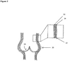
- Figure 2 shows the layered structure of a synthetic root.
- the synthetic root comprises inner (30) and outer (32) nanofiber layers, which may be formed from PCL by jet spraying. In these layers the fibres are circumferentially aligned. Between the nanofibers layers there is a knitted support layer (34), of varying tension. It can be seen that this multi-layered structure defines a substantially tubular shape, with a region of increased diameter (36) corresponding to the sinus regions. In the interior of the tube, leaflets (38) corresponding to cusps project inwardly into the tube. The leaflets (38) are formed from a single nanofiber layer. However, it will be appreciated that in other embodiments the leaflets may further comprise a support layer, such as a knitted support layer.
- the curvature, shape and dimensions of the cusps and sinuses can be varied, which in turn has implications for sinus vortex development as well as helical patterns and the opening and closing of the valves.
- the curvature of the cusps modulates the surface area of the leaflet that faces the inlet flow, which in turn enables the valve to reach its maximum opening potential.
- a high curvature and volume of the sinus bulges, together with a high curvature of the cusps, allows the development of a large vortex between the sinus and the leaflet, which allows the leaflet to close and coapt fully.
- Figures 3A and 3B are images of a knitted support layer (40), while Figures 3C and 3D show their respective schematic diagrams. Figures 3A and 3C show the commissural view which shows two of the sinus bulges. Figures 3B and 3D show an alternative view wherein only a single bulge is visible. It can be seen from these figures that the support has an approximately tubular structure with first (42) and second (44) ends. The first end (42), shown as the upper end in the figures, is constituted by a top sewing ring, while the second end (44) is constituted by a bottom sewing ring.
- each of these portions 46 forms a bulge which corresponds in shape to the sinus of an aortic or pulmonary root.
- Each of the outwardly protruding portions (46) is defined by a curved lower boundary (43), which extends in the direction of the second end (44) of the support.
- a crown-shaped region comprising three triangular portions (54) connected by a base (56) of circular cross-section.
- Each triangular portion (54) extends between two adjacent outwardly protruding portions (46), and corresponds to an interleaflet triangle.
- the bottom sewing ring (44) is located beneath the crown-shaped region.
- Figures 4A and 4B are images of a further support layer (40). It can be seen from these figures that the knitted structure is shaped to resemble the structure of the natural root. Similarly to the support shown in Figure 3 , the support layer is substantially tubular in shape, with first (42) and second (44) ends. Between the ends a region of increased diameter is formed by three outwardly protruding portions (46), which are arranged adjacent to one another around the circumference of the tube. These protruding portions (46) correspond to the sinus regions of the root.
- Each of the outwardly protruding portions (46) is partly defined by a curved edge (47) which extends in the direction of the second end (44) of the root and then curves back in the opposition direction where the edge (47) meets a junction (49), corresponding to the commissure, between adjacent protruding portions (46). Between the curved edges (47) of adjacent outwardly protruding portions (46), an approximately triangular area (54) is formed which corresponds to the interleaflet triangles. The upper boundary (50) of the outwardly protruding portions (46) corresponds to the sinotubular junction.
- an elongate region (48) is provided with a substantially constant diameter. This region corresponds to the ascending artery.
- the support layer of Figure 4 was knitted from a PCL yarn using an industrial knitting machine, which was programmed to follow a prescribed pattern. Different tensions, knit patterns and stitches were used to confer the shape and stiffness of the different regions of the support, which include the ascending artery (48), the sinotubular junction (50), the sinus region (52), the interleaflet triangles (54), and the annulus (56).
- the knit pattern used is a jersey knit with tuck stitches strategically placed to follow the contours of the annulus (56). Each patterned area conveys a different region of different tension.
- a synthetic aortic root is prepared using the following method:
- a knitted support for a synthetic aortic or pulmonary root can be prepared using the following protocol: A commercial Stoll CMS 16gg dubied, flat double bed knitting machine is used with 220dtex PCL yarn.
- the pattern is designed using software M1plus.
- M1plus® pattern software from Stoll is the most effective solution for producing patterns for a highly-optimized knitting process.
- the programme suggests a knitting order for the knitting and transfer rows and these can be changed in the arrangement editor. A number of needles and rows are selected.
- the pattern is created in the design mode. Specific stitch types are chosen and allocated positions in selected areas.
- a 1 & 1 set-up seed-tuck-gore is used for starting and ending the knit.
- the sewing ring has a specified tension.
- the sinus regions have more allocated rows and a different tension, while above the sinotubular region, the tension is again changed.
- Tuck stitches are inserted in specific regions.
- the ply is varied for certain models.
- a module arrangement is generated which is saved as a pattern module and sent for knitting.
Landscapes
- Health & Medical Sciences (AREA)
- Engineering & Computer Science (AREA)
- Life Sciences & Earth Sciences (AREA)
- Animal Behavior & Ethology (AREA)
- Oral & Maxillofacial Surgery (AREA)
- Transplantation (AREA)
- Veterinary Medicine (AREA)
- Public Health (AREA)
- General Health & Medical Sciences (AREA)
- Biomedical Technology (AREA)
- Cardiology (AREA)
- Vascular Medicine (AREA)
- Heart & Thoracic Surgery (AREA)
- Chemical & Material Sciences (AREA)
- Dermatology (AREA)
- Medicinal Chemistry (AREA)
- Epidemiology (AREA)
- Gastroenterology & Hepatology (AREA)
- Pulmonology (AREA)
- Manufacturing & Machinery (AREA)
- Prostheses (AREA)
Claims (14)
- Synthetische Aortenwurzel umfassend mindestens zwei Regionen, wobei in mindestens einer Region die synthetische Wurzel eine mehrschichtige Struktur aufweist umfassend eine Stützschicht, die aus einem gestrickten, gewobenen oder geflochtenen oder 3 D-gedruckten Material oder einer Kombination davon gebildet ist; wobei die Stützschicht zwischen einer inneren und einer äußeren Nanofaserschicht angeordnet ist; und wobei die Stützschicht mindestens eine erste Stützschichtregion und eine zweite Stützschichtregion umfasst, wobei das Muster, das Material, die Dichte und/oder die Spannung der Stützschicht in der ersten Stützschichtregion von denjenigen in der zweiten Stützschichtregion verschieden sind.
- Synthetische Wurzel nach Anspruch 1, wobei die Stützschicht gestrickt ist.
- Synthetische Wurzel nach einem der Ansprüche 1 oder 2, wobei die Steifigkeit der ersten Stützschichtregion von der Steifigkeit der zweiten Stützschichtregion verschieden ist.
- Synthetische Wurzel nach einem der Ansprüche 1 bis 3, wobei die Stützschicht aus einem Garn gebildet ist.
- Synthetische Wurzel nach Anspruch 4, wobei das Garn aus einem Polymer gebildet ist ausgewählt aus PCL, Polyester, PLA, PLGA, Seide, (Poly(dioxanon), Poly(orthoestern), Poly(amidestern), Poly(anhydriden), Polyvinylestern, (Poly)tetrafluorethylen), Poly(ethylen), Poly(ethylenglykol), Polypropylenoxid oder Kombinationen davon.
- Synthetische Wurzel nach einem der vorhergehenden Ansprüche, wobei die Stützschicht eine im Wesentlichen röhrenförmige Gestalt mit einem ersten und zweiten Ende aufweist, wobei eine Region von vergrößertem Durchmesser sich zwischen dem ersten und dem zweiten Ende befindet.
- Synthetische Wurzel nach Anspruch 6, wobei die Region von vergrößertem Durchmesser durch drei nach außen vorspringende Teile gebildet ist, die um den Umfang der Röhre angeordnet sind.
- Synthetische Wurzel nach Anspruch 7, ferner eine kronenförmige Region zwischen der Region von vergrößertem Durchmesser und einem der Enden umfasst, wobei die kronenförmige Region drei rechteckige Teile umfasst, die durch ein Grundteil von kreisförmigem Querschnitt verbunden sind, wobei jeder dreieckige Teil sich zwischen nebeneinanderliegenden nach außen vorspringenden Teilen erstreckt, wobei wahlweise die Steifigkeit der nach außen vorspringenden Teile von der Steifigkeit der kronenförmigen Region verschieden ist.
- Synthetische Wurzel nach einem der vorhergehenden Ansprüche, wobei die innere und/oder äußere Nanofaserschicht ein Polymer umfasst, ausgewählt aus Polycaprolacton (PCL), Polyester, Poly(dioxanon), Poly(orthoestern), Poly(amidestern), Poly(anhydriden), Polyvinylestern, (Poly)tetrafluorethylen), Poly(ethylen), Poly(ethylenglykol), Polypropylenoxid, Polymilchsäure (PLA), Poly(milch-co-glykolsäure (PLGA), Seide oder Kombinationen davon.
- Synthetische Wurzel nach einem der vorhergehenden Ansprüche, wobei die Nanofasern der inneren und/oder Nanofaserschicht aufeinander ausgerichtet sind.
- Synthetische Wurzel nach einem der vorhergehenden Ansprüche, wobei die innere und/oder äußere Nanofaserschicht mit bioaktiven Molekülen dekoriert sind.
- Synthetische Wurzel nach Anspruch 8, wobei die dreieckigen Teile ein Hydrogel umfassen.
- Verfahren zum Herstellen einer synthetischen Wurzel nach einem der vorhergehenden Ansprüche, umfassend die Schritte des:- Bildens einer ersten Nanofaserschicht auf einer Form;- Positionierens einer Stützschicht auf die erste Nanofaserschicht;- Bildens einer zweiten Nanofaserschicht auf der Stützschicht; und- Entfernens der Form;- wobei die Stützschicht aus einem gestrickten, gewobenen, geflochtenen oder 3D-gedruckten Material oder einer Kombination davon gebildet ist; und wobei die Stützschicht mindestens eine erste Stützschichtregion und eine zweite Stützschichtregion umfasst, wobei das Muster, Material, die Dichte und/oder Spannung der Stützschicht in der ersten Stützschichtregion von denjenigen in der zweiten Stützschichtregion verschieden sind.
- Verfahren nach Anspruch 13, wobei die Form aus einem löslichen Material gebildet ist.
Applications Claiming Priority (1)
| Application Number | Priority Date | Filing Date | Title |
|---|---|---|---|
| GBGB1806097.0A GB201806097D0 (en) | 2018-04-13 | 2018-04-13 | Vascular graft |
Publications (2)
| Publication Number | Publication Date |
|---|---|
| EP3552577A1 EP3552577A1 (de) | 2019-10-16 |
| EP3552577B1 true EP3552577B1 (de) | 2021-10-06 |
Family
ID=62203524
Family Applications (1)
| Application Number | Title | Priority Date | Filing Date |
|---|---|---|---|
| EP19169078.3A Active EP3552577B1 (de) | 2018-04-13 | 2019-04-12 | Synthetische wurzel |
Country Status (3)
| Country | Link |
|---|---|
| US (2) | US11291541B2 (de) |
| EP (1) | EP3552577B1 (de) |
| GB (1) | GB201806097D0 (de) |
Families Citing this family (4)
| Publication number | Priority date | Publication date | Assignee | Title |
|---|---|---|---|---|
| US11872123B2 (en) * | 2020-12-10 | 2024-01-16 | GrOwnValve GmbH | Method for manufacturing a cardiac valve prosthesis |
| CN113768662B (zh) * | 2021-08-31 | 2022-11-01 | 东华大学 | 基于机织大提花技术的人工心脏瓣膜用单件织物及其制备和应用 |
| WO2025179040A1 (en) * | 2024-02-21 | 2025-08-28 | Edwards Lifesciences Corporation | Prosthetic heart valve leaflet |
| CN119970299B (zh) * | 2025-01-20 | 2026-02-13 | 江苏百优达生命科技有限公司 | 一种一体式带窦人工血管 |
Family Cites Families (16)
| Publication number | Priority date | Publication date | Assignee | Title |
|---|---|---|---|---|
| US5769884A (en) * | 1996-06-27 | 1998-06-23 | Cordis Corporation | Controlled porosity endovascular implant |
| US6319264B1 (en) * | 1998-04-03 | 2001-11-20 | Bionx Implants Oy | Hernia mesh |
| US6352554B2 (en) * | 1998-05-08 | 2002-03-05 | Sulzer Vascutek Limited | Prosthetic tubular aortic conduit and method for manufacturing the same |
| US6814754B2 (en) | 2000-10-30 | 2004-11-09 | Secant Medical, Llc | Woven tubular graft with regions of varying flexibility |
| US20050070992A1 (en) | 2001-11-28 | 2005-03-31 | Aptus Endosystems, Inc. | Prosthesis systems and methods sized and configured for the receipt and retention of fasteners |
| JP4368163B2 (ja) | 2003-08-19 | 2009-11-18 | 富士フイルム株式会社 | 分光素子アレイ及びこれを備えた分光画像測定装置並びに分光画像測定方法 |
| US20070038290A1 (en) * | 2005-08-15 | 2007-02-15 | Bin Huang | Fiber reinforced composite stents |
| DE102006062360A1 (de) | 2006-12-22 | 2008-06-26 | Aesculap Ag & Co. Kg | Gewebte Aortensinusprothese mit Bulbus |
| US8388679B2 (en) | 2007-01-19 | 2013-03-05 | Maquet Cardiovascular Llc | Single continuous piece prosthetic tubular aortic conduit and method for manufacturing the same |
| US20090299469A1 (en) | 2008-05-27 | 2009-12-03 | The Board Of Regents Of The University Of Texas System | Cone-shaped aortic root replacement graft and methods for making and using same |
| US8353943B2 (en) | 2008-08-29 | 2013-01-15 | Cook Medical Technologies Llc | Variable weave graft with metal strand reinforcement for in situ fenestration |
| US8932344B2 (en) * | 2010-04-29 | 2015-01-13 | Coroneo, Inc. | Aortic conduit configured with terminal ends having neosinuses of valsalva |
| WO2011153340A2 (en) * | 2010-06-02 | 2011-12-08 | The Regents Of The University Of Michigan | Scaffolds and methods of forming the same |
| US20140207248A1 (en) | 2013-01-18 | 2014-07-24 | The Trustees Of The Stevens Institute Of Technology | Hierarchical multiscale fibrous scaffold via 3-d electrostatic deposition prototyping and conventional electrospinning |
| EP3096713B1 (de) * | 2014-01-23 | 2022-09-21 | President and Fellows of Harvard College | Manipulierte polymere ventile, rohrförmige strukturen und folien |
| US10195022B2 (en) * | 2015-04-30 | 2019-02-05 | Mayo Foundation For Medical Education And Research | Nanofibrous biologic heart valve leaflets and fibrosa layer of a leaflet |
-
2018
- 2018-04-13 GB GBGB1806097.0A patent/GB201806097D0/en not_active Ceased
-
2019
- 2019-04-12 EP EP19169078.3A patent/EP3552577B1/de active Active
- 2019-04-12 US US16/383,366 patent/US11291541B2/en active Active
-
2022
- 2022-02-28 US US17/683,031 patent/US20220233306A1/en active Pending
Non-Patent Citations (1)
| Title |
|---|
| None * |
Also Published As
| Publication number | Publication date |
|---|---|
| US20220233306A1 (en) | 2022-07-28 |
| GB201806097D0 (en) | 2018-05-30 |
| US20190314152A1 (en) | 2019-10-17 |
| US11291541B2 (en) | 2022-04-05 |
| EP3552577A1 (de) | 2019-10-16 |
Similar Documents
| Publication | Publication Date | Title |
|---|---|---|
| US20220233306A1 (en) | Expandable aortic or pulmonary root | |
| US11266498B2 (en) | Method of making a prosthetic valve and valve obtained therewith | |
| Ayaz et al. | Textile-templated electrospun anisotropic scaffolds for regenerative cardiac tissue engineering | |
| US7331993B2 (en) | Involuted endovascular valve and method of construction | |
| Doersam et al. | A review: textile technologies for single and multi‐layer tubular soft tissue engineering | |
| JP4467310B2 (ja) | 大動脈弁または僧帽弁の人工心臓弁を製造するための方法、およびその結果得られる大動脈弁または僧帽弁の人工心臓弁 | |
| Wang et al. | Applications of knitted mesh fabrication techniques to scaffolds for tissue engineering and regenerative medicine | |
| DE60022075T2 (de) | Mechanische herzklappe und ihr herstellungsverfahren | |
| CN106572906B (zh) | 制造人工瓣膜的方法和利用所述方法得到的瓣膜 | |
| CN106456326B (zh) | 人工瓣膜和制造人工瓣膜的方法 | |
| JP2005527283A5 (de) | ||
| CN113768662B (zh) | 基于机织大提花技术的人工心脏瓣膜用单件织物及其制备和应用 | |
| CN113768663B (zh) | 一种局部增强的纺织基人工心脏瓣膜用瓣叶及其应用 | |
| Namdari et al. | Nanofibrous bioengineered heart valve—Application in paediatric medicine | |
| CN108014371A (zh) | 一种可再生心脏瓣膜及其制备装置、方法 | |
| Fernández-Colino et al. | Textile-reinforced scaffolds for vascular tissue engineering | |
| Amri et al. | Fibrous composite material for textile heart valve design: in vitro assessment | |
| CN209108208U (zh) | 一种可再生心脏瓣膜及其制备装置和心脏瓣膜假体 | |
| CN119711018A (zh) | 一种带瓣人工血管的制备方法 | |
| JP2022529472A (ja) | 自然に設計された僧帽弁プロテーゼ | |
| Namdari et al. | Paediatric nanofibrous bioprosthetic heart valve | |
| CN110090094B (zh) | 人工瓣膜和制造人工瓣膜的方法 | |
| Sen et al. | Nanofibrous Textile Scaffolds: A New Innovation in Nanotechnology for Tissue Engineering | |
| Simonet et al. | Heart valve tissue regeneration | |
| Sen et al. | 13 Nanofibrous Textile |
Legal Events
| Date | Code | Title | Description |
|---|---|---|---|
| PUAI | Public reference made under article 153(3) epc to a published international application that has entered the european phase |
Free format text: ORIGINAL CODE: 0009012 |
|
| STAA | Information on the status of an ep patent application or granted ep patent |
Free format text: STATUS: THE APPLICATION HAS BEEN PUBLISHED |
|
| AK | Designated contracting states |
Kind code of ref document: A1 Designated state(s): AL AT BE BG CH CY CZ DE DK EE ES FI FR GB GR HR HU IE IS IT LI LT LU LV MC MK MT NL NO PL PT RO RS SE SI SK SM TR |
|
| AX | Request for extension of the european patent |
Extension state: BA ME |
|
| STAA | Information on the status of an ep patent application or granted ep patent |
Free format text: STATUS: REQUEST FOR EXAMINATION WAS MADE |
|
| 17P | Request for examination filed |
Effective date: 20200121 |
|
| RBV | Designated contracting states (corrected) |
Designated state(s): AL AT BE BG CH CY CZ DE DK EE ES FI FR GB GR HR HU IE IS IT LI LT LU LV MC MK MT NL NO PL PT RO RS SE SI SK SM TR |
|
| STAA | Information on the status of an ep patent application or granted ep patent |
Free format text: STATUS: EXAMINATION IS IN PROGRESS |
|
| 17Q | First examination report despatched |
Effective date: 20200904 |
|
| GRAP | Despatch of communication of intention to grant a patent |
Free format text: ORIGINAL CODE: EPIDOSNIGR1 |
|
| STAA | Information on the status of an ep patent application or granted ep patent |
Free format text: STATUS: GRANT OF PATENT IS INTENDED |
|
| INTG | Intention to grant announced |
Effective date: 20210414 |
|
| GRAS | Grant fee paid |
Free format text: ORIGINAL CODE: EPIDOSNIGR3 |
|
| GRAA | (expected) grant |
Free format text: ORIGINAL CODE: 0009210 |
|
| STAA | Information on the status of an ep patent application or granted ep patent |
Free format text: STATUS: THE PATENT HAS BEEN GRANTED |
|
| AK | Designated contracting states |
Kind code of ref document: B1 Designated state(s): AL AT BE BG CH CY CZ DE DK EE ES FI FR GB GR HR HU IE IS IT LI LT LU LV MC MK MT NL NO PL PT RO RS SE SI SK SM TR |
|
| REG | Reference to a national code |
Ref country code: GB Ref legal event code: FG4D |
|
| REG | Reference to a national code |
Ref country code: CH Ref legal event code: EP Ref country code: AT Ref legal event code: REF Ref document number: 1435575 Country of ref document: AT Kind code of ref document: T Effective date: 20211015 |
|
| REG | Reference to a national code |
Ref country code: IE Ref legal event code: FG4D |
|
| REG | Reference to a national code |
Ref country code: DE Ref legal event code: R096 Ref document number: 602019008084 Country of ref document: DE |
|
| REG | Reference to a national code |
Ref country code: LT Ref legal event code: MG9D |
|
| REG | Reference to a national code |
Ref country code: NL Ref legal event code: MP Effective date: 20211006 |
|
| REG | Reference to a national code |
Ref country code: AT Ref legal event code: MK05 Ref document number: 1435575 Country of ref document: AT Kind code of ref document: T Effective date: 20211006 |
|
| PG25 | Lapsed in a contracting state [announced via postgrant information from national office to epo] |
Ref country code: RS Free format text: LAPSE BECAUSE OF FAILURE TO SUBMIT A TRANSLATION OF THE DESCRIPTION OR TO PAY THE FEE WITHIN THE PRESCRIBED TIME-LIMIT Effective date: 20211006 Ref country code: LT Free format text: LAPSE BECAUSE OF FAILURE TO SUBMIT A TRANSLATION OF THE DESCRIPTION OR TO PAY THE FEE WITHIN THE PRESCRIBED TIME-LIMIT Effective date: 20211006 Ref country code: FI Free format text: LAPSE BECAUSE OF FAILURE TO SUBMIT A TRANSLATION OF THE DESCRIPTION OR TO PAY THE FEE WITHIN THE PRESCRIBED TIME-LIMIT Effective date: 20211006 Ref country code: BG Free format text: LAPSE BECAUSE OF FAILURE TO SUBMIT A TRANSLATION OF THE DESCRIPTION OR TO PAY THE FEE WITHIN THE PRESCRIBED TIME-LIMIT Effective date: 20220106 Ref country code: AT Free format text: LAPSE BECAUSE OF FAILURE TO SUBMIT A TRANSLATION OF THE DESCRIPTION OR TO PAY THE FEE WITHIN THE PRESCRIBED TIME-LIMIT Effective date: 20211006 |
|
| PG25 | Lapsed in a contracting state [announced via postgrant information from national office to epo] |
Ref country code: IS Free format text: LAPSE BECAUSE OF FAILURE TO SUBMIT A TRANSLATION OF THE DESCRIPTION OR TO PAY THE FEE WITHIN THE PRESCRIBED TIME-LIMIT Effective date: 20220206 Ref country code: SE Free format text: LAPSE BECAUSE OF FAILURE TO SUBMIT A TRANSLATION OF THE DESCRIPTION OR TO PAY THE FEE WITHIN THE PRESCRIBED TIME-LIMIT Effective date: 20211006 Ref country code: PT Free format text: LAPSE BECAUSE OF FAILURE TO SUBMIT A TRANSLATION OF THE DESCRIPTION OR TO PAY THE FEE WITHIN THE PRESCRIBED TIME-LIMIT Effective date: 20220207 Ref country code: PL Free format text: LAPSE BECAUSE OF FAILURE TO SUBMIT A TRANSLATION OF THE DESCRIPTION OR TO PAY THE FEE WITHIN THE PRESCRIBED TIME-LIMIT Effective date: 20211006 Ref country code: NO Free format text: LAPSE BECAUSE OF FAILURE TO SUBMIT A TRANSLATION OF THE DESCRIPTION OR TO PAY THE FEE WITHIN THE PRESCRIBED TIME-LIMIT Effective date: 20220106 Ref country code: NL Free format text: LAPSE BECAUSE OF FAILURE TO SUBMIT A TRANSLATION OF THE DESCRIPTION OR TO PAY THE FEE WITHIN THE PRESCRIBED TIME-LIMIT Effective date: 20211006 Ref country code: LV Free format text: LAPSE BECAUSE OF FAILURE TO SUBMIT A TRANSLATION OF THE DESCRIPTION OR TO PAY THE FEE WITHIN THE PRESCRIBED TIME-LIMIT Effective date: 20211006 Ref country code: HR Free format text: LAPSE BECAUSE OF FAILURE TO SUBMIT A TRANSLATION OF THE DESCRIPTION OR TO PAY THE FEE WITHIN THE PRESCRIBED TIME-LIMIT Effective date: 20211006 Ref country code: GR Free format text: LAPSE BECAUSE OF FAILURE TO SUBMIT A TRANSLATION OF THE DESCRIPTION OR TO PAY THE FEE WITHIN THE PRESCRIBED TIME-LIMIT Effective date: 20220107 Ref country code: ES Free format text: LAPSE BECAUSE OF FAILURE TO SUBMIT A TRANSLATION OF THE DESCRIPTION OR TO PAY THE FEE WITHIN THE PRESCRIBED TIME-LIMIT Effective date: 20211006 |
|
| REG | Reference to a national code |
Ref country code: DE Ref legal event code: R097 Ref document number: 602019008084 Country of ref document: DE |
|
| PG25 | Lapsed in a contracting state [announced via postgrant information from national office to epo] |
Ref country code: SM Free format text: LAPSE BECAUSE OF FAILURE TO SUBMIT A TRANSLATION OF THE DESCRIPTION OR TO PAY THE FEE WITHIN THE PRESCRIBED TIME-LIMIT Effective date: 20211006 Ref country code: SK Free format text: LAPSE BECAUSE OF FAILURE TO SUBMIT A TRANSLATION OF THE DESCRIPTION OR TO PAY THE FEE WITHIN THE PRESCRIBED TIME-LIMIT Effective date: 20211006 Ref country code: RO Free format text: LAPSE BECAUSE OF FAILURE TO SUBMIT A TRANSLATION OF THE DESCRIPTION OR TO PAY THE FEE WITHIN THE PRESCRIBED TIME-LIMIT Effective date: 20211006 Ref country code: EE Free format text: LAPSE BECAUSE OF FAILURE TO SUBMIT A TRANSLATION OF THE DESCRIPTION OR TO PAY THE FEE WITHIN THE PRESCRIBED TIME-LIMIT Effective date: 20211006 Ref country code: DK Free format text: LAPSE BECAUSE OF FAILURE TO SUBMIT A TRANSLATION OF THE DESCRIPTION OR TO PAY THE FEE WITHIN THE PRESCRIBED TIME-LIMIT Effective date: 20211006 Ref country code: CZ Free format text: LAPSE BECAUSE OF FAILURE TO SUBMIT A TRANSLATION OF THE DESCRIPTION OR TO PAY THE FEE WITHIN THE PRESCRIBED TIME-LIMIT Effective date: 20211006 |
|
| PLBE | No opposition filed within time limit |
Free format text: ORIGINAL CODE: 0009261 |
|
| STAA | Information on the status of an ep patent application or granted ep patent |
Free format text: STATUS: NO OPPOSITION FILED WITHIN TIME LIMIT |
|
| 26N | No opposition filed |
Effective date: 20220707 |
|
| PG25 | Lapsed in a contracting state [announced via postgrant information from national office to epo] |
Ref country code: AL Free format text: LAPSE BECAUSE OF FAILURE TO SUBMIT A TRANSLATION OF THE DESCRIPTION OR TO PAY THE FEE WITHIN THE PRESCRIBED TIME-LIMIT Effective date: 20211006 |
|
| PG25 | Lapsed in a contracting state [announced via postgrant information from national office to epo] |
Ref country code: SI Free format text: LAPSE BECAUSE OF FAILURE TO SUBMIT A TRANSLATION OF THE DESCRIPTION OR TO PAY THE FEE WITHIN THE PRESCRIBED TIME-LIMIT Effective date: 20211006 |
|
| REG | Reference to a national code |
Ref country code: CH Ref legal event code: PL |
|
| REG | Reference to a national code |
Ref country code: BE Ref legal event code: MM Effective date: 20220430 |
|
| PG25 | Lapsed in a contracting state [announced via postgrant information from national office to epo] |
Ref country code: MC Free format text: LAPSE BECAUSE OF FAILURE TO SUBMIT A TRANSLATION OF THE DESCRIPTION OR TO PAY THE FEE WITHIN THE PRESCRIBED TIME-LIMIT Effective date: 20211006 Ref country code: LU Free format text: LAPSE BECAUSE OF NON-PAYMENT OF DUE FEES Effective date: 20220412 Ref country code: LI Free format text: LAPSE BECAUSE OF NON-PAYMENT OF DUE FEES Effective date: 20220430 Ref country code: CH Free format text: LAPSE BECAUSE OF NON-PAYMENT OF DUE FEES Effective date: 20220430 |
|
| PG25 | Lapsed in a contracting state [announced via postgrant information from national office to epo] |
Ref country code: BE Free format text: LAPSE BECAUSE OF NON-PAYMENT OF DUE FEES Effective date: 20220430 |
|
| PG25 | Lapsed in a contracting state [announced via postgrant information from national office to epo] |
Ref country code: IE Free format text: LAPSE BECAUSE OF NON-PAYMENT OF DUE FEES Effective date: 20220412 |
|
| PG25 | Lapsed in a contracting state [announced via postgrant information from national office to epo] |
Ref country code: HU Free format text: LAPSE BECAUSE OF FAILURE TO SUBMIT A TRANSLATION OF THE DESCRIPTION OR TO PAY THE FEE WITHIN THE PRESCRIBED TIME-LIMIT; INVALID AB INITIO Effective date: 20190412 |
|
| PG25 | Lapsed in a contracting state [announced via postgrant information from national office to epo] |
Ref country code: MK Free format text: LAPSE BECAUSE OF FAILURE TO SUBMIT A TRANSLATION OF THE DESCRIPTION OR TO PAY THE FEE WITHIN THE PRESCRIBED TIME-LIMIT Effective date: 20211006 Ref country code: CY Free format text: LAPSE BECAUSE OF FAILURE TO SUBMIT A TRANSLATION OF THE DESCRIPTION OR TO PAY THE FEE WITHIN THE PRESCRIBED TIME-LIMIT Effective date: 20211006 |
|
| PG25 | Lapsed in a contracting state [announced via postgrant information from national office to epo] |
Ref country code: TR Free format text: LAPSE BECAUSE OF FAILURE TO SUBMIT A TRANSLATION OF THE DESCRIPTION OR TO PAY THE FEE WITHIN THE PRESCRIBED TIME-LIMIT Effective date: 20211006 |
|
| PG25 | Lapsed in a contracting state [announced via postgrant information from national office to epo] |
Ref country code: MT Free format text: LAPSE BECAUSE OF FAILURE TO SUBMIT A TRANSLATION OF THE DESCRIPTION OR TO PAY THE FEE WITHIN THE PRESCRIBED TIME-LIMIT Effective date: 20211006 |
|
| PGFP | Annual fee paid to national office [announced via postgrant information from national office to epo] |
Ref country code: DE Payment date: 20250218 Year of fee payment: 7 |
|
| PGFP | Annual fee paid to national office [announced via postgrant information from national office to epo] |
Ref country code: GB Payment date: 20260223 Year of fee payment: 8 |
|
| PGFP | Annual fee paid to national office [announced via postgrant information from national office to epo] |
Ref country code: IT Payment date: 20260320 Year of fee payment: 8 |
|
| PGFP | Annual fee paid to national office [announced via postgrant information from national office to epo] |
Ref country code: FR Payment date: 20260209 Year of fee payment: 8 |