EP3552572A1 - Vorrichtung und verfahren zur unterstützung der planung der einführung einer kanüle - Google Patents
Vorrichtung und verfahren zur unterstützung der planung der einführung einer kanüle Download PDFInfo
- Publication number
- EP3552572A1 EP3552572A1 EP18166743.7A EP18166743A EP3552572A1 EP 3552572 A1 EP3552572 A1 EP 3552572A1 EP 18166743 A EP18166743 A EP 18166743A EP 3552572 A1 EP3552572 A1 EP 3552572A1
- Authority
- EP
- European Patent Office
- Prior art keywords
- tradeoff
- multiple criteria
- data
- puncture trajectory
- trajectory
- Prior art date
- Legal status (The legal status is an assumption and is not a legal conclusion. Google has not performed a legal analysis and makes no representation as to the accuracy of the status listed.)
- Withdrawn
Links
Images


Classifications
-
- A—HUMAN NECESSITIES
- A61—MEDICAL OR VETERINARY SCIENCE; HYGIENE
- A61B—DIAGNOSIS; SURGERY; IDENTIFICATION
- A61B34/00—Computer-aided surgery; Manipulators or robots specially adapted for use in surgery
- A61B34/10—Computer-aided planning, simulation or modelling of surgical operations
-
- A—HUMAN NECESSITIES
- A61—MEDICAL OR VETERINARY SCIENCE; HYGIENE
- A61B—DIAGNOSIS; SURGERY; IDENTIFICATION
- A61B17/00—Surgical instruments, devices or methods, e.g. tourniquets
- A61B17/11—Surgical instruments, devices or methods, e.g. tourniquets for performing anastomosis; Buttons for anastomosis
-
- G—PHYSICS
- G16—INFORMATION AND COMMUNICATION TECHNOLOGY [ICT] SPECIALLY ADAPTED FOR SPECIFIC APPLICATION FIELDS
- G16H—HEALTHCARE INFORMATICS, i.e. INFORMATION AND COMMUNICATION TECHNOLOGY [ICT] SPECIALLY ADAPTED FOR THE HANDLING OR PROCESSING OF MEDICAL OR HEALTHCARE DATA
- G16H50/00—ICT specially adapted for medical diagnosis, medical simulation or medical data mining; ICT specially adapted for detecting, monitoring or modelling epidemics or pandemics
- G16H50/50—ICT specially adapted for medical diagnosis, medical simulation or medical data mining; ICT specially adapted for detecting, monitoring or modelling epidemics or pandemics for simulation or modelling of medical disorders
-
- A—HUMAN NECESSITIES
- A61—MEDICAL OR VETERINARY SCIENCE; HYGIENE
- A61B—DIAGNOSIS; SURGERY; IDENTIFICATION
- A61B17/00—Surgical instruments, devices or methods, e.g. tourniquets
- A61B17/11—Surgical instruments, devices or methods, e.g. tourniquets for performing anastomosis; Buttons for anastomosis
- A61B2017/1107—Surgical instruments, devices or methods, e.g. tourniquets for performing anastomosis; Buttons for anastomosis for blood vessels
-
- A—HUMAN NECESSITIES
- A61—MEDICAL OR VETERINARY SCIENCE; HYGIENE
- A61B—DIAGNOSIS; SURGERY; IDENTIFICATION
- A61B17/00—Surgical instruments, devices or methods, e.g. tourniquets
- A61B17/11—Surgical instruments, devices or methods, e.g. tourniquets for performing anastomosis; Buttons for anastomosis
- A61B2017/1139—Side-to-side connections, e.g. shunt or X-connections
-
- A—HUMAN NECESSITIES
- A61—MEDICAL OR VETERINARY SCIENCE; HYGIENE
- A61B—DIAGNOSIS; SURGERY; IDENTIFICATION
- A61B34/00—Computer-aided surgery; Manipulators or robots specially adapted for use in surgery
- A61B34/10—Computer-aided planning, simulation or modelling of surgical operations
- A61B2034/101—Computer-aided simulation of surgical operations
- A61B2034/102—Modelling of surgical devices, implants or prosthesis
- A61B2034/104—Modelling the effect of the tool, e.g. the effect of an implanted prosthesis or for predicting the effect of ablation or burring
-
- A—HUMAN NECESSITIES
- A61—MEDICAL OR VETERINARY SCIENCE; HYGIENE
- A61B—DIAGNOSIS; SURGERY; IDENTIFICATION
- A61B34/00—Computer-aided surgery; Manipulators or robots specially adapted for use in surgery
- A61B34/10—Computer-aided planning, simulation or modelling of surgical operations
- A61B2034/107—Visualisation of planned trajectories or target regions
-
- A—HUMAN NECESSITIES
- A61—MEDICAL OR VETERINARY SCIENCE; HYGIENE
- A61B—DIAGNOSIS; SURGERY; IDENTIFICATION
- A61B90/00—Instruments, implements or accessories specially adapted for surgery or diagnosis and not covered by any of the groups A61B1/00 - A61B50/00, e.g. for luxation treatment or for protecting wound edges
- A61B90/06—Measuring instruments not otherwise provided for
- A61B2090/064—Measuring instruments not otherwise provided for for measuring force, pressure or mechanical tension
- A61B2090/065—Measuring instruments not otherwise provided for for measuring force, pressure or mechanical tension for measuring contact or contact pressure
-
- A—HUMAN NECESSITIES
- A61—MEDICAL OR VETERINARY SCIENCE; HYGIENE
- A61B—DIAGNOSIS; SURGERY; IDENTIFICATION
- A61B8/00—Diagnosis using ultrasonic, sonic or infrasonic waves
- A61B8/48—Diagnostic techniques
- A61B8/483—Diagnostic techniques involving the acquisition of a 3D volume of data
Definitions
- the present invention relates to puncture planning, and more particularly to an apparatus and method for assisting a user to plan a puncture trajectory between, for example, two vessels of a subject.
- Portal hypertension an important consequence of chronic liver disease, results in the development of significant collateral circulation between the portal system and systemic venous drainage.
- Portal venous congestion causes venous blood leaving the stomach and intestines to be diverted along auxiliary routes of lesser resistance in order to drain to systemic circulation.
- the small vessels that comprise a collateral path for porta-caval circulation become engorged and dilated. These vessels are fragile and often hemorrhage into the gastrointestinal tract.
- a Trans-jugular Intra-hepatic Portosystemic Shunt (TIPS) procedure decreases the effective vascular resistance of the liver through the creation of an alternative pathway for portal venous circulation.
- TIPS Trans-jugular Intra-hepatic Portosystemic Shunt
- a shunt is used to establish an artificial channel between the inflow portal vein (PV) and the outflow hepatic vein (HV). It regards as a palliative treatment for portal hypertension which frequently leads to intestinal bleeding, life-threatening esophageal bleeding and the buildup of fluid within the abdomen (i.e. ascites).
- TIPS is typically performed by an interventional radiologist under fluoroscopic guidance. Access to the liver is gained, as the name 'transjugular' suggests, via the internal jugular vein in the neck. Once access to the jugular vein is confirmed, a guidewire and introducer sheath are typically placed to facilitate the shunt's placement. This enables the interventional radiologist (IR) to gain access to the patient's hepatic vein by travelling from the superior vena vava into the inferior vena cava (IVC) and finally the hepatic vein. From the IVC, IR inserts the catheter in a branch of the HV. A special needle is advanced through the liver parenchyma to connect the hepatic vein to the large PV.
- IVC inferior vena cava
- the channel for shunt is next created by inflating an angioplasty balloon within the liver along the tract created by needle.
- the shunt is completed by placing a special mesh tube known as a stent or endograft to maintain the tract between the higher-pressure portal vein and the lower-pressure hepatic vein.
- the shunt allows a decompression of portal hypertension, since PV blood is now diverted into the systemic circulation.
- FIG. 1 schematically illustrates a puncture trajectory (also called a puncture track) in TIPS procedure.
- a puncture trajectory also called a puncture track
- FIG. 1 illustrates 3 HV branches 120-1, 120-2 and 120-3, and 2 PV branches 130-1, 130-2, but in clinical case either of the number of HV branches and the number of PV branches is random and can be any number of branches.
- FIG. 1 illustrates a puncture trajectory 140 which starts from the exit point 141 on the HV branch 120-1, advances through the liver parenchyma 110, and arrives at the entry point 142 on the PV branch 130-1.
- a puncture tract between any point on any PV branch and any point on any HV branch can work as an alternative pathway for portal venous circulation, and thus there are many possible puncture tracts to build the connection between HV and PV.
- the choice of tracts will result in multiple impacts on clinical outcome, and choosing a most desirable puncture trajectory is a quite challenging task for IRs.
- Puncture trajectory is also called puncture track, and both terms are used interchangeably herein.
- the inventors of the present invention have observed that the choice of puncture tracts will result in multiple impacts on clinical outcome, the IRs, when choosing a most desirable puncture tract, normally need to consider multiple clinical metrics which may be mutually interfered, and the IRs may have to make tradeoff among the clinical metrics. Moreover, the inventors have recognized that details of anatomical structures, such as the structures of HV branches and PV branches, of one subject may be different from another subject, the desirable choice for a particular subject by one IR may be different from another IR depending on IRs skills, experience and preference, and the desirable choice may also depends on the physical conditions of a particular subject.
- an apparatus for assisting a user to plan a puncture trajectory within a region-of-interest of a subject.
- the apparatus comprises: a data interface configured to receive anatomical data of the region-of-interest of the subject and to output the at least one candidate puncture trajectory, and a data processor for calculating at least one candidate puncture trajectory on basis of the anatomical data, multiple criteria, and a tradeoff among the multiple criteria.
- the anatomical data of the subject comprises three-dimensional data of the region of interest.
- the data processor is further configured, upon receiving a first user input for adjusting the tradeoff among the multiple criteria, to adjust the tradeoff among the multiple criteria on basis of the first user input, and to calculate the at least one candidate puncture trajectory on basis of the anatomical data, the multiple criteria and the adjusted tradeoff among the multiple criteria.
- the puncture trajectory is between two vessels.
- the multiple criteria can comprise clinical metrics or non-clinical metrics.
- the apparatus can not only automatically provide one or more candidate puncture trajectories which meet the multiple criteria in a better way among all possibilities, but also allows the user to adjust the tradeoff among the multiple criteria as needed so as to be able to, for example, more favor one criterion in one case and more favor another criterion in another case depending on users' choices.
- the proposed apparatus allows the user to tailor the tradeoff and thus tailor the automatic calculation of the candidate puncture trajectories so as to better meet the actual clinical needs, as recognized by the inventors.
- the data processor is further configured to calculate at least one candidate puncture trajectory on basis of the anatomical data, the multiple criteria, and a predetermined tradeoff among the multiple criteria, and the predetermined tradeoff represents an extreme choice of the tradeoff among the multiple criteria.
- the calculation of candidate puncture trajectory by considering multiple criteria and the tradeoff among them belongs to Multiple-criteria decision making (MCDM) problems.
- MCDM Multiple-criteria decision making
- the tradeoff among the multiple criteria is hard to set, because the relationship among the multiple criteria as well as the impact of the tradeoff on the result are normally not straightforward and hard to be predicted.
- the at least one candidate puncture trajectory calculated on basis of some extreme choices of the tradeoff among the multiple criteria represent the corresponding boundary cases for a particular subject, and such boundary cases can help the users tune or adjust the tradeoff for that particular subject.
- the inventors have proposed a very unique strategy, firstly to present the user with the boundary cases of different criteria, and then to allow the users to fine tune the candidate puncture tracts by adjustment of the tradeoff among the different criteria depending on their judgement.
- the proposed apparatus further comprises a user interface configured to receive the first user input and to present the at least one candidate puncture trajectory. Additionally and alternatively, the proposed apparatus can be communicatively connected to a user interface configured to receive the first user input and to present the at least one candidate puncture trajectory, and the data interface of the proposed apparatus is configured to communicate with the user interface.
- the user interface is further configured to present the at least one candidate puncture trajectory along with the associated tradeoff among the multiple criteria.
- the data processor is further configured to generate an image of the region-of-interest overlaid with the at least one candidate puncture trajectory.
- the tradeoff among the multiple criteria is represented by at least one weight, each weight is associated with one of the multiple criteria.
- the multiple criteria can be transformed into a single criterion by multiplying each criterion with the associated weight and summing up the weighted criteria. In this way, it allows the user to adjust the at least weight to tailor the calculation of the candidate puncture trajectories.
- the apparatus can be configured in such a way that some of the criteria are associated with a predetermined, fixed weight whilst others are associated with the at least one weight which can be adjusted by the users.
- the data processor is further configured to store historical data, wherein the historical data comprises the calculated at least one candidate puncture trajectory associated with each first user input received, and the data processor is further configured to retrieve, upon a second user input for selecting one received first user input, the at least one candidate puncture trajectory associated with the selected first user input from the stored historical data. In this way, it allows the user to review the former user inputs on the tradeoff and the associated candidate puncture trajectories.
- the data process is further configured to calculate, for each of at least one of the multiple criteria, an objective value achieved by one of the at least one candidate puncture trajectory, and the data interface is configured to output the calculated objective value(s).
- the objective value(s) can allow the user to quantitatively assess how the at least one candidate puncture trajectory meets the multiple criteria.
- the anatomical data comprises three-dimensional ultrasound data of anatomical structures in the region-of-interest. Additionally and alternatively, the anatomical data can comprise three-dimensional data of other imaging modalities, such as MR, CT, x-ray etc.
- the puncture trajectory is between two vessels, such as a portal vein and a hepatic vein in the region-of-interest of the subject, and the anatomical data comprises anatomical data of the two vessels, such as anatomical data of at least one portal vein branch and at least one hepatic vein branch.
- the puncture can be performed in other areas, such as gastrointestinal tract.
- the predetermined multiple criteria comprises (1) spatial distance of the puncture trajectory D H-P and (2) at least one of the following: (a) spatial distance between bifurcation of main branch of portal vein and the puncture point on the portal vein D P-B , (b) steepness ⁇ x-y of the puncture trajectory with respect to the transverse plane (i.e. the x-y plane) of the subject, and (c) puncture slice distance Z H-P along the longitudinal direction z of the subject.
- the spatial distance of the puncture trajectory is regarded as a significant factor to predict the one-year shunt patency and the risk of HEP occurrence.
- a method of assisting a user to plan a puncture trajectory between within a region-of-interest of a subject comprising: receiving anatomical data of the subject, the anatomical data of the region-of-interest comprising three-dimensional data of the region-of-interest; receiving a first user input for adjusting the tradeoff among multiple criteria; adjusting the tradeoff among the multiple criteria on basis of the first user input; calculating at least one candidate puncture trajectory on basis of the anatomical data, the multiple criteria, and the adjusted tradeoff among the multiple criteria; and outputting the at least one candidate puncture trajectory associated with the adjusted tradeoff.
- the proposed method further comprises: prior to receive the first user input, calculating at least one candidate puncture trajectory on basis of the anatomical data, the multiple criteria, and a predetermined tradeoff among the multiple criteria; and outputting the at least one candidate puncture trajectory associated with the predetermined tradeoff.
- the predetermined tradeoff represents an extreme choice of the tradeoff among the multiple criteria.
- a computer-readable medium comprising executable instructions, which when executed, cause a processor to perform any of the proposed methods.
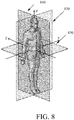
- FIG. 8 illustrates the longitudinal direction, the transverse plane, the coronal plane and the sagittal plane of a subject.
- three principle planes are typically defined in human and animal anatomy:
- the sagittal plane or median plane 810 (longitudinal, anteroposterior) is a plane parallel to the sagittal suture. It divides the body into left and right.
- the coronal plane or frontal plane 820 (vertical) divides the body into dorsal and ventral (back and front, or posterior and anterior) portions.
- the transverse plane or axial plane 830 (lateral, horizontal) divides the body into cranial and caudal (head and tail) portions.
- an x-y-z coordinate system is defined to distinguish the orientation of the planes, namely that y-axis going from front to back, the x-axis going from left to right, and the z-axis going from up to down, as illustrated in FIG. 8 .
- the z-axis is also called the longitudinal direction.
- FIG. schematically 2 illustrates an apparatus 200 for assisting a user to plan a puncture trajectory within a region-of-interest of a subject in accordance with some embodiments of the present invention.
- the apparatus 200 comprises a data interface 211 configured to receive, anatomical data of the region-of-interest of the subject, and to output the at least one candidate puncture trajectory.
- the anatomical data of the subject comprising three-dimensional data of the region-of-interest.
- the region-of-interest comprises the liver or a part of the liver which comprises HV branches and PV branches
- the anatomical data comprises at least three dimensional data of the HV branches and the PV branches.
- the data interface 211 can receive the anatomical data from one or more data sources 230 via any type of communication link.
- the data source 230 can be any image acquisition device such as an ultrasound probe, and/or transient or non-transient storage medium of any other information system or database.
- the apparatus 200 further comprises a data processor 213 communicatively connected to the data interface 211.
- the data interface 211 and the data processor 213 can be an integrated unit or two separated units, and the functions of the data interface 211 and/or the data processor 213 can be provided through the use of dedicated hardware as well as hardware capable of executing software in association with appropriate software.
- the functions can be provided by a single dedicated processor, by a single shared processor, or by a plurality of individual processors, some of which can be shared.
- the data processor 213 is configured to calculate at least one candidate puncture trajectory on basis of the anatomical data, multiple criteria, and a tradeoff among the multiple criteria.
- the calculation of the at least one candidate puncture trajectory by considering multiple criteria and the tradeoff among them belongs to Multiple-criteria decision-making (MCDM) problems. Any existing way or ways developed in future for solving the MCDM problems can be applied to calculate the at least one candidate puncture trajectory.
- Each puncture trajectory can be represented by the coordinates of the puncture trajectory. In some embodiments where the puncture trajectory shall be a straight line, the coordinates of the puncture trajectory comprise the coordinates of the two end points of the trajectory.
- the multiple criteria can be of various types. Some may be defined as minimizing or maximizing certain quantity as a function of the coordinates of the trajectory, some may be defined as an upper and/or lower limit of certain quantity as a function of the coordinates of the trajectory.
- the tradeoff among the multiple criteria basically indicates the priorities or importance of the multiple criteria.
- the tradeoff among the multiple criteria can be represented by at least one weight, each weight is associated with one of the multiple criteria. A larger weight normally indicates a higher priority of the associated criteria.
- the multiple criteria can be combined into a single criterion by weighting, such as by multiplying each criterion with a weight and summing up the weighted criteria.
- the multiple criteria can be mathematically formulated as constrained, weighted cost function. Mathematically, each criterion may be associated with a weight value, but some of the weights can be fixed as predetermined values, and so the tradeoff can be represented by less number of weights then the number of the multiple criteria.
- the data processor 213 is further configured, upon receiving a first user input for adjusting the tradeoff among the multiple criteria, to adjust the tradeoff among the multiple criteria on basis of the first user input, and to calculate the at least one candidate puncture trajectory on basis of the anatomical data, the multiple criteria and the adjusted tradeoff among the multiple criteria.
- the first user input may indicate an adjustment on one or more of the at least one weights.
- the adjustment can be an absolute value or an increment/decrement value.
- the data interface 211 is further configured to receive one or more user inputs comprising the first user input.
- the apparatus 200 further comprises a user interface 250 for receiving the one or more user inputs. Additionally or alternatively, the apparatus 200 can be communicatively connected to a separate user interface 250.
- the user interface 250 can be further configured to present the at least one candidate puncture trajectory.
- the user interface 250 can comprise a display for providing a visual presentation of the at least one candidate puncture trajectory.
- the display can be any device capable of providing visual presentation, such as a monitor, a projector etc.
- the user interface 250 can be a single device or comprises multiple devices.
- the data processor is further configured to calculating at least one candidate puncture trajectory on basis of the anatomical data, the multiple criteria, and a predetermined tradeoff among the multiple criteria, and the predetermined tradeoff represents an extreme choice of the tradeoff among the multiple criteria.
- the adjustable tradeoff are represented by one or more tradeoff parameters (such as weights) and there is a predetermined range for the adjustment of each parameters.
- the extreme choice of the tradeoff refers to a choice where at least one tradeoff parameter is set as the extreme value (e.g. minimal or maximal value) of the predetermined range.
- the data processor 213 can be further configured to store historical data.
- the historical data can comprise a plurality of entries, and each entry comprises a tradeoff and the at least one candidate puncture trajectory calculated using the tradeoff.
- the historical data can comprises each tradeoff used in previous calculations along with the at least one candidate puncture trajectory associated with each tradeoff.
- the used tradeoff can be predetermined tradeoff or can be a tradeoff represented by a first user input previously received.
- the data processor 213 is further configured to retrieve, upon a second user input for selecting a tradeoff previously used, the at least one candidate puncture trajectory associated with the selected tradeoff from the stored historical data.
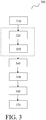
- FIG.3 schematically illustrates a method of assisting a user to plan a puncture trajectory within a region-of-interest of a subject in accordance with some embodiments of the present invention.
- step 310 anatomical data of the subject is received.
- step 340 a first user input is received, and the first user input indicates an adjustment on the tradeoff among multiple criteria.
- step 350 the tradeoff among the multiple criteria is adjusted on basis of the first user input.
- the calculation of at least one candidate puncture trajectory is performed on basis of the anatomical data, the multiple criteria, and the adjusted tradeoff among the multiple criteria.
- the at least one candidate puncture trajectory obtained in step 360 is output to be presented to the user.
- the method further comprises steps 320 and 330.
- step 320 at least one candidate puncture trajectory is calculated on basis of the anatomical data, the multiple criteria, and a predetermined tradeoff among the multiple criteria.
- step 330 the at least one candidate puncture trajectory obtained in step 340 is output to be presented to the user.
- the predetermined tradeoff represents an extreme choice of the tradeoff among the multiple criteria.
- the at least candidate puncture trajectory associated with the predetermined tradeoff represents the boundary cases, and the user may make use of such boundary cases to assist his/her judgement about the adjustment to the tradeoff.
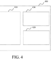
- FIG.4 schematically illustrates an exemplary view 400 presented by a user interface in accordance with some embodiments of the present invention.
- the data interface 211 is configured to output the at least one candidate puncture trajectory.
- the data processor 213 is further configured to generate an image of the region-of-interest overlaid with the at least one candidate puncture trajectory.
- the image of the region-of-interest shall be interpreted in a broad sense.
- the image of the region-of-interest can be the image of some anatomical structures extracted from the region-of-interest.
- the image of can be the image of extracted HV branches and PV branches.
- the view 400 can comprise a region 410 for presenting the image of the region-of-interest overlaid with the at least one candidate puncture trajectory.
- the data processor 213 is further configured to calculate, for each of at least one of the multiple criteria, an objective value achieved by one of the at least one candidate puncture trajectory, and the data interface 211 is configured to output the calculated objective value(s).
- the view 400 can comprise a region 430 for presenting the objective values of one or more of the at least one candidate puncture trajectories.
- the view 400 can comprise a further region 420 for presenting and/or receiving the first user input.
- the further region 420 may comprise one or more slide-like controllable bars, or one or more text input box or any other suitable input means for the user to input preferred the tradeoff.
- the user interface can be configured to receive the first user input in other suitable ways, such as via audio, or via gesture control, etc.
- FIG. 5 schematically illustrates exemplary multiple criteria for planning a puncture trajectory for a TIPS procedure in accordance with some embodiments of the present invention.
- FIG. 5 illustrates a three-dimensional view of a liver region.
- HV 520 and PV 530 are shown to extend into the liver parenchyma 510.
- HV 520 comprises multiple branches.
- PV 530 also comprises multiple branches.
- a puncture trajectory for a TIPS procedure shall start from the exit point on a HV branch, advances through the liver parenchyma, and arrives at the entry point on a PV branch.
- a puncture trajectory 540 illustrated in FIG. 5 starts from the exit point H on a HV branch and ends at the entry point P on a HV branch.
- the x-y-z coordinate system in FIG. 5 is the x-y-z coordinate system defined for a subject as illustrated in FIG. 8 .
- the multiple criteria comprises the following criteria: Spatial distance of the puncture trajectory, denoted as D H-P , which is regarded as a significant factor to predict the one-year shunt patency and the risk of HEP occurrence. The smaller value of D H-P , the lower risk of shunt occlusion and HEP.
- D P-B Spatial distance between bifurcation 550 of main branch of portal vein and the puncture point on the portal vein. It should be bigger than a predetermined threshold, such as 3 cm, to retain enough main branch of portal vein without stent invasion if the patient is to be performed with liver transplantation in the future.
- ⁇ x-y Steepness of the puncture trajectory with respect to the transverse plane (i.e. x-y plane) of the subject, denoted as ⁇ x-y . If the puncture trajectory is perpendicular to x-y plane, in another word, in parallel to z-axis, the steepness ⁇ x-y reaches to maximum. A large steepness value is good to avoid stent distortion, and gain better puncture visualization under DSA (Digital subtraction angiography) which essentially projects three-dimensional image into x-z plane.
- DSA Digital subtraction angiography
- Puncture slice distance along the longitudinal direction z of the subject denoted as Z H-P .
- a puncture with small Z H-P value may be preferred to make extra-hepatic puncture evitable.
- the multiple criteria can be formulated as a constrained, weighted cost function.
- f ( H , P ) is the cost function
- H represents the coordinate of the exit point of the puncture trajectory
- P represents the coordinate of the entry point of the puncture trajectory
- D H-P is the spatial distance of the puncture trajectory
- Z H-P is the puncture slice distance
- ⁇ x-y is the angle with respect to z-axis
- w 1 , w 2 , and w 3 are the weights of the penalty terms of Z H-P and ⁇ x-y , respectively
- D P-B is the distance between the entry point and bifurcation 550 on main branch of portal vein
- T is the value
- FIG.6a illustrates a three-dimensional view of several candidate puncture trajectories 630-1, 630-2 and 630-3 (depicted in solid straight lines) overlaid with the HV branches 610 (depicted in dotted lines) and PV branches 620 (depicted in solid lines) in accordance with an embodiment of the present invention
- FIG.6b illustrates a two-dimensional view obtained by projecting the several candidate punctures trajectories and the HV and PV branches of FIG.6a onto the coronal plane (i.e. x-z plane) of the subject.
- the x-y-z coordinate system in FIGs.6a-6b is the x-y-z coordinate system defined for a subject as illustrated in FIG. 8 .
- FIG.4b sets the view point on x-z plane.
- slices distance of the trajectory 630-1 is relatively big, and pinpoint the puncture direction should be toward to another PV branch.
- This type of puncture recommendation may more delight to some IRs as the puncture direction along spine is easy observed from DSA view. Meanwhile, the risk from stent distortion with this type of puncture tract is able to be decreased.
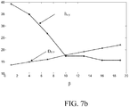
- FIG.7a illustrates a three-dimensional view of several candidate puncture trajectories 730-1 to 730-7 calculated under different values of weight ⁇ associated with the steepness ⁇ x-y , overlaid with the HV branches 710 and PV branches 720 in accordance with an embodiment of the present invention.
- the x-y-z coordinate system in FIG.7a is the x-y-z coordinate system defined for a subject as illustrated in FIG. 8 .
- FIG.7b illustrates the objective values of the two criteria, namely the spatial distance D H-P of the puncture trajectory in unit of millimeter and the steepness ⁇ x-y of the puncture trajectory with respect to the transverse plane (i.e.
- the weight ⁇ is set to be 1, and the weight ⁇ changes from 1 to 19.
- Table 1 spatial distance and the steepness of the puncture trajectory under different ⁇ ⁇ 1 4 7 10 13 16 19 D H-P (mm) 13.62 14.89 15.98 17.74 19.26 20.67 22.03 ⁇ x-y (degree) 39.27 34.91 26.81 17.36 17.36 15.61 15.61
- FIG.6a-6b The three candidate puncture trajectories illustrated in FIG.6a-6b can be regarded as an initialization to a specific entry-point. They are just the boundary cases with extreme conditions. After a rapid judgment from IRs, the IRs can change the penalty weights (a, ⁇ value) of cost function discretely or continuously by means of a slide-liked control bar or other suitable input means. Take P value for instance, FIG.7a presents the sorts of puncture recommendation in the variety of steepness value changes, in three dimensional view. FIG.7b gives the tendency of the objective values of the two criteria D H-P and ⁇ x-y when ⁇ value changes from 1 to 19.
- the technique processes described herein may be implemented by various means. For example, these techniques may be implemented in hardware, software, or a combination thereof.
- the technical processes may be implemented within one or more application specific integrated circuits (ASICs), digital signal processors (DSPs), digital signal processing devices (DSPDs), programmable logic devices (PLDs), field programmable gate arrays (FPGAs), processors, controllers, microcontrollers, microprocessors, other electronic units designed to perform the functions described herein, or a combination thereof.
- ASICs application specific integrated circuits
- DSPs digital signal processors
- DSPDs digital signal processing devices
- PLDs programmable logic devices
- FPGAs field programmable gate arrays
- processors controllers, microcontrollers, microprocessors, other electronic units designed to perform the functions described herein, or a combination thereof.
- implementation can be through modules (e.g., procedures, functions, and so on) that perform the functions described herein.
- the software codes may be stored in a
- aspects of the claimed subject matter may be implemented as a method, apparatus, system, or article of manufacture using standard programming and/or engineering techniques to produce software, firmware, hardware, or any combination thereof to control a computer or computing components to implement various aspects of the claimed subject matter.
- article of manufacture as used herein is intended to encompass a computer program accessible from any computer-readable device, carrier, or media.
- computer readable media can include but are not limited to magnetic storage devices (e.g., hard disk, floppy disk, magnetic strips%), optical disks (e.g., compact disk (CD), digital versatile disk (DVD)...), smart cards, and flash memory devices (e.g., card, stick, key drive).
- magnetic storage devices e.g., hard disk, floppy disk, magnetic strips
- optical disks e.g., compact disk (CD), digital versatile disk (DVD)
- smart cards e.g., card, stick, key drive
- a component may be, but is not limited to, a process running on a processor, a processor, an object, an executable, a thread of execution, a program, and/or a computer.
- a component may be, but is not limited to, a process running on a processor, a processor, an object, an executable, a thread of execution, a program, and/or a computer.
- an application running on a server and the server can be a component.
- One or more components may reside within a process and/or thread of execution and a component may be localized on one computer and/or distributed among two or more computers.
Landscapes
- Health & Medical Sciences (AREA)
- Engineering & Computer Science (AREA)
- Medical Informatics (AREA)
- Public Health (AREA)
- Surgery (AREA)
- Life Sciences & Earth Sciences (AREA)
- General Health & Medical Sciences (AREA)
- Biomedical Technology (AREA)
- Heart & Thoracic Surgery (AREA)
- Molecular Biology (AREA)
- Animal Behavior & Ethology (AREA)
- Nuclear Medicine, Radiotherapy & Molecular Imaging (AREA)
- Veterinary Medicine (AREA)
- Robotics (AREA)
- Data Mining & Analysis (AREA)
- Databases & Information Systems (AREA)
- Pathology (AREA)
- Epidemiology (AREA)
- Primary Health Care (AREA)
- Apparatus For Radiation Diagnosis (AREA)
Priority Applications (6)
| Application Number | Priority Date | Filing Date | Title |
|---|---|---|---|
| EP18166743.7A EP3552572A1 (de) | 2018-04-11 | 2018-04-11 | Vorrichtung und verfahren zur unterstützung der planung der einführung einer kanüle |
| PCT/EP2018/086054 WO2019129606A1 (en) | 2017-12-28 | 2018-12-20 | Apparatus and method for assisting puncture planning |
| US16/958,077 US20200315710A1 (en) | 2017-12-28 | 2018-12-20 | Apparatus and method for assisting puncture planning |
| JP2020535592A JP7278289B2 (ja) | 2017-12-28 | 2018-12-20 | 穿刺計画を支援するための装置及び方法 |
| DE112018006643.6T DE112018006643T5 (de) | 2017-12-28 | 2018-12-20 | Einrichtung und verfahren zur unterstützung einer punktionsplanung |
| CN201880088017.3A CN111655183A (zh) | 2017-12-28 | 2018-12-20 | 用于辅助穿刺规划的装置和方法 |
Applications Claiming Priority (1)
| Application Number | Priority Date | Filing Date | Title |
|---|---|---|---|
| EP18166743.7A EP3552572A1 (de) | 2018-04-11 | 2018-04-11 | Vorrichtung und verfahren zur unterstützung der planung der einführung einer kanüle |
Publications (1)
| Publication Number | Publication Date |
|---|---|
| EP3552572A1 true EP3552572A1 (de) | 2019-10-16 |
Family
ID=62067326
Family Applications (1)
| Application Number | Title | Priority Date | Filing Date |
|---|---|---|---|
| EP18166743.7A Withdrawn EP3552572A1 (de) | 2017-12-28 | 2018-04-11 | Vorrichtung und verfahren zur unterstützung der planung der einführung einer kanüle |
Country Status (1)
| Country | Link |
|---|---|
| EP (1) | EP3552572A1 (de) |
Cited By (2)
| Publication number | Priority date | Publication date | Assignee | Title |
|---|---|---|---|---|
| CN112137721A (zh) * | 2020-06-05 | 2020-12-29 | 哈尔滨工业大学 | 一种基于超声图像的穿刺针针尖与血管壁深度定位方法 |
| CN115844545A (zh) * | 2023-02-27 | 2023-03-28 | 潍坊医学院附属医院 | 一种血管介入智能手术机器人及控制方法 |
Citations (8)
| Publication number | Priority date | Publication date | Assignee | Title |
|---|---|---|---|---|
| WO1999042977A1 (en) * | 1998-02-23 | 1999-08-26 | Algotec Systems Ltd. | Automatic path planning system and method |
| US20090259230A1 (en) * | 2008-04-15 | 2009-10-15 | Medtronic, Inc. | Method And Apparatus For Optimal Trajectory Planning |
| US20100217117A1 (en) * | 2009-02-25 | 2010-08-26 | Neil David Glossop | Method, system and devices for transjugular intrahepatic portosystemic shunt (tips) procedures |
| US20130085344A1 (en) * | 2011-10-04 | 2013-04-04 | Medtronic Navigation, Inc. | Method and Apparatus for Assisted Trajectory Planning |
| WO2014019714A2 (en) * | 2012-07-30 | 2014-02-06 | Brainlab Ag | Method for inverse trajectory planning |
| WO2016083927A1 (en) * | 2014-11-27 | 2016-06-02 | Synaptive Medical (Barbados) Inc. | Method, system and apparatus for displaying surgical engagement paths |
| WO2016181317A2 (en) * | 2015-05-12 | 2016-11-17 | Navix International Limited | Calculation of an ablation plan |
| CN105342701B (zh) * | 2015-12-08 | 2018-02-06 | 中国科学院深圳先进技术研究院 | 一种基于影像信息融合的病灶虚拟穿刺系统 |
-
2018
- 2018-04-11 EP EP18166743.7A patent/EP3552572A1/de not_active Withdrawn
Patent Citations (8)
| Publication number | Priority date | Publication date | Assignee | Title |
|---|---|---|---|---|
| WO1999042977A1 (en) * | 1998-02-23 | 1999-08-26 | Algotec Systems Ltd. | Automatic path planning system and method |
| US20090259230A1 (en) * | 2008-04-15 | 2009-10-15 | Medtronic, Inc. | Method And Apparatus For Optimal Trajectory Planning |
| US20100217117A1 (en) * | 2009-02-25 | 2010-08-26 | Neil David Glossop | Method, system and devices for transjugular intrahepatic portosystemic shunt (tips) procedures |
| US20130085344A1 (en) * | 2011-10-04 | 2013-04-04 | Medtronic Navigation, Inc. | Method and Apparatus for Assisted Trajectory Planning |
| WO2014019714A2 (en) * | 2012-07-30 | 2014-02-06 | Brainlab Ag | Method for inverse trajectory planning |
| WO2016083927A1 (en) * | 2014-11-27 | 2016-06-02 | Synaptive Medical (Barbados) Inc. | Method, system and apparatus for displaying surgical engagement paths |
| WO2016181317A2 (en) * | 2015-05-12 | 2016-11-17 | Navix International Limited | Calculation of an ablation plan |
| CN105342701B (zh) * | 2015-12-08 | 2018-02-06 | 中国科学院深圳先进技术研究院 | 一种基于影像信息融合的病灶虚拟穿刺系统 |
Cited By (3)
| Publication number | Priority date | Publication date | Assignee | Title |
|---|---|---|---|---|
| CN112137721A (zh) * | 2020-06-05 | 2020-12-29 | 哈尔滨工业大学 | 一种基于超声图像的穿刺针针尖与血管壁深度定位方法 |
| CN112137721B (zh) * | 2020-06-05 | 2022-04-01 | 哈尔滨工业大学 | 一种基于超声图像的穿刺针针尖与血管壁深度定位方法 |
| CN115844545A (zh) * | 2023-02-27 | 2023-03-28 | 潍坊医学院附属医院 | 一种血管介入智能手术机器人及控制方法 |
Similar Documents
| Publication | Publication Date | Title |
|---|---|---|
| US20200315710A1 (en) | Apparatus and method for assisting puncture planning | |
| US7650179B2 (en) | Computerized workflow method for stent planning and stenting procedure | |
| JP6272618B2 (ja) | 自動医療画像注釈の検証及び修正のためのシステム、方法及びコンピュータ可読媒体 | |
| CN109741344A (zh) | 血管分割方法、装置、医疗影像设备及存储介质 | |
| US7565000B2 (en) | Method and apparatus for semi-automatic segmentation technique for low-contrast tubular shaped objects | |
| DE102011083522B4 (de) | Verfahren und Vorrichtung zur Visualisierung der Qualität eines Ablationsvorgangs | |
| EP3025638B1 (de) | Verfahren zur bestimmung der endgültigen länge von stents vor der positionierung davon | |
| DE112014000925T5 (de) | Chirurgisches Navigationsplanungssystem und damit verbundene Verfahren | |
| US10639105B2 (en) | Navigation apparatus and method | |
| EP3476294B1 (de) | Bestimmen einer punktionsposition eines gefässes | |
| DE112016006135T5 (de) | Vorrichtung für medizinische Berichte | |
| EP3552572A1 (de) | Vorrichtung und verfahren zur unterstützung der planung der einführung einer kanüle | |
| US20110052028A1 (en) | Method and system of liver segmentation | |
| CA3109234A1 (en) | A virtual tool kit for radiologists | |
| US11417071B1 (en) | Virtual toolkit for radiologists | |
| US10779889B2 (en) | Planning support during an interventional procedure | |
| EP3983995B1 (de) | Analyse angiografischer daten | |
| DE102011075419A1 (de) | Verfahren zum Unterstützen eines optimalen Positionierens einer Verschlussstelle in einem Blutgefäß bei einer Tumor-Embolisation | |
| DE102015220768A1 (de) | Verfahren, Vorrichtung und Computerprogramm zur visuellen Unterstützung eines Behandlers bei der Behandlung eines Zielgebietes eines Patienten | |
| CN113710190A (zh) | 评估导丝移动路径的装置及方法 | |
| DE102020201928A1 (de) | Verfahren zur Deformationskorrektur | |
| DE102005059300A1 (de) | Bildgebungsverfahren und -einrichtung zur Unterstützung eines Chirurgen bei einem interventionellen radiologischen Vorgang | |
| DE102019214560A1 (de) | Verfahren zur automatischen Auswahl von medizinischen Strukturen und Vorrichtung | |
| CL Lim | Antegrade techniques for chronic total occlusions | |
| DE102005056701A1 (de) | Verfahren und Vorrichtung zur Planung einer Behandlung |
Legal Events
| Date | Code | Title | Description |
|---|---|---|---|
| PUAI | Public reference made under article 153(3) epc to a published international application that has entered the european phase |
Free format text: ORIGINAL CODE: 0009012 |
|
| AK | Designated contracting states |
Kind code of ref document: A1 Designated state(s): AL AT BE BG CH CY CZ DE DK EE ES FI FR GB GR HR HU IE IS IT LI LT LU LV MC MK MT NL NO PL PT RO RS SE SI SK SM TR |
|
| AX | Request for extension of the european patent |
Extension state: BA ME |
|
| RAP1 | Party data changed (applicant data changed or rights of an application transferred) |
Owner name: KONINKLIJKE PHILIPS N.V. |
|
| STAA | Information on the status of an ep patent application or granted ep patent |
Free format text: STATUS: THE APPLICATION IS DEEMED TO BE WITHDRAWN |
|
| 18D | Application deemed to be withdrawn |
Effective date: 20200603 |