EP3552301B1 - Procédé de fabrication d'un rotor pour une machine électrique synchrone et un rotor pour une machine électrique synchrone - Google Patents
Procédé de fabrication d'un rotor pour une machine électrique synchrone et un rotor pour une machine électrique synchrone Download PDFInfo
- Publication number
- EP3552301B1 EP3552301B1 EP17828661.3A EP17828661A EP3552301B1 EP 3552301 B1 EP3552301 B1 EP 3552301B1 EP 17828661 A EP17828661 A EP 17828661A EP 3552301 B1 EP3552301 B1 EP 3552301B1
- Authority
- EP
- European Patent Office
- Prior art keywords
- rotor
- laminated core
- flux
- injection
- magnetic particles
- Prior art date
- Legal status (The legal status is an assumption and is not a legal conclusion. Google has not performed a legal analysis and makes no representation as to the accuracy of the status listed.)
- Active
Links
Images


Classifications
-
- H—ELECTRICITY
- H02—GENERATION; CONVERSION OR DISTRIBUTION OF ELECTRIC POWER
- H02K—DYNAMO-ELECTRIC MACHINES
- H02K15/00—Processes or apparatus specially adapted for manufacturing, assembling, maintaining or repairing of dynamo-electric machines
- H02K15/02—Processes or apparatus specially adapted for manufacturing, assembling, maintaining or repairing of dynamo-electric machines of stator or rotor bodies
- H02K15/03—Processes or apparatus specially adapted for manufacturing, assembling, maintaining or repairing of dynamo-electric machines of stator or rotor bodies having permanent magnets
-
- H—ELECTRICITY
- H02—GENERATION; CONVERSION OR DISTRIBUTION OF ELECTRIC POWER
- H02K—DYNAMO-ELECTRIC MACHINES
- H02K1/00—Details of the magnetic circuit
- H02K1/02—Details of the magnetic circuit characterised by the magnetic material
-
- H—ELECTRICITY
- H02—GENERATION; CONVERSION OR DISTRIBUTION OF ELECTRIC POWER
- H02K—DYNAMO-ELECTRIC MACHINES
- H02K1/00—Details of the magnetic circuit
- H02K1/06—Details of the magnetic circuit characterised by the shape, form or construction
- H02K1/22—Rotating parts of the magnetic circuit
- H02K1/27—Rotor cores with permanent magnets
- H02K1/2706—Inner rotors
- H02K1/272—Inner rotors the magnetisation axis of the magnets being perpendicular to the rotor axis
- H02K1/274—Inner rotors the magnetisation axis of the magnets being perpendicular to the rotor axis the rotor consisting of two or more circumferentially positioned magnets
- H02K1/2753—Inner rotors the magnetisation axis of the magnets being perpendicular to the rotor axis the rotor consisting of two or more circumferentially positioned magnets the rotor consisting of magnets or groups of magnets arranged with alternating polarity
- H02K1/276—Magnets embedded in the magnetic core, e.g. interior permanent magnets [IPM]
- H02K1/2766—Magnets embedded in the magnetic core, e.g. interior permanent magnets [IPM] having a flux concentration effect
-
- H—ELECTRICITY
- H02—GENERATION; CONVERSION OR DISTRIBUTION OF ELECTRIC POWER
- H02K—DYNAMO-ELECTRIC MACHINES
- H02K21/00—Synchronous motors having permanent magnets; Synchronous generators having permanent magnets
- H02K21/12—Synchronous motors having permanent magnets; Synchronous generators having permanent magnets with stationary armatures and rotating magnets
- H02K21/14—Synchronous motors having permanent magnets; Synchronous generators having permanent magnets with stationary armatures and rotating magnets with magnets rotating within the armatures
Definitions
- the invention relates to a method for producing a rotor for a synchronous reluctance machine.
- a rotor for a synchronous reluctance machine is usually made from a soft magnetic material by stacking individual electromagnetic sheets with the appropriate sheet metal cutting geometry on top of each other in the axial direction.
- the soft magnetic element comprises flux-conducting and flux-blocking sections that differ from one another in terms of their magnetic permeability.
- the section with high magnetic conductivity is designated as the d-axis, and the section with comparatively low conductivity is designated as the q-axis of the rotor.
- Flux barriers are created by making material cutouts in the individual sheet metal sections of the rotor package. In particular, several cutouts are provided in the q-direction per pole, which reduces the magnetic conductivity and inhibits the magnetic flux in the q-direction.
- the flux barriers are usually filled with air.
- An efficient sheet metal cutting geometry is, for example, US$5,818,140 known, to which reference is made in full at this point.
- the introduction of sintered magnets is known in this context.
- the EN 10 2014 2111113 A1 discloses a rotor or stator for an electrical machine, in particular an electrically commutated electric motor, with a permanent magnet.
- the permanent magnet is overmolded with a plastic material.
- the EN 10 2007 060011 A1 shows a secondary part of a permanent magnet electrical machine and a method for its production.
- the rotor of the EN 10 2011 089 488 A1 has magnets fixed by thermoplastic material.
- the JP 2001 238418 A discloses a reluctance motor for a high-speed machine or a large rotating machine.
- a rotor package made up of a large number of sheet metal sections in the axial direction. Individual sheet metal sections are provided with recesses to form flux barriers.
- a magnetic particle or plastic material containing magnetic particles is injected into at least some of the flux barriers of the rotor package. The injection allows for simple and uncomplicated insertion of the magnets.
- this process step does not require any special sheet metal cutting geometry or special design of the flux barriers. Rather, the process can be used for any conceivable sheet metal cutting geometry of a rotor for a synchronous reluctance machine.
- the hardening plastic material ensures that the magnets or magnetic particles are sufficiently fixed in the flux barriers.
- the magnetic particles are permanent magnetic particles.
- the magnetic particles contained in the plastic material must first be aligned by applying a defined magnetic field. According to the invention, this achieves the desired arrangement of the individual magnetic particles, so that the flow blocking effect in the q direction is increased.
- the alignment of the magnetic components of the plastic material is best carried out when the plastic material is in a liquid or solidifying state.
- all flux barriers of the rotor are injected, or alternatively only some of the flux barriers per salient rotor pole. It is also conceivable that certain parts of a flux barrier remain empty or are filled with another material. However, it may also be possible and sensible for at least one flux barrier to be completely filled with the plastic material containing the magnetic particles.
- Possible magnetic particles for the plastic material include ferrite and/or an alloy of neodymium, iron and boron (NdFeB) and/or an alloy of samarium (Sm) with the metal cobalt (Co).
- the injection of the plastic material into the individual flow barriers is best done in an injection molding machine, which picks up the rotor package after the individual sheet metal sections have been stacked.
- the rotor package can, for example, be loosely assembled and passed on to the injection molding machine in this state.
- the sheet metal package can be axially fixed in advance, for example by applying it to the rotor shaft or fixing it using end plates that are attached to the axial end faces of the package.
- the individual flow barriers are filled by injection molding, whereby a plastic material with corresponding magnetic particles is introduced into the flow barriers.
- the sheets can be stacked beforehand using an auxiliary device, for example, and the stacked sheet stack is then introduced into the plastic injection molding machine.
- the sheet stack can be fixed or clamped in the axial direction using end plates after stacking.
- the sheet stack is introduced into the plastic injection molding machine with the end plates. It is of course sensible to attach at least two axial end plates, ie one for each rotor face. In principle, however, the use of a single axial end plate is also conceivable.
- the end plates used are provided with one or more injection channels before or after attachment to the rotor package, which penetrate the end plate in the axial direction of the rotor and thereby form an injection channel from the outside into the flow barrier of the rotor package located behind it.
- At least one injection channel is provided in the end plate for each flow barrier to be filled. It is conceivable, for example, that several injection channels lie on a common axis in the radial direction; ideally, these are offset from one another on the q-axis at the distance of the flow barriers.
- a narrowing of the at least one injection channel in the injection direction also proves to be advantageous.
- a conical shape of at least one injection channel is particularly preferred, in particular the injection channel tapers to a point in the injection direction.
- the narrowing or conical shape allows the laminated core to be braced during the injection process.
- the injected material therefore acts in a similar way to a screw or countersunk screw penetrating the core in the axial direction, which allows better axial fixation of the stacked laminated core. It is conceivable that the laminated core is braced by introducing a material other than the plastic material.
- the end plate can be connected to the rotor core by means of further fastening points, in particular by means of several fastening points arranged distributed around the shaft bore.
- individual flux barriers can also be partially filled with the plastic material containing magnetic particles, which allows special modifications of the rotor.
- partial injection into one or more flux barriers is conceivable, so that ideally at least one the radially outer ends of the flux barrier remain free. Particularly preferably, both radially outer ends of the flux barrier remain empty. If this applies to all or at least a large proportion of the flux barriers, an outer ring region of the rotor is formed, the flux barrier regions located therein are not sprayed with the material containing the magnetic particles.
- the remaining free flux barrier region of the outer ring region is filled with an electrically conductive but non-magnetic material, a starting cage for the rotor can be simulated in this way, since filling the flux barrier regions in the outer ring region with electrically conductive but non-magnetic material forms guide elements running in the axial direction.
- This advantageous design also allows the rotor to be operated as a line-start synchronous reluctance motor.
- the outer area of the flow barriers can be filled either before the plastic material is introduced or alternatively after the plastic material has been introduced.
- the present invention also relates to a rotor for a synchronous reluctance machine, which is stacked from individual sheet metal sections to form a sheet metal package.
- Individual sheet metal sections have one or more recesses for forming flux barriers.
- individual flux barriers of the sheet metal package are filled with a plastic material containing magnetic particles by injection molding. The magnetic particles are aligned in such a way that the permeability in the q direction is reduced compared to unfilled flux barriers.
- the rotor is manufactured according to the method according to the present invention.
- the invention also relates to a synchronous reluctance machine with the rotor according to the invention.
- the advantages and properties of the rotor or the synchronous reluctance machine are therefore apparent from the preceding description of the method according to the invention. For this reason, a repeated description is omitted.
- Fig.1 shows a sheet metal section 10 of the rotor package according to the invention made of an electromagnetic sheet with a known shape of the flux barriers 11.
- the selected rotor geometry provides a total of three banana-shaped flux barriers per salient pole.
- the flux barriers are initially formed by recesses in the electromagnetic sheet metal material.
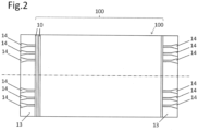
- the rotor package 100 is then formed by axially stacking a large number of sheet metal sections 10. A side view of the package 100 is shown in the Figure 2 refer to.
- the recesses 11 are filled with a plastic material 12 after stacking the package 100 by plastic injection molding in an injection molding machine.
- the plastic material used comprises a large number of magnetic particles, which are consequently injected into the flow barriers 11 together with the plastic.
- the already injected flow barriers are in Figure 1 designated by the reference numeral 11'.
- the magnetic particles contained therein are aligned by applying an external magnetic field in such a way that they reduce the permeability of the rotor in the q direction as much as possible and consequently optimize the relationship between the d and q axes.
- Fig.2 shows a side view of the rotor package 100 according to the invention, wherein additional end plates 13 are provided on the end faces of the laminated core 100 for axially fixing the laminated core 100.
- the end plates 13 have individual injection channels 14 which penetrate the end plates 13 in the axial direction and consequently form an inlet channel into the flow barriers 11 of the rotor package 100 located behind them.
- the injection channels are conical in shape, with a wide funnel opening 15 accessible from the outside.
- the narrow opening 16 opens into the flow barrier 11 located directly behind it (see Figure 3).
- Fig. 3 shows a top view of the end plate 13, with the lamination stack 100 behind it or the directly adjacent lamination section 10 being indicated in dashed lines.
- the three injection channels 14 per rotor pole can be seen here, which are offset from one another on an axis in the radial direction. In the embodiment of the Fig.3
- the injection channels 14 are offset from one another on the q-axis of each rotor pole.
- the plastic material can be injected into the sheet metal cutting geometry behind them through these injection channels 14.
- the conical design also allows the sheet metal package 100 to be braced.
- These individual injection channels 14 can also form additional holding points for fixing the end plate 13 to the rotor package. Additional holding points 17 can be provided distributed around the shaft bore 18.
- the flux barriers 11 could each be only partially filled with the plastic material 12, so that the radially outer end areas remain empty for each flux barrier 11.
- the outer ring area remains empty or is additionally filled with die-cast aluminum. Due to the electrical conductivity of the aluminum, a starting cage can be simulated in the outer ring area, so that such a rotor can be operated as a line-start synchronous reluctance motor.
- the outer area can also be filled before the magnetic plastic material is injected.
Landscapes
- Engineering & Computer Science (AREA)
- Power Engineering (AREA)
- Manufacturing & Machinery (AREA)
- Permanent Field Magnets Of Synchronous Machinery (AREA)
- Manufacture Of Motors, Generators (AREA)
- Iron Core Of Rotating Electric Machines (AREA)
Claims (11)
- Procédé de fabrication d'un rotor destiné à une machine à réluctance synchrone, ledit procédé comprenant les étapes suivantes :a. empiler un noyau de rotor (100) sous la forme d'un noyau feuilleté en tôle (100) formé d'un grand nombre de flans de tôle (10) qui comprennent des portions de guidage de flux appelées axe d et des portions de blocage de flux appelées axe q, les flans de tôle (10) étant chacun conçus avec des évidements dans la direction de l'axe q destinés à former des barrières anti-flux (11) du noyau feuilleté en tôle (100),b. remplir les barrières anti-flux individuelles (11) du noyau feuilleté en tôle (100) avec une matière synthétique (12) contenant des particules magnétiques permanentes par moulage par injection,c. orienter les particules magnétiques permanentes contenues par application d'un champ magnétique extérieur de sorte que la perméabilité magnétique dans la direction q du rotor soit réduite par rapport aux barrières anti-flux non remplies (11) du noyau feuilleté en tôle (100).
- Procédé selon la revendication 1, caractérisé en ce que la matière synthétique (12) contient comme particules magnétiques permanentes de la ferrite et/ou un alliage de néodyme, de fer et de bore (NdFeB) et/ou un alliage de samarium (Sm) avec le métal cobalt (Co).
- Procédé selon l'une des revendications précédentes, caractérisé en ce que le noyau feuilleté en tôle (100) est pourvu d'un ou plusieurs disques d'extrémité axiaux (13), dans lesquels est ménagé au moins un conduit d'injection (14) s'étendant axialement afin d'injecter la matière synthétique (12) à travers la plaque d'extrémité (13) jusque dans au moins une des barrières anti-flux (11) du noyau feuilleté en tôle (100) qui est située derrière ladite plaque d'extrémité.
- Procédé selon la revendication 3, caractérisé en ce que l'au moins un conduit d'injection (14) se rétrécit dans la direction d'injection afin d'obtenir un renforcement du noyau feuilleté en tôle (100) par l'injection, de manière particulièrement préférée l'au moins un conduit d'injection (14) est conique et s'étend en pointe dans la direction d'injection.
- Procédé selon la revendication 4, caractérisé en ce qu'une matière différente de la matière synthétique (12) est utilisée pour renforcer le noyau feuilleté en tôle (100).
- Procédé selon l'une des revendications précédentes 4 à 6, caractérisé en ce que plusieurs conduits d'injection (14), de préférence par pôle de rotor, sont ménagés dans l'au moins une plaque d'extrémité (13) en étant situés sur un axe dans la direction radiale du rotor.
- Procédé selon l'une des revendications précédentes 4 à 7, caractérisé en ce qu'au moins un conduit d'injection (14) forme un point de fixation de la plaque d'extrémité (13) sur le noyau feuilleté en tôle (100), des points de retenue supplémentaires étant éventuellement prévus.
- Procédé selon l'une des revendications précédentes, caractérisé en ce qu'au moins une des barrières anti-flux (11) du noyau feuilleté en tôle (100) est remplie avec la matière synthétique (12) qui contient des particules magnétiques permanentes, en particulier de manière à ce qu'au moins une zone d'extrémité de la barrière anti-flux (11) du noyau feuilleté en tôle (100), laquelle zone est située à l'extérieur dans la direction radiale du rotor, reste vide ou, à la place, puisse être remplie d'une matière électriquement conductrice mais non magnétique.
- Procédé selon la revendication 8, caractérisé en ce que la zone d'extrémité de la barrière anti-flux (11) du noyau feuilleté en tôle (100), laquelle zone est située à l'extérieur dans la direction radiale du rotor, est remplie d'aluminium moulé sous pression, le remplissage de la zone d'extrémité radialement extérieure de la barrière anti-flux (11) du noyau feuilleté en tôle (100) étant effectué avant ou après le remplissage de la barrière anti-flux (11) du noyau feuilleté en tôle (100) avec la matière synthétique (12) qui contient des particules magnétiques permanentes.
- Rotor destiné à une machine à réluctance synchrone et fabriqué selon un procédé des revendications 1 à 9, ledit rotor comprenant un noyau feuilleté en tôle (100) pourvu d'évidements dans la direction de l'axe q afin de former des barrières anti-flux (11) du noyau feuilleté en tôle (100) dans la géométrie du rotor, les barrières anti-flux individuelles (11) du noyau feuilleté en tôle (100) étant remplies d'une matière synthétique (12) qui contient des particules magnétiques permanentes.
- Machine à réluctance synchrone comprenant un rotor selon la revendication 10.
Applications Claiming Priority (2)
| Application Number | Priority Date | Filing Date | Title |
|---|---|---|---|
| DE102016224249.0A DE102016224249A1 (de) | 2016-12-06 | 2016-12-06 | Verfahren zur Herstellung eines Rotors für eine Synchronreluktanzmaschine sowie Rotor für eine Synchronreluktanzmaschine |
| PCT/EP2017/081453 WO2018104269A1 (fr) | 2016-12-06 | 2017-12-05 | Procédé de fabrication d'un rotor pour moteur synchrone à réluctance et rotor pour moteur synchrone à réluctance |
Publications (3)
| Publication Number | Publication Date |
|---|---|
| EP3552301A1 EP3552301A1 (fr) | 2019-10-16 |
| EP3552301C0 EP3552301C0 (fr) | 2024-07-24 |
| EP3552301B1 true EP3552301B1 (fr) | 2024-07-24 |
Family
ID=60954990
Family Applications (1)
| Application Number | Title | Priority Date | Filing Date |
|---|---|---|---|
| EP17828661.3A Active EP3552301B1 (fr) | 2016-12-06 | 2017-12-05 | Procédé de fabrication d'un rotor pour une machine électrique synchrone et un rotor pour une machine électrique synchrone |
Country Status (6)
| Country | Link |
|---|---|
| EP (1) | EP3552301B1 (fr) |
| JP (1) | JP2020501500A (fr) |
| CN (1) | CN110024261A (fr) |
| BR (1) | BR112019011425A2 (fr) |
| DE (1) | DE102016224249A1 (fr) |
| WO (1) | WO2018104269A1 (fr) |
Families Citing this family (7)
| Publication number | Priority date | Publication date | Assignee | Title |
|---|---|---|---|---|
| TWI676336B (zh) * | 2018-10-24 | 2019-11-01 | 台灣電產科技股份有限公司 | 六極之轉子裝置及具有該六極之轉子裝置的磁阻馬達 |
| CN113675968B (zh) * | 2020-05-15 | 2023-10-31 | 日本电产株式会社 | 转子、马达和电气产品 |
| FR3113988B1 (fr) | 2020-09-07 | 2023-04-28 | Commissariat Energie Atomique | Dispositif pour la formation de poles d’un rotor |
| DE102021125212B4 (de) | 2021-09-29 | 2023-09-14 | Schaeffler Technologies AG & Co. KG | Elektroblechpaket für eine elektrische Maschine und Verfahren zur Herstellung eines Elektroblechpaketes |
| DE102021211716A1 (de) | 2021-10-18 | 2022-11-17 | Zf Friedrichshafen Ag | Rotoranordnung für eine elektrische Maschine |
| CH719207A1 (de) * | 2021-12-06 | 2023-06-15 | Rotosi Gmbh | Eine Rotorstruktur für eine elektrische Reluktanzmaschine. |
| WO2025076189A1 (fr) * | 2023-10-04 | 2025-04-10 | East West Manufacturing, Llc | Rotor moulé |
Citations (12)
| Publication number | Priority date | Publication date | Assignee | Title |
|---|---|---|---|---|
| US4939398A (en) | 1986-10-06 | 1990-07-03 | Emerson Electric Co. | Laminated assemblies with in situ molded magnets |
| US5691681A (en) | 1995-01-13 | 1997-11-25 | Nakagawaseimitsukogyo Kabushikikaisha | Method of producing a field magnet for a DC motor and a field magnet for a DC motor |
| US5818140A (en) | 1995-07-11 | 1998-10-06 | Vagati; Alfredo | Synchronous reluctance electrical motor having a low torque-ripple design |
| DE19941107A1 (de) | 1998-10-23 | 2000-04-27 | Mitsubishi Electric Corp | Motor mit eingebetteten Permanentmagneten und Verfahren zur Herstellung eines Motors |
| JP2001238418A (ja) | 2000-02-25 | 2001-08-31 | Mitsubishi Electric Corp | リラクタンスモータ |
| JP2002134311A (ja) | 2000-10-30 | 2002-05-10 | Matsushita Electric Ind Co Ltd | 希土類樹脂ボンド磁石用組成物および希土類樹脂ボンド磁石埋設型回転子 |
| EP1282215A1 (fr) | 2001-08-03 | 2003-02-05 | Yamaha Hatsudoki Kabushiki Kaisha | Dispositif d' orientation et dispositif d' aimantation |
| DE102007060011A1 (de) | 2007-12-13 | 2009-07-02 | Siemens Ag | Sekundärteil einer permanenterregten elektrischen Maschine und Verfahren zu dessen Herstellung |
| DE102008027758A1 (de) | 2008-06-11 | 2009-12-17 | Siemens Aktiengesellschaft | Rotor für eine permanentmagneterregte dynamoelektrische Maschine |
| DE102011089488A1 (de) | 2011-12-21 | 2013-06-27 | Robert Bosch Gmbh | Rotor für eine Elektromaschine mit durch thermoplastisches Material fixierten Magneten sowie entsprechendes Herstellungsverfahren |
| US20150372577A1 (en) | 2013-02-01 | 2015-12-24 | Ksb Aktiengesellschaft | Rotor, Reluctance Machine and Production Method for a Rotor |
| WO2017012766A1 (fr) | 2015-07-17 | 2017-01-26 | Siemens Aktiengesellschaft | Rotor à réluctance à aimantation intrinsèque supplémentaire |
Family Cites Families (12)
| Publication number | Priority date | Publication date | Assignee | Title |
|---|---|---|---|---|
| US4139790A (en) * | 1977-08-31 | 1979-02-13 | Reliance Electric Company | Direct axis aiding permanent magnets for a laminated synchronous motor rotor |
| US5117553A (en) * | 1990-06-25 | 1992-06-02 | General Electric Company | Method of assembling rotor magnets |
| JPH11206075A (ja) * | 1998-01-13 | 1999-07-30 | Matsushita Electric Ind Co Ltd | 希土類樹脂磁石埋設型回転子の製造方法 |
| JP3764375B2 (ja) * | 2001-11-15 | 2006-04-05 | 三菱電機株式会社 | 同期誘導電動機の回転子及び電動機の回転子及び同期誘導電動機及び誘導電動機及び直流ブラシレスモータ及び密閉型圧縮機及び冷蔵庫及び空気調和機和機及び同期誘導電動機の回転子の製造方法 |
| JP3597821B2 (ja) * | 2002-01-17 | 2004-12-08 | 株式会社東芝 | 永久磁石式リラクタンス型回転電機 |
| JP5505281B2 (ja) * | 2010-11-25 | 2014-05-28 | トヨタ自動車株式会社 | 回転電機のロータ |
| DE102013201353A1 (de) * | 2012-02-10 | 2013-08-14 | Ksb Aktiengesellschaft | Rotor und Reluktanzmotor |
| JP6011131B2 (ja) * | 2012-08-08 | 2016-10-19 | ダイキン工業株式会社 | 界磁子製造方法及び射出成形装置 |
| JP6025683B2 (ja) * | 2013-09-19 | 2016-11-16 | 三菱電機株式会社 | 埋込磁石型モータ |
| US9620999B2 (en) * | 2014-04-22 | 2017-04-11 | Baldor Electric Company | High conductivity rotor cage for line start permanent magnet motor |
| DE102014211113A1 (de) * | 2014-06-11 | 2015-12-17 | Robert Bosch Gmbh | Rotor oder Stator für eine elektrische Maschine mit verbesserter Flussführung |
| EP2961039B1 (fr) * | 2014-06-23 | 2019-10-02 | Siemens Aktiengesellschaft | Rotor stabilisé mécaniquement pour un moteur à réluctance |
-
2016
- 2016-12-06 DE DE102016224249.0A patent/DE102016224249A1/de active Pending
-
2017
- 2017-12-05 WO PCT/EP2017/081453 patent/WO2018104269A1/fr not_active Ceased
- 2017-12-05 CN CN201780075394.9A patent/CN110024261A/zh active Pending
- 2017-12-05 JP JP2019549650A patent/JP2020501500A/ja active Pending
- 2017-12-05 BR BR112019011425A patent/BR112019011425A2/pt not_active Application Discontinuation
- 2017-12-05 EP EP17828661.3A patent/EP3552301B1/fr active Active
Patent Citations (13)
| Publication number | Priority date | Publication date | Assignee | Title |
|---|---|---|---|---|
| US4939398A (en) | 1986-10-06 | 1990-07-03 | Emerson Electric Co. | Laminated assemblies with in situ molded magnets |
| US5691681A (en) | 1995-01-13 | 1997-11-25 | Nakagawaseimitsukogyo Kabushikikaisha | Method of producing a field magnet for a DC motor and a field magnet for a DC motor |
| US5818140A (en) | 1995-07-11 | 1998-10-06 | Vagati; Alfredo | Synchronous reluctance electrical motor having a low torque-ripple design |
| DE19941107A1 (de) | 1998-10-23 | 2000-04-27 | Mitsubishi Electric Corp | Motor mit eingebetteten Permanentmagneten und Verfahren zur Herstellung eines Motors |
| US6225724B1 (en) | 1998-10-23 | 2001-05-01 | Mitsubishi Denki Kabushiki Kaisha | Motor and motor rotor having embedded permanent magnets |
| JP2001238418A (ja) | 2000-02-25 | 2001-08-31 | Mitsubishi Electric Corp | リラクタンスモータ |
| JP2002134311A (ja) | 2000-10-30 | 2002-05-10 | Matsushita Electric Ind Co Ltd | 希土類樹脂ボンド磁石用組成物および希土類樹脂ボンド磁石埋設型回転子 |
| EP1282215A1 (fr) | 2001-08-03 | 2003-02-05 | Yamaha Hatsudoki Kabushiki Kaisha | Dispositif d' orientation et dispositif d' aimantation |
| DE102007060011A1 (de) | 2007-12-13 | 2009-07-02 | Siemens Ag | Sekundärteil einer permanenterregten elektrischen Maschine und Verfahren zu dessen Herstellung |
| DE102008027758A1 (de) | 2008-06-11 | 2009-12-17 | Siemens Aktiengesellschaft | Rotor für eine permanentmagneterregte dynamoelektrische Maschine |
| DE102011089488A1 (de) | 2011-12-21 | 2013-06-27 | Robert Bosch Gmbh | Rotor für eine Elektromaschine mit durch thermoplastisches Material fixierten Magneten sowie entsprechendes Herstellungsverfahren |
| US20150372577A1 (en) | 2013-02-01 | 2015-12-24 | Ksb Aktiengesellschaft | Rotor, Reluctance Machine and Production Method for a Rotor |
| WO2017012766A1 (fr) | 2015-07-17 | 2017-01-26 | Siemens Aktiengesellschaft | Rotor à réluctance à aimantation intrinsèque supplémentaire |
Non-Patent Citations (6)
| Title |
|---|
| ANONYMOUS: "Synchron-Reluktanzmotor", WIKIPEDIA, 19 August 2016 (2016-08-19), XP093272427, Retrieved from the Internet <URL:https://de.wikipedia.org/w/index.php?title=Synchron-Reluktanzmotor&oldid=157164388> |
| D1.1 - ECCE_PROCEEDINGS_INDEX |
| D1.3 - webpage of the IEEE Electrical Machine Committee (EMC) 2025 available online from: https://site.ieee.org/ias-emc/subcommittees |
| D1.4 - ECCE-PROGRAM_FINAL2016 |
| EMC_2017_MEETING_MINUTES_CINCINATTI_V2 |
| QIAN WU; KAIYUAN LU; PETER OMAND RASMUSSEN; KELD FOLSACH RASMUSSEN: "A new application and experimental validation of moulding technology for ferrite magnet assisted synchronous reluctance machine", 2016 IEEE ENERGY CONVERSION CONGRESS AND EXPOSITION (ECCE), IEEE, 1 January 2016 (2016-01-01), pages 201609 - 201609-8, XP009561002, ISBN: 978-1-5090-0737-0, DOI: 10.1109/ECCE.2016.7854712 |
Also Published As
| Publication number | Publication date |
|---|---|
| EP3552301A1 (fr) | 2019-10-16 |
| EP3552301C0 (fr) | 2024-07-24 |
| DE102016224249A1 (de) | 2018-06-07 |
| BR112019011425A2 (pt) | 2019-11-26 |
| CN110024261A (zh) | 2019-07-16 |
| JP2020501500A (ja) | 2020-01-16 |
| WO2018104269A1 (fr) | 2018-06-14 |
Similar Documents
| Publication | Publication Date | Title |
|---|---|---|
| EP3552301B1 (fr) | Procédé de fabrication d'un rotor pour une machine électrique synchrone et un rotor pour une machine électrique synchrone | |
| EP3669439B1 (fr) | Rotor pour moteur électrique, en particulier d'un véhicule automobile, et procédé de fabrication dudit rotor | |
| DE3784831T2 (de) | Permanentmagnet-zusammenstellung und verfahren zu ihrer herstellung. | |
| DE102011105867B4 (de) | Rotor für eine elektrische Maschine | |
| EP2807726B1 (fr) | Rotor pour machine électrique tournante et moteur électrique | |
| EP3292613B1 (fr) | Rotor a reluctance a magnetisation propre supplementaire | |
| WO2013135377A2 (fr) | Machine électrique efficace | |
| DE112010005756T5 (de) | Rotor und IPM-Motor | |
| DE3440193A1 (de) | Laeufer mit permanent-magneten | |
| EP2999087B1 (fr) | Machine électrique ayant une dispersion d'encoche magnétique faible | |
| WO2008034760A1 (fr) | Dent polaire à aimant permanent | |
| DE102021130152B4 (de) | Rotor für eine Axialfluss-permanenterregte Synchronmaschine und Axialfluss-permanenterregte Synchronmaschine | |
| DE102017127611A1 (de) | Synchron-Reluktanzmotor mit durch Permanentmagnete gesättigtem magnetischen Nebenschlusspfad | |
| EP3817195A1 (fr) | Rotor pour une machine électrique, procédé de fabrication associé et machine électrique permettant d'entrainer un véhicule | |
| DE102016214542A1 (de) | Rotor für eine Synchron-Reluktanzmaschine | |
| EP3648309B1 (fr) | Moteur à commutation électronique pour un outil portatif électrique ainsi que procédé de fabrication d'un rotor pour un moteur à commutation électronique | |
| DE102021125212B4 (de) | Elektroblechpaket für eine elektrische Maschine und Verfahren zur Herstellung eines Elektroblechpaketes | |
| WO2024188633A1 (fr) | Rotor en matériaux composites magnétiques et moteur électrique à excitation permanente | |
| DE102019124096B4 (de) | Magnetanordnung, Dauermagnet, elektromechanischer Wandler sowie Verfahren zum Herstellen dieser und/oder Verwendungen davon | |
| EP1585208A2 (fr) | Elément statorique pour une machine électrique polyphasée | |
| AT515990B1 (de) | Kurzschlussrotor | |
| EP2826129A2 (fr) | Machine électrique efficace | |
| AT506136B1 (de) | Magnetisierspule sowie verfahren und werkzeug zum herstellen einer magnetisierspule | |
| AT515989B1 (de) | Kurzschlussrotor | |
| AT512267B1 (de) | Kurzschlussrotor |
Legal Events
| Date | Code | Title | Description |
|---|---|---|---|
| STAA | Information on the status of an ep patent application or granted ep patent |
Free format text: STATUS: UNKNOWN |
|
| STAA | Information on the status of an ep patent application or granted ep patent |
Free format text: STATUS: THE INTERNATIONAL PUBLICATION HAS BEEN MADE |
|
| PUAI | Public reference made under article 153(3) epc to a published international application that has entered the european phase |
Free format text: ORIGINAL CODE: 0009012 |
|
| STAA | Information on the status of an ep patent application or granted ep patent |
Free format text: STATUS: REQUEST FOR EXAMINATION WAS MADE |
|
| 17P | Request for examination filed |
Effective date: 20190604 |
|
| AK | Designated contracting states |
Kind code of ref document: A1 Designated state(s): AL AT BE BG CH CY CZ DE DK EE ES FI FR GB GR HR HU IE IS IT LI LT LU LV MC MK MT NL NO PL PT RO RS SE SI SK SM TR |
|
| AX | Request for extension of the european patent |
Extension state: BA ME |
|
| DAV | Request for validation of the european patent (deleted) | ||
| DAX | Request for extension of the european patent (deleted) | ||
| STAA | Information on the status of an ep patent application or granted ep patent |
Free format text: STATUS: EXAMINATION IS IN PROGRESS |
|
| 17Q | First examination report despatched |
Effective date: 20200429 |
|
| REG | Reference to a national code |
Ref country code: DE Ref legal event code: R079 Free format text: PREVIOUS MAIN CLASS: H02K0001020000 Ipc: H02K0001276000 Ref country code: DE Ref legal event code: R079 Ref document number: 502017016293 Country of ref document: DE Free format text: PREVIOUS MAIN CLASS: H02K0001020000 Ipc: H02K0001276000 |
|
| GRAP | Despatch of communication of intention to grant a patent |
Free format text: ORIGINAL CODE: EPIDOSNIGR1 |
|
| STAA | Information on the status of an ep patent application or granted ep patent |
Free format text: STATUS: GRANT OF PATENT IS INTENDED |
|
| RIC1 | Information provided on ipc code assigned before grant |
Ipc: H02K 1/02 20060101ALI20240131BHEP Ipc: H02K 21/14 20060101ALI20240131BHEP Ipc: H02K 15/03 20060101ALI20240131BHEP Ipc: H02K 1/276 20220101AFI20240131BHEP |
|
| INTG | Intention to grant announced |
Effective date: 20240219 |
|
| GRAS | Grant fee paid |
Free format text: ORIGINAL CODE: EPIDOSNIGR3 |
|
| GRAA | (expected) grant |
Free format text: ORIGINAL CODE: 0009210 |
|
| STAA | Information on the status of an ep patent application or granted ep patent |
Free format text: STATUS: THE PATENT HAS BEEN GRANTED |
|
| AK | Designated contracting states |
Kind code of ref document: B1 Designated state(s): AL AT BE BG CH CY CZ DE DK EE ES FI FR GB GR HR HU IE IS IT LI LT LU LV MC MK MT NL NO PL PT RO RS SE SI SK SM TR |
|
| REG | Reference to a national code |
Ref country code: GB Ref legal event code: FG4D Free format text: NOT ENGLISH |
|
| REG | Reference to a national code |
Ref country code: CH Ref legal event code: EP |
|
| REG | Reference to a national code |
Ref country code: DE Ref legal event code: R096 Ref document number: 502017016293 Country of ref document: DE |
|
| REG | Reference to a national code |
Ref country code: IE Ref legal event code: FG4D Free format text: LANGUAGE OF EP DOCUMENT: GERMAN |
|
| U01 | Request for unitary effect filed |
Effective date: 20240725 |
|
| U07 | Unitary effect registered |
Designated state(s): AT BE BG DE DK EE FI FR IT LT LU LV MT NL PT RO SE SI Effective date: 20240902 |
|
| PG25 | Lapsed in a contracting state [announced via postgrant information from national office to epo] |
Ref country code: NO Free format text: LAPSE BECAUSE OF FAILURE TO SUBMIT A TRANSLATION OF THE DESCRIPTION OR TO PAY THE FEE WITHIN THE PRESCRIBED TIME-LIMIT Effective date: 20241024 |
|
| PG25 | Lapsed in a contracting state [announced via postgrant information from national office to epo] |
Ref country code: PL Free format text: LAPSE BECAUSE OF FAILURE TO SUBMIT A TRANSLATION OF THE DESCRIPTION OR TO PAY THE FEE WITHIN THE PRESCRIBED TIME-LIMIT Effective date: 20240724 Ref country code: GR Free format text: LAPSE BECAUSE OF FAILURE TO SUBMIT A TRANSLATION OF THE DESCRIPTION OR TO PAY THE FEE WITHIN THE PRESCRIBED TIME-LIMIT Effective date: 20241025 |
|
| PG25 | Lapsed in a contracting state [announced via postgrant information from national office to epo] |
Ref country code: IS Free format text: LAPSE BECAUSE OF FAILURE TO SUBMIT A TRANSLATION OF THE DESCRIPTION OR TO PAY THE FEE WITHIN THE PRESCRIBED TIME-LIMIT Effective date: 20241124 |
|
| PG25 | Lapsed in a contracting state [announced via postgrant information from national office to epo] |
Ref country code: HR Free format text: LAPSE BECAUSE OF FAILURE TO SUBMIT A TRANSLATION OF THE DESCRIPTION OR TO PAY THE FEE WITHIN THE PRESCRIBED TIME-LIMIT Effective date: 20240724 |
|
| PG25 | Lapsed in a contracting state [announced via postgrant information from national office to epo] |
Ref country code: RS Free format text: LAPSE BECAUSE OF FAILURE TO SUBMIT A TRANSLATION OF THE DESCRIPTION OR TO PAY THE FEE WITHIN THE PRESCRIBED TIME-LIMIT Effective date: 20241024 Ref country code: ES Free format text: LAPSE BECAUSE OF FAILURE TO SUBMIT A TRANSLATION OF THE DESCRIPTION OR TO PAY THE FEE WITHIN THE PRESCRIBED TIME-LIMIT Effective date: 20240724 |
|
| PG25 | Lapsed in a contracting state [announced via postgrant information from national office to epo] |
Ref country code: RS Free format text: LAPSE BECAUSE OF FAILURE TO SUBMIT A TRANSLATION OF THE DESCRIPTION OR TO PAY THE FEE WITHIN THE PRESCRIBED TIME-LIMIT Effective date: 20241024 Ref country code: PL Free format text: LAPSE BECAUSE OF FAILURE TO SUBMIT A TRANSLATION OF THE DESCRIPTION OR TO PAY THE FEE WITHIN THE PRESCRIBED TIME-LIMIT Effective date: 20240724 Ref country code: NO Free format text: LAPSE BECAUSE OF FAILURE TO SUBMIT A TRANSLATION OF THE DESCRIPTION OR TO PAY THE FEE WITHIN THE PRESCRIBED TIME-LIMIT Effective date: 20241024 Ref country code: IS Free format text: LAPSE BECAUSE OF FAILURE TO SUBMIT A TRANSLATION OF THE DESCRIPTION OR TO PAY THE FEE WITHIN THE PRESCRIBED TIME-LIMIT Effective date: 20241124 Ref country code: HR Free format text: LAPSE BECAUSE OF FAILURE TO SUBMIT A TRANSLATION OF THE DESCRIPTION OR TO PAY THE FEE WITHIN THE PRESCRIBED TIME-LIMIT Effective date: 20240724 Ref country code: GR Free format text: LAPSE BECAUSE OF FAILURE TO SUBMIT A TRANSLATION OF THE DESCRIPTION OR TO PAY THE FEE WITHIN THE PRESCRIBED TIME-LIMIT Effective date: 20241025 Ref country code: ES Free format text: LAPSE BECAUSE OF FAILURE TO SUBMIT A TRANSLATION OF THE DESCRIPTION OR TO PAY THE FEE WITHIN THE PRESCRIBED TIME-LIMIT Effective date: 20240724 |
|
| U20 | Renewal fee for the european patent with unitary effect paid |
Year of fee payment: 8 Effective date: 20241227 |
|
| PG25 | Lapsed in a contracting state [announced via postgrant information from national office to epo] |
Ref country code: SM Free format text: LAPSE BECAUSE OF FAILURE TO SUBMIT A TRANSLATION OF THE DESCRIPTION OR TO PAY THE FEE WITHIN THE PRESCRIBED TIME-LIMIT Effective date: 20240724 |
|
| PG25 | Lapsed in a contracting state [announced via postgrant information from national office to epo] |
Ref country code: CZ Free format text: LAPSE BECAUSE OF FAILURE TO SUBMIT A TRANSLATION OF THE DESCRIPTION OR TO PAY THE FEE WITHIN THE PRESCRIBED TIME-LIMIT Effective date: 20240724 |
|
| PLBI | Opposition filed |
Free format text: ORIGINAL CODE: 0009260 |
|
| PG25 | Lapsed in a contracting state [announced via postgrant information from national office to epo] |
Ref country code: SK Free format text: LAPSE BECAUSE OF FAILURE TO SUBMIT A TRANSLATION OF THE DESCRIPTION OR TO PAY THE FEE WITHIN THE PRESCRIBED TIME-LIMIT Effective date: 20240724 |
|
| PLAX | Notice of opposition and request to file observation + time limit sent |
Free format text: ORIGINAL CODE: EPIDOSNOBS2 |
|
| 26 | Opposition filed |
Opponent name: GRUNDFOS HOLDING A/S Effective date: 20250423 |
|
| PG25 | Lapsed in a contracting state [announced via postgrant information from national office to epo] |
Ref country code: MC Free format text: LAPSE BECAUSE OF FAILURE TO SUBMIT A TRANSLATION OF THE DESCRIPTION OR TO PAY THE FEE WITHIN THE PRESCRIBED TIME-LIMIT Effective date: 20240724 |
|
| REG | Reference to a national code |
Ref country code: CH Ref legal event code: PL |
|
| GBPC | Gb: european patent ceased through non-payment of renewal fee |
Effective date: 20241205 |
|
| PLBB | Reply of patent proprietor to notice(s) of opposition received |
Free format text: ORIGINAL CODE: EPIDOSNOBS3 |
|
| PG25 | Lapsed in a contracting state [announced via postgrant information from national office to epo] |
Ref country code: GB Free format text: LAPSE BECAUSE OF NON-PAYMENT OF DUE FEES Effective date: 20241205 |
|
| PG25 | Lapsed in a contracting state [announced via postgrant information from national office to epo] |
Ref country code: CH Free format text: LAPSE BECAUSE OF NON-PAYMENT OF DUE FEES Effective date: 20241231 |
|
| PG25 | Lapsed in a contracting state [announced via postgrant information from national office to epo] |
Ref country code: IE Free format text: LAPSE BECAUSE OF NON-PAYMENT OF DUE FEES Effective date: 20241205 |
|
| U20 | Renewal fee for the european patent with unitary effect paid |
Year of fee payment: 9 Effective date: 20251220 |