EP3552268B1 - Resonator - Google Patents
Resonator Download PDFInfo
- Publication number
- EP3552268B1 EP3552268B1 EP17816660.9A EP17816660A EP3552268B1 EP 3552268 B1 EP3552268 B1 EP 3552268B1 EP 17816660 A EP17816660 A EP 17816660A EP 3552268 B1 EP3552268 B1 EP 3552268B1
- Authority
- EP
- European Patent Office
- Prior art keywords
- resonator
- assembly
- grounded
- wall
- cap
- Prior art date
- Legal status (The legal status is an assumption and is not a legal conclusion. Google has not performed a legal analysis and makes no representation as to the accuracy of the status listed.)
- Active
Links
Images



Classifications
-
- H—ELECTRICITY
- H01—ELECTRIC ELEMENTS
- H01P—WAVEGUIDES; RESONATORS, LINES, OR OTHER DEVICES OF THE WAVEGUIDE TYPE
- H01P7/00—Resonators of the waveguide type
- H01P7/06—Cavity resonators
- H01P7/065—Cavity resonators integrated in a substrate
-
- H—ELECTRICITY
- H01—ELECTRIC ELEMENTS
- H01P—WAVEGUIDES; RESONATORS, LINES, OR OTHER DEVICES OF THE WAVEGUIDE TYPE
- H01P1/00—Auxiliary devices
- H01P1/20—Frequency-selective devices, e.g. filters
- H01P1/201—Filters for transverse electromagnetic waves
- H01P1/205—Comb or interdigital filters; Cascaded coaxial cavities
- H01P1/2053—Comb or interdigital filters; Cascaded coaxial cavities the coaxial cavity resonators being disposed parall to each other
-
- H—ELECTRICITY
- H01—ELECTRIC ELEMENTS
- H01P—WAVEGUIDES; RESONATORS, LINES, OR OTHER DEVICES OF THE WAVEGUIDE TYPE
- H01P1/00—Auxiliary devices
- H01P1/20—Frequency-selective devices, e.g. filters
- H01P1/201—Filters for transverse electromagnetic waves
- H01P1/205—Comb or interdigital filters; Cascaded coaxial cavities
-
- H—ELECTRICITY
- H01—ELECTRIC ELEMENTS
- H01P—WAVEGUIDES; RESONATORS, LINES, OR OTHER DEVICES OF THE WAVEGUIDE TYPE
- H01P7/00—Resonators of the waveguide type
- H01P7/04—Coaxial resonators
-
- H—ELECTRICITY
- H01—ELECTRIC ELEMENTS
- H01P—WAVEGUIDES; RESONATORS, LINES, OR OTHER DEVICES OF THE WAVEGUIDE TYPE
- H01P1/00—Auxiliary devices
- H01P1/20—Frequency-selective devices, e.g. filters
- H01P1/207—Hollow waveguide filters
- H01P1/208—Cascaded cavities; Cascaded resonators inside a hollow waveguide structure
- H01P1/2084—Cascaded cavities; Cascaded resonators inside a hollow waveguide structure with dielectric resonators
-
- H—ELECTRICITY
- H01—ELECTRIC ELEMENTS
- H01P—WAVEGUIDES; RESONATORS, LINES, OR OTHER DEVICES OF THE WAVEGUIDE TYPE
- H01P7/00—Resonators of the waveguide type
- H01P7/10—Dielectric resonators
Definitions
- the present invention relates to a resonator for telecommunications.
- Embodiments relate to a resonator assembly for radio frequency (RF) filters and a method.
- RF radio frequency
- Filters are widely used in telecommunications. Their applications vary from mobile cellular base stations, through radar systems, amplifier linearization, to point-to-point radio and RF signal cancellation, to name a few.
- the choice of a filter is ultimately dependent on the application; however, there are certain desirable characteristics that are common to all filter realisations. For example, the amount of insertion loss in the pass-band of the filter should be as low as possible, while the attenuation in the stop-band should be as high as possible.
- the guard band - the frequency separation between the pass-band and stop-band - needs to be very small, which requires filters of high-order to be deployed in order to achieve this requirement.
- the filter - "Q factor" is defined as the ratio of energy stored in the element to the time-averaged power loss.
- Q is typically in the range of ⁇ 60-100 whereas, for cavity type resonators, Q can be as high as several 1000s.
- cavity resonators offer sufficient Q, but their size prevents their use in many applications.
- the miniaturization problem is particularly pressing with the advent of small cells, where the volume of the base station should be minimal, since it is important the base station be as inconspicuous as possible (as opposed to an eyesore).
- the currently-observed trend of macrocell base stations lies with multiband solutions within a similar mechanical envelope to that of single-band solutions without sacrificing the system's performance.
- the physical volume and weight of RF hardware equipment poses significant challenges (cost, deployment, etc.) to the network equipment manufactures/providers.
- the technical problem described above comes as a consequence of the fact that the RF system electrical requirements impose stringent specification requirements on the filter electrical performance (e.g. isolation requirements in duplexers). This imposes in turn, increased physical size, insertion loss, with regards to the electrical/physical properties but also higher cost (manufacturing, assembly, tuning, etc.).
- KR 2008 0089782 A discloses a resonator having tuning screws acting as multiple capacitors to set a resonant frequency of the resonator.
- US 4 660 005 discloses a high frequency electrical network in the form of a closed cavity 1 having two end plates between which extend four quarter wave resonators.
- a resonator assembly as claimed in claim 1.
- the first aspect recognises that the height and density of resonators within a resonant structure is constrained by the operation of those resonators.
- the first aspect recognises that in a conventional arrangement, the height is typically constrained to approximately a quarter wavelength at the operating frequency and the proximity of resonators is constrained by the presence of an electric field at the open end of the resonator.
- the features defined in claim 1 provide compact resonator assembly having high operational performance.
- the provision of resonators having resonator elements and resonator caps helps to reduce the height of the resonator assembly to around one eighth of the operating wavelength.
- the provision of the resonator caps helps to contain the electrical field from the resonator elements, which enables adjacent resonator elements to be located closer together to provide for enhanced magnetic field coupling therebetween.
- the second resonator element has a second grounded end and a second open end, the second resonator element being grounded at the second grounded end on one of the first wall and the second wall and extending into the resonant chamber, and the second resonator cap has a second grounded portion and a second open portion, the second resonator cap being grounded at the second grounded portion on another one of the first wall and second wall, the second resonator cap extending into the resonant chamber to at least partially surround the second open end of the second resonator element with the second open portion for electrical field loading of the second resonator element by the second resonator cap.
- the resonator elements may either extend from the same wall or extend from differing walls.
- the resonator caps may extend from the same wall or from differing walls.
- the assembly comprises at least one further resonator, each comprising a further resonator element and a further resonator cap, adjacent resonator elements being located for magnetic field coupling therebetween. Accordingly, one or more additional resonators may be provided, positioned for magnetic field coupling between adjacent resonator elements.
- the resonator elements each are one of metallic and ceramic. Accordingly, the resonator elements may be either made of a metal or a ceramic.
- At least one resonator element is ceramic and at least one resonator element is metallic. Accordingly, some of the resonator elements may be either made a ceramic, with the remaining resonator elements being made of a metal.
- the resonator caps are metallic. Accordingly, the resonator caps may be made of a metal.
- the resonator elements each comprise an elongate post. It will be appreciated that the effective electrical length of the resonator elements can be adjusted, depending on the design requirements.
- the resonator elements each have an effective electrical length of around 1/32 of an operating wavelength of the resonator assembly
- the resonator caps each surround a respective resonator element. Accordingly, the caps may completely surround an associated resonator element.
- the resonator caps each comprise a tube extending at least partially along an axial length of a respective resonator element. Accordingly, the resonator caps may be formed as a tube within which the resonator element may be at least partially received.
- an internal shape of the resonator caps each match an external shape of a respective resonator element. Having similar shaped caps and elements helps provide for a more uniform electric field and reduces current concentration.
- a cross-sectional shape of at least one of the resonator caps and the resonator elements are one of circular, rectangular and elliptical.
- an inner cross-sectional shape and an outer cross-sectional shape of at least one of the resonator caps and the resonator elements differ. Accordingly, the shape profile of the inner surface and the shape profile of the outer surface may be different
- the resonator caps are unitary. Accordingly, the resonator caps may be formed from a single common structure. This helps to reduce the complexity of assembling the resonator assembly.
- each resonator is arranged in at least one of a linear, triangular grid, circular grid, rectangular grid and elliptical grid layout for magnetic field coupling between adjacent resonator elements. Accordingly, a variety of different layouts may be utilised, depending upon design requirements.
- each resonator is arranged in a skewed grid layout for magnetic field coupling between adjacent resonator elements.
- the apparatus comprises a plurality of adjacent resonant chambers, each having a plurality of the resonators. Accordingly, one or more adjacent resonant chambers may be arranged, typically having coupling apertures therebetween, in order to build a filter with the required characteristics.
- a method of radio frequency filtering comprising passing a signal for filtering through a resonant assembly of the first aspect.
- Embodiments provide for a high-performance, compact resonator assembly.
- the provision of a resonator formed by a resonator element and a resonator cap enables the height of the resonator assembly to be reduced significantly, typically from around a quarter wavelength to one eighth of the wavelength at the operating frequency.
- the provision of the resonator cap helps to contain an electric field generated by the resonator element, which enables adjacent resonator elements to be located closer together in a more unconstrained manner, which provides for a more compact arrangement and enhanced magnetic coupling therebetween.
- resonators on differing walls of the resonant chamber in order to further isolate electric fields and enhance magnetic coupling between the resonator elements.
- the number and layout of the resonator elements is not constrained and can be selected based on the design requirements. Also, multiple resonant chambers, each having their own configuration or identical configurations, can be placed adjacent each other in order to build a filter having the required characteristics.
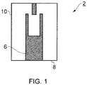
- a standard building block of cavity filters is a combline resonator structure 2, depicted in its basic form in Figure 1 .
- a resonator post 6 is grounded on the bottom 8 of a resonator cavity 10. It will be understood that the nomenclature top wall, bottom wall, side walls, is intended to distinguish the walls from each other and resonators may function in any orientation relative to the Earth.
- the resonator structure 2 resonates in known manner at a frequency where the resonator post 6 height is approximately one quarter-wavelength.
- Figure 2 illustrates a distributed re-entrant resonator structure 20, where (a) is cross-sectional top view and (b) is a cross-sectional front view.
- the resonator structure 20 has a cavity enclosure 22, a cavity 24 and a number of resonators 26A - 26D, and a tuner (not shown).
- Each resonator 26A - 26D has two parts, a resonator post 28A - 28D and a resonator cover 30A - 30D.
- Each resonator post 28A - 28D is grounded to one wall 32 of the cavity enclosure 22 and extends into the cavity 24.
- Each resonator cover 30A - 30D is grounded to an opposing wall 34 of the cavity enclosure 22 and extends into the cavity 24.
- all the resonator posts 28A - 28D protrude into the cavity 24 from one side/surface.
- the tuner (not shown) protrudes the cavity 24 from the opposite side.
- the resonators 26A - 26D resonate at a frequency where the resonator post 28A - 28D height is approximately one eighth-wavelength.
- a signal is received via an input signal feed (not shown) within the cavity 24.
- the input signal feed magnetically couples with a resonator post 28A - 28D.
- An electric current flows along the surface of the resonator post 28A - 28D and an electric field is generated at the open end of the resonator post 28A - 28D between that open end and the associated resonator cover 30A - 30D, which acts as a load on the resonator post 28A - 28D.
- the electric field is contained by the associated resonator cover 30A - 30D, which minimises electrical field coupling between resonator posts 28A - 28D.
- the magnetic field generated by the resonator post 28A - 28D in response to the input signal feed in turn magnetically couples across an inter-post gap 36 with adjacent resonator posts 28A - 28D.
- the magnetic coupling then continues between the resonator posts 28A - 28D and the signal distributes across the array.
- a filtered signal is then received at an output signal feed (not shown).
- Table 1 gives the physical dimensions of the resonator simulated.
- the volume of the resonator is 8.02 cm 3 .
- Table 2 shows the simulated performance of the example resonator.
- Table 1 Resonator dimensions Feature Dimension Circular Cavity (Diameter x Length) 3.2cm x 1.0 cm (8.02 cm 3 )
- Table 2 Simulated performance based on HFSS Eigenmode solver - the results are preliminary, not optimized Resonator Electrical Length @1800MHz (166.67 mm) Gap Size Resonant frequency Q-Factor (Au/Au) 5.4 ⁇ 10 07 S/m Figure 2 ⁇ 0.06 ⁇ 0 or ⁇ 21.6 deg 0.8 (mm) ⁇ 1850 MHz ⁇ 2250
- Figure 3 illustrates an interdigitated distributed re-entrant resonator structure 20A, where (a) is cross-sectional top view and (b) is a cross-sectional front view.
- the resonator structure 20A has a cavity enclosure 22, a cavity 24 and a number of resonators 26A' - 26D', and a tuner (not shown).
- Each resonator 26A' - 26D' has two parts, a resonator post 28A' - 28D' and a resonator cover 30A' - 30D'.
- Resonator posts 28A' and 28D' are grounded to one wall 32 of the cavity enclosure 22 and extend into the cavity 24.
- Resonator covers 30A' and 30D' are grounded to an opposing wall 34 of the cavity enclosure 22 and extend into the cavity 24.
- Resonator posts 28B' and 28C' are grounded to one wall 34 of the cavity enclosure 22 and extend into the cavity 24.
- Resonator covers 30B' and 30C' are grounded to an opposing wall 32 of the cavity enclosure 22 and extend into the cavity 24.
- the resonator posts 28A' - 28D' protrude into the cavity 24 from alternating sides/surfaces as an interdigitated arrangement.
- the tuner (not shown) protrudes the cavity 24 from one side.
- a signal is received via an input signal feed (not shown) within the cavity 24.
- the input signal feed magnetically couples with a resonator post 28A' - 28D'.
- An electric current flows along the surface of the resonator post 28A' - 28D' and an electric field is generated at the open end of the resonator post 28A' - 28D' between that open end and the associated resonator cover 30A' - 30D', which acts as a load on the resonator post 28A' - 28D'.
- the electric field is contained by the associated resonator cover 30A' - 30D' and adjacent resonator covers 30A' - 30D' are spatially separated, which minimises electrical field coupling between resonator posts 28A' - 28D'.
- the magnetic field generated by the resonator post 28A' - 28D' in response to the input signal feed in turn magnetically couples across an inter-post gap 36' with adjacent resonator posts 28A' - 28D'.
- the magnetic coupling then continues between the resonator posts 28A' - 28D' and the signal distributes across the array.
- a filtered signal is then received at an output signal feed (not shown).
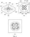
- Figure 4 illustrates a distributed re-entrant resonator structure 20", where (a) is cross-sectional perspective view, (b) is a cross-sectional top view and (c) illustrates the magnetic field distribution.
- the resonator structure 20" has a cavity enclosure 22", a cavity 24" and a number of resonators 26A" - 26D", and a tuner 40.
- Each resonator 26A" - 26D" has two parts, a resonator post 28A" - 28D” and a resonator cover 30A" - 30D".
- Each resonator post 28A" - 28D” is grounded to one wall (not shown) of the cavity enclosure 22" and extends into the cavity 24.
- Each resonator cover 30A" - 30D" is grounded to an opposing wall 34" of the cavity enclosure 22" and extends into the cavity 24". Hence, all the resonator posts 28A - 28D” protrude into the cavity 24" from one side/surface.
- a signal is received via an input signal feed (not shown) within the cavity 24".
- the input signal feed magnetically couples with a resonator post 28A" - 28D".
- An electric current flows along the surface of the resonator post 28A" - 28D” and an electric field is generated at the open end of the resonator post 28A" - 28D" between that open end and the associated resonator cover 30A" - 30D", which acts as a load on the resonator post 28A" - 28D".
- the electric field is contained by the associated resonator cover 30A" - 30D", which minimises electrical field coupling between resonator posts 28A" - 28D".
- the magnetic field generated by the resonator post 28A" - 28D" in response to the input signal feed in turn magnetically couples across an inter-post gap 36" with adjacent resonator posts 28A" - 28D".
- the magnetic coupling then continues between the resonator posts 28A" - 28D” and the signal distributes across the array.
- a filtered signal is then received at an output signal feed (not shown).
- the resonators 26A" - 26D" can be interdigitated as mentioned above or can even be arbitrarily interdigitated.
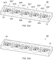
- Figure 5(a) is a cross-sectional perspective view of a filter arrangement 80 of the re-entrant resonator structure modules mentioned above.
- 5 modules 20"A - 20"E are utilised, with inter-module apertures 90A - 90D provided for magnetic coupling therebetween.
- a signal is received via an input signal feed 60 within the cavity 34"A.
- the input signal feed magnetically couples with the resonator posts.
- Resonator posts within the cavity 34"A magnetically couple with resonator posts within the cavity 34"B via the aperture 90A, which in turn couple with resonator posts within the cavity 34"C via the aperture 90B, and so on.
- a filtered signal is then received at an output signal feed 70.
- re-entrant resonator structure modules may be provided and that they need not all be identical in configuration. It will also be appreciated that fewer or more than 4 resonators may be provided and that they may be arranged in different configurations, as mentioned above.
- Figure 5(b) is a cross-sectional perspective view of a filter arrangement 80' of the re-entrant resonator structure modules mentioned above. This arrangement is identical to that illustrated in Figure 5(a) , with the exception of slightly different configuration input signal feed 60' and output signal feed 70'.
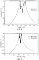
- Figure 8 is a shows the simulated response of the filter shown in Figure 5(a) .
- the resonator posts and the resonator covers are formed by a metallic structure (which may be the whole structure or a coating).
- a metallic structure which may be the whole structure or a coating
- embodiments also envisage forming at least some (or all) of the resonator posts from a ceramic (which may be the whole structure or a coating), with the remainder (if any) being formed from a metal.
- Figure 6 illustrates a distributed re-entrant resonator structure 20′′′, where (a) is cross-sectional perspective view, and (b) is a cross-sectional top view and (c) illustrates the magnetic field distribution.
- the resonator structure 20′′′ has a cavity enclosure 22′′′, a cavity 24′′′ and a number of resonators 26A′′′ - 26C′′′, and a tuner 40.
- Each resonator 26A′′′ - 26C′′′ has two parts, a resonator post 28A′′′ - 28C′′′ and a resonator cover 30A′′′ - 30C′′′.
- Each resonator post 28A′′′ - 28C′′′ is grounded to one wall (not shown) of the cavity enclosure 22′′′ and extends into the cavity 24′′′.
- Each resonator post 28A′′′ - 28C′′′ is ceramic.
- Each resonator cover 30A′′′ - 30C′′′ is a metallic hollow cylinder and is grounded to an opposing wall 34′′′ of the cavity enclosure 22′′′ and extends into the cavity 24′′′. Hence, all the resonator posts 28A′′′ - 28C′′′ protrude into the cavity 24′′′ from one side/surface.
- a signal is received via an input signal feed (not shown) within the cavity 24′′′.
- the input signal feed magnetically couples with a resonator post 28A′′′ - 28C′′′.
- An electric current flows along the surface of the resonator post 28A′′′ - 28C′′′ and an electric field is generated at the open end of the resonator post 28A′′′ - 28C′′′ between that open end and the associated resonator cover 30A′′′ - 30′′′, which acts as a load on the resonator post 28A′′′ - 28C′′′.
- the electric field is contained by the associated resonator cover 30A′′′ - 30C′′′, which minimises electrical field coupling between resonator posts 28A′′′ - 28C′′′.
- the magnetic field generated by the resonator post 28A′′′ - 28C′′′ in response to the input signal feed in turn magnetically couples across an inter-post gap 36′′′ with adjacent resonator posts 28A′′′ - 28C′′′.
- the magnetic coupling then continues between the resonator posts 28A′′′ - 28C′′′ and the signal distributes across the array.
- a filtered signal is then received at an output signal feed (not shown).
- the resonators 26A′′′ - 26C′′′ can be interdigitated as mentioned above or can even be arbitrarily interdigitated.
- Figure 7 is a cross-sectional perspective view of a filter arrangement 80' of the re-entrant resonator structure modules mentioned above.
- 5 modules 20′′′A - 20′′′E are utilised, with inter-module apertures 90'A - 90'D provided for magnetic coupling therebetween.
- a signal is received via an input signal feed 60' within the cavity 34′′′A.
- the input signal feed magnetically couples with the resonator posts.
- Resonator posts within the cavity 34′′′A magnetically couple with resonator posts within the cavity 34′′′B via the aperture 90'A, which in turn couple with resonator posts within the cavity 34′′′C via the aperture 90'B, and so on.
- a filtered signal is then received at an output signal feed 70'.
- re-entrant resonator structure modules may be provided and that they need not all be identical in configuration. It will also be appreciated that fewer or more than 3 resonators may be provided and that they may be arranged in different configurations, as mentioned above.
- Figure 9 is a shows the simulated response of the filter shown in Figure 7 . Its insertion loss is 0.32 dB at 2.47 GHz. The height of the resonators is only 10 mm.
- embodiments also provide:
- the resonator comprises a cavity enclosure, a cavity and numerous main elements (re-entrant resonators/posts), and a tuner.
- the re-entrant resonator has two parts, a post and a cover hat. The cover protrudes the cavity from the opposite side. All the re-entrant resonators protrude the cavity from one side/surface.
- the tuner protrudes the cavity from the opposite side.
- the posts are ceramic posts.
- the posts can be partly replaced by ceramic posts, the remaining being metallic.
- the performance characteristics of the ceramic re-entrant distributed resonator of embodiments is unique and demonstrates the extreme high performance of the resonator.
- Embodiments are utilised in a 5 pole filter scenario. All the resonator embodiments above may be fitted to the filter embodiments.
- all the posts are replaced by ceramic posts.
- the posts are partly replaced by ceramic posts.
- the posts are partly replaced by ceramic posts that extend the entire length of the cavity (TM ceramic resonator).
- the posts from one side of the cavity only are replaced by the ceramic posts.
- the number of resonators is selectable dependent on design requirements.
- the configuration of the resonators can vary dependent on design requirements.
- the resonators can be in an inline configuration, a rectangular grid, a circular grid, triangular grid, elliptical, or alike.
- the shape of resonator posts and re-entrant hats can also be arbitrary.
- the resonator caps are discontinuous (for example a quarter cylinder to shield only adjacent resonator caps) and only partially surround the resonator post. This simplifies manufacture and reduces weight.
- Embodiments simultaneously provide for reduced physical dimensions of cavity filters and improved performance of cavity filters. Both qualities are greatly valued in industrial applications. This is because filters are typically the bulkiest and heaviest subsystems in mobile cellular base stations, rivalled only by power-amplifier heatsinks. Therefore filter miniaturization is always desired. Embodiments offer high performance in these physical volume constraints.
- Embodiments provide a miniaturised resonator that simultaneously achieves size reduction and high performance. No known coaxial resonator at present manages to achieve these characteristics. In particular, for the same volume as a standard resonator depicted in Figure 1 , the presented embodiments of the miniaturised resonator achieve significant higher performance. A benefit of this technology is that it does allow the conventional machining of the filter cavity to be employed.
- the caps 30A ⁇ , 30B ⁇ contain the electric field between the resonator element 28A ⁇ , 28B ⁇ and its resonator cap 30A ⁇ , 30B ⁇ , thus preventing or reducing the electric field coupling between resonators. If there is both magnetic and electric coupling between two resonators, then they tend to cancel each other and reduce the total coupling between resonators.
- the resonator cap 30A ⁇ , 30B ⁇ contains the electric field by loading the resonator element 28A ⁇ , 28B ⁇ with the resonator cap 30A ⁇ , 30B ⁇ , which increases the total coupling between two resonators and improves performance.
- program storage devices e.g., digital data storage media, which are machine or computer readable and encode machine-executable or computer-executable programs of instructions, wherein said instructions perform some or all of the steps of said above-described methods.
- the program storage devices may be, e.g., digital memories, magnetic storage media such as a magnetic disks and magnetic tapes, hard drives, or optically readable digital data storage media.
- the embodiments are also intended to cover computers programmed to perform said steps of the above-described methods.
- processors may be provided through the use of dedicated hardware as well as hardware capable of executing software in association with appropriate software.
- the functions may be provided by a single dedicated processor, by a single shared processor, or by a plurality of individual processors, some of which may be shared.
- processor or “controller” or “logic” should not be construed to refer exclusively to hardware capable of executing software, and may implicitly include, without limitation, digital signal processor (DSP) hardware, network processor, application specific integrated circuit (ASIC), field programmable gate array (FPGA), read only memory (ROM) for storing software, random access memory (RAM), and non-volatile storage. Other hardware, conventional and/or custom, may also be included.
- DSP digital signal processor
- ASIC application specific integrated circuit
- FPGA field programmable gate array
- ROM read only memory
- RAM random access memory
- non-volatile storage Other hardware, conventional and/or custom, may also be included.
- any switches shown in the Figures are conceptual only. Their function may be carried out through the operation of program logic, through dedicated logic, through the interaction of program control and dedicated logic, or even manually, the particular technique being selectable by the implementer as more specifically understood from the context.
- any block diagrams herein represent conceptual views of illustrative circuitry embodying the principles of the invention.
- any flow charts, flow diagrams, state transition diagrams, pseudo code, and the like represent various processes which may be substantially represented in computer readable medium and so executed by a computer or processor, whether or not such computer or processor is explicitly shown.
Landscapes
- Physics & Mathematics (AREA)
- Electromagnetism (AREA)
- Control Of Motors That Do Not Use Commutators (AREA)
Description
- The present invention relates to a resonator for telecommunications. Embodiments relate to a resonator assembly for radio frequency (RF) filters and a method.
- Filters are widely used in telecommunications. Their applications vary from mobile cellular base stations, through radar systems, amplifier linearization, to point-to-point radio and RF signal cancellation, to name a few. The choice of a filter is ultimately dependent on the application; however, there are certain desirable characteristics that are common to all filter realisations. For example, the amount of insertion loss in the pass-band of the filter should be as low as possible, while the attenuation in the stop-band should be as high as possible. Further, in some applications, the guard band - the frequency separation between the pass-band and stop-band - needs to be very small, which requires filters of high-order to be deployed in order to achieve this requirement. However, the requirement for a high-order filter is always accompanied by an increase in the cost (due to a greater number of components that a filter requires) and size. Furthermore, even though increasing the order of the filter increases the attenuation in the stop-band, this inevitably increases the losses in the pass-band.
- One of the challenging tasks in filter design is filter size reduction with a simultaneous retention of excellent electrical performance comparable with larger structures. One of the main parameters governing filter's selectivity and insertion loss is the so-called quality factor of the elements comprising the filter - "Q factor". The Q factor is defined as the ratio of energy stored in the element to the time-averaged power loss. For lumped elements that are used particularly at low RF frequencies for filter design, Q is typically in the range of ~ 60-100 whereas, for cavity type resonators, Q can be as high as several 1000s. Although lumped components offer significant miniaturization, their low Q factor prohibits their use in highly-demanding applications where high rejection and/or selectivity is required. On the other hand, cavity resonators offer sufficient Q, but their size prevents their use in many applications. The miniaturization problem is particularly pressing with the advent of small cells, where the volume of the base station should be minimal, since it is important the base station be as inconspicuous as possible (as opposed to an eyesore). Moreover, the currently-observed trend of macrocell base stations lies with multiband solutions within a similar mechanical envelope to that of single-band solutions without sacrificing the system's performance.
- For the high-medium power base station filter applications, with an emphasis on the lower-end of the frequency spectrum (e.g., 700 MHz), the physical volume and weight of RF hardware equipment poses significant challenges (cost, deployment, etc.) to the network equipment manufactures/providers. The technical problem described above, comes as a consequence of the fact that the RF system electrical requirements impose stringent specification requirements on the filter electrical performance (e.g. isolation requirements in duplexers). This imposes in turn, increased physical size, insertion loss, with regards to the electrical/physical properties but also higher cost (manufacturing, assembly, tuning, etc.).
-
KR 2008 0089782 A US 4 660 005 discloses a high frequency electrical network in the form of a closedcavity 1 having two end plates between which extend four quarter wave resonators. - Accordingly, it is desired to minimize the physical size and profile of cavity resonators/filters (that can offer the high Q), focusing on a low-profile suitable also for small-cell outdoor products.
- According to a first aspect, there is provided a resonator assembly, as claimed in
claim 1. - The first aspect recognises that the height and density of resonators within a resonant structure is constrained by the operation of those resonators. For example, the first aspect recognises that in a conventional arrangement, the height is typically constrained to approximately a quarter wavelength at the operating frequency and the proximity of resonators is constrained by the presence of an electric field at the open end of the resonator.
- The features defined in
claim 1 provide compact resonator assembly having high operational performance. The provision of resonators having resonator elements and resonator caps helps to reduce the height of the resonator assembly to around one eighth of the operating wavelength. The provision of the resonator caps helps to contain the electrical field from the resonator elements, which enables adjacent resonator elements to be located closer together to provide for enhanced magnetic field coupling therebetween. - In one embodiment, the second resonator element has a second grounded end and a second open end, the second resonator element being grounded at the second grounded end on one of the first wall and the second wall and extending into the resonant chamber, and the second resonator cap has a second grounded portion and a second open portion, the second resonator cap being grounded at the second grounded portion on another one of the first wall and second wall, the second resonator cap extending into the resonant chamber to at least partially surround the second open end of the second resonator element with the second open portion for electrical field loading of the second resonator element by the second resonator cap. Accordingly, the resonator elements may either extend from the same wall or extend from differing walls. Likewise, the resonator caps may extend from the same wall or from differing walls.
- In one embodiment, the assembly comprises at least one further resonator, each comprising a further resonator element and a further resonator cap, adjacent resonator elements being located for magnetic field coupling therebetween. Accordingly, one or more additional resonators may be provided, positioned for magnetic field coupling between adjacent resonator elements.
- Embodiments recognise that using such assemblies at high frequencies requires a significant performance improvement as the frequency increases and is particularly demanding for 5G bands (3.5 GHz). Accordingly, in one embodiment, the resonator elements each are one of metallic and ceramic. Accordingly, the resonator elements may be either made of a metal or a ceramic.
- In one embodiment, at least one resonator element is ceramic and at least one resonator element is metallic. Accordingly, some of the resonator elements may be either made a ceramic, with the remaining resonator elements being made of a metal.
- In one embodiment, the resonator caps are metallic. Accordingly, the resonator caps may be made of a metal.
- In one embodiment, the resonator elements each comprise an elongate post. It will be appreciated that the effective electrical length of the resonator elements can be adjusted, depending on the design requirements.
- In one embodiment, the resonator elements each have an effective electrical length of around 1/32 of an operating wavelength of the resonator assembly
- In one embodiment, the resonator caps each surround a respective resonator element. Accordingly, the caps may completely surround an associated resonator element.
- In one embodiment, the resonator caps each comprise a tube extending at least partially along an axial length of a respective resonator element. Accordingly, the resonator caps may be formed as a tube within which the resonator element may be at least partially received.
- In one embodiment, an internal shape of the resonator caps each match an external shape of a respective resonator element. Having similar shaped caps and elements helps provide for a more uniform electric field and reduces current concentration.
- In one embodiment, a cross-sectional shape of at least one of the resonator caps and the resonator elements are one of circular, rectangular and elliptical.
- In one embodiment, an inner cross-sectional shape and an outer cross-sectional shape of at least one of the resonator caps and the resonator elements differ. Accordingly, the shape profile of the inner surface and the shape profile of the outer surface may be different
- In one embodiment, the resonator caps are unitary. Accordingly, the resonator caps may be formed from a single common structure. This helps to reduce the complexity of assembling the resonator assembly.
- In one embodiment, each resonator is arranged in at least one of a linear, triangular grid, circular grid, rectangular grid and elliptical grid layout for magnetic field coupling between adjacent resonator elements. Accordingly, a variety of different layouts may be utilised, depending upon design requirements.
- In one embodiment, each resonator is arranged in a skewed grid layout for magnetic field coupling between adjacent resonator elements.
- In one embodiment, the apparatus comprises a plurality of adjacent resonant chambers, each having a plurality of the resonators. Accordingly, one or more adjacent resonant chambers may be arranged, typically having coupling apertures therebetween, in order to build a filter with the required characteristics.
- According to a second aspect, there is provided a method of radio frequency filtering, comprising passing a signal for filtering through a resonant assembly of the first aspect.
- Further particular and preferred aspects are set out in the accompanying independent and dependent claims.
- Where an apparatus feature is described as being operable to provide a function, it will be appreciated that this includes an apparatus feature which provides that function or which is adapted or configured to provide that function.
- Embodiments of the present invention will now be described further, with reference to the accompanying drawings, in which:
-
Figure 1 illustrates a basic form of a combline resonator structure; -
Figure 2 illustrates a distributed re-entrant resonator structure according to one embodiment where (a) is cross-sectional top view and (b) is a cross-sectional front view; -
Figure 3 illustrates an interdigitated distributed re-entrant resonator structure according to one embodiment where (a) is cross-sectional top view and (b) is a cross-sectional front view; -
Figure 4 illustrates a distributed re-entrant resonator structure according to one embodiment where (a) is cross-sectional perspective view, (b) is a cross-sectional top view and (c) illustrates the magnetic field distribution; -
Figures 5(a) and 5(b) are cross-sectional perspective views of a filter arrangement of the re-entrant resonator structure modules according to one embodiment; -
Figure 6 illustrates a distributed re-entrant resonator structure according to one embodiment where (a) is cross-sectional perspective view, and (b) is a cross-sectional top view and (c) illustrates the magnetic field distribution; -
Figure 7 is a cross-sectional perspective view of a filter arrangement of the re-entrant resonator structure modules according to one embodiment; -
Figure 8 and 9 show the simulated response of the filter shown inFigure 5(a) and7 , respectively; and -
Figure 10 illustrates schematically the magnetic field and electrical fields according to one embodiment. - Before discussing the embodiments in any more detail, first an overview will be provided. Embodiments provide for a high-performance, compact resonator assembly. The provision of a resonator formed by a resonator element and a resonator cap enables the height of the resonator assembly to be reduced significantly, typically from around a quarter wavelength to one eighth of the wavelength at the operating frequency. Also, the provision of the resonator cap helps to contain an electric field generated by the resonator element, which enables adjacent resonator elements to be located closer together in a more unconstrained manner, which provides for a more compact arrangement and enhanced magnetic coupling therebetween. Using this structure, it is possible to locate the resonators on differing walls of the resonant chamber in order to further isolate electric fields and enhance magnetic coupling between the resonator elements. The number and layout of the resonator elements is not constrained and can be selected based on the design requirements. Also, multiple resonant chambers, each having their own configuration or identical configurations, can be placed adjacent each other in order to build a filter having the required characteristics.
- In mobile cellular communication base stations, cavity filters are preferable (in terms of cost, technological maturity, market availability, etc.). A standard building block of cavity filters is a
combline resonator structure 2, depicted in its basic form inFigure 1 . Aresonator post 6 is grounded on thebottom 8 of a resonator cavity 10. It will be understood that the nomenclature top wall, bottom wall, side walls, is intended to distinguish the walls from each other and resonators may function in any orientation relative to the Earth. In operation, theresonator structure 2 resonates in known manner at a frequency where theresonator post 6 height is approximately one quarter-wavelength. -
Figure 2 illustrates a distributedre-entrant resonator structure 20, where (a) is cross-sectional top view and (b) is a cross-sectional front view. Theresonator structure 20 has acavity enclosure 22, acavity 24 and a number ofresonators 26A - 26D, and a tuner (not shown). Eachresonator 26A - 26D has two parts, aresonator post 28A - 28D and aresonator cover 30A - 30D. Eachresonator post 28A - 28D is grounded to onewall 32 of thecavity enclosure 22 and extends into thecavity 24. Eachresonator cover 30A - 30D is grounded to an opposingwall 34 of thecavity enclosure 22 and extends into thecavity 24. Hence, all the resonator posts 28A - 28D protrude into thecavity 24 from one side/surface. The tuner (not shown) protrudes thecavity 24 from the opposite side. In operation, theresonators 26A - 26D resonate at a frequency where theresonator post 28A - 28D height is approximately one eighth-wavelength. - This arrangement brings a range of benefits which include:
- 1. Low-cost - by adopting deep-drawn pieces for the resonator covers 30A - 30D of each
resonator 26A - 26D. The resonator covers 30A - 30D are attached with screws to opposingwall 34 of thecavity enclosure 22. - 2. Low manufacturing complexity - by not requiring machining on both sides of the cavity enclosure 22 - machining may even not be required once all the
resonator post 28A - 28D are screwed to thewall 32 of thecavity enclosure 22 and the resonator covers 30A - 30D are deep-drawn pieces that are also screwed on the opposingwall 34 of thecavity enclosure 22. - 3. Easy of tuning - requires only a single tuner (not shown)
- 4. Miniaturization factor - reduced frequency of operation with the same number of
resonators 26A - 26D (e.g. 4 resonators). - 5. Retain high performance - comparable performance as compared to the conventional resonator structure.
- 6. Significant reduced physical volume - reduced profile and volume as compared to the conventional resonator structure.
- In operation, a signal is received via an input signal feed (not shown) within the
cavity 24. The input signal feed magnetically couples with aresonator post 28A - 28D. An electric current flows along the surface of theresonator post 28A - 28D and an electric field is generated at the open end of theresonator post 28A - 28D between that open end and the associatedresonator cover 30A - 30D, which acts as a load on theresonator post 28A - 28D. The electric field is contained by the associatedresonator cover 30A - 30D, which minimises electrical field coupling betweenresonator posts 28A - 28D. The magnetic field generated by theresonator post 28A - 28D in response to the input signal feed in turn magnetically couples across aninter-post gap 36 with adjacent resonator posts 28A - 28D. The magnetic coupling then continues between the resonator posts 28A - 28D and the signal distributes across the array. A filtered signal is then received at an output signal feed (not shown). - This arrangement was then simulated with HFSS using a circular cavity. Table 1 gives the physical dimensions of the resonator simulated. The volume of the resonator is 8.02 cm3. Table 2 shows the simulated performance of the example resonator.
Table 1: Resonator dimensions Feature Dimension Circular Cavity (Diameter x Length) 3.2cm x 1.0 cm (8.02 cm3) Resonator Post - Resonator Cover - Post/Cover Gap 9.2 mm / 5.2 mm / 0.8 mm Table 2: Simulated performance based on HFSS Eigenmode solver - the results are preliminary, not optimized Resonator Electrical Length @1800MHz (166.67 mm) Gap Size Resonant frequency Q-Factor (Au/Au) 5.4×1007 S/m Figure 2 ∼0.06 λ0 or ∼21.6 deg 0.8 (mm) ∼1850 MHz ∼ 2250 -
Figure 3 illustrates an interdigitated distributedre-entrant resonator structure 20A, where (a) is cross-sectional top view and (b) is a cross-sectional front view. Theresonator structure 20A has acavity enclosure 22, acavity 24 and a number ofresonators 26A' - 26D', and a tuner (not shown). Eachresonator 26A' - 26D' has two parts, aresonator post 28A' - 28D' and aresonator cover 30A' - 30D'. Resonator posts 28A' and 28D' are grounded to onewall 32 of thecavity enclosure 22 and extend into thecavity 24. Resonator covers 30A' and 30D' are grounded to an opposingwall 34 of thecavity enclosure 22 and extend into thecavity 24. Resonator posts 28B' and 28C' are grounded to onewall 34 of thecavity enclosure 22 and extend into thecavity 24. Resonator covers 30B' and 30C' are grounded to an opposingwall 32 of thecavity enclosure 22 and extend into thecavity 24. Hence, the resonator posts 28A' - 28D' protrude into thecavity 24 from alternating sides/surfaces as an interdigitated arrangement. The tuner (not shown) protrudes thecavity 24 from one side. - In operation, a signal is received via an input signal feed (not shown) within the
cavity 24. The input signal feed magnetically couples with aresonator post 28A' - 28D'. An electric current flows along the surface of theresonator post 28A' - 28D' and an electric field is generated at the open end of theresonator post 28A' - 28D' between that open end and the associatedresonator cover 30A' - 30D', which acts as a load on theresonator post 28A' - 28D'. The electric field is contained by the associatedresonator cover 30A' - 30D' and adjacent resonator covers 30A' - 30D' are spatially separated, which minimises electrical field coupling betweenresonator posts 28A' - 28D'. The magnetic field generated by theresonator post 28A' - 28D' in response to the input signal feed in turn magnetically couples across an inter-post gap 36' withadjacent resonator posts 28A' - 28D'. The magnetic coupling then continues between the resonator posts 28A' - 28D' and the signal distributes across the array. A filtered signal is then received at an output signal feed (not shown). -
Figure 4 illustrates a distributedre-entrant resonator structure 20", where (a) is cross-sectional perspective view, (b) is a cross-sectional top view and (c) illustrates the magnetic field distribution. Theresonator structure 20" has acavity enclosure 22", acavity 24" and a number ofresonators 26A" - 26D", and atuner 40. Eachresonator 26A" - 26D" has two parts, aresonator post 28A" - 28D" and aresonator cover 30A" - 30D". Eachresonator post 28A" - 28D" is grounded to one wall (not shown) of thecavity enclosure 22" and extends into thecavity 24. Eachresonator cover 30A" - 30D" is grounded to an opposingwall 34" of thecavity enclosure 22" and extends into thecavity 24". Hence, all the resonator posts 28A - 28D" protrude into thecavity 24" from one side/surface. - In operation, a signal is received via an input signal feed (not shown) within the
cavity 24". The input signal feed magnetically couples with aresonator post 28A" - 28D". An electric current flows along the surface of theresonator post 28A" - 28D" and an electric field is generated at the open end of theresonator post 28A" - 28D" between that open end and the associatedresonator cover 30A" - 30D", which acts as a load on theresonator post 28A" - 28D". The electric field is contained by the associatedresonator cover 30A" - 30D", which minimises electrical field coupling betweenresonator posts 28A" - 28D". As shown inFigure 4(c) , the magnetic field generated by theresonator post 28A" - 28D" in response to the input signal feed in turn magnetically couples across aninter-post gap 36" withadjacent resonator posts 28A" - 28D". The magnetic coupling then continues between the resonator posts 28A" - 28D" and the signal distributes across the array. A filtered signal is then received at an output signal feed (not shown). - In this embodiment the
resonators 26A" - 26D" can be interdigitated as mentioned above or can even be arbitrarily interdigitated. -
Figure 5(a) is a cross-sectional perspective view of afilter arrangement 80 of the re-entrant resonator structure modules mentioned above. In this example, 5modules 20"A - 20"E are utilised, withinter-module apertures 90A - 90D provided for magnetic coupling therebetween. - In operation, a signal is received via an
input signal feed 60 within thecavity 34"A. The input signal feed magnetically couples with the resonator posts. Resonator posts within thecavity 34"A magnetically couple with resonator posts within thecavity 34"B via theaperture 90A, which in turn couple with resonator posts within thecavity 34"C via theaperture 90B, and so on. A filtered signal is then received at anoutput signal feed 70. - It will be appreciated that fewer or more re-entrant resonator structure modules may be provided and that they need not all be identical in configuration. It will also be appreciated that fewer or more than 4 resonators may be provided and that they may be arranged in different configurations, as mentioned above.
-
Figure 5(b) is a cross-sectional perspective view of a filter arrangement 80' of the re-entrant resonator structure modules mentioned above. This arrangement is identical to that illustrated inFigure 5(a) , with the exception of slightly different configuration input signal feed 60' and output signal feed 70'. -
Figure 8 is a shows the simulated response of the filter shown inFigure 5(a) . - In the embodiments mentioned above, the resonator posts and the resonator covers are formed by a metallic structure (which may be the whole structure or a coating). However, embodiments also envisage forming at least some (or all) of the resonator posts from a ceramic (which may be the whole structure or a coating), with the remainder (if any) being formed from a metal.
-
Figure 6 illustrates a distributedre-entrant resonator structure 20‴, where (a) is cross-sectional perspective view, and (b) is a cross-sectional top view and (c) illustrates the magnetic field distribution. Theresonator structure 20‴ has acavity enclosure 22‴, acavity 24‴ and a number ofresonators 26A‴ - 26C‴, and atuner 40. Eachresonator 26A‴ - 26C‴ has two parts, aresonator post 28A‴ - 28C‴ and aresonator cover 30A‴ - 30C‴. Eachresonator post 28A‴ - 28C‴ is grounded to one wall (not shown) of thecavity enclosure 22‴ and extends into thecavity 24‴. Eachresonator post 28A‴ - 28C‴ is ceramic. Eachresonator cover 30A‴ - 30C‴ is a metallic hollow cylinder and is grounded to an opposingwall 34‴ of thecavity enclosure 22‴ and extends into thecavity 24‴. Hence, all the resonator posts 28A‴ - 28C‴ protrude into thecavity 24‴ from one side/surface. - In operation, a signal is received via an input signal feed (not shown) within the
cavity 24‴. The input signal feed magnetically couples with aresonator post 28A‴ - 28C‴. An electric current flows along the surface of theresonator post 28A‴ - 28C‴ and an electric field is generated at the open end of theresonator post 28A‴ - 28C‴ between that open end and the associatedresonator cover 30A‴ - 30‴, which acts as a load on theresonator post 28A‴ - 28C‴. The electric field is contained by the associatedresonator cover 30A‴ - 30C‴, which minimises electrical field coupling betweenresonator posts 28A‴ - 28C‴. As shown inFigure 6(c) , the magnetic field generated by theresonator post 28A‴ - 28C‴ in response to the input signal feed in turn magnetically couples across aninter-post gap 36‴ withadjacent resonator posts 28A‴ - 28C‴. The magnetic coupling then continues between the resonator posts 28A‴ - 28C‴ and the signal distributes across the array. A filtered signal is then received at an output signal feed (not shown). - In this embodiment the
resonators 26A‴ - 26C‴ can be interdigitated as mentioned above or can even be arbitrarily interdigitated. -
Figure 7 is a cross-sectional perspective view of a filter arrangement 80' of the re-entrant resonator structure modules mentioned above. In this example, 5modules 20‴A - 20‴E are utilised, with inter-module apertures 90'A - 90'D provided for magnetic coupling therebetween. - In operation, a signal is received via an input signal feed 60' within the
cavity 34‴A. The input signal feed magnetically couples with the resonator posts. Resonator posts within thecavity 34‴A magnetically couple with resonator posts within thecavity 34‴B via the aperture 90'A, which in turn couple with resonator posts within thecavity 34‴C via the aperture 90'B, and so on. A filtered signal is then received at an output signal feed 70'. - It will be appreciated that fewer or more re-entrant resonator structure modules may be provided and that they need not all be identical in configuration. It will also be appreciated that fewer or more than 3 resonators may be provided and that they may be arranged in different configurations, as mentioned above.
-
Figure 9 is a shows the simulated response of the filter shown inFigure 7 . Its insertion loss is 0.32 dB at 2.47 GHz. The height of the resonators is only 10 mm. - Embodiments utilising ceramics provide remarkable benefits:
- 1. High performance - Ceramic material will allow for significant increase in the Q-factor.
- 2. High frequency/High performance - The improvement will be more and more pronounced as the frequency goes higher.
- In addition, embodiments also provide:
- 3. Low-cost - adopting deep drawn pieces for the top part of the re-entrant resonator (the re-entrant resonators, can be separately made out of deep-drawn pieces and then attached with screws at the lid of the cavity).
- 4. Low manufacturing complexity - does not require machining on both sides - machining can be not even required once all the bottom elements are screwed to the bottom of the cavity and the top elements are deep-drawn pieces that are also screwed on the lid of the cavity filter.
- 5. Ease of tuning - requires only a single tuner.
- 6. Miniaturization factor - with the same number of elements (e.g. 4 elements) reduced frequency of operation.
- 7. Significant reduced physical volume - (reduced profile and volume).
- In one embodiment, the resonator comprises a cavity enclosure, a cavity and numerous main elements (re-entrant resonators/posts), and a tuner. The re-entrant resonator has two parts, a post and a cover hat. The cover protrudes the cavity from the opposite side. All the re-entrant resonators protrude the cavity from one side/surface. The tuner protrudes the cavity from the opposite side. The posts are ceramic posts.
- In embodiments, the posts can be partly replaced by ceramic posts, the remaining being metallic. The performance characteristics of the ceramic re-entrant distributed resonator of embodiments is unique and demonstrates the extreme high performance of the resonator.
- Embodiments are utilised in a 5 pole filter scenario. All the resonator embodiments above may be fitted to the filter embodiments.
- In embodiments, all the posts are replaced by ceramic posts. In embodiments, the posts are partly replaced by ceramic posts. In embodiments, the posts are partly replaced by ceramic posts that extend the entire length of the cavity (TM ceramic resonator). In embodiments, the posts from one side of the cavity only are replaced by the ceramic posts.
- In embodiments, different resonator configurations are envisaged:
- 1. Number of elements: The number of the elements can be arbitrary.
- 2. Grid: The configuration of the elements can vary. Can be in an inline configuration, rectangular grid, in a circular grid, elliptical, or alike. A skewed grid can also be considered.
- 3. Shape of posts and re-entrant hats. The shape can also be arbitrary, can be a circular one, rectangular, elliptical or alike.
- 4. The shape can be different from the inner side and from the outer side. For, example the re-entrant hat can be made rectangular outside and circular inside, or the opposite.
- In embodiments, the number of resonators is selectable dependent on design requirements. Also, the configuration of the resonators can vary dependent on design requirements. For example, the resonators can be in an inline configuration, a rectangular grid, a circular grid, triangular grid, elliptical, or alike. Furthermore, the shape of resonator posts and re-entrant hats can also be arbitrary. For example, the can be circular, rectangular, elliptical or alike. In one embodiment, the resonator caps are discontinuous (for example a quarter cylinder to shield only adjacent resonator caps) and only partially surround the resonator post. This simplifies manufacture and reduces weight.
- Embodiments simultaneously provide for reduced physical dimensions of cavity filters and improved performance of cavity filters. Both qualities are greatly valued in industrial applications. This is because filters are typically the bulkiest and heaviest subsystems in mobile cellular base stations, rivalled only by power-amplifier heatsinks. Therefore filter miniaturization is always desired. Embodiments offer high performance in these physical volume constraints.
- Embodiments provide a miniaturised resonator that simultaneously achieves size reduction and high performance. No known coaxial resonator at present manages to achieve these characteristics. In particular, for the same volume as a standard resonator depicted in
Figure 1 , the presented embodiments of the miniaturised resonator achieve significant higher performance. A benefit of this technology is that it does allow the conventional machining of the filter cavity to be employed. - As illustrated in
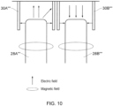
Figure 10 , in embodiments, the caps 30Aʺʺ, 30Bʺʺ contain the electric field between the resonator element 28Aʺʺ, 28Bʺʺ and its resonator cap 30Aʺʺ, 30Bʺʺ, thus preventing or reducing the electric field coupling between resonators. If there is both magnetic and electric coupling between two resonators, then they tend to cancel each other and reduce the total coupling between resonators. In embodiments, the resonator cap 30Aʺʺ, 30Bʺʺ contains the electric field by loading the resonator element 28Aʺʺ, 28Bʺʺ with the resonator cap 30Aʺʺ, 30Bʺʺ, which increases the total coupling between two resonators and improves performance. - A person of skill in the art would readily recognize that steps of various above-described methods can be performed by programmed computers. Herein, some embodiments are also intended to cover program storage devices, e.g., digital data storage media, which are machine or computer readable and encode machine-executable or computer-executable programs of instructions, wherein said instructions perform some or all of the steps of said above-described methods. The program storage devices may be, e.g., digital memories, magnetic storage media such as a magnetic disks and magnetic tapes, hard drives, or optically readable digital data storage media. The embodiments are also intended to cover computers programmed to perform said steps of the above-described methods.
- The functions of the various elements shown in the Figures, including any functional blocks labelled as "processors" or "logic", may be provided through the use of dedicated hardware as well as hardware capable of executing software in association with appropriate software. When provided by a processor, the functions may be provided by a single dedicated processor, by a single shared processor, or by a plurality of individual processors, some of which may be shared. Moreover, explicit use of the term "processor" or "controller" or "logic" should not be construed to refer exclusively to hardware capable of executing software, and may implicitly include, without limitation, digital signal processor (DSP) hardware, network processor, application specific integrated circuit (ASIC), field programmable gate array (FPGA), read only memory (ROM) for storing software, random access memory (RAM), and non-volatile storage. Other hardware, conventional and/or custom, may also be included. Similarly, any switches shown in the Figures are conceptual only. Their function may be carried out through the operation of program logic, through dedicated logic, through the interaction of program control and dedicated logic, or even manually, the particular technique being selectable by the implementer as more specifically understood from the context.
- It should be appreciated by those skilled in the art that any block diagrams herein represent conceptual views of illustrative circuitry embodying the principles of the invention. Similarly, it will be appreciated that any flow charts, flow diagrams, state transition diagrams, pseudo code, and the like represent various processes which may be substantially represented in computer readable medium and so executed by a computer or processor, whether or not such computer or processor is explicitly shown.
- The description and drawings merely illustrate the principles of the invention. It will thus be appreciated that those skilled in the art will be able to devise various arrangements that, although not explicitly described or shown herein, embody the principles of the invention and are included within its scope. Furthermore, all examples recited herein are principally intended expressly to be only for pedagogical purposes to aid the reader in understanding the principles of the invention and the concepts contributed by the inventor(s) to furthering the art, and are to be construed as being without limitation to such specifically recited examples and conditions.
Claims (14)
- A resonator assembly (20; 80), comprising:a resonant chamber (24) defined by a first wall (32), a second wall (34) opposing said first wall and side walls extending between said first wall and said second wall;a first resonator comprising a first resonator element (28A) and a first resonator cap (30A), said first resonator element having a first grounded end and an first open end, said first resonator element being grounded at said first grounded end on said first wall and extending into said resonant chamber, said first resonator cap having a first grounded portion and an first open portion, said first resonator cap being grounded at said first grounded portion on said second wall and extending into said resonant chamber to at least partially surround said first open end of said first resonator element with said first open portion for electrical field loading of said first resonator element by said first resonator cap; anda second resonator comprising a second resonator element (28C) and a second resonator cap (30C) located for electrical field loading of said second resonator element by said second resonator cap, said second resonator element being located for magnetic field coupling between said first resonator element and said second resonator element;wherein the height between the first and second walls of the resonator assembly is around one eighth of an operating wavelength of said resonator assembly, and wherein said resonator elements each have an effective electrical length of around one eighth of the operating wavelength.
- The resonator assembly of claim 1, wherein said second resonator element has a second grounded end and a second open end, said second resonator element being grounded at said second grounded end on one of said first wall and said second wall and extending into said resonant chamber, and said second resonator cap has a second grounded portion and a second open portion, said second resonator cap being grounded at said second grounded portion on another one of said first wall and second wall, said second resonator cap extending into said resonant chamber to at least partially surround said second open end of said second resonator element with said second open portion for electrical field loading of said second resonator element by and said second resonator cap.
- The resonator assembly of claim 1 or 2, comprising at least one further resonator, each comprising a further resonator element (28B; 28D) and a further resonator cap (30B; 30D), adjacent resonator elements being located for magnetic field coupling therebetween.
- The resonator assembly of any preceding claim, wherein each resonator element is one of metallic and ceramic.
- The resonator assembly of any preceding claim, wherein at least one resonator element is ceramic and at least one resonator element is metallic.
- The resonator assembly of any preceding claim, wherein said resonator caps are metallic.
- The resonator assembly of any preceding claim, wherein said resonator elements each comprise an elongate post.
- The resonator assembly of any preceding claim, wherein said resonator caps each surround a respective resonator element.
- The resonator assembly of any preceding claim, wherein said resonator caps each comprise a tube extending at least partially along an axial length of a respective resonator element.
- The resonator assembly of any preceding claim, wherein an internal shape of said resonator caps each match an external shape of a respective resonator element.
- The resonator assembly of any preceding claim, wherein said resonator caps are unitary.
- The resonator assembly of any preceding claim, wherein each resonator is arranged in at least one of a linear, triangular grid, circular grid, rectangular grid and elliptical grid layout for magnetic field coupling between adjacent resonator elements.
- The resonator assembly of any preceding claim, comprising a plurality of adjacent resonant chambers, each having a plurality of said resonators.
- A method of radio frequency filtering, comprising passing a signal for filtering through a resonant assembly as claimed in any preceding claim.
Applications Claiming Priority (2)
| Application Number | Priority Date | Filing Date | Title |
|---|---|---|---|
| EP16203430.0A EP3333967A1 (en) | 2016-12-12 | 2016-12-12 | Resonator |
| PCT/EP2017/082011 WO2018108733A1 (en) | 2016-12-12 | 2017-12-08 | Resonator |
Publications (2)
| Publication Number | Publication Date |
|---|---|
| EP3552268A1 EP3552268A1 (en) | 2019-10-16 |
| EP3552268B1 true EP3552268B1 (en) | 2023-03-22 |
Family
ID=57542870
Family Applications (2)
| Application Number | Title | Priority Date | Filing Date |
|---|---|---|---|
| EP16203430.0A Withdrawn EP3333967A1 (en) | 2016-12-12 | 2016-12-12 | Resonator |
| EP17816660.9A Active EP3552268B1 (en) | 2016-12-12 | 2017-12-08 | Resonator |
Family Applications Before (1)
| Application Number | Title | Priority Date | Filing Date |
|---|---|---|---|
| EP16203430.0A Withdrawn EP3333967A1 (en) | 2016-12-12 | 2016-12-12 | Resonator |
Country Status (3)
| Country | Link |
|---|---|
| US (1) | US11063335B2 (en) |
| EP (2) | EP3333967A1 (en) |
| WO (1) | WO2018108733A1 (en) |
Families Citing this family (4)
| Publication number | Priority date | Publication date | Assignee | Title |
|---|---|---|---|---|
| EP3997754B1 (en) | 2019-07-12 | 2023-12-06 | Telefonaktiebolaget Lm Ericsson (Publ) | Waveguide filters |
| EP3859893B1 (en) * | 2020-01-28 | 2023-08-09 | Nokia Solutions and Networks Oy | An antenna system |
| DE102020127767A1 (en) | 2020-10-21 | 2022-04-21 | Tesat-Spacecom Gmbh & Co. Kg | Waffle iron filter arrangement for high frequency signals |
| CN120016111B (en) * | 2025-04-07 | 2025-12-30 | 无锡华乾科技有限公司 | Miniaturized multichannel 5G anti-interference filter and design method thereof |
Family Cites Families (8)
| Publication number | Priority date | Publication date | Assignee | Title |
|---|---|---|---|---|
| GB2163009B (en) * | 1984-08-10 | 1987-11-04 | Marconi Co Ltd | High-frequency electrical network |
| KR20080088782A (en) | 2007-03-30 | 2008-10-06 | 삼성전자주식회사 | Thin film transistor array panel and manufacturing method thereof |
| KR100865727B1 (en) * | 2007-04-02 | 2008-10-28 | 주식회사 텔웨이브 | Resonators with Multiple Parallel Capacitors, Cavitation Filters and Bandpass Filters |
| EP2556559A4 (en) * | 2010-04-06 | 2014-07-09 | Powerwave Technologies Inc | Reduced size cavity filters for pico base stations |
| CN102097670A (en) * | 2011-02-18 | 2011-06-15 | 成都泰格微波技术股份有限公司 | Hybrid TM (Transverse Magnetic) mode dielectric filter |
| US9343790B2 (en) * | 2013-05-27 | 2016-05-17 | Jorge A. Ruiz-Cruz | Method of operation and construction of filters and multiplexers using multi-conductor multi-dielectric combline resonators |
| EP3012902A1 (en) * | 2014-10-21 | 2016-04-27 | Alcatel Lucent | A resonator, a filter and a method of radio frequency filtering |
| EP3012901B1 (en) * | 2014-10-21 | 2020-07-15 | Alcatel Lucent | A resonator, a radio frequency filter, and a method of filtering |
-
2016
- 2016-12-12 EP EP16203430.0A patent/EP3333967A1/en not_active Withdrawn
-
2017
- 2017-12-08 EP EP17816660.9A patent/EP3552268B1/en active Active
- 2017-12-08 US US16/468,893 patent/US11063335B2/en not_active Expired - Fee Related
- 2017-12-08 WO PCT/EP2017/082011 patent/WO2018108733A1/en not_active Ceased
Also Published As
| Publication number | Publication date |
|---|---|
| EP3552268A1 (en) | 2019-10-16 |
| WO2018108733A1 (en) | 2018-06-21 |
| US20200083590A1 (en) | 2020-03-12 |
| EP3333967A1 (en) | 2018-06-13 |
| US11063335B2 (en) | 2021-07-13 |
Similar Documents
| Publication | Publication Date | Title |
|---|---|---|
| US11063335B2 (en) | Resonator | |
| EP2814112A1 (en) | Resonant assembly | |
| EP3104453A1 (en) | A resonator assembly and filter | |
| Lee et al. | K-band frequency tunable substrate-integrated-waveguide resonator filter with enhanced stopband attenuation | |
| US20140347148A1 (en) | Method of operation and construction of filters and multiplexers using multi-conductor multi-dielectric combline resonators | |
| US20160134253A1 (en) | Operation frequency band customizable and frequency tunable filters with ebg substrates | |
| CN112467321B (en) | Dual-mode SIW (substrate integrated waveguide) adjustable filter based on reconfigurable electromagnetic boundary | |
| US10056665B2 (en) | Resonator assembly and filter | |
| EP2894710B1 (en) | Coaxial resonator filter | |
| Kumar et al. | Design of improved quadruple-mode bandpass filter using cavity resonator for 5G mid-band applications | |
| KR101315878B1 (en) | Dual mode dielectric resonator filter | |
| WO2014024349A1 (en) | Tm010 mode dielectric resonator, resonator element, and dielectric filter | |
| EP3012901B1 (en) | A resonator, a radio frequency filter, and a method of filtering | |
| CN116190950B (en) | A miniaturized dual coaxial cavity filter, its control method and application | |
| KR20160076019A (en) | Step impedance resonator with dielectric stack and filter using the same | |
| KR20090109445A (en) | Cylindrical Dielectric Resonator with Disk-shaped Groove and Using the Multimode Bandpass Filter | |
| EP4118706B1 (en) | Cavity filters and filter modules therefor | |
| KR102013056B1 (en) | Dielectric filter | |
| EP3089259B1 (en) | A resonator assembly and filter | |
| EP3285331B1 (en) | Resonator | |
| EP3179552B1 (en) | A resonator assembly, a radio frequency filter and a method of radio-frequency filtering | |
| EP3301752A1 (en) | Resonator | |
| EP3079198A1 (en) | A resonator assembly and filter | |
| Wu et al. | A Compact Multilayer HMSIW Bandpass Filter with Five Modes and Four Transmission Zeros | |
| EP2894709B1 (en) | Coaxial resonator filter |
Legal Events
| Date | Code | Title | Description |
|---|---|---|---|
| STAA | Information on the status of an ep patent application or granted ep patent |
Free format text: STATUS: UNKNOWN |
|
| STAA | Information on the status of an ep patent application or granted ep patent |
Free format text: STATUS: THE INTERNATIONAL PUBLICATION HAS BEEN MADE |
|
| PUAI | Public reference made under article 153(3) epc to a published international application that has entered the european phase |
Free format text: ORIGINAL CODE: 0009012 |
|
| STAA | Information on the status of an ep patent application or granted ep patent |
Free format text: STATUS: REQUEST FOR EXAMINATION WAS MADE |
|
| 17P | Request for examination filed |
Effective date: 20190712 |
|
| AK | Designated contracting states |
Kind code of ref document: A1 Designated state(s): AL AT BE BG CH CY CZ DE DK EE ES FI FR GB GR HR HU IE IS IT LI LT LU LV MC MK MT NL NO PL PT RO RS SE SI SK SM TR |
|
| AX | Request for extension of the european patent |
Extension state: BA ME |
|
| DAV | Request for validation of the european patent (deleted) | ||
| DAX | Request for extension of the european patent (deleted) | ||
| STAA | Information on the status of an ep patent application or granted ep patent |
Free format text: STATUS: EXAMINATION IS IN PROGRESS |
|
| 17Q | First examination report despatched |
Effective date: 20210324 |
|
| RIC1 | Information provided on ipc code assigned before grant |
Ipc: H01P 7/10 20060101ALN20220921BHEP Ipc: H01P 1/208 20060101ALN20220921BHEP Ipc: H01P 7/04 20060101ALI20220921BHEP Ipc: H01P 1/205 20060101AFI20220921BHEP |
|
| GRAP | Despatch of communication of intention to grant a patent |
Free format text: ORIGINAL CODE: EPIDOSNIGR1 |
|
| STAA | Information on the status of an ep patent application or granted ep patent |
Free format text: STATUS: GRANT OF PATENT IS INTENDED |
|
| RIC1 | Information provided on ipc code assigned before grant |
Ipc: H01P 7/10 20060101ALN20221004BHEP Ipc: H01P 1/208 20060101ALN20221004BHEP Ipc: H01P 7/04 20060101ALI20221004BHEP Ipc: H01P 1/205 20060101AFI20221004BHEP |
|
| INTG | Intention to grant announced |
Effective date: 20221102 |
|
| GRAS | Grant fee paid |
Free format text: ORIGINAL CODE: EPIDOSNIGR3 |
|
| GRAA | (expected) grant |
Free format text: ORIGINAL CODE: 0009210 |
|
| STAA | Information on the status of an ep patent application or granted ep patent |
Free format text: STATUS: THE PATENT HAS BEEN GRANTED |
|
| AK | Designated contracting states |
Kind code of ref document: B1 Designated state(s): AL AT BE BG CH CY CZ DE DK EE ES FI FR GB GR HR HU IE IS IT LI LT LU LV MC MK MT NL NO PL PT RO RS SE SI SK SM TR |
|
| REG | Reference to a national code |
Ref country code: GB Ref legal event code: FG4D |
|
| REG | Reference to a national code |
Ref country code: CH Ref legal event code: EP |
|
| REG | Reference to a national code |
Ref country code: DE Ref legal event code: R096 Ref document number: 602017067049 Country of ref document: DE |
|
| REG | Reference to a national code |
Ref country code: IE Ref legal event code: FG4D |
|
| REG | Reference to a national code |
Ref country code: AT Ref legal event code: REF Ref document number: 1555857 Country of ref document: AT Kind code of ref document: T Effective date: 20230415 |
|
| REG | Reference to a national code |
Ref country code: LT Ref legal event code: MG9D |
|
| REG | Reference to a national code |
Ref country code: NL Ref legal event code: MP Effective date: 20230322 |
|
| PG25 | Lapsed in a contracting state [announced via postgrant information from national office to epo] |
Ref country code: RS Free format text: LAPSE BECAUSE OF FAILURE TO SUBMIT A TRANSLATION OF THE DESCRIPTION OR TO PAY THE FEE WITHIN THE PRESCRIBED TIME-LIMIT Effective date: 20230322 Ref country code: NO Free format text: LAPSE BECAUSE OF FAILURE TO SUBMIT A TRANSLATION OF THE DESCRIPTION OR TO PAY THE FEE WITHIN THE PRESCRIBED TIME-LIMIT Effective date: 20230622 Ref country code: LT Free format text: LAPSE BECAUSE OF FAILURE TO SUBMIT A TRANSLATION OF THE DESCRIPTION OR TO PAY THE FEE WITHIN THE PRESCRIBED TIME-LIMIT Effective date: 20230322 Ref country code: HR Free format text: LAPSE BECAUSE OF FAILURE TO SUBMIT A TRANSLATION OF THE DESCRIPTION OR TO PAY THE FEE WITHIN THE PRESCRIBED TIME-LIMIT Effective date: 20230322 Ref country code: LV Free format text: LAPSE BECAUSE OF FAILURE TO SUBMIT A TRANSLATION OF THE DESCRIPTION OR TO PAY THE FEE WITHIN THE PRESCRIBED TIME-LIMIT Effective date: 20230322 |
|
| REG | Reference to a national code |
Ref country code: AT Ref legal event code: MK05 Ref document number: 1555857 Country of ref document: AT Kind code of ref document: T Effective date: 20230322 |
|
| PG25 | Lapsed in a contracting state [announced via postgrant information from national office to epo] |
Ref country code: SE Free format text: LAPSE BECAUSE OF FAILURE TO SUBMIT A TRANSLATION OF THE DESCRIPTION OR TO PAY THE FEE WITHIN THE PRESCRIBED TIME-LIMIT Effective date: 20230322 Ref country code: NL Free format text: LAPSE BECAUSE OF FAILURE TO SUBMIT A TRANSLATION OF THE DESCRIPTION OR TO PAY THE FEE WITHIN THE PRESCRIBED TIME-LIMIT Effective date: 20230322 Ref country code: GR Free format text: LAPSE BECAUSE OF FAILURE TO SUBMIT A TRANSLATION OF THE DESCRIPTION OR TO PAY THE FEE WITHIN THE PRESCRIBED TIME-LIMIT Effective date: 20230623 Ref country code: FI Free format text: LAPSE BECAUSE OF FAILURE TO SUBMIT A TRANSLATION OF THE DESCRIPTION OR TO PAY THE FEE WITHIN THE PRESCRIBED TIME-LIMIT Effective date: 20230322 |
|
| PG25 | Lapsed in a contracting state [announced via postgrant information from national office to epo] |
Ref country code: SM Free format text: LAPSE BECAUSE OF FAILURE TO SUBMIT A TRANSLATION OF THE DESCRIPTION OR TO PAY THE FEE WITHIN THE PRESCRIBED TIME-LIMIT Effective date: 20230322 Ref country code: RO Free format text: LAPSE BECAUSE OF FAILURE TO SUBMIT A TRANSLATION OF THE DESCRIPTION OR TO PAY THE FEE WITHIN THE PRESCRIBED TIME-LIMIT Effective date: 20230322 Ref country code: PT Free format text: LAPSE BECAUSE OF FAILURE TO SUBMIT A TRANSLATION OF THE DESCRIPTION OR TO PAY THE FEE WITHIN THE PRESCRIBED TIME-LIMIT Effective date: 20230724 Ref country code: ES Free format text: LAPSE BECAUSE OF FAILURE TO SUBMIT A TRANSLATION OF THE DESCRIPTION OR TO PAY THE FEE WITHIN THE PRESCRIBED TIME-LIMIT Effective date: 20230322 Ref country code: EE Free format text: LAPSE BECAUSE OF FAILURE TO SUBMIT A TRANSLATION OF THE DESCRIPTION OR TO PAY THE FEE WITHIN THE PRESCRIBED TIME-LIMIT Effective date: 20230322 Ref country code: AT Free format text: LAPSE BECAUSE OF FAILURE TO SUBMIT A TRANSLATION OF THE DESCRIPTION OR TO PAY THE FEE WITHIN THE PRESCRIBED TIME-LIMIT Effective date: 20230322 |
|
| PG25 | Lapsed in a contracting state [announced via postgrant information from national office to epo] |
Ref country code: SK Free format text: LAPSE BECAUSE OF FAILURE TO SUBMIT A TRANSLATION OF THE DESCRIPTION OR TO PAY THE FEE WITHIN THE PRESCRIBED TIME-LIMIT Effective date: 20230322 Ref country code: PL Free format text: LAPSE BECAUSE OF FAILURE TO SUBMIT A TRANSLATION OF THE DESCRIPTION OR TO PAY THE FEE WITHIN THE PRESCRIBED TIME-LIMIT Effective date: 20230322 Ref country code: IS Free format text: LAPSE BECAUSE OF FAILURE TO SUBMIT A TRANSLATION OF THE DESCRIPTION OR TO PAY THE FEE WITHIN THE PRESCRIBED TIME-LIMIT Effective date: 20230722 |
|
| REG | Reference to a national code |
Ref country code: DE Ref legal event code: R097 Ref document number: 602017067049 Country of ref document: DE |
|
| PGFP | Annual fee paid to national office [announced via postgrant information from national office to epo] |
Ref country code: GB Payment date: 20231102 Year of fee payment: 7 |
|
| PLBE | No opposition filed within time limit |
Free format text: ORIGINAL CODE: 0009261 |
|
| STAA | Information on the status of an ep patent application or granted ep patent |
Free format text: STATUS: NO OPPOSITION FILED WITHIN TIME LIMIT |
|
| PG25 | Lapsed in a contracting state [announced via postgrant information from national office to epo] |
Ref country code: SI Free format text: LAPSE BECAUSE OF FAILURE TO SUBMIT A TRANSLATION OF THE DESCRIPTION OR TO PAY THE FEE WITHIN THE PRESCRIBED TIME-LIMIT Effective date: 20230322 Ref country code: DK Free format text: LAPSE BECAUSE OF FAILURE TO SUBMIT A TRANSLATION OF THE DESCRIPTION OR TO PAY THE FEE WITHIN THE PRESCRIBED TIME-LIMIT Effective date: 20230322 Ref country code: CZ Free format text: LAPSE BECAUSE OF FAILURE TO SUBMIT A TRANSLATION OF THE DESCRIPTION OR TO PAY THE FEE WITHIN THE PRESCRIBED TIME-LIMIT Effective date: 20230322 |
|
| PGFP | Annual fee paid to national office [announced via postgrant information from national office to epo] |
Ref country code: FR Payment date: 20231108 Year of fee payment: 7 Ref country code: DE Payment date: 20231031 Year of fee payment: 7 |
|
| 26N | No opposition filed |
Effective date: 20240102 |
|
| PG25 | Lapsed in a contracting state [announced via postgrant information from national office to epo] |
Ref country code: IT Free format text: LAPSE BECAUSE OF FAILURE TO SUBMIT A TRANSLATION OF THE DESCRIPTION OR TO PAY THE FEE WITHIN THE PRESCRIBED TIME-LIMIT Effective date: 20230322 |
|
| REG | Reference to a national code |
Ref country code: CH Ref legal event code: PL |
|
| PG25 | Lapsed in a contracting state [announced via postgrant information from national office to epo] |
Ref country code: LU Free format text: LAPSE BECAUSE OF NON-PAYMENT OF DUE FEES Effective date: 20231208 |
|
| PG25 | Lapsed in a contracting state [announced via postgrant information from national office to epo] |
Ref country code: MC Free format text: LAPSE BECAUSE OF FAILURE TO SUBMIT A TRANSLATION OF THE DESCRIPTION OR TO PAY THE FEE WITHIN THE PRESCRIBED TIME-LIMIT Effective date: 20230322 |
|
| REG | Reference to a national code |
Ref country code: BE Ref legal event code: MM Effective date: 20231231 |
|
| PG25 | Lapsed in a contracting state [announced via postgrant information from national office to epo] |
Ref country code: MC Free format text: LAPSE BECAUSE OF FAILURE TO SUBMIT A TRANSLATION OF THE DESCRIPTION OR TO PAY THE FEE WITHIN THE PRESCRIBED TIME-LIMIT Effective date: 20230322 Ref country code: LU Free format text: LAPSE BECAUSE OF NON-PAYMENT OF DUE FEES Effective date: 20231208 |
|
| REG | Reference to a national code |
Ref country code: IE Ref legal event code: MM4A |
|
| PG25 | Lapsed in a contracting state [announced via postgrant information from national office to epo] |
Ref country code: IE Free format text: LAPSE BECAUSE OF NON-PAYMENT OF DUE FEES Effective date: 20231208 |
|
| PG25 | Lapsed in a contracting state [announced via postgrant information from national office to epo] |
Ref country code: BE Free format text: LAPSE BECAUSE OF NON-PAYMENT OF DUE FEES Effective date: 20231231 |
|
| PG25 | Lapsed in a contracting state [announced via postgrant information from national office to epo] |
Ref country code: CH Free format text: LAPSE BECAUSE OF NON-PAYMENT OF DUE FEES Effective date: 20231231 |
|
| PG25 | Lapsed in a contracting state [announced via postgrant information from national office to epo] |
Ref country code: IE Free format text: LAPSE BECAUSE OF NON-PAYMENT OF DUE FEES Effective date: 20231208 Ref country code: CH Free format text: LAPSE BECAUSE OF NON-PAYMENT OF DUE FEES Effective date: 20231231 Ref country code: BE Free format text: LAPSE BECAUSE OF NON-PAYMENT OF DUE FEES Effective date: 20231231 |
|
| PG25 | Lapsed in a contracting state [announced via postgrant information from national office to epo] |
Ref country code: BG Free format text: LAPSE BECAUSE OF FAILURE TO SUBMIT A TRANSLATION OF THE DESCRIPTION OR TO PAY THE FEE WITHIN THE PRESCRIBED TIME-LIMIT Effective date: 20230322 |
|
| PG25 | Lapsed in a contracting state [announced via postgrant information from national office to epo] |
Ref country code: BG Free format text: LAPSE BECAUSE OF FAILURE TO SUBMIT A TRANSLATION OF THE DESCRIPTION OR TO PAY THE FEE WITHIN THE PRESCRIBED TIME-LIMIT Effective date: 20230322 |
|
| REG | Reference to a national code |
Ref country code: DE Ref legal event code: R119 Ref document number: 602017067049 Country of ref document: DE |
|
| PG25 | Lapsed in a contracting state [announced via postgrant information from national office to epo] |
Ref country code: CY Free format text: LAPSE BECAUSE OF FAILURE TO SUBMIT A TRANSLATION OF THE DESCRIPTION OR TO PAY THE FEE WITHIN THE PRESCRIBED TIME-LIMIT; INVALID AB INITIO Effective date: 20171208 |
|
| PG25 | Lapsed in a contracting state [announced via postgrant information from national office to epo] |
Ref country code: HU Free format text: LAPSE BECAUSE OF FAILURE TO SUBMIT A TRANSLATION OF THE DESCRIPTION OR TO PAY THE FEE WITHIN THE PRESCRIBED TIME-LIMIT; INVALID AB INITIO Effective date: 20171208 |
|
| GBPC | Gb: european patent ceased through non-payment of renewal fee |
Effective date: 20241208 |
|
| PG25 | Lapsed in a contracting state [announced via postgrant information from national office to epo] |
Ref country code: DE Free format text: LAPSE BECAUSE OF NON-PAYMENT OF DUE FEES Effective date: 20250701 |
|
| PG25 | Lapsed in a contracting state [announced via postgrant information from national office to epo] |
Ref country code: GB Free format text: LAPSE BECAUSE OF NON-PAYMENT OF DUE FEES Effective date: 20241208 |
|
| PG25 | Lapsed in a contracting state [announced via postgrant information from national office to epo] |
Ref country code: FR Free format text: LAPSE BECAUSE OF NON-PAYMENT OF DUE FEES Effective date: 20241231 |
|
| PG25 | Lapsed in a contracting state [announced via postgrant information from national office to epo] |
Ref country code: TR Free format text: LAPSE BECAUSE OF FAILURE TO SUBMIT A TRANSLATION OF THE DESCRIPTION OR TO PAY THE FEE WITHIN THE PRESCRIBED TIME-LIMIT Effective date: 20230322 |