EP3552025B1 - Intelligente handhabung von materialien - Google Patents
Intelligente handhabung von materialien Download PDFInfo
- Publication number
- EP3552025B1 EP3552025B1 EP17823288.0A EP17823288A EP3552025B1 EP 3552025 B1 EP3552025 B1 EP 3552025B1 EP 17823288 A EP17823288 A EP 17823288A EP 3552025 B1 EP3552025 B1 EP 3552025B1
- Authority
- EP
- European Patent Office
- Prior art keywords
- tubes
- samples
- separate
- ways
- determining
- Prior art date
- Legal status (The legal status is an assumption and is not a legal conclusion. Google has not performed a legal analysis and makes no representation as to the accuracy of the status listed.)
- Active
Links
Images





Classifications
-
- G—PHYSICS
- G01—MEASURING; TESTING
- G01N—INVESTIGATING OR ANALYSING MATERIALS BY DETERMINING THEIR CHEMICAL OR PHYSICAL PROPERTIES
- G01N35/00—Automatic analysis not limited to methods or materials provided for in any single one of groups G01N1/00 - G01N33/00; Handling materials therefor
- G01N35/00584—Control arrangements for automatic analysers
- G01N35/0092—Scheduling
-
- G—PHYSICS
- G16—INFORMATION AND COMMUNICATION TECHNOLOGY [ICT] SPECIALLY ADAPTED FOR SPECIFIC APPLICATION FIELDS
- G16H—HEALTHCARE INFORMATICS, i.e. INFORMATION AND COMMUNICATION TECHNOLOGY [ICT] SPECIALLY ADAPTED FOR THE HANDLING OR PROCESSING OF MEDICAL OR HEALTHCARE DATA
- G16H10/00—ICT specially adapted for the handling or processing of patient-related medical or healthcare data
- G16H10/40—ICT specially adapted for the handling or processing of patient-related medical or healthcare data for data related to laboratory analysis, e.g. patient specimen analysis
-
- G—PHYSICS
- G16—INFORMATION AND COMMUNICATION TECHNOLOGY [ICT] SPECIALLY ADAPTED FOR SPECIFIC APPLICATION FIELDS
- G16H—HEALTHCARE INFORMATICS, i.e. INFORMATION AND COMMUNICATION TECHNOLOGY [ICT] SPECIALLY ADAPTED FOR THE HANDLING OR PROCESSING OF MEDICAL OR HEALTHCARE DATA
- G16H40/00—ICT specially adapted for the management or administration of healthcare resources or facilities; ICT specially adapted for the management or operation of medical equipment or devices
- G16H40/60—ICT specially adapted for the management or administration of healthcare resources or facilities; ICT specially adapted for the management or operation of medical equipment or devices for the operation of medical equipment or devices
- G16H40/67—ICT specially adapted for the management or administration of healthcare resources or facilities; ICT specially adapted for the management or operation of medical equipment or devices for the operation of medical equipment or devices for remote operation
-
- G—PHYSICS
- G16—INFORMATION AND COMMUNICATION TECHNOLOGY [ICT] SPECIALLY ADAPTED FOR SPECIFIC APPLICATION FIELDS
- G16H—HEALTHCARE INFORMATICS, i.e. INFORMATION AND COMMUNICATION TECHNOLOGY [ICT] SPECIALLY ADAPTED FOR THE HANDLING OR PROCESSING OF MEDICAL OR HEALTHCARE DATA
- G16H50/00—ICT specially adapted for medical diagnosis, medical simulation or medical data mining; ICT specially adapted for detecting, monitoring or modelling epidemics or pandemics
- G16H50/70—ICT specially adapted for medical diagnosis, medical simulation or medical data mining; ICT specially adapted for detecting, monitoring or modelling epidemics or pandemics for mining of medical data, e.g. analysing previous cases of other patients
-
- G—PHYSICS
- G01—MEASURING; TESTING
- G01N—INVESTIGATING OR ANALYSING MATERIALS BY DETERMINING THEIR CHEMICAL OR PHYSICAL PROPERTIES
- G01N35/00—Automatic analysis not limited to methods or materials provided for in any single one of groups G01N1/00 - G01N33/00; Handling materials therefor
- G01N35/00584—Control arrangements for automatic analysers
- G01N35/0092—Scheduling
- G01N2035/0094—Scheduling optimisation; experiment design
-
- G—PHYSICS
- G01—MEASURING; TESTING
- G01N—INVESTIGATING OR ANALYSING MATERIALS BY DETERMINING THEIR CHEMICAL OR PHYSICAL PROPERTIES
- G01N35/00—Automatic analysis not limited to methods or materials provided for in any single one of groups G01N1/00 - G01N33/00; Handling materials therefor
- G01N35/10—Devices for transferring samples or any liquids to, in, or from, the analysis apparatus, e.g. suction devices, injection devices
- G01N2035/1027—General features of the devices
- G01N2035/1032—Dilution or aliquotting
Definitions
- This disclosure relates to an improved way of handling materials.
- a number of tubes drawn from a patient may vary according to a variety of factors.
- collecting multiple tubes of biological material may be beneficial in that it may allow for tests to be run on different instruments in parallel, thereby enabling results and associated medical treatments to be provided at the earliest possible instance.
- JP 2003315348 aims at addressing the problem that advantages of automatization such as rapidity, labor saving or infection prevention are reduced due to manpower requirement in the case of a deficient serum quantity.
- the suggested solution involves registering an order of priority to inspection items to each specimen beforehand, and comparing the serum quantity necessary for inspection with the serum quantity measured by a liquid quantity measuring unit. When the serum quantity is deficient, dispensation is performed in the order of high priority of the inspection item, to thereby remove user intervention.
- JP 2003315348 A further discloses that when it is necessary to perform, for example, immunological analysis and biochemical analysis on one biological sample, the analytical device for immunological analysis and the analytical device for biochemical analysis are usually separate devices, so if it is dispensed into a sample container and these devices are sequentially subjected to analysis, the analysis takes time. Therefore, it is efficient to divide the test sample into two test sample containers, for the immunoanalyzer and the biochemical analyzer, to be analyzed in parallel. Even in such a case, it is possible to provide a function for determining the number of containers into which the test sample should be divided and for determining, for each container, the amount to be dispensed.
- US 2008/300789 A1 discloses a method for determining the order of execution of assays of a sample in a laboratory automation system.
- EP 2 821 795 A1 discloses a sample preprocessing system.
- the invention provides a machine and a method according to the independent claims. Preferred embodiments are laid down in the dependent claims. Embodiments of the disclosed technology can be applied in a variety of manners.
- Embodiments of the present disclosure may be used to address problems related to the appropriate handling of samples of biological materials for testing, and particularly addressing an issue of appropriately separating a single sample into multiple portions (i.e., aliquoting the samples) to address competing concerns such as reduction of turnaround time and maximization of usable material.
- the disclosed technology relates to techniques for aliquoting such biological samples in a manner which accounts for various conditions and requirements as they may exist when the samples are to be processed. In some embodiments, this may addresses competing objectives such as maximizing throughput and minimizing the number of tubes to be processed.
- embodiments disclosed herein focuses on the application of the inventors' technology in that context.
- Embodiments of the present disclosure could be applied in a variety of manners within the scope of the appended claims.
- the present invention provides a machine according to claim 1.
- a machine comprising a plurality of laboratory instruments adapted to perform one or more types of test, an aliquoter, and a computer configured with instructions adapted to cause it (when executed) to perform an aliquot definition process.
- Such an aliquot definition process could comprise determining one or more ways of separating samples of biological material contained in a plurality of tubes into additional tubes, determining results corresponding to those ways of separating the samples of biological material contained in the plurality of tubes into additional tubes, and approving one of the ways of separating the samples of biological material contained in the plurality of tubes into additional tubes based on evaluating the one or more results.
- the determination of the one or more ways of separating the samples of biological material contained in the plurality of tubes into additional tubes could be based on factors such as a first matrix indicating a plurality of tests to be performed on the samples of biological material, and a second matrix indicating types of test which the laboratory instruments are adapted to perform.
- the present invention also provides a method according to claim 7.
- a method such as described in the preceding paragraph may be implemented such that, each time the determining steps are repeated, the potential way of separating samples contained in the plurality of tubes into additional tubes separates the samples into more additional tubes than a most recent previously determined way of separating the samples.
- a method such as described in either of the preceding two paragraphs may comprise determining an initial way of separating the samples contained in the plurality of tubes into additional tubes; determining an initial result corresponding to the initial way of separating the samples contained in the plurality of tubes into additional tubes; determining whether to approve the initial way of separating the samples contained in the plurality of tubes into additional tubes based on evaluating the initial result, and until a way of separating the samples contained in the plurality of tubes into additional tubes is approved repeating a set of steps.
- These steps may include determining a new way of separating the samples contained in the plurality of tubes into additional tubes wherein the new way increases how many additional tubes the samples are separated into relative to a most recent previously determined way of separating the samples, determining a new result corresponding to the new way of separating the samples, and determining whether to approve the new way of separating the samples based on evaluating the new result.
- a method such as described in any of the preceding three paragraphs could be implemented such that determining ways of separating samples contained the plurality of tubes and determining one or more results of such separation are performed in parallel for each of a plurality of aliquoting (i.e., separating a single sample into multiple portions) policies.
- a method such as described in any of the preceding four paragraphs could be implemented to include evaluating results of separating samples in a manner which comprises determining the impact of the results on at least one key performance indicator.
- a method such as described in any of the preceding five paragraphs could be implemented to include evaluating results of separating samples which comprises determining whether each of the evaluated results corresponds to satisfying a requirement for processing the samples, and to include approving a way of separating the samples even when none of the evaluated results corresponds to satisfying the requirement for processing the samples.
- a method such as described in any of the preceding six paragraphs could be implemented to determine ways of separating samples.
- the method of the invention is implemented to determine ways to separate samples based on a first matrix indicating which tests are required for which tubes (e.g., indicating tests to be performed on the samples), and a second matrix indicating which types of tests which laboratory instruments are adapted to perform.
- a method such as described in any of the preceding seven paragraphs could be implemented to perform the determining and approval steps described previously using a virtual machine hosted in a remote computing facility which is remote from an aliquoter and a plurality of laboratory instruments.
- Machine and computer program product embodiments are also possible.
- some embodiments could comprise machines adapted to perform the methods described in any of the preceding paragraphs.
- some embodiments could comprise computer program products comprising computer readable media encoding instructions for performing methods described in any of the preceding paragraphs.
- a machine comprising a plurality of laboratory instruments and at least one aliquoter.
- the machine may comprise a computer.
- Each of the laboratory instruments is adapted to perform one or more types of test.
- the computer may be configured with instructions adapted to cause it to, when executed, perform an aliquot definition process.
- Such an aliquot definition process may comprise determining one or more ways of using the at least one aliquoter to separate samples contained in a plurality of tubes into additional tubes, and approving one of the one or more ways of using the at least one aliquoter to separate samples based on evaluating results corresponding to the one or more ways of using the at least one aliquoter to separate the samples.
- Figure 1 is a diagram illustrating a basic problem faced by a laboratory. Determining which tests will be performed on which tubes by which of the lab's machines is a challenge.
- a lab has received tubes from various sources (e.g., hospitals, doctor's offices, etc.), which need to have various tests performed on them.
- a lab may receive 100 tubes whose contents needed to be subjected to tests a, b, and c; 200 tubes whose contents needed to be subjected to tests a, d, f, and h; 150 tubes whose contents needed to be subjected to tests c, e, g, and i; etc.
- the lab may also have multiple machines which could be used to perform the necessary tests.
- the lab may have three machines of type M1, which are capable of doing tests a, b, c, and d; two machines of type M2, which are capable of doing tests a, i, and j; etc.
- the problem is to determine how the various tubes should be allocated to and routed between the various available machines so that the necessary tests could be completed faster and in an easy way.
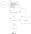
- tubes are allocated using a procedure such as illustrated in Figure 2 .
- the procedure would begin by taking a first unallocated tube and adding it to a queue for a machine that could perform the greatest number of tests for that tube 201.
- the step may be performed by taking one of the hundred tubes with contents upon which tests a, b, and c need to be performed, and adding it to a queue for one of the machines of type M1, since those machines may be capable of performing all of the tests for those tubes.
- a check may be made of whether more tests may be necessary 202.
- the process may be repeated, with the tube being added to a queue 201 for another machine which was capable of performing one or more of the tests which wouldn't be taken care of by the machines for which the tube was already enqueued (i.e., into whose queues the tube had already been assigned).
- a check may be made to determine if there were more tubes which had not been allocated to machines 203.
- the process could iterate 204 to the next tube (e.g., the second tube from the set of the hundred tubes with contents that needed to be subjected to tests a, b and c) and add that tube to a queue 201 as appropriate. Otherwise, the allocation of tubes to machines could be deemed to be finished, and the physical tubes could be routed between the machines and tested in a manner corresponding to their queue assignments.
- tubes will preferably be assigned to machines in a more sophisticated manner.
- matrices are used.
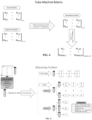
- matrices such as shown in Figure 3 may be used to store information about which tests are required for which tube, and which machines can perform those tests.
- Tube-Test Matrix indicates how the tubes should be allocated to the various machines in the lab.
- an optimization function e.g., the Hungarian algorithm, the auction algorithm, or other algorithm used to solve the assignment problem
- Figure 4 Tube-Machine Matrix
- Other matrix representations are also possible.
- Figure 3 illustrated a Tube-Test Matrix as having one row for each possible combination of tests
- a Tube-Test Matrix may have one row for each tube, so that instead of having 2 n -1 rows where n is the number of tests, a Tube-Test Matrix may have q rows, where q is the number of tubes.
- the Tube-Test, Machine-Test, and Tube-Machine matrices illustrated in Figures 3-4 should be understood as being illustrative only, and should not be treated as limiting.
- FIG. 5 A diagram illustrating how aliquoting may be used to permit parallel operation on material from a single tube is presented in Figure 5 .
- Figure 6 A diagram illustrating how aliquoting may be integrated in an example not part of the present invention into a matrix based optimization workflow such as described above is illustrated in Figure 6 , in which tubes would be aliquoted according to a predefined aliquoting policy, and the Tube-Test Matrix would be used to reflect the tubes as aliquoted, rather than the tubes as originally provided.
- aliquoting of tubes may be determined dynamically, using an alternative workflow such as shown in Figures 8 , 15 , 16 and 17 .
- a check 801 will be performed for whether distributing the tubes in that manner would satisfy various constraints place upon the lab. This could be done, for example, using a process such as shown in Figure 9 , discussed below.
- a mathematical model and heuristics would initially be used to determine the turnaround time for the tubes 901 (e.g., the time necessary for each tube to have the necessary tests performed on its contents could be determined based on the time each of the machines that tube was assigned to would need to perform its testing if operating in isolation under ideal conditions, and based on the assumption that the shortest processing time first heuristic would be used in ordering the tubes to be processed).
- the turnaround times for the tubes could then be checked 902 to confirm that they meet the labs' contractual commitments. If the check 902 indicated that the contractual commitments were met, then turnaround times could be re-determined using a simulation, which could differ from the previous determination 101 based on the use of information about the actual conditions in the lab. In some embodiments, such a simulation may consider factors such as:
- the check 801 for whether constraints are met in a workflow such as shown in Figure 8 may be performed in ways other than via the process of Figure 9 .
- the process of Figure 9 had separate steps for using mathematical models and simulations to determine turnaround time, in some embodiments it is possible that one of those steps could be omitted, and the check 801 of whether constraints are met may be performed using either only a simulation or only a mathematical model.
- factors other than contractually mandated turnaround times could be considered when determining 801 whether constraints are met.
- the checks 902 904 shown in Figure 9 may consider whether whatever level of aliquoting was being proposed would result in the usable amount of a tube's sample material falling below a threshold necessary for the tests (e.g., because of the dead volume in the tubes the sample is aliquoted into), either instead of, or in addition to, considering contractual turnaround time commitments.
- a process such as shown in Figure 9 may be skipped or rendered optional, such as by using a heuristic to determine if aliquoting could potentially make sense (e.g., treating aliquoting as pointless in a case where a deadline associated with a batch of tubes had already expired or in a case where aliquoting would increase the amount of sample lost to dead volume to the extent that it would prevent the necessary tests from being performed), and only proceeding with a process such as shown in Figure 9 if the heuristic indicated that aliquoting had at least some potential benefit.
- a heuristic to determine if aliquoting could potentially make sense (e.g., treating aliquoting as pointless in a case where a deadline associated with a batch of tubes had already expired or in a case where aliquoting would increase the amount of sample lost to dead volume to the extent that it would prevent the necessary tests from being performed), and only proceeding with a process such as shown in Figure 9 if the heuristic indicated that aliquoting had at least some
- the output of a process of Figure 9 may be a simple YES/NO indication of whether the constraints were met.
- the output of a process such as shown in Figure 9 may include more information, such as which tubes a constraint was violated for, and the nature of the violation (e.g., an indication that the turnaround time for a particular tube was too long, because a particular machine that tube was assigned to was likely to become a bottleneck, because that tube had a short turnaround time yet was placed behind another tube in the queue for a machine, or because that machine was located far from the other machines in the lab and so using it would require considering the time to physically transport a tube to the machine).
- the discussion above of the process of Figure 9 should be understood as being illustrative only, and should not be treated as being limiting on the scope of protection provided by this document or any other related document.
- a potential aliquoting and test assignment may be determined 802. This could result in a revised Tube-Test Matrix, which would be used to create a new Tube-Machine Matrix and determine a new sequence and schedule for the tubes to be processed. That new sequence and schedule could be checked 801 to determine if the proposed aliquoting and test assignment would allow the relevant constraints to be met. This could then be repeated one or more times, potentially with a different aliquoting and test assignment being determined 802 each time.
- an initial aliquoting and test assignment could be generated using a relatively conservative aliquoting policy (i.e., one which results in a relatively small increase in the number of tubes used to hold the samples), with a more aggressive policy being used on each subsequent iteration until ultimately a schedule and sequence for the tubes which met the relevant constraints had been created.
- a relatively conservative aliquoting policy i.e., one which results in a relatively small increase in the number of tubes used to hold the samples
- a more aggressive policy being used on each subsequent iteration until ultimately a schedule and sequence for the tubes which met the relevant constraints had been created.
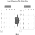
- the workflow shown in Figure 8 may be deemed complete, and the tubes could be physically aliquoted and tested in the manner which had resulted in the constraints being met. Examples of results which could be obtained from applying different types of aliquoting policies in this type of progression, and their respective impacts on the number of tubes and the Tube-Machine Matrix, are illustrated in Figures 11-13 .
- this type of variation consider the step of determining an aliquoting and test assignment 802. As discussed above, in some cases, this determination may be made by applying an aliquoting policy wholesale to a set of tubes which were to be processed by a lab. However, it is also possible that, in some embodiments, this type of determination 802 could be performed in a more targeted manner, such as by only aliquoting those tubes which caused a constraint not to be met.
- the tubes allocated to a particular machine by the previous tube-machine matrix had caused a turnaround time requirement to be violated, then initially only those tubes could be aliquoted, rather than aliquoting all tubes to be processed.
- aliquoting might be limited to only those tubes which violated the turnaround time constraint.
- this type of conditional focusing could also be applied to cases where turnaround time is defined on a per-test basis, with aliquoting applied to only those tubes whose contents required a test which violated the turnaround time constraint.
- Additional levels of targeting may also possible in some embodiments. For example, in some embodiments it is possible that tubes which violate a turnaround time constraint could be treated as only candidates for aliquoting, and would only be aliquoted and given a new test assignment if they passed one or more additional filters. In some embodiments, in cases where candidate tubes are aliquoted only after passing through one or more exclusion filters, there may be a variety of exclusion filters which could potentially be applied. For example, in some embodiments, only candidate tubes with certain priority designations (e.g., Stat) or from certain sources (e.g., a hospital) may be aliquoted, while other candidate tubes may be excluded unless there were no candidate tubes with a priority designation or from a prioritized source to consider.
- priority designations e.g., Stat
- sources e.g., a hospital
- a check may be made to ensure that aliquoting could potentially solve (or at least improve on) the problem that caused a tube to be a candidate and, if it did not, then that tube would be excluded.
- T Q is the timing due to the tube's current (i.e., without aliquoting) position in the instrument queues
- T T is the timing due to transporting the tube between machines
- T A is the time necessary to aliquot the tube
- T L is the longest time any of the aliquoted tubes would be in queue based on the current aliquoting
- T R is the turnaround time requirement for the tube.
- similar types of exclusion may also be performed for turnaround times which are defined on a per-test rather than per-tube basis (e.g., a candidate tube could be excluded from aliquoting if at least one of the tests that would need to be performed for that tube had a turnaround time constraint which could not be met based on the existing queue for the machine which would perform that test), or for characteristics other than turnaround time (e.g., a candidate tube could be excluded if there would not be enough sample to perform the necessary tests once the dead volumes of the tubes the sample would be aliquoted into were considered). Accordingly, the above discussion of excluding candidate tubes from actually being aliquoted should be understood as being illustrative only, and should not be treated as limiting.
- Variations in how the step of determining an aliquoting and test assignment 802 beyond determining what tubes to aliquot may also be possible in some embodiments.
- this may be done by simply determining the maximum number of aliquots and then aliquoting a sample based on that number or the number of required tests (e.g., determine the maximum number of tubes a sample could be aliquoted into considering dead volume, and then aliquot the sample into either that maximum number of tubes, or a number of tubes equal to the number of tests required for the tube prior to aliquoting, whichever is less).
- a tube in a case where a tube is subject to a turnaround time constraint which is defined on a per-tube basis, then if that tube is to be aliquoted (e.g., if it was identified as an aliquoting candidate and satisfied any applicable exclusion criteria, in an implementation where the candidate-exclusion approach is used) it could be aliquoted into a number of tubes based on the number of machines necessary to do the tests on the tube's contents.
- a tube is subject to a turnaround time constraint which is defined on a per-test basis, then if that tube is to be aliquoted it may be aliquoted to a number of tubes which is equal to the number of machines which could potentially perform the test for which a turnaround time constraint was not met.
- other variations such as combined approaches (e.g., using maximum number of aliquots based on dead volume as a ceiling in a case where the number of aliquots would otherwise be determined based on turnaround time constraints), may also be possible, and may be implemented without undue experimentation by those of ordinary skill in the art in light of this disclosure. Accordingly, the preceding description of variations in numbers of aliquots, like the description of variations in targeting of aliquots, should be understood as being illustrative only, and should not be treated as limiting.
- KPIs key performance indicators
- KPIs may be things such as number of tubes not fulfilling turnaround time constraints, percent of tubes not fulfilling turnaround time constraints, or more high level considerations like overall lab throughput or overall sum of the delay between when tubes (or tube tests) are actually done relative to the deadlines for those tubes (or tube tests).
- a computer may repeat the workflow of Figure 2 for that batch of tubes at least once, and may continue to repeat the workflow until the KPIs stopped improving, at which point the aliquoting and test assignment which had been found to have the best impact on the KPIs may be declared optimal, and the tubes could be aliquoted and dispatched to machines based on that assignment.
- the use of KPIs may not require new aliquoting and test assignments to be created until such time as an optimal assignment had been identified.
- KPIs may simply be compared to thresholds (e.g., no more than 5% of tubes failing to meet turnaround time requirements), and the workflow may be repeated until either the thresholds were met or the KPIs ceased improving.
- thresholds e.g., no more than 5% of tubes failing to meet turnaround time requirements
- a user may be requested to make a determination of which of the acceptable solutions would be used.
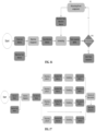
- Figures 16 and 17 Additional examples of workflows which may be used in some embodiments to dynamically determine whether and/or how aliquoting should be performed are provided in Figures 16 and 17 .
- a process is shown which is similar to the processes of Figures 8 and 15 in that it may iteratively repeat the determination of an aliquoting and test assignment 802 until a final aliquoting and test assignment is identified.
- the process of Figure 16 differs from those shown in Figures 8 and 15 in that the process of Figure 16 may repeat a much smaller portion of the overall workflow on each iteration - reusing the machine assignments for the new aliquots rather than recomputing the tube-machine matrix for each potential aliquoting and test assignment determination 802.
- Figures 8 , 15 and 16 illustrated workflows which would iteratively determine aliquoting and test assignments 802, this iterative determination would not necessarily be present in all cases where the disclosed technology is used to implement dynamic aliquoting.
- An example of how the dynamic determination of aliquoting could be performed in some embodiments without iteration such as shown in Figures 8 , 15 and 16 is provided in Figure 17 , in which multiple aliquoting policies may be applied in parallel (e.g., as different threads in a multi-threaded process, as different processes launched on a single system, etc.), and then the results of those policies maybe compared with each other to determine which was most suitable for a given situation.
- Table 1 Illustrative Tube-Machine Matrix Analyzer A Analyzer B Tube 1 2/15 7/30 Tube 2 3/14 5/22 Tube 3 5/20 4/5 Tube 4 6/11 5/11 Tube 5 3/4 3/23
- the entries for each tube indicate both the time necessary for that tube to be processed by a particular analyzer, and the deadline for the processing of that tube by the analyzer to be complete.
- the operation of Analyzer A on Tube 1 takes two time units, and the due date for the processing of Tube 1 by Analyzer A is 15 time units.
- the sequence of the tubes on the analyzer would preferably be determined in a way to minimize the number of delayed operations.
- an earliest due date priority rule can be applied, and in the case of a tie, a shortest processing time rule may be employed to sequence tubes on the analyzers.
- a Gantt chart showing a schedule of un-aliquoted tubes created using this approach is provided in Figure 7 .
- the due date for the processing of Tube 4 on Analyzer B i.e., 11 time units
- the due date for the processing of Tube 4 on Analyzer B i.e., 11 time units
- FIG. 10 is a revised Gantt chart in which Tube 4 is replaced by tubes T4*I and T4*II, representing the tubes into which Tube 4 had been aliquoted.
- Figure 10 shows that with this aliquoting, all of the due dates for the tubes are met, and so there is no delayed operation, thereby illustrating the usefulness of the disclosed technology to comply with requirements related to processing for tubes while still avoiding the costs associated with aliquoting more tubes than are necessary.
- FIG. 14 that figure illustrates a computer system such as could be used to perform generation of aliquoting instructions and machine assignments in some embodiments.
- a computer system may include one or more processors 1401, one more computer readable memories 1402 (e.g., RAM, ROM or various other types of storage), a communication bus 1403, and one or more external device interfaces 1404 1405 (e.g., USB ports, parallel ports, TCP/IP adapter cards, etc.).
- external device interfaces 1404 1405 may be connected to various input devices 1406 (e.g., keyboards, touch screen interfaces, etc.) and/or various laboratory machines such as aliquoters 1407.
- instructions for performing workflows such as described herein may be stored in the one or more computer readable memories 1402, and those instructions may be executed by a processor 1401 on input received from an external input device 1406 to generate aliquoting instructions which may be sent to an aliquoter 1407 to specify how tubes should be aliquoted.
- machine assignments may also be generated and sent to analytic machines which would actually process the aliquoted tubes (not shows in figure 14 ) so that in some embodiments an entire laboratory may potentially be controlled in an optimized manner as described herein.
- patient refers to a human or non-human subject who is being tested, treated, monitored or the like for a medical condition, disease or the like by a custodian.
- machine refers to a device or combination of devices.
- network refers to any collection of networks using standard protocols.
- the term includes a collection of interconnected (public and/or private) networks that are linked together by a set of standard protocols (such as TCP/IP, HTTP, etc.) to form a global, distributed network.
- standard protocols such as TCP/IP, HTTP, etc.
- the term is also intended to encompass variations that may be made in the future, including changes and additions to existing standard protocols or integration with other media (e.g., television, radio, etc.).
- sample refers to any biological sample
- biological sample is meant to cover any specimen of biological material which has been isolated from its natural environment, such as the body of an animal or a human being. It can be in solid form such as tissues, bones, ligaments, and the like. It can also be in liquid form such as blood, spinal fluid, and the like.
- set refers to a number, group, or combination of zero or more things of similar nature, design, or function.
- the term "based on” means that something is determined at least in part by the thing that it is indicated as being “based on.” To indicate that something must be completely determined based on something else, it would be described as being based “exclusively” on whatever it is completely determined by.
- modifiers such as “first,” “second,” and so forth are simply labels used to improve readability, and are not intended to imply any temporal or substantive difference between the items they modify. For example, referring to items as a “first program” and a “second program” in the claims should not be understood to indicate that the “first program” is created first, or that the two programs would necessarily cause different things to happen when executed by a computer.
Landscapes
- Health & Medical Sciences (AREA)
- Engineering & Computer Science (AREA)
- General Health & Medical Sciences (AREA)
- Public Health (AREA)
- Medical Informatics (AREA)
- Biomedical Technology (AREA)
- Epidemiology (AREA)
- Primary Health Care (AREA)
- Pathology (AREA)
- Chemical & Material Sciences (AREA)
- Analytical Chemistry (AREA)
- Immunology (AREA)
- General Business, Economics & Management (AREA)
- Physics & Mathematics (AREA)
- Life Sciences & Earth Sciences (AREA)
- Business, Economics & Management (AREA)
- General Physics & Mathematics (AREA)
- Biochemistry (AREA)
- Data Mining & Analysis (AREA)
- Databases & Information Systems (AREA)
- Automatic Analysis And Handling Materials Therefor (AREA)
- Medical Treatment And Welfare Office Work (AREA)
- Investigating Or Analysing Biological Materials (AREA)
Claims (9)
- Maschine, umfassend:a) eine Vielzahl von Laborinstrumenten, wobei jedes Laborinstrument zur Durchführung mindestens eines Tests angepasst ist;b) mindestens ein Aliquoter (1407);
undc) mindestens ein System, das einen Speicher (1402) und einen Prozessor (1401) umfasst, wobei das System mit Anweisungen konfiguriert ist, die so angepasst sind, dass sie bewirken, dass das System, wenn es ausgeführt wird, die Schritte durchführt, die Folgendes umfassen:i) Bestimmen einer oder mehrerer Methoden, um Proben, die in einer Vielzahl von Röhrchen enthalten sind, in zusätzliche Röhrchen zu trennen;ii) Bestimmen eines oder mehrerer Ergebnisse, die der einen oder den mehreren Methoden zum Trennen der Proben entsprechen,iii) Auswerten des einen oder der mehreren Ergebnisse, die der einen oder den mehreren Methoden zum Trennen der Proben entsprechen,iv) Genehmigen einer der einen oder mehreren Methoden zum Trennen der Proben auf der Grundlage der Auswertung des einen oder der mehreren Ergebnisse, die der einen oder den mehreren Methoden zum Trennen der Proben entsprechen, undv) Trennen der in der Vielzahl von Röhrchen enthaltenen Proben mit der genehmigten Methode unter Verwendung des mindestens einen Aliquoters,wobei das Bestimmen des einen oder der mehreren Ergebnisse, die der einen oder den mehreren Methoden zum Trennen der Proben entsprechen, für jede der einen oder mehreren Methoden zum Trennen der Proben auf Folgendem basiert:a) einer ersten Matrix, die angibt, welche Tests für welche Röhrchen erforderlich sind, einschließlich, welche Tests für die zusätzlichen Röhrchen erforderlich sind, undb) einer zweiten Matrix, die die Arten von Tests angibt, für deren Durchführung die Laborinstrumente aus der Vielzahl von Laborinstrumenten angepasst sind,wobei das Bestimmen des einen oder der mehreren Ergebnisse, die einer oder mehreren Methoden zum Trennen der Proben entsprechen, für jede eine oder mehrere Methoden zum Trennen der Proben umfasst:Eingeben der ersten Matrix und der zweiten Matrix in eine Optimierungsfunktion, um eine dritte Matrix zu erstellen, die angibt, wie die Röhrchen den Laborinstrumenten zugewiesen werden sollten, undBestimmen einer Reihenfolge und eines Zeitplans für die Verteilung der Röhrchen an die Laborinstrumente basierend auf der dritten Matrix,wobei die Ergebnisse basierend auf der Reihenfolge und/oder dem Zeitplan ausgewertet werden. - Maschine nach Anspruch 1, wobei die Schritte, zu deren Durchführung die Anweisungen das System veranlassen, wenn es ausgeführt wird, Folgendes umfassen:a) Bestimmen einer anfänglichen Methode, die in die Vielzahl von Röhrchen enthaltenen Proben in zusätzliche Röhrchen zu trennen;b) Bestimmen eines anfänglichen Ergebnisses, das der anfänglichen Methode entspricht, die in der Vielzahl von Röhrchen enthaltenen Proben in zusätzliche Röhrchen zu trennen;c) Bestimmen, ob die anfängliche Methode zum Trennen der in der Vielzahl von Röhrchen enthaltenen Proben in zusätzliche Röhrchen auf der Grundlage der Auswertung des anfänglichen Ergebnisses genehmigt werden soll;d) bis eine Methode zum Trennen der in der Vielzahl von Röhrchen enthaltenen Proben in zusätzliche Röhrchen genehmigt ist, Wiederholen der folgenden Schritte:i) Bestimmen einer neuen Methode zum Trennen der in der Vielzahl von Röhrchen enthaltenen Proben in zusätzliche Röhrchen, wobei die neue Methode zum Trennen der in der Vielzahl von Röhrchen enthaltenen Proben in zusätzliche Röhrchen die Anzahl der zusätzlichen Röhrchen, in die die Proben getrennt werden, im Vergleich zu einer neuesten zuvor bestimmten Methode zum Trennen der in der Vielzahl von Röhrchen enthaltenen Proben in zusätzliche Röhrchen erhöht;ii) Bestimmen eines neuen Ergebnisses, das der neuen Methode zum Trennen der in der Vielzahl von Röhrchen enthaltenen Proben in zusätzliche Röhrchen entspricht; undiii) Bestimmen, ob die neue Methode zum Trennen der in der Vielzahl von zusätzlichen Röhrchen enthaltenen Proben auf der Grundlage der Auswertung des neuen Ergebnisses genehmigt werden soll.
- Maschine nach Anspruch 1, wobei das System mit einer Vielzahl von Aliquotierungsrichtlinien konfiguriert ist und so konfiguriert ist, dass es eine oder mehrere Methoden bestimmt, die in der Vielzahl von Röhrchen enthaltenen Proben parallel für jede der Aliquotierungsrichtlinien in zusätzliche Röhrchen zu trennen.
- Maschine nach Anspruch 1, wobei die Auswertung der Ergebnisse, die der einen oder den mehreren Methoden zum Trennen der Proben entsprechen, das Bestimmen der Auswirkung der Ergebnisse auf mindestens einen Hauptleistungsindikator umfasst.
- Maschine nach Anspruch 1, wobei:a) Auswerten der Ergebnisse, die der einen oder den mehreren Methoden zum Trennen der Proben entsprechen, das Bestimmen umfasst, ob jedes der ausgewerteten Ergebnisse dem Erfüllen einer Anforderung zum Verarbeiten der Proben entspricht; undb) die Anweisungen so angepasst sind, dass sie bewirken, dass das System eine der einen oder mehreren Methoden zum Trennen der in der Vielzahl von Röhrchen enthaltenen Proben in zusätzliche Röhrchen genehmigt, selbst wenn keines der ausgewerteten Ergebnisse die Anforderungen für die Verarbeitung der Proben erfüllt.
- Maschine nach Anspruch 1, wobei das System eine virtuelle Maschine entfernt von der Vielzahl von Laborinstrumenten und dem mindestens einen Aliquoter hostet.
- Verfahren, umfassend:i) Bestimmen einer oder mehrerer Methoden, um Proben, die in einer Vielzahl von Röhrchen enthalten sind, in zusätzliche Röhrchen zu trennen;ii) Bestimmen eines oder mehrerer Ergebnisse, die der einen oder den mehreren Methoden zum Trennen der Proben entsprechen,iii) Auswerten des einen oder der mehreren Ergebnisse, die der einen oder den mehreren Methoden zum Trennen der Proben entsprechen,iv) Genehmigen einer der einen oder mehreren Methoden zum Trennen der Proben auf der Grundlage der Auswertung des einen oder der mehrerer Ergebnisse, die der einen oder den mehreren Methoden zum Trennen der Proben entsprechen, undv) Trennen der in der Vielzahl von Röhrchen enthaltenen Proben mit der genehmigten Methode unter Verwendung mindestens eines Aliquoters,wobei das Bestimmen des einen oder der mehreren Ergebnisse, die der einen oder den mehreren Methoden zum Trennen der Proben entsprechen, für jede der einen oder mehreren Methoden zum Trennen der Proben auf Folgendem basiert:a) einer ersten Matrix, die angibt, welche Tests für welche Röhrchen erforderlich sind, einschließlich, welche Tests für die zusätzlichen Röhrchen erforderlich sind, undb) einer zweiten Matrix, die die Arten von Tests angibt, für deren Durchführung Laborinstrumente angepasst sind, wobei jedes Laborinstrument für die Durchführung mindestens eines Tests angepasst ist,wobei das Bestimmen des einen oder der mehreren Ergebnisse, die einer oder mehreren Methoden zum Trennen der Proben entsprechen, für jede eine oder mehrere Methoden zum Trennen der Proben umfasst:Eingeben der ersten Matrix und der zweiten Matrix in eine Optimierungsfunktion, um eine dritte Matrix zu erstellen, die angibt, wie die Röhrchen den Laborinstrumenten zugewiesen werden sollten, undBestimmen einer Reihenfolge und eines Zeitplans für die Verteilung der Röhrchen an die Laborinstrumente basierend auf der dritten Matrix,wobei die Ergebnisse basierend auf der Reihenfolge und/oder dem Zeitplan ausgewertet werden.
- Verfahren nach Anspruch 7,
wobei das Verfahren umfasst:1) Ausführen des Schritts (i) für eine mögliche Methode zum Trennen der Proben,2) Ausführen der Schritte (ii) und (iii) für die mögliche Methode, die Proben zu trennen,3) Wiederholen der Schritte (1) - (2), bis in Schritt iv) eine Methode zum Trennen der Proben genehmigt wird. - Verfahren nach Anspruch 8, wobei jedes Mal, wenn die Schritte (1) bis (2) von Anspruch 8 durchgeführt werden, die mögliche Methode zum Trennen der in der Vielzahl von Röhrchen enthaltenen Proben in zusätzliche Röhrchen die in der Vielzahl von Röhrchen enthaltenen Proben in mehr zusätzliche Röhrchen trennt als eine neueste zuvor bestimmte Methode zum Trennen der Proben.
Applications Claiming Priority (2)
| Application Number | Priority Date | Filing Date | Title |
|---|---|---|---|
| US201662432930P | 2016-12-12 | 2016-12-12 | |
| PCT/US2017/065345 WO2018111721A1 (en) | 2016-12-12 | 2017-12-08 | Intelligent handling of materials |
Publications (2)
| Publication Number | Publication Date |
|---|---|
| EP3552025A1 EP3552025A1 (de) | 2019-10-16 |
| EP3552025B1 true EP3552025B1 (de) | 2025-02-19 |
Family
ID=60915634
Family Applications (1)
| Application Number | Title | Priority Date | Filing Date |
|---|---|---|---|
| EP17823288.0A Active EP3552025B1 (de) | 2016-12-12 | 2017-12-08 | Intelligente handhabung von materialien |
Country Status (7)
| Country | Link |
|---|---|
| US (1) | US11549958B2 (de) |
| EP (1) | EP3552025B1 (de) |
| JP (1) | JP2020512534A (de) |
| CN (1) | CN110192111B (de) |
| AU (1) | AU2017378068A1 (de) |
| CA (1) | CA3046815A1 (de) |
| WO (1) | WO2018111721A1 (de) |
Families Citing this family (3)
| Publication number | Priority date | Publication date | Assignee | Title |
|---|---|---|---|---|
| EP3633510A1 (de) * | 2018-10-01 | 2020-04-08 | Siemens Aktiengesellschaft | System, vorrichtung und verfahren zum betrieb einer laborautomatisierungsumgebung |
| EP3757575B1 (de) * | 2019-06-24 | 2023-06-07 | F. Hoffmann-La Roche AG | Verfahren zum betrieb eines analyselabors |
| CN112881703B (zh) * | 2019-11-30 | 2024-04-19 | 深圳市帝迈生物技术有限公司 | 一种血液检测装置及方法、计算机存储介质 |
Family Cites Families (15)
| Publication number | Priority date | Publication date | Assignee | Title |
|---|---|---|---|---|
| GB9810574D0 (en) * | 1998-05-18 | 1998-07-15 | Thermo Bio Analysis Corp | Apparatus and method for monitoring and controlling laboratory information and/or instruments |
| US6581012B1 (en) * | 1999-07-30 | 2003-06-17 | Coulter International Corp. | Automated laboratory software architecture |
| ES2333697T3 (es) * | 2001-04-05 | 2010-02-26 | Inpeco Ip Ltd. | Metodo para la gestion de sistemas de celula de trabajo basado en un sistema de gestion de la automatizacion. |
| JP2003315348A (ja) * | 2002-04-22 | 2003-11-06 | Hitachi High-Technologies Corp | 検体処理システム及びそれを用いた検体検査自動化システム |
| US7860727B2 (en) * | 2003-07-17 | 2010-12-28 | Ventana Medical Systems, Inc. | Laboratory instrumentation information management and control network |
| US20080235055A1 (en) * | 2003-07-17 | 2008-09-25 | Scott Mattingly | Laboratory instrumentation information management and control network |
| US6984527B2 (en) * | 2003-08-11 | 2006-01-10 | Dade Behring Inc. | Automated quality control protocols in a multi-analyzer system |
| US20060095484A1 (en) | 2004-10-28 | 2006-05-04 | Netaps Inc. | Method and system for solving an optimization problem |
| US20070282476A1 (en) * | 2006-06-06 | 2007-12-06 | Siemens Corporate Research, Inc | Dynamic Workflow Scheduling |
| US8112229B2 (en) * | 2007-05-31 | 2012-02-07 | Abbott Laboratories | Method for determining the order of execution of assays of a sample in a laboratory automation system |
| EP2450711A1 (de) * | 2010-11-03 | 2012-05-09 | F. Hoffmann-La Roche AG | Analysesystem zur Analyse biologischer Proben |
| ES2490965T3 (es) | 2011-04-29 | 2014-09-04 | F. Hoffmann-La Roche Ag | Procedimiento para la operación de una celda de trabajo para muestras automatizadas |
| WO2013129191A1 (ja) * | 2012-02-27 | 2013-09-06 | 株式会社日立ハイテクノロジーズ | 検体前処理システム |
| WO2015126839A1 (en) * | 2014-02-19 | 2015-08-27 | Siemens Healthcare Diagnostics Inc. | Mother daughter tube carrier for aliquoters |
| EP3410323B1 (de) * | 2017-05-29 | 2020-11-25 | F. Hoffmann-La Roche AG | Verfahren zum betrieb eines laborsystems |
-
2017
- 2017-12-08 CN CN201780083174.0A patent/CN110192111B/zh active Active
- 2017-12-08 WO PCT/US2017/065345 patent/WO2018111721A1/en not_active Ceased
- 2017-12-08 EP EP17823288.0A patent/EP3552025B1/de active Active
- 2017-12-08 JP JP2019531317A patent/JP2020512534A/ja active Pending
- 2017-12-08 US US16/468,430 patent/US11549958B2/en active Active
- 2017-12-08 CA CA3046815A patent/CA3046815A1/en not_active Abandoned
- 2017-12-08 AU AU2017378068A patent/AU2017378068A1/en not_active Abandoned
Also Published As
| Publication number | Publication date |
|---|---|
| CN110192111A (zh) | 2019-08-30 |
| US20210072268A1 (en) | 2021-03-11 |
| JP2020512534A (ja) | 2020-04-23 |
| CN110192111B (zh) | 2024-07-02 |
| CA3046815A1 (en) | 2018-06-21 |
| US11549958B2 (en) | 2023-01-10 |
| WO2018111721A1 (en) | 2018-06-21 |
| EP3552025A1 (de) | 2019-10-16 |
| AU2017378068A1 (en) | 2019-07-04 |
Similar Documents
| Publication | Publication Date | Title |
|---|---|---|
| Schultz | Fast aircraft turnaround enabled by reliable passenger boarding | |
| CN111213124B (zh) | 在乱序处理器中完成合并的全局完成表条目 | |
| WO2010050926A1 (en) | Workforce planning | |
| Santini | Optimising the assignment of swabs and reagent for PCR testing during a viral epidemic | |
| US11549958B2 (en) | Intelligent handling of materials | |
| Yang et al. | A model to create an efficient and equitable admission policy for patients arriving to the cardiothoracic ICU | |
| Pongjetanapong et al. | Implementing complex task allocation in a cytology lab via HCCM using Flexsim HC | |
| WO2020106696A1 (en) | Scheduling tests in a laboratory environment | |
| JP5378962B2 (ja) | 動的搬送計画装置及び動的搬送計画方法 | |
| Haque | Design and Simulation of Sustainable Calibration Systems for Future Industrial Engineering Applications | |
| Kiani et al. | Evaluating appointment postponement in scheduling patients at a diagnostic clinic | |
| Kohútka et al. | A new FPGA-based task scheduler for real-time systems | |
| El Kawam et al. | Decoding Eastern European national public-private partnership infrastructure programs | |
| Leusder et al. | Patient-level cost analysis of subfertility pathways in the Dutch healthcare system | |
| Leeftink et al. | Batch scheduling in the histopathology laboratory | |
| Nickel et al. | Process improvement in hospitals: a case study in a radiology department | |
| Leeftink et al. | Predicting turnaround time reductions of the diagnostic track in the histopathology laboratory using mathematical modelling | |
| Sharaki et al. | Self assessment of pre, intra and post analytical errors of urine analysis in Clinical Chemistry Laboratory of Alexandria Main University Hospital | |
| Van Merode et al. | Decision support for clinical laboratory capacity planning | |
| US20250095859A1 (en) | Patient-centric load planning system and method | |
| Bruno et al. | Workflow improvement and financial gain after integration of high-throughput sample processing system with flow cytometer in a high-volume pathology laboratory: Results from a prospective comparative study using Lean principles | |
| Perrotta et al. | Workflow Mapping—A Q-Probes Study of Preanalytic Testing Processes: A College of American Pathologists Q-Probes Study of 35 Clinical Laboratories | |
| Chakhlevitch et al. | Scheduling reentrant jobs on parallel machines with a remote server | |
| Karnchanaphiboonwong et al. | Innovation, automation and informatics improves quality in Lerdsin Hospital, Thailand | |
| Liu et al. | Physician scheduling in case managers style emergency departments: machine learning-aided solution approaches |
Legal Events
| Date | Code | Title | Description |
|---|---|---|---|
| STAA | Information on the status of an ep patent application or granted ep patent |
Free format text: STATUS: UNKNOWN |
|
| STAA | Information on the status of an ep patent application or granted ep patent |
Free format text: STATUS: THE INTERNATIONAL PUBLICATION HAS BEEN MADE |
|
| PUAI | Public reference made under article 153(3) epc to a published international application that has entered the european phase |
Free format text: ORIGINAL CODE: 0009012 |
|
| STAA | Information on the status of an ep patent application or granted ep patent |
Free format text: STATUS: REQUEST FOR EXAMINATION WAS MADE |
|
| 17P | Request for examination filed |
Effective date: 20190703 |
|
| AK | Designated contracting states |
Kind code of ref document: A1 Designated state(s): AL AT BE BG CH CY CZ DE DK EE ES FI FR GB GR HR HU IE IS IT LI LT LU LV MC MK MT NL NO PL PT RO RS SE SI SK SM TR |
|
| AX | Request for extension of the european patent |
Extension state: BA ME |
|
| RIN1 | Information on inventor provided before grant (corrected) |
Inventor name: VARLET, ERIC Inventor name: TALBI, PR. EL GHAZALI Inventor name: BUE, MARTIN Inventor name: FARAMARZI OGHANI, SOHRAB |
|
| DAV | Request for validation of the european patent (deleted) | ||
| DAX | Request for extension of the european patent (deleted) | ||
| STAA | Information on the status of an ep patent application or granted ep patent |
Free format text: STATUS: EXAMINATION IS IN PROGRESS |
|
| 17Q | First examination report despatched |
Effective date: 20210804 |
|
| P01 | Opt-out of the competence of the unified patent court (upc) registered |
Effective date: 20230529 |
|
| GRAP | Despatch of communication of intention to grant a patent |
Free format text: ORIGINAL CODE: EPIDOSNIGR1 |
|
| STAA | Information on the status of an ep patent application or granted ep patent |
Free format text: STATUS: GRANT OF PATENT IS INTENDED |
|
| INTG | Intention to grant announced |
Effective date: 20240419 |
|
| GRAJ | Information related to disapproval of communication of intention to grant by the applicant or resumption of examination proceedings by the epo deleted |
Free format text: ORIGINAL CODE: EPIDOSDIGR1 |
|
| STAA | Information on the status of an ep patent application or granted ep patent |
Free format text: STATUS: EXAMINATION IS IN PROGRESS |
|
| INTC | Intention to grant announced (deleted) | ||
| GRAP | Despatch of communication of intention to grant a patent |
Free format text: ORIGINAL CODE: EPIDOSNIGR1 |
|
| STAA | Information on the status of an ep patent application or granted ep patent |
Free format text: STATUS: GRANT OF PATENT IS INTENDED |
|
| INTG | Intention to grant announced |
Effective date: 20240919 |
|
| GRAS | Grant fee paid |
Free format text: ORIGINAL CODE: EPIDOSNIGR3 |
|
| GRAA | (expected) grant |
Free format text: ORIGINAL CODE: 0009210 |
|
| STAA | Information on the status of an ep patent application or granted ep patent |
Free format text: STATUS: THE PATENT HAS BEEN GRANTED |
|
| AK | Designated contracting states |
Kind code of ref document: B1 Designated state(s): AL AT BE BG CH CY CZ DE DK EE ES FI FR GB GR HR HU IE IS IT LI LT LU LV MC MK MT NL NO PL PT RO RS SE SI SK SM TR |
|
| REG | Reference to a national code |
Ref country code: GB Ref legal event code: FG4D |
|
| REG | Reference to a national code |
Ref country code: CH Ref legal event code: EP |
|
| REG | Reference to a national code |
Ref country code: IE Ref legal event code: FG4D |
|
| REG | Reference to a national code |
Ref country code: DE Ref legal event code: R096 Ref document number: 602017087890 Country of ref document: DE |
|
| REG | Reference to a national code |
Ref country code: NL Ref legal event code: MP Effective date: 20250219 |
|
| PG25 | Lapsed in a contracting state [announced via postgrant information from national office to epo] |
Ref country code: RS Free format text: LAPSE BECAUSE OF FAILURE TO SUBMIT A TRANSLATION OF THE DESCRIPTION OR TO PAY THE FEE WITHIN THE PRESCRIBED TIME-LIMIT Effective date: 20250519 |
|
| PG25 | Lapsed in a contracting state [announced via postgrant information from national office to epo] |
Ref country code: FI Free format text: LAPSE BECAUSE OF FAILURE TO SUBMIT A TRANSLATION OF THE DESCRIPTION OR TO PAY THE FEE WITHIN THE PRESCRIBED TIME-LIMIT Effective date: 20250219 |
|
| PG25 | Lapsed in a contracting state [announced via postgrant information from national office to epo] |
Ref country code: PL Free format text: LAPSE BECAUSE OF FAILURE TO SUBMIT A TRANSLATION OF THE DESCRIPTION OR TO PAY THE FEE WITHIN THE PRESCRIBED TIME-LIMIT Effective date: 20250219 |
|
| PG25 | Lapsed in a contracting state [announced via postgrant information from national office to epo] |
Ref country code: ES Free format text: LAPSE BECAUSE OF FAILURE TO SUBMIT A TRANSLATION OF THE DESCRIPTION OR TO PAY THE FEE WITHIN THE PRESCRIBED TIME-LIMIT Effective date: 20250219 |
|
| REG | Reference to a national code |
Ref country code: LT Ref legal event code: MG9D |
|
| PG25 | Lapsed in a contracting state [announced via postgrant information from national office to epo] |
Ref country code: IS Free format text: LAPSE BECAUSE OF FAILURE TO SUBMIT A TRANSLATION OF THE DESCRIPTION OR TO PAY THE FEE WITHIN THE PRESCRIBED TIME-LIMIT Effective date: 20250619 Ref country code: NO Free format text: LAPSE BECAUSE OF FAILURE TO SUBMIT A TRANSLATION OF THE DESCRIPTION OR TO PAY THE FEE WITHIN THE PRESCRIBED TIME-LIMIT Effective date: 20250519 |
|
| PG25 | Lapsed in a contracting state [announced via postgrant information from national office to epo] |
Ref country code: NL Free format text: LAPSE BECAUSE OF FAILURE TO SUBMIT A TRANSLATION OF THE DESCRIPTION OR TO PAY THE FEE WITHIN THE PRESCRIBED TIME-LIMIT Effective date: 20250219 |
|
| PG25 | Lapsed in a contracting state [announced via postgrant information from national office to epo] |
Ref country code: HR Free format text: LAPSE BECAUSE OF FAILURE TO SUBMIT A TRANSLATION OF THE DESCRIPTION OR TO PAY THE FEE WITHIN THE PRESCRIBED TIME-LIMIT Effective date: 20250219 |
|
| PG25 | Lapsed in a contracting state [announced via postgrant information from national office to epo] |
Ref country code: LV Free format text: LAPSE BECAUSE OF FAILURE TO SUBMIT A TRANSLATION OF THE DESCRIPTION OR TO PAY THE FEE WITHIN THE PRESCRIBED TIME-LIMIT Effective date: 20250219 Ref country code: PT Free format text: LAPSE BECAUSE OF FAILURE TO SUBMIT A TRANSLATION OF THE DESCRIPTION OR TO PAY THE FEE WITHIN THE PRESCRIBED TIME-LIMIT Effective date: 20250620 |
|
| PG25 | Lapsed in a contracting state [announced via postgrant information from national office to epo] |
Ref country code: GR Free format text: LAPSE BECAUSE OF FAILURE TO SUBMIT A TRANSLATION OF THE DESCRIPTION OR TO PAY THE FEE WITHIN THE PRESCRIBED TIME-LIMIT Effective date: 20250520 Ref country code: BG Free format text: LAPSE BECAUSE OF FAILURE TO SUBMIT A TRANSLATION OF THE DESCRIPTION OR TO PAY THE FEE WITHIN THE PRESCRIBED TIME-LIMIT Effective date: 20250219 |
|
| REG | Reference to a national code |
Ref country code: AT Ref legal event code: MK05 Ref document number: 1768730 Country of ref document: AT Kind code of ref document: T Effective date: 20250219 |
|
| PG25 | Lapsed in a contracting state [announced via postgrant information from national office to epo] |
Ref country code: SE Free format text: LAPSE BECAUSE OF FAILURE TO SUBMIT A TRANSLATION OF THE DESCRIPTION OR TO PAY THE FEE WITHIN THE PRESCRIBED TIME-LIMIT Effective date: 20250219 |
|
| PG25 | Lapsed in a contracting state [announced via postgrant information from national office to epo] |
Ref country code: SM Free format text: LAPSE BECAUSE OF FAILURE TO SUBMIT A TRANSLATION OF THE DESCRIPTION OR TO PAY THE FEE WITHIN THE PRESCRIBED TIME-LIMIT Effective date: 20250219 |
|
| PG25 | Lapsed in a contracting state [announced via postgrant information from national office to epo] |
Ref country code: DK Free format text: LAPSE BECAUSE OF FAILURE TO SUBMIT A TRANSLATION OF THE DESCRIPTION OR TO PAY THE FEE WITHIN THE PRESCRIBED TIME-LIMIT Effective date: 20250219 |
|
| PG25 | Lapsed in a contracting state [announced via postgrant information from national office to epo] |
Ref country code: IT Free format text: LAPSE BECAUSE OF FAILURE TO SUBMIT A TRANSLATION OF THE DESCRIPTION OR TO PAY THE FEE WITHIN THE PRESCRIBED TIME-LIMIT Effective date: 20250219 |
|
| PG25 | Lapsed in a contracting state [announced via postgrant information from national office to epo] |
Ref country code: AT Free format text: LAPSE BECAUSE OF FAILURE TO SUBMIT A TRANSLATION OF THE DESCRIPTION OR TO PAY THE FEE WITHIN THE PRESCRIBED TIME-LIMIT Effective date: 20250219 |
|
| PG25 | Lapsed in a contracting state [announced via postgrant information from national office to epo] |
Ref country code: EE Free format text: LAPSE BECAUSE OF FAILURE TO SUBMIT A TRANSLATION OF THE DESCRIPTION OR TO PAY THE FEE WITHIN THE PRESCRIBED TIME-LIMIT Effective date: 20250219 Ref country code: CZ Free format text: LAPSE BECAUSE OF FAILURE TO SUBMIT A TRANSLATION OF THE DESCRIPTION OR TO PAY THE FEE WITHIN THE PRESCRIBED TIME-LIMIT Effective date: 20250219 |
|
| PG25 | Lapsed in a contracting state [announced via postgrant information from national office to epo] |
Ref country code: RO Free format text: LAPSE BECAUSE OF FAILURE TO SUBMIT A TRANSLATION OF THE DESCRIPTION OR TO PAY THE FEE WITHIN THE PRESCRIBED TIME-LIMIT Effective date: 20250219 |
|
| PG25 | Lapsed in a contracting state [announced via postgrant information from national office to epo] |
Ref country code: SK Free format text: LAPSE BECAUSE OF FAILURE TO SUBMIT A TRANSLATION OF THE DESCRIPTION OR TO PAY THE FEE WITHIN THE PRESCRIBED TIME-LIMIT Effective date: 20250219 |
|
| REG | Reference to a national code |
Ref country code: DE Ref legal event code: R097 Ref document number: 602017087890 Country of ref document: DE |
|
| PLBE | No opposition filed within time limit |
Free format text: ORIGINAL CODE: 0009261 |
|
| STAA | Information on the status of an ep patent application or granted ep patent |
Free format text: STATUS: NO OPPOSITION FILED WITHIN TIME LIMIT |
|
| REG | Reference to a national code |
Ref country code: CH Ref legal event code: L10 Free format text: ST27 STATUS EVENT CODE: U-0-0-L10-L00 (AS PROVIDED BY THE NATIONAL OFFICE) Effective date: 20251231 |
|
| PGFP | Annual fee paid to national office [announced via postgrant information from national office to epo] |
Ref country code: GB Payment date: 20251223 Year of fee payment: 9 |
|
| PGFP | Annual fee paid to national office [announced via postgrant information from national office to epo] |
Ref country code: FR Payment date: 20251230 Year of fee payment: 9 |
|
| 26N | No opposition filed |
Effective date: 20251120 |
|
| PGFP | Annual fee paid to national office [announced via postgrant information from national office to epo] |
Ref country code: DE Payment date: 20251229 Year of fee payment: 9 |
|
| PG25 | Lapsed in a contracting state [announced via postgrant information from national office to epo] |
Ref country code: LT Free format text: LAPSE BECAUSE OF FAILURE TO SUBMIT A TRANSLATION OF THE DESCRIPTION OR TO PAY THE FEE WITHIN THE PRESCRIBED TIME-LIMIT Effective date: 20250219 |
|
| PG25 | Lapsed in a contracting state [announced via postgrant information from national office to epo] |
Ref country code: MC Free format text: LAPSE BECAUSE OF FAILURE TO SUBMIT A TRANSLATION OF THE DESCRIPTION OR TO PAY THE FEE WITHIN THE PRESCRIBED TIME-LIMIT Effective date: 20250219 |
|
| REG | Reference to a national code |
Ref country code: CH Ref legal event code: H13 Free format text: ST27 STATUS EVENT CODE: U-0-0-H10-H13 (AS PROVIDED BY THE NATIONAL OFFICE) Effective date: 20260723 |