EP3552015B1 - Système et procédé d'estimation de la température d'un échantillon liquide - Google Patents
Système et procédé d'estimation de la température d'un échantillon liquide Download PDFInfo
- Publication number
- EP3552015B1 EP3552015B1 EP17807848.1A EP17807848A EP3552015B1 EP 3552015 B1 EP3552015 B1 EP 3552015B1 EP 17807848 A EP17807848 A EP 17807848A EP 3552015 B1 EP3552015 B1 EP 3552015B1
- Authority
- EP
- European Patent Office
- Prior art keywords
- sample
- temperature
- measurement chamber
- liquid
- analyte sensor
- Prior art date
- Legal status (The legal status is an assumption and is not a legal conclusion. Google has not performed a legal analysis and makes no representation as to the accuracy of the status listed.)
- Active
Links
Images

Classifications
-
- G—PHYSICS
- G01—MEASURING; TESTING
- G01N—INVESTIGATING OR ANALYSING MATERIALS BY DETERMINING THEIR CHEMICAL OR PHYSICAL PROPERTIES
- G01N27/00—Investigating or analysing materials by the use of electric, electrochemical, or magnetic means
- G01N27/26—Investigating or analysing materials by the use of electric, electrochemical, or magnetic means by investigating electrochemical variables; by using electrolysis or electrophoresis
- G01N27/28—Electrolytic cell components
- G01N27/30—Electrodes, e.g. test electrodes; Half-cells
- G01N27/327—Biochemical electrodes, e.g. electrical or mechanical details for in vitro measurements
- G01N27/3271—Amperometric enzyme electrodes for analytes in body fluids, e.g. glucose in blood
- G01N27/3274—Corrective measures, e.g. error detection, compensation for temperature or hematocrit, calibration
-
- G—PHYSICS
- G01—MEASURING; TESTING
- G01N—INVESTIGATING OR ANALYSING MATERIALS BY DETERMINING THEIR CHEMICAL OR PHYSICAL PROPERTIES
- G01N33/00—Investigating or analysing materials by specific methods not covered by groups G01N1/00 - G01N31/00
- G01N33/48—Biological material, e.g. blood, urine; Haemocytometers
- G01N33/483—Physical analysis of biological material
- G01N33/487—Physical analysis of biological material of liquid biological material
- G01N33/49—Blood
- G01N33/4925—Blood measuring blood gas content, e.g. O2, CO2, HCO3
Definitions
- the present invention relates to a system and method for estimating a temperature of a liquid sample. More particular, the present invention relates to an apparatus and method for estimating a temperature in an apparatus for the analysis of biological liquid samples. A further embodiment, relates to an apparatus and a method for correcting an analyte sensor output based on the estimated temperature. In a yet further embodiment, the disclosure relates to a method of performing a quality control measurement in an apparatus for the analysis of biological liquid samples, in particular a method of performing a quality control measurement in respect of p CO 2 .
- Measurement equipment for medical analytics is designed to measure on biological samples to determine the presence and quantity of certain analytes in the biological sample.
- the measurements are often performed in the course of a diagnostic process before, during, and/or after a treatment of a pathological state of a patient.
- the precision of these measurements is often crucial for the correct diagnosis of the pathological state of the patient, and the reliability of a timely and precise result can be life-critical.
- the reliability and precision of such medical measurement equipment is therefore typically subject to strict quality procedures, which typically impose very rigorous requirements for the laboratory set-up and the conditions to be maintained in the laboratory in order to reliably achieve the required precision.
- the quality and correctness of the measurements obtained is constantly checked using quality control (QC) procedures by measuring on standardized quality control solutions under the same conditions as for actual samples.
- QC quality control
- QC tolerances may be specified by the manufacturer guaranteeing a certain measurement precision, and/or may be subject to regulatory provisions.
- An example for a particularly useful, yet stringent set of regulations, is the guideline for the quality control of laboratory-medical analyses issued by the German association of medical doctors ("shi der fürmaschinechtsch Kunststoff Anlagen Kunststoffen - Rili-B ⁇ K”) as of 25 September 2014.
- Blood analysis devices and apparatus play an important role in medical diagnostics. Obtaining results with the highest possible precision from blood analysis apparatus is therefore of the utmost importance to the users and is a constant quest for the producers of such blood analysis equipment.
- an increasing demand for rapid access to such medical analytics in life-critical situations and at the point of care makes it virtually impossible to comply with requirements that are usually designed for a set-up in a controlled laboratory specialized in medical analytics. Violating the specifications for the set-up may jeopardize the reliability and precision of the results as e.g. required by the above-mentioned quality control regulations, and may, in the worst case, put patient safety at risk.
- One of the environmental parameters to be regarded in this respect is the actual temperature of the apparatus, which is determined by the actual temperature of the room in which the apparatus is located, the potential exposure to localized heating and/or cooling sources, such as incident solar radiation, draft from an open window, or the inappropriate dissipation of heat generated by the operation of the apparatus itself. This may, for example, affect the temperature of the reservoirs of QC-solutions. Furthermore, certain QC-solutions are stored refrigerated prior to use, and the actual temperature upon installation of a new QC-solution pack may therefore deviate from the temperature range that is otherwise required for obtaining QC-measurement results that are compliant with applicable regulations. Installing a new QC-solution reservoir taken directly from the storage cooler may therefore set back the instrument's readiness for measurement until the QC-solution pack has attained the appropriate temperature.
- the QC-procedures involve measuring the QC-solutions under the same conditions as actual samples of body fluids, such as blood. This includes measuring within the same time frame for filling and performing the analysis as for these biological liquid samples. It further includes performing the QC-measurements on the QC-solutions at the same target temperature as for the biological liquid samples.
- the target temperature is in the range between 36°C and 38°C, preferably 37°C, whereas the QC-solution is at temperatures well below the target temperature, such as at the temperature of the room where the apparatus is located, or otherwise at lower temperatures as discussed above.
- a sample of QC solution is prepared for measurement in a measurement chamber by injecting an amount of the relevant QC-solution into the measurement chamber and heating it to the target temperature.
- the resulting short time for heating the sample may pose a challenge to establishing a correct equilibrium of the QC-solution at the target temperature. Determining the initial temperature of the QC-solution upon injection is therefore important to assess the validity of the QC-procedure.
- a user may be required to key in the temperature of the QC-solution used for a QC-measurement, either each time the QC-procedure is performed, or e.g. as a default value.
- a default value e.g. 1
- each QC-solution pack may equip with a temperature reading device, which may further log temperature data, and provide temperature data to a processor unit of the analytic apparatus.
- a temperature reading device which may further log temperature data, and provide temperature data to a processor unit of the analytic apparatus.
- US2014/0273187 A1 discloses a diagnostic test device for in vitro diagnostic testing of blood at the point of care.
- the device comprising fluid handling means, a measurement chamber, with a heater for heating the liquid to be analysed, the heater being controlled by a thermocouple in order to more precisely meet the temperature requirements.
- US 6 114 176 relates to methods and apparatus for measuring the concentration of decomposable substances, such as urea.
- the disclosed methods include adding a gaseous buffer, such as CO 2 , to the solution containing the decomposable compound, measuring the conductivity of the solution, decomposing the decomposable compound, measuring the conductivity of the thus-decomposed compound solution, and calculating the differential conductivities between the two measured solutions.
- the apparatus for carrying out these methods are also disclosed.
- the present invention provides a system and a corresponding method for determining an initial temperature of a liquid injected into a measurement chamber of an apparatus for the analysis of biological liquid samples overcoming at least some of the above-mentioned disadvantages, or to provide an alternative.
- a further embodiment provides a system and/or a corresponding method for assessing the validity of measurements performed in an apparatus for the analysis of biological liquid samples overcoming at least some of the above-mentioned disadvantages, or to provide an alternative.
- a further embodiment provides an improved system and/or a corresponding method for assessing the vallidity of quality control (QC) measurements performed in an apparatus for the analysis of biological liquid samples using calibrated QC-reference liquids.
- QC quality control
- the fluid handling system injects a liquid through the inlet into the measurement chamber at a controlled flow.
- the injected liquid has an initial temperature below a target temperature for liquid samples to be analysed in the measurement chamber.
- the thermostatic sample heater is programmed to control the sample temperature to a target temperature above the temperature of the injected liquid.
- Bioanalytical measurements on body fluids, such as blood, are typically performed at temperatures corresponding to a body temperature.
- the target temperature is therefore typically set to a value between 36°C and 38°C, preferably 37°C, whereas the injected liquid typically has a lower temperature, e.g. the temperature of the surroundings of the apparatus, i.e. room temperature.
- the thermostatic sample heater therefore applies heat in order to warm the injected liquid up to the target temperature.
- the thermostatic sample heater applies heat to the liquid sample upon injection, i.e. immediately or very soon after the liquid sample has entered the measurement chamber through the inlet.
- the thermostatic sample heater is operated during injection, i.e. at the same time as the fluid handling is operated to inject the liquid sample into the measurement chamber, and heat is therefore applied by the thermostatic sample heater to the liquid sample as soon as the liquid sample enters the measurement chamber through the inlet port.
- a rapid conditioning of the liquid sample to the target temperature is achieved, where analysis measurements can be performed. This allows for shortening the measurement cycle and provides the user with fast analysis results on the biological liquid samples to be analysed.
- Corresponding quality control measurements are then also performed under the same conditions and with the same timing, including the timing of the sample heating process.
- the thermostatic sample heater device is operated at least for pre-heating the liquid sample to target temperature prior to starting actual analysis measure ments on the liquid sample.
- Operation of the sample heater as a pre-heater device is particularly advantageous in a set-up where the measurement chamber is encapsulated in a controlled thermal environment, such as a thermostatically controlled housing defining a fixed temperature around the measurement chamber, wherein most preferably the fixed temperature corresponds to the target temperature.
- the processor unit is adapted to receive fluid flow data from the fluid handling system and sample heating data from the sample heater device.
- the processor unit is programmed to retrieve data characterizing the injection flow and the heating applied to the injected liquid, and determines the initial temperature of the injected liquid.
- the sample heater is a thermostatic heater controlling the sample temperature to a fixed target temperature
- the flow and heater data are sufficient to determine the initial temperature.
- an initial temperature value may, for example, be determined using a calibration that has been established beforehand for a given type of apparatus, and/or for each specific apparatus, and which is stored in the processor, e.g. in the form of a formula, such as a polynomial curve or a linear function, or in the form of a look-up table.
- the temperature determination can therefore also be easily retro-fitted to existing bio-analytic apparatus equipped with a fluid handling system for controlling the filling of the measurement chamber and a thermostatic sample heater for controlling the sample temperature to a fixed target temperature.
- a retro-fit may in some cases even be achieved by software update that ensures that the processor unit retrieves the required fluid flow and sample heater data, and contains the required conversion curve for determining the initial temperature based on the fluid flow and sample heater data.
- the initial temperature is determined from a calibration formula as a function of parameters representative of the injection flow and of the heating applied by the thermostatic sample heater to the injected liquid.
- the calibration formula is programmed or tabulated in the processor unit.
- the calibration formula is determined beforehand by calibration of the apparatus by injecting fluid at different known initial temperatures.
- the calibration formula is a polynomial, preferably a linear function.
- the coefficients of the polynomial or linear function may be determined from the calibration data by means of a fitting routine, such as a least-square-fit.
- a calibration formula based on sample flow and heating data may assume remaining parameters or conditions as a constant, which otherwise might enter into the calorimetric considerations.
- the term constant is here to be understood as constant to within significant error limits, i.e. variations of these parameters or conditions are considered as insignificant for the desired/relevant precision of the initial temperature determined, or these parameters/conditions are explicitly or implicitly kept constant for a given calibration.
- the exact calorimetric configuration including e.g. the thermal environment and properties of the measurement chamber, may explicitly or implicitly be included in the calibration formula that has been established beforehand for a given type of apparatus, and/or for each specific apparatus.
- a certain target temperature setting may be explicitly accounted for by choosing a different pre-stored calibration curve depending on the target temperature setting.
- a calibration formula for a given type of apparatus implicitly contains effects of e.g. thermal and calorimetric characteristics of a given measurement chamber and apparatus design on the result of determining the initial temperature. Influences of component variations, e.g. due to production tolerances for nominally identical implementations of the apparatus or parts thereof may either be ignored as insignificant, or, if considered significant, taken into account as simple corrections to the general, apparatus type-specific calibration, since such component related variations may be considered as systematic deviations. An example for such component variations is discussed in more detail with respect to electrical heating elements further below.
- the same type of liquid is used for calibration as later on in the analysis or QC-measurements for which the initial temperature is to be determined. Nevertheless, a further error might be introduced, if the liquid sample for which the initial temperature is to be determined is different from the liquid for which the calibration formula has been established, e.g. due to different heat capacities for different liquids. In so far differences in heat capacity are considered significant, this may e.g. be taken into account by providing corresponding calibration curves for different types of liquid depending on the sample liquid injected. Typically, however, the liquid samples of concern here can be considered as aqueous solutions having essentially the same heat capacities.
- the initial temperature may also be determined in the case, where it might be desirable to select a different target temperature for different samples.
- the respective calibration curves may be prepared beforehand for a set of fixed target temperatures of the thermostatic sample heater device covering the intended target temperature operation range and stored in the processor unit.
- the processor unit will in this case be programmed to include the target temperature setting in the data to be retrieved and select the appropriate calibration curve accordingly.
- the apparatus for the analysis of biological liquid samples i.e. samples of body fluids, such as blood samples, is for use at a point of care, Therefore compliance with a specific, well controlled temperature of the surroundings of the apparatus cannot be relied upon.
- liquids, such as QC-solutions are often injected into the measurement chamber from a reservoir that is at thermal equilibrium at room temperature. Determining the actual initial temperature of the solution when it is injected into the measurement chamber is therefore most useful for the correct and precise operation of the bioanalytical apparatus.
- the present invention which allows for a simple and efficient assessment of the initial temperature of the injected liquid, thus also facilitates the use of the apparatus in an environment, such as at a point of care, which is less controlled than a set-up in a specialised bio-analytic laboratory.
- the fluid flow data comprises a parameter representative of the flow rate of the liquid injected to the sample volume
- the sample heating data comprises a parameter representative of the heating power applied by the thermostatic sample heater device to establish a target temperature in the sample volume under steady flow conditions.
- the fluid handling system comprises a positive displacement pump, such as a peristaltic pump.
- the fluid handling system is configured for feeding (or 'injecting' as phrased above) a fluid to the measurement chamber through the inlet at a controlled flow rate and/or amount.
- the fluid handling system may further be configured for determining a flow rate and/or an amount of liquid fed to the measurement chamber through the inlet.
- Injection may be brought about by a pump, such as a positive displacement pump, and may e.g. be implemented as a suction applied by means of the pump arranged downstream of the measurement chamber, i.e. on the outlet side.
- positive displacement pump such as a peristaltic pump is employed. This allows for establishing a well-controlled flow rate of the injection flow by directly setting pump operational parameters, which control the displacement. Thereby it is achieved that the flow data may simply be derived directly from a pump operational parameter setting.
- the thermostatic sample heater device is for controlling, i.e. regulating a sample temperature of a liquid sample in the measurement chamber according to a target temperature setting. Thereby, a rapid conditioning of the liquid sample to the target temperature is achieved, where analysis measurements can be performed.
- the thermostatic sample heater device comprises a temperature sensor element, in thermal contact with the sample volume, such as a thermistor arranged inside the measurement chamber.
- the temperature sensor element is located at a central location inside the measurement chamber between the inlet and the outlet, such as at equal flow distance from both the inlet and the outlet. Thereby a reliable temperature reading representative of the temperature of the liquid sample is achieved.
- the thermostatic sample heater device comprises an electric heating element, such as a resistive heating element.
- the electric heating element such as a resistive heating element
- the electric heating element is physically attached to or integ rated with the walls of the measurement chamber.
- a rapid, reliable, and reproducible conditioning of the liquid sample to the target temperature is achieved, where analysis measurements can be performed.
- physically attaching or integrating at least one electric heating element with the walls of the measurement chamber it is achieved to provide a good thermal transfer between the heating element and the liquid sample inside the measurement chamber to ensure a rapid and reproducible transfer of heating energy from the heating element to the liquid sample.
- the particular choice of physical attachment or integration of the electric heating element, in particular a resistive heater, with the measurement chamber walls provides a well-controlled heating mechanism, where the heat transferred to the sample is systematically linked to the heat generated by the heating element, and further to the power/energy consumed by the heating element.
- the skilled person is further instructed to optimize the specific arrangement of the physical attachment or integration of the electric heating element for efficient, rapid and/or reproducible heat transfer to the liquid sample within particular design constraints of a specific measurement chamber set-up.
- a measurement chamber may be made in a planar sandwich construction of two counter-stacked ceramic substrates/plates separated by a polymer spacer gasket with a recess defining a sample volume.
- the sample volume may have cross-sectional dimensions in the millimetre and sub-millimetre range.
- a sensor assembly having a measurement chamber with a sandwich construction is, for example, disclosed in US 8,728,288 B2 .
- an electric heating element may be printed directly on the backside of at least one of the ceramic substrates/plates forming the top and bottom walls of the measurement chamber.
- an electric heating element may be placed on at least one of the inside surfaces of the measurement chamber, e.g. printed on a surface in direct contact with the sample volume.
- Power may be supplied to the electric heating element by any suitable means, preferably by supplying DC or AC current to the electric heating element through electrically conducting leads.
- component variations may be taken into account as specific corrections to the general, type-level apparatus calibration. For example, variations in the resistance from one resistive heating element to another may arise. Such component variations may lead to a variation in the factor of heat generated by a specific resistive heating element and transferred to the liquid sample inside the associated measurement chamber. This may e.g. be relevant if a measurement chamber with integrated heating element is replaced. Such component variations may, however, easily be taken into account by a corresponding specific correction factor to the type-level calibration provided by the manufacturer of the apparatus. The specific correction factor may also be provided, for example, by the manufacturer of the apparatus in relation to a resistance specification of the resistive heating element.
- a target temperature in the sample volume is in the range between 35°C and 39°C, or between 36°C and 38°C, and preferably 37°C.
- the apparatus comprises an isothermal encapsulation of the measurement chamber, wherein the isothermal encapsulation encloses the measurement chamber like a housing with thermally controlled and/or thermally regulated inner surfaces.
- the temperature of the inner surfaces of the isothermal encapsulation is controlled and/or regulated to a fixed temperature, which most preferably is equal to the target temperature of the measurement chamber to within a few degrees Celsius, preferably to within ⁇ 1°C, to within ⁇ 0.5°C, or even to within ⁇ 0.2°C.
- a fixed temperature which most preferably is equal to the target temperature of the measurement chamber to within a few degrees Celsius, preferably to within ⁇ 1°C, to within ⁇ 0.5°C, or even to within ⁇ 0.2°C.
- the initial temperature of the injected liquid is required to be in the range between 2°C and 35°C, or between 10°C and 33°C, or between 15°C and 32°C.
- an applicable temperature range is specified, in particular for bioanalytical applications, for which a temperature measurement according to some embodiments of the invention is considered reliable, wherein a narrower initial temperature range may result in a more precise calculation of the initial temperature, whereas a wider initial temperature range allows for less restrictive specifications for the operation requirements of the apparatus.
- the skilled person may also select other parameters characterising the amount or rate of liquid injected into the sample volume and the sample heating required for setting/reaching a target temperature in the sample volume in order to determine the initial temperature of the injected liquid in an equivalent manner. For example, it is conceivable to determine the initial temperature from a volume of liquid fed to the sample volume and the corresponding integral amount of heat required for heating that amount to the target temperature.
- the apparatus comprises at least one analyte sensor in contact with the sample volume, wherein the analyte sensor is adapted to produce an analyte sensor output based on a quantitative measurement of a quantity in respect of an analyte.
- the apparatus comprises a plurality of analyte sensors in contact with the sample volume, wherein each of the plurality of analyte sensors is adapted to produce an analyte sensor output based on a quantitative measurement of a quantity of a respective analyte.
- the plurality of analyte sensors is for measuring a variety of different analytes.
- the apparatus comprises at least one analyte sensor in contact with the sample volume, wherein the analyte sensor is adapted to produce an analyte sensor output representing a quantitative measurement of an analyte in the liquid sample.
- the apparatus further comprises at least one analyte sensor in contact with the sample volume, wherein the analyte sensor is adapted to produce an analyte sensor output representing a quantitative measure of an analyte in the liquid sample, and wherein the processor unit is further configured for correcting the analyte sensor output based on the determined initial temperature.
- the processor unit is further configured for correcting the analyte sensor output based on the determined initial temperature.
- the analyte sensor output is corrected using a correction formula, wherein the correction is a function of the initial temperature of the liquid sample prior to injection into the measurement chamber.
- the correction formula is stored/programmed in the processor unit.
- the correction formula is determined beforehand using calibration solutions of known/calibrated analyte content and measuring on this known calibration solutions at different temperatures (at least two different temperatures).
- the correction formula is a polynomial, preferably a linear function.
- the coefficients of the polynomial or linear function may be determined from the correction data by means of a fitting routine, such as a least-square-fit.
- the analyte is CO 2 .
- the analyte sensor output represents a quantitative measure of the concentration of CO 2 in a liquid sample.
- the analyte sensor output represents a quantitative measure of the partial pressure of CO 2 in a liquid sample, i.e. p CO 2 .
- the liquid sample is a QC-solution for controlling the validity of p CO 2 measurements.
- a QC-solution has a calibrated CO 2 -concentration with a p CO 2 value that is specified for a certain reference temperature, such as room temperature, e.g. 23°C.
- CO 2 -(HCO 3 ) - buffer system due to the slow reaction between CO 2 and water.
- the CO 2 -(HCO 3 ) - buffer system is relevant for measurements of CO 2 concentration as the partial pressure of CO 2 ( p CO 2 ) in a liquid sample.
- this reaction is accelerated by orders of magnitude, due to the presence of an enzyme, carbonic anhydrase, catalysing the reaction, and the temperature response of the equilibrium can be considered instantaneous on the time scale of minutes or even seconds. This is not the case in pure systems such as a QC-solution prepared with a specified/calibrated p CO 2 .
- the CO 2 -(HCO 3 ) - buffer system is also present in other reference solutions than those used for control and/or calibration of p CO 2 measurements, the corresponding QC and /or calibration procedures may in the same way benefit from the present invention.
- the CO 2 -(HCO 3 ) - buffer system also affects the pH-value of a solution, unless it is dominated by other buffer systems present in the solution in question.
- the QC and/or calibration routines for pH measurements may therefore also be subject to a slow thermal equilibrium concern, and may therefore equivalently benefit from the present invention.
- the processor unit is configured for correcting the analyte sensor output directly based on fluid flow data from the fluid handling system and sample heating data from the sample heater device. Since the initial temperature may be uniquely derived or estimated from a calibration curve, and since the analyte sensor output may be corrected based on the thus derived initial temperature using a correction formula that has been established at known temperatures, the analyte sensor output correction may be directly mapped from the fluid flow and sample heating data using an appropriate mapping function.
- the mapping function may e.g. be derived by combining the calibration and correction formulas, or may also be directly determined beforehand in a calibration routine for a given type of apparatus.
- mapping formula may be represented by any suitable function, and may be estimated, approximated or fitted using e.g. a polynomial curve, or a linear function (i.e. first order polynomial with a slope and offset as coefficients). As for the calibration formula mentioned above, the mapping formula may also take into account different fixed target temperatures. The mapping may also be stored/programmed in the processor unit in any suitable format, such as an explicit function, or a look-up table.
- the processor unit is further configured for comparing the analyte sensor output to a nominal value. Further advantageously the processor unit is further configured for comparing the analyte sensor output to a validity range with an upper limit value and a lower limit value.
- the upper and lower limits are determined by a nominal value and specified tolerances. This is particularly useful for the assessment of the validity of a measurement in the course of quality control procedures, where the nominal value is a nominal value for an analyte quantity of a QC-solution, e.g. a nominal p CO 2 of a QC-solution for p CO 2 measurements, and the specified tolerances are tolerances specified for validation in a QC-manual.
- the QC-manual may, e.g. be the consequence of manufacturer specifications or regulations, such as the above-mentioned Rili-B ⁇ K for the quality control of laboratory-medical analyses.
- the comparison is performed by correcting the analyte sensor output and comparing the corrected analyte sensor output to a nominal value and/or comparing the corrected analyte sensor output to a validity range with an upper limit value and a lower limit value.
- the nominal value, as well as the upper and the lower tolerance limits are specified at the target temperature at which analyte measurements are performed.
- the comparison is performed by determining the uncorrected analyte sensor output, correcting the nominal value and/or the upper and lower limit values to corresponding corrected nominal, upper limit, and lower limit values at the initial temperature that has been determined for the sample liquid, and comparing the uncorrected analyte sensor output to the corrected nominal value and/or comparing the uncorrected analyte sensor output to a corrected validity range according to the corrected upper limit and lower limit values.
- the processor device may further provide a validation output in relation to the analyte sensor based on any of the above comparisons.
- Corresponding methods for determining an initial temperature of a liquid sample prior to injection into a thermostatically controlled measurement chamber and for determining a correction of an analyte sensor output based on injection flow and sample heater data may be defined as follows. The corresponding advantages as mentioned above with respect to the apparatus are also achieved by these methods.
- a second aspect of the invention relates to a method for the analysis of biological liquid samples, the method comprising: injecting a liquid sample into a sample volume, the liquid sample having an initial temperature, wherein the injection flow is controlled by means of a fluid handling system; upon injection, heating the injected liquid sample to a target temperature, wherein the target temperature is controlled by means of a thermostatic sample heater device; and determining the initial temperature of the liquid sample injected into the measurement chamber based on the fluid flow data from the fluid handling system and sample heating data from the sample heater device.
- the method comprises obtaining fluid flow data from the fluid handling system and sample heating data from the sample heater device and providing said fluid flow and sample heating data at a processor unit for determining the initial temperature at the processor unit.
- the fluid flow data comprises a parameter representative of the flow rate of the liquid sample injected into the sample volume
- the sample heating data comprises a parameter representative of the heating power applied by the thermostatic sample heater device to establish a target temperature in the sample volume under steady flow conditions
- the method further comprises: bringing the liquid sample inside the sample volume in contact with at least one analyte sensor and producing an analyte sensor output, wherein the analyte sensor output is representative of a quantitative measurement in respect of a quantity of a corresponding analyte in the liquid sample;
- the method further comprises: correcting the analyte sensor output based on the determined initial temperature.
- the analyte sensor output is corrected using a correction formula, wherein the correction is a function of the initial temperature of the liquid sample prior to injection into the measurement chamber.
- the correction formula is determined beforehand using calibration solutions of known/calibrated analyte content and measuring on the known calibration solutions at different temperatures, such as at least two different temperatures.
- the correction formula is a polynomial, preferably a linear function.
- the coefficients of the polynomial or linear function may be determined from the correction data by means of a fitting routine, such as a least-square-fit.
- the analyte is CO 2 .
- the analyte sensor output represents a quantitative measure of the concentration of CO 2 in a liquid sample.
- the analyte sensor output represents a quantitative measure of the partial pressure of CO 2 in a liquid sample, i.e. p CO 2 .
- a method of performing a quality control measurement on an apparatus for the analysis of biological liquid samples comprising: Injecting a liquid sample of a QC-solution for controlling the validity of p CO 2 measurements into a sample volume, the QC-solution having an initial temperature, wherein the injection flow is controlled by means of a fluid handling system; upon injection, heating the injected QC-solution to a target temperature, wherein the target temperature is controlled by means of a thermostatic sample heater device; determining the initial temperature of the QC-solution injected into the measurement chamber based on the fluid flow data from the fluid handling system and sample heating data from the sample heater device; bringing the QC-solution inside the sample volume in contact with a p CO 2 -sensor and producing a p CO 2 -sensor output, wherein the p CO 2 -sensor output is representative of a quantitative measurement in respect of p CO 2 in the QC-solution; correcting the p CO 2 -sensor
- the upper and lower limits are determined by the nominal value and specified tolerances.
- the specified tolerances may be tolerances specified for validation in a QC-manual.
- the QC-manual may, e.g. be the consequence of manufacturer specifications or regulations, such as the above-mentioned Rili-B ⁇ K for the quality control of laboratory-medical analyses.
- the determination of the temperature and/or the consequential corrections of the sensor output may be expressed in any suitable form, e.g. as formulae as discussed above.
- the correction of the sensor output for effects related to an initial temperature below the target temperature may also be conceived to be applied implicitly using appropriate mapping.
- the present invention is also useful for providing an improved method of calibrating a device for measuring the concentration of creatinine.
- Methods of calibrating such a device using one or more calibration solutions are e.g. disclosed and discussed in detail in the international patent applications WO 2016/096725 A1 and WO 2016/097078 A1 .
- these methods of calibrating a device for measuring the concentration of creatinine using one or more calibration solutions may e.g. be improved by taking into account continued changes in the actual temperature of the one or more calibration solutions as tracked by the temperature estimation technique according to embodiments of the present invention.
- the temperature may be tracked using continued estimation of the initial temperature of the one or more calibration solution by means of the present invention, e.g. each time a calibration using these calibration solutions is performed, such as several times a day, or at least once a day, or at least once every other day.
- a more accurate estimation of the temperature history is tracked and can be used for more precisely and in a simple manner determining an actual state of the one or more calibration solution packs.
- the improvement of the calibration method is suited for retro-fitting existing apparatus in a similar way as discussed above.
- a measurement apparatus and method allowing for continued correction of temperature related errors in a user friendly manner.
- the correction explicitly or implicitly takes into account the actual initial temperature of the liquid immediately before injection of the liquid sample into the measurement chamber, and thus may account for the thermal history of the liquid sample, and in particular for the temperature step the liquid sample experiences upon injection into the thermostatically controlled measurement chamber.
- the temperature estimation and consequential correction may be performed in an automated manner and is suited for retro-fit modification of existing apparatus without the need for significant hardware adaptations.
- the apparatus may thus be adapted to communicate/retrieve flow and heater data to the processor unit, which then determines the initial temperature of the liquid sample and/or a correction of analyte sensor output based on this data.
- Fig.1 shows schematically an apparatus 1 for the analysis of biological liquid samples, such as body fluids.
- the apparatus 1 has an analyser assembly with a measurement chamber 2, which is equipped with one or more analyte sensors 3(a-i), 4, and a reference electrode 5.
- the apparatus 1 further comprises a fluid handling system 20 adapted for feeding a liquid sample to the sample volume through an inlet 6 of the measurement chamber and for removing the liquid sample through an outlet 7 of the measurement chamber 2.
- the apparatus 1 has a thermostatic sample heater device 30 adapted for controlling a sample temperature of the liquid sample in the measurement chamber 2.
- the sample heater device 30 has a temperature sensor 31, here a thermistor, which is arranged on an inside surface of the measurement chamber 2 half way between the inlet 6 and the outlet 7, a temperature controller (not shown), and a resistive sample heating element 32 arranged in good thermal contact with the measurement chamber on the rear side of a substrate forming a top wall of the measurement chamber 2.
- the temperature sensor 31 is for measuring the temperature of a liquid sample inside the measurement chamber, and providing the measurement result to the temperature controller.
- the temperature controller operates the sample heater 32 in response to the temperature reading to bring the temperature in agreement with a target temperature where measurements are to be performed.
- the apparatus 1 has furthermore a processor unit 8, which is adapted to receive flow data from the fluid handling system 20 and sample heating data from the thermostatic sample heater device 30.
- the processor unit 8 comprises programmed instructions for determining an initial temperature of the liquid sample injected into the measurement chamber 2 based on the flow data from the fluid handling system 20 and the sample heating data from the thermostatic sample heater device 30.
- a user may provide a liquid sample at an input port 12a/b of the apparatus 1.
- the liquid sample is transferred through an inlet 6 to the measurement chamber 2 comprising a plurality of analyte sensors 3, 4.
- the analyte sensors 3, 4 are arranged to provide essentially simultaneous measurements on analyte parameters in a liquid sample, e.g. a whole blood sample.
- the required sample amount for obtaining precise and reliable analysis data is as small as possible.
- a detailed example of a sensor assembly design that is particularly suitable for simultaneously measuring a plurality of different parameters in bodily fluids, particularly in whole blood, and its use in a blood analyser is e.g.
- the embodiment of the apparatus 1 shown in Fig.1 is particularly adapted for the measurement of blood parameters, and further comprises an optional oxygenation measurement device 9 downstream of the measurement chamber 2.
- Performing the measurements, calibration tasks, and quality control procedures thus typically involves the loading, unloading, rinsing, cleaning and re-loading of different liquids, which may be done using the infrastructure of the fluid handling system 20.
- the fluid handling may be controlled in an automated way by the processor unit 8 according to pre-programmed instructions and/or user input.
- the fluid handling system 20 includes a number of reservoirs 21 pre-filled with process liquids (here denoted RINSE/CAL1, CAL2, QC1, QC2, QC3) for rinsing/wash-out, calibration and quality control tasks.
- the process liquids (RINSE/CAL1, CAL2, QC1, QC2, QC3) have a known composition.
- the exact composition of a given batch may be stored in a chip 25 that may be attached to a cassette comprising the reservoirs 21, wherein the chip 25 may be read by the processor unit 8.
- the process liquid (RINSE/CAL1, CAL2, QC1, QC2, QC3) for a given process step may be selected by a fluid selector valve 22, and via feed line 12c transferred through the inlet 6 to the measurement chamber 2.
- Correct filling of the measurement chamber 2 may be monitored and verified by visual inspection or according to known procedures by observing the propagation of a liquid interface through the system by means of liquid sensors 10a, 10b, 10c located upstream and downstream of the measurement chamber, such as at the inlet 6 (liquid sensor 10a), at the outlet 7 (liquid sensor 10b), and just after the oxygenation measurement device 9 (liquid sensor 10c), respectively.
- the fluid flow through the apparatus 1 is driven by a pump 23, here a peristaltic hose-pump arranged downstream of the measurement chamber 2 and the oxygenation measurement device 9 and connected thereto via fluid line 13.
- the discharged fluids are finally transported through fluid line 14 to the waste reservoir 24.
- the apparatus 1 Upon start-up and, in an ongoing manner, during uptime, the apparatus 1 performs self-control routines including QC measurements. If any abnormality is detected, the apparatus 1 indicates the deviation to a user, and may further indicate ways of overcoming an error state. On the other hand, when the apparatus 1 indicates normal operation, measurements can be performed immediately.
- the self-control routines may be performed during idle times, i.e. when the apparatus 1 is in an idle state, where it is not used for performing actual measurements on a user's sample.
- the self-control control routines may include continued quality control measurements performed on suitable QC-solutions provided in so-called solution packs.
- the QC-solution packs may be replaceably installed in the apparatus.
- a QC-solution may also be provided to the apparatus from an external source through an inlet port, such as sample ports 12a, 12b.
- the QC-solutions have a precisely known composition, which is specified by the manufacturer and e.g. stored on chip 25. Where relevant, the specification of a nominal concentration may be given for a certain equilibrium temperature, such as at 23°C. Corresponding values for the nominal concentration at different equilibrium temperatures may be assigned according to respective assignment tables or curves.
- the analyser assembly of apparatus 1 is furthermore encapsulated by a thermostatic encapsulation 40.
- the walls of the thermostatic encapsulation 40 form a housing with walls held at a fixed temperature.
- the thermostatic encapsulation 40 thus acts as a thermal shield to the analyser assembly maintaining the immediate environment of the measurement chamber at the fixed temperature of the encapsulation 40.
- the fixed temperature of the thermostatic encapsulation 40 is set to the target temperature.
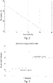
- Fig.2 shows an example of a temperature calibration obtained on a group of ten analyser instruments of the same apparatus type, ABL90 available from Radiometer Denmark.
- a schematic of the apparatus type is given in Fig.1 .
- the ten individual instruments were placed in a climate test room allowing to precisely controlling a room temperature in the range between 10°C and 32°C. At a given room temperature, the instruments were allowed to settle. With the instruments in thermal equilibrium at a given room temperature, a series of QC-measurements were performed, injecting a liquid sample of a QC-solution through the inlet into the measurement chamber by aspiration from the outlet by a pump, i.e. by applying suction from the downstream end of the measurement chamber.
- the injection was performed at a fixed flow rate of 65 ⁇ l/s (microliters per second) as controlled by the flow handling system.
- the liquid sample Prior to injection, the liquid sample has the same temperature as the room temperature.
- the liquid sample is then heated to a target temperature by the thermostatic sample heater device.
- the target temperature was set to 37°C for all experiments.
- the analyser assembly of the apparatus type used is encapsulated by a thermostatic encapsulation, which for all experiments also was set to the same temperature as the target temperature of the measurement chamber, i.e. to 37°C. Thereby a particularly well-controlled thermal behaviour is achieved for the measurement chamber as discussed above.
- a parameter representative of the heating power applied by the sample heater device is then retrieved from the sample heater device.
- the sample heater device of the above apparatus type is configured to control the heating power applied by varying a duty cycle of a heater current applied to an electric heater in respect of a difference between the target temperature and an actual sample temperature as measured by a temperature sensor arranged in the measurement chamber.
- the duty cycle data may thus be used as a parameter that is representative of the heating power applied by the thermostatic sample heater device in order to bring the liquid sample injected at room temperature with the given flow rate of 65 ⁇ l/s to the target temperature.
- the same experiment was repeated for each instrument at a number of different room temperature settings. In the graph shown in Fig.2 , the room temperature, corresponding to the initial temperature of the liquid sample, is plotted against the corresponding duty cycle readings of the thermostatic heater device averaged over all ten instruments.
- the obtained relationship may be used as a calibration curve for determining the initial temperature of an injected sample.
- the temperature calibration curve of Fig.2 is valid for instruments of the same type and for a fixed flow rate setting of 65 ⁇ l/s chosen for the experiments.
- the flow data obtained from the fluid handling system is the flow rate setting.
- Potential instrument-specific variations in the temperature calibration may be determined and may be compensated accordingly by an instrument specific temperature calibration, if such variations are considered significant. For example, variations in the resistance of the electrical heater elements of different instruments may be compensated by applying a scaling factor to the duty cycle reading, which is proportional to the deviation of the instrument-specific heater element resistance from a nominal heater element resistance.
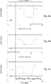
- Fig.3 shows from the same series of experiments as the data of Fig.2 a time series of duty cycle readings, wherein a first set of duty cycle readings was obtained for an injection flow rate setting of 35 ⁇ l/s and wherein, after a step change in flow rate setting, a second set of duty cycle readings was obtained for an injection flow rate setting of 65 ⁇ l/s. All duty cycle readings have been obtained for the same initial temperature as determined by the room temperature of 14°C, and on the same instrument.
- the graph of Fig.3 illustrates the injection flow rate dependency of the heating power applied by the thermostatic sample heater in order to bring the injected liquid sample from its initial temperature to the target temperature of 37°C.
- Fig .4a-c from the same series of experiments as the data of Figs.2 and 3 a composite plot with three series of p CO 2 measurements taken on three different QC-solutions of known composition: S9030 with a nominal value for p CO 2 of 30 mm Hg at 23°C ( Fig.4a ); S9040 with a nominal value for p CO 2 of 67 mm Hg at 23°C ( Fig.4b ); and S9050 with a nominal value for p CO 2 of 20 mm Hg at 23°C ( Fig.4c ).
- the p CO 2 measurements were taken at two different room temperatures over a span of several days, first maintaining a room temperature of 28°C, then reducing the room temperature to 13°C, and finally returning back to a room temperature of 28°C.
- the p CO 2 measurements were all performed using the same protocol, including timing, of filling the measurement chamber with a liquid sample, pre-heating the liquid sample during the filling procedure to the target temperature using the thermostatic sample heater device, and as soon as the target temperature was achieved, switching off the thermostatic sample heater device and obtain a p CO 2 sensor output reading.
- the obtained p CO 2 sensor output reading is plotted in the graphs together with respective upper limits, marked "HI”, and lower limits, marked "LOW", for each of the three QC-solutions.
- the upper and lower limits (HI, LOW) are determined with respect to the nominal value for the p CO 2 of the respective QC-solution, in agreement with the RiLi-B ⁇ K guidelines of 19 September 2014.
- Table 1 lists nominal compositions of the three QC-solutions. While the respective nominal values may be taken from such a table, the actual composition may slightly deviate from these tabulated values within production tolerances.
- the actual analyte composition for each solution in a solution pack lot is therefore typically included in a smart chip contained in each solution pack.
- the actual values for the nominal concentrations may thus be read into the processor unit when the solution pack is installed in an instrument. This allows for even better precision in the QC-procedure.
- the upper and lower limits (HI, LOW) shown in the Figs.4a-c have been determined using the above-mentioned Rili-B ⁇ K guidelines based on the actual values for the nominal p CO 2 of the respective QC-solutions (S9030, S9040, S9050).
- Table 1 Composition table with nominal p CO 2 values at 23°C for QC-solutions S9030, S9040, and S9050 Concentration Substance Unit S9030 (QC 1) S9040 (QC 2) S9050 (QC 3) Solution Solution Gas p O 2 (at 760 mmHg ) Solution pH 7.2 6.8 NA 7.5 p CO 2 mmHg 30 67 NA 20 p O 2 mmHg 180 300 (42.07 %) 20 c Na + mmol/L 140 118 NA 175 c K - mmol/L 4 7 NA 1.8 c Cl - mmol/L 105 95 NA 125 c Ca 2- mmol/L 0.8 1.65 NA 0.3 c Glu mmol/L 0 15 NA 7 c Lac mmol/L 0 8 NA 4 c tBil ⁇ ⁇ mol/L 0 300 NA 450 c tHb mmol/L 0 8 NA 12 s O 2 % 97 NA 70 FO 2 Hb %
Landscapes
- Health & Medical Sciences (AREA)
- Life Sciences & Earth Sciences (AREA)
- Engineering & Computer Science (AREA)
- Biomedical Technology (AREA)
- Hematology (AREA)
- Chemical & Material Sciences (AREA)
- Physics & Mathematics (AREA)
- Molecular Biology (AREA)
- Analytical Chemistry (AREA)
- Biochemistry (AREA)
- General Health & Medical Sciences (AREA)
- General Physics & Mathematics (AREA)
- Immunology (AREA)
- Pathology (AREA)
- Urology & Nephrology (AREA)
- Ecology (AREA)
- Biophysics (AREA)
- Food Science & Technology (AREA)
- Medicinal Chemistry (AREA)
- Electrochemistry (AREA)
- Chemical Kinetics & Catalysis (AREA)
- Investigating Or Analyzing Materials Using Thermal Means (AREA)
- Automatic Analysis And Handling Materials Therefor (AREA)
- Apparatus Associated With Microorganisms And Enzymes (AREA)
Claims (17)
- Appareil (1)pour l'analyse d'échantillons de liquide biologique, l'appareil comprenant :- une chambre de mesure (2) définissant un volume d'échantillon avec une entrée (6) et une sortie (7),- un système de manipulation de fluide (20)adapté pour alimenter un échantillon de liquide au volume d'échantillon par l'entrée et pour enlever l'échantillon de liquide par la sortie ;- au moins un capteur d'analyte (3a-i, 4) en contact avec le volume d'échantillon,le capteur d'analyte étant adapté pour produire une sortie de capteur d'analyte représentant une mesure quantitative d'un analyte dans l'échantillon de liquide ;- un dispositif d'appareil de chauffage d'échantillon thermostatique (30)adapté pour commander une température 'échantillon du liquide d'échantillon dans la chambre de mesure ; et- une unité de processeur (8) ;l'unité de processeur étant configurée pour déterminer une température initiale de l'échantillon de liquide injecté dans la chambre de mesure sur les données d'écoulement du système de manipulation de fluide et des données de chauffage d'échantillon du dispositif d'appareil de chauffage d'échantillon.
- Appareil selon la revendication 1, dans lequel les données d'écoulement de fluide comprennent un paramètre représentatif du débit du liquide injecté au volume d'échantillon et les données de chauffage d'échantillon comprennent un paramètre représentatif de la puissance de chauffage appliquée par le dispositif d'appareil de chauffage d'échantillon thermostatique pour établir une température cible dans le volume d'échantillon dans des conditions d'écoulement stationnaire.
- Appareil selon l'une quelconque des revendications précédentes, dans lequel le dispositif d'appareil de chauffage d'échantillon thermostatique a pour but de réguler une température d'échantillon d'un échantillon de liquide dans la chambre de mesure selon un réglage de température cible.
- Appareil selon l'une quelconque des revendications précédentes, dans lequel le dispositif d'appareil de chauffage d'échantillon thermostatique comprend un élément de chauffage électrique, tel qu'un élément de chauffage résistant, attaché physiquement à ou intégré avec les parois de la chambre de mesure.
- Appareil selon l'une quelconque des revendications précédentes, dans lequel une température cible dans le volume d'échantillon se situe dans la plage comprise entre 35 °C et 39 °C, ou entre 36 °C et 38 °C et de préférence à 37 °C.
- Appareil selon l'une quelconque des revendications précédentes, dans lequel l'appareil comprend une encapsulation isothermique de la chambre de mesure, l'encapsulation isothermique enfermant la chambre de mesure avec des surfaces internes thermiquement contrôlées et/ou thermiquement régulées.
- Appareil selon la revendication 6, dans lequel la température des surfaces internes de l'encapsulation isothermique est contrôlée et/ou régulée à une température fixe, qui de préférence entre toutes est égale à la température cible de la chambre de mesure.
- Appareil selon la revendication 1,
dans lequel l'unité de processeur est en outre configurée pour corriger la sortie du capteur d'analyte sur la base de la température initiale déterminée. - Appareil selon la revendication 1 ou la revendication 8, dans lequel l'analyte est le CO2.
- Appareil selon l'une quelconque des revendications 1, 8, 9, dans lequel la sortie de capteur d'analyte représente une mesure quantitative de la pression partielle de CO2, pCO2, dans l'échantillon de liquide.
- Appareil selon l'une quelconque des revendications 1, 8 à 10,
dans lequel l'unité de processeur est en outre configurée pour comparer la sortie du capteur d'analyte à une valeur nominale et/ou l'unité de processeur étant configurée pour comparer la sortie du capteur d'analyte à une plage de validité avec une valeur de limite supérieure et une valeur de limite inférieure. - Appareil selon la revendication 11,
dans lequel le dispositif de processeur fournit en outre une sortie de validation en relation au capteur d'analyte sur la base de la comparaison. - Procédé pour l'analyse d'échantillons de liquide biologique, le procédé comprenant :- l'injection d'un échantillon de liquide dans un volume d'échantillon défini à l'intérieur d'une chambre de mesure (2), l'échantillon de liquide ayant une température initiale, l'écoulement d'injection étant commandé au moyen d'un système de manipulation de fluide (20) ;- après l'injection, le chauffage de l'échantillon de liquide injecté à une température cible au moyen d'un dispositif d'appareil de chauffage d'échantillon thermostatique (30) ;- la détermination de la température initiale de l'échantillon de liquide injecté dans la chambre de mesure sur la base des données d'écoulement de fluide du système de manipulation de fluide et des données de chauffage d'échantillon du dispositif d'appareil de chauffage d'échantillon ; et- la mise de l'échantillon de liquide à l'intérieur du volume d'échantillon en contact avec au moins un capteur d'analyte (3a-i, 4) et la production d'une sortie de capteur d'analyte, la sortie de capteur d'analyte étant représentative d'une mesure quantitative en regard d'une quantité d'un analyte correspondant dans l'échantillon de liquide.
- Procédé selon la revendication 13,
dans lequel les données d'écoulement de fluide comprennent un paramètre représentatif du débit de l'échantillon de liquide injecté dans le volume d'échantillon et les données de chauffage d'échantillon comprennent un paramètre représentatif de la puissance de chauffage appliquée par le dispositif d'appareil de chauffage d'échantillon thermostatique pour établir une température cible dans le volume d'échantillon dans des conditions d'écoulement stationnaire. - Procédé selon la revendication 13, le procédé comprenant en outre :- la correction de la sortie du capteur d'analyte sur la base de la température initiale déterminée.
- Procédé selon la revendication 13 ou 15,
dans lequel la sortie de capteur d'analyte est corrigée en utilisant une formule de correction, la formule de correction étant déterminée avant d'utiliser des solutions de teneur d'analyte connue/calibrée et la mesure sur les solutions connues à des températures différentes. - Procédé selon l'une quelconque des revendications 15 ou 16,
dans lequel la sortie de capteur d'analyte est corrigée en utilisant une formule de correction, la formule de correction étant polynomiale, de préférence une fonction linéaire.
Applications Claiming Priority (2)
| Application Number | Priority Date | Filing Date | Title |
|---|---|---|---|
| DKPA201600746 | 2016-12-07 | ||
| PCT/EP2017/080906 WO2018104134A1 (fr) | 2016-12-07 | 2017-11-30 | Système et procédé d'estimation de la température d'un échantillon liquide |
Publications (2)
| Publication Number | Publication Date |
|---|---|
| EP3552015A1 EP3552015A1 (fr) | 2019-10-16 |
| EP3552015B1 true EP3552015B1 (fr) | 2023-01-18 |
Family
ID=60515395
Family Applications (1)
| Application Number | Title | Priority Date | Filing Date |
|---|---|---|---|
| EP17807848.1A Active EP3552015B1 (fr) | 2016-12-07 | 2017-11-30 | Système et procédé d'estimation de la température d'un échantillon liquide |
Country Status (6)
| Country | Link |
|---|---|
| US (1) | US11422107B2 (fr) |
| EP (1) | EP3552015B1 (fr) |
| JP (1) | JP6748781B2 (fr) |
| CN (1) | CN109983341B (fr) |
| DK (1) | DK3552015T3 (fr) |
| WO (1) | WO2018104134A1 (fr) |
Families Citing this family (6)
| Publication number | Priority date | Publication date | Assignee | Title |
|---|---|---|---|---|
| EP3994462A1 (fr) * | 2019-07-05 | 2022-05-11 | Radiometer Medical ApS | Dispositif capteur |
| WO2022008714A1 (fr) * | 2020-07-10 | 2022-01-13 | Radiometer Medical Aps | Analyseur des gaz de sang et système comprenant un analyseur des gaz du sang et son utilisation |
| CN115776867A (zh) * | 2020-07-10 | 2023-03-10 | 雷迪奥米特医学公司 | 血气分析仪和包括血气分析仪的系统及其用途 |
| GB2600398B (en) * | 2020-10-21 | 2023-04-05 | Otter Controls Ltd | Liquid heating and dispensing apparatus and method |
| EP4113531A1 (fr) | 2021-06-29 | 2023-01-04 | Radiometer Medical ApS | Système et procédé de maintenance prédictive |
| WO2025128481A1 (fr) * | 2023-12-14 | 2025-06-19 | Siemens Healthcare Diagnostics Inc. | Correction de données d'étalonnage utilisées par des analyseurs de diagnostic sur la base de conditions de stockage de réactifs |
Citations (1)
| Publication number | Priority date | Publication date | Assignee | Title |
|---|---|---|---|---|
| US6114176A (en) * | 1994-07-29 | 2000-09-05 | Gambro Ab | Method for measuring the concentration of a substance in a solution |
Family Cites Families (24)
| Publication number | Priority date | Publication date | Assignee | Title |
|---|---|---|---|---|
| US4115230A (en) | 1977-01-06 | 1978-09-19 | Paul Beckman | Partial oxygen measurement system |
| DK421880A (da) * | 1980-10-06 | 1982-04-07 | Radiometer As | Apparat til analyse af biologiske vaesker |
| EP0616210A1 (fr) * | 1993-03-17 | 1994-09-21 | Ciba-Geigy Ag | Cellule à circulation de fluide pour des mesures calorimétriques |
| WO1998032013A1 (fr) * | 1997-01-17 | 1998-07-23 | Via Medical Corporation | Procede pour etalonner des capteurs utilises dans les tests de diagnostic |
| CA2408574A1 (fr) | 2000-05-24 | 2001-11-29 | Micronics, Inc. | Boucle microfluidique servant a produire un gradient de concentration |
| DE10143137C1 (de) | 2001-09-03 | 2003-04-17 | Fresenius Medical Care De Gmbh | Meßvorrichtung und -verfahren zur Bestimmung von Parametern medizinischer Flüssigkeiten sowie Verfahren zur Kalibrierung einer derartigen Vorrichtung |
| US6908224B2 (en) * | 2002-05-21 | 2005-06-21 | Kendro Laboratory Products, Lp | Temperature sensor pre-calibration method and apparatus |
| AT411400B (de) * | 2002-05-31 | 2003-12-29 | Hoffmann La Roche | Verfahren und vorrichtung zur messung von blutgasparametern |
| ATE485507T1 (de) | 2002-10-30 | 2010-11-15 | Radiometer Medical Aps | Verfahren zur durchführung der kalibration und qualitätskontrolle eines sensors und vorrichtung zur durchführung des verfahrens |
| US7043374B2 (en) | 2003-03-26 | 2006-05-09 | Celerity, Inc. | Flow sensor signal conversion |
| US20050255483A1 (en) | 2004-05-14 | 2005-11-17 | Stratagene California | System and method for smoothing melting curve data |
| US7127366B2 (en) | 2005-01-12 | 2006-10-24 | Honeywell International Inc. | Automatic thermal conductivity compensation for fluid flow sensing using chemometrics |
| US7467027B2 (en) | 2006-01-26 | 2008-12-16 | Mks Instruments, Inc. | Compensation for thermal siphoning in mass flow controllers |
| CN100435729C (zh) | 2007-01-08 | 2008-11-26 | 何宗彦 | 无创快速血糖检测仪及其血糖检测方法 |
| EP1986007A1 (fr) * | 2007-04-27 | 2008-10-29 | Radiometer Medical ApS | Ensemble de capteurs pour des fluides de corps |
| DE102007023823B4 (de) | 2007-05-21 | 2014-12-18 | Abb Ag | Thermischer Massendurchflussmesser und Verfahren zu seinem Betrieb |
| JP2009074872A (ja) | 2007-09-19 | 2009-04-09 | Olympus Corp | 洗浄機構、自動分析装置および洗浄方法 |
| AT506798B1 (de) | 2009-01-13 | 2009-12-15 | Smart Medical Solutions Gmbh | Vorrichtung zur messung zumindest eines parameters einer arteriellen blutprobe |
| CN102917796B (zh) * | 2010-04-20 | 2015-04-01 | 科贝特研究私人有限公司 | 温度控制方法和设备 |
| BR112013020675B1 (pt) | 2011-02-15 | 2022-01-25 | Hemosonics, Llc | Dispositivos e método para avaliação de hemostasia |
| IL213767A (en) * | 2011-06-23 | 2017-05-29 | Adler Michael | A method and device for measuring fluid flow rate |
| GB2508358B (en) | 2012-11-28 | 2014-10-29 | Microvisk Ltd | Apparatus and method for monitoring a sedimentation parameter in a fluid medium sample |
| US9458488B2 (en) | 2013-03-15 | 2016-10-04 | Nanomix, Inc. | Point of care sensor systems |
| GB2512842A (en) * | 2013-04-08 | 2014-10-15 | Sphere Medical Ltd | Sensor calibration method and apparatus |
-
2017
- 2017-11-30 EP EP17807848.1A patent/EP3552015B1/fr active Active
- 2017-11-30 CN CN201780070650.5A patent/CN109983341B/zh active Active
- 2017-11-30 WO PCT/EP2017/080906 patent/WO2018104134A1/fr not_active Ceased
- 2017-11-30 DK DK17807848.1T patent/DK3552015T3/da active
- 2017-11-30 JP JP2019524183A patent/JP6748781B2/ja active Active
- 2017-11-30 US US16/466,419 patent/US11422107B2/en active Active
Patent Citations (1)
| Publication number | Priority date | Publication date | Assignee | Title |
|---|---|---|---|---|
| US6114176A (en) * | 1994-07-29 | 2000-09-05 | Gambro Ab | Method for measuring the concentration of a substance in a solution |
Also Published As
| Publication number | Publication date |
|---|---|
| CN109983341A (zh) | 2019-07-05 |
| US11422107B2 (en) | 2022-08-23 |
| US20190346398A1 (en) | 2019-11-14 |
| CN109983341B (zh) | 2020-09-08 |
| JP2019536022A (ja) | 2019-12-12 |
| JP6748781B2 (ja) | 2020-09-02 |
| WO2018104134A1 (fr) | 2018-06-14 |
| EP3552015A1 (fr) | 2019-10-16 |
| DK3552015T3 (da) | 2023-04-03 |
Similar Documents
| Publication | Publication Date | Title |
|---|---|---|
| EP3552015B1 (fr) | Système et procédé d'estimation de la température d'un échantillon liquide | |
| US11015984B2 (en) | System and apparatus for determining ambient temperatures for a fluid analyte system | |
| CA2699386C (fr) | Systeme d'assurance qualite ameliore et procede de test au point d'intervention | |
| EP1467201B1 (fr) | Analyseur comportant une thermosonde | |
| US20040132193A1 (en) | Method of performing calibration and quality control of a sensor and apparatus for performing the method | |
| US20180128688A1 (en) | Fluid Property Measurement Devices, Methods, and Systems | |
| US20100158070A1 (en) | Method for Monitoring the Thermal Coupling of a Measuring Cell | |
| WO2020234728A1 (fr) | Système de compensation et procédé de détection de thermistance dans un biocapteur d'analyte | |
| EP1558921B1 (fr) | Procede destine a l'etalonnage et au controle de la qualite d'un capteur et dispositif destine a la mise en oeuvre de ce procede | |
| CN117043605A (zh) | 自动分析装置的温度调节系统 | |
| CN116859034A (zh) | 血气生化分析仪的温度异常判断方法和数据校正方法 | |
| US20220357355A1 (en) | Sensor device | |
| US20200300809A1 (en) | Ion Concentration Measurement Device | |
| JPH04191650A (ja) | イオン測定装置 | |
| US11041846B2 (en) | Test element analysis system for the analytical examination of a sample | |
| Armitage et al. | Optical kinetic method for calibration of spectrophotometer temperature: demonstration with the Cobas-Bio analyzer. |
Legal Events
| Date | Code | Title | Description |
|---|---|---|---|
| STAA | Information on the status of an ep patent application or granted ep patent |
Free format text: STATUS: UNKNOWN |
|
| STAA | Information on the status of an ep patent application or granted ep patent |
Free format text: STATUS: THE INTERNATIONAL PUBLICATION HAS BEEN MADE |
|
| PUAI | Public reference made under article 153(3) epc to a published international application that has entered the european phase |
Free format text: ORIGINAL CODE: 0009012 |
|
| STAA | Information on the status of an ep patent application or granted ep patent |
Free format text: STATUS: REQUEST FOR EXAMINATION WAS MADE |
|
| 17P | Request for examination filed |
Effective date: 20190625 |
|
| AK | Designated contracting states |
Kind code of ref document: A1 Designated state(s): AL AT BE BG CH CY CZ DE DK EE ES FI FR GB GR HR HU IE IS IT LI LT LU LV MC MK MT NL NO PL PT RO RS SE SI SK SM TR |
|
| AX | Request for extension of the european patent |
Extension state: BA ME |
|
| STAA | Information on the status of an ep patent application or granted ep patent |
Free format text: STATUS: EXAMINATION IS IN PROGRESS |
|
| DAV | Request for validation of the european patent (deleted) | ||
| DAX | Request for extension of the european patent (deleted) | ||
| 17Q | First examination report despatched |
Effective date: 20200319 |
|
| GRAP | Despatch of communication of intention to grant a patent |
Free format text: ORIGINAL CODE: EPIDOSNIGR1 |
|
| STAA | Information on the status of an ep patent application or granted ep patent |
Free format text: STATUS: GRANT OF PATENT IS INTENDED |
|
| GRAJ | Information related to disapproval of communication of intention to grant by the applicant or resumption of examination proceedings by the epo deleted |
Free format text: ORIGINAL CODE: EPIDOSDIGR1 |
|
| GRAP | Despatch of communication of intention to grant a patent |
Free format text: ORIGINAL CODE: EPIDOSNIGR1 |
|
| STAA | Information on the status of an ep patent application or granted ep patent |
Free format text: STATUS: EXAMINATION IS IN PROGRESS |
|
| GRAP | Despatch of communication of intention to grant a patent |
Free format text: ORIGINAL CODE: EPIDOSNIGR1 |
|
| STAA | Information on the status of an ep patent application or granted ep patent |
Free format text: STATUS: GRANT OF PATENT IS INTENDED |
|
| INTG | Intention to grant announced |
Effective date: 20210303 |
|
| INTG | Intention to grant announced |
Effective date: 20210319 |
|
| INTG | Intention to grant announced |
Effective date: 20210325 |
|
| GRAJ | Information related to disapproval of communication of intention to grant by the applicant or resumption of examination proceedings by the epo deleted |
Free format text: ORIGINAL CODE: EPIDOSDIGR1 |
|
| STAA | Information on the status of an ep patent application or granted ep patent |
Free format text: STATUS: EXAMINATION IS IN PROGRESS |
|
| INTC | Intention to grant announced (deleted) | ||
| GRAP | Despatch of communication of intention to grant a patent |
Free format text: ORIGINAL CODE: EPIDOSNIGR1 |
|
| STAA | Information on the status of an ep patent application or granted ep patent |
Free format text: STATUS: GRANT OF PATENT IS INTENDED |
|
| GRAJ | Information related to disapproval of communication of intention to grant by the applicant or resumption of examination proceedings by the epo deleted |
Free format text: ORIGINAL CODE: EPIDOSDIGR1 |
|
| GRAP | Despatch of communication of intention to grant a patent |
Free format text: ORIGINAL CODE: EPIDOSNIGR1 |
|
| INTG | Intention to grant announced |
Effective date: 20211014 |
|
| INTG | Intention to grant announced |
Effective date: 20211027 |
|
| GRAJ | Information related to disapproval of communication of intention to grant by the applicant or resumption of examination proceedings by the epo deleted |
Free format text: ORIGINAL CODE: EPIDOSDIGR1 |
|
| STAA | Information on the status of an ep patent application or granted ep patent |
Free format text: STATUS: EXAMINATION IS IN PROGRESS |
|
| GRAP | Despatch of communication of intention to grant a patent |
Free format text: ORIGINAL CODE: EPIDOSNIGR1 |
|
| STAA | Information on the status of an ep patent application or granted ep patent |
Free format text: STATUS: GRANT OF PATENT IS INTENDED |
|
| INTC | Intention to grant announced (deleted) | ||
| INTG | Intention to grant announced |
Effective date: 20220325 |
|
| GRAJ | Information related to disapproval of communication of intention to grant by the applicant or resumption of examination proceedings by the epo deleted |
Free format text: ORIGINAL CODE: EPIDOSDIGR1 |
|
| STAA | Information on the status of an ep patent application or granted ep patent |
Free format text: STATUS: EXAMINATION IS IN PROGRESS |
|
| GRAP | Despatch of communication of intention to grant a patent |
Free format text: ORIGINAL CODE: EPIDOSNIGR1 |
|
| STAA | Information on the status of an ep patent application or granted ep patent |
Free format text: STATUS: GRANT OF PATENT IS INTENDED |
|
| INTC | Intention to grant announced (deleted) | ||
| INTG | Intention to grant announced |
Effective date: 20220803 |
|
| GRAS | Grant fee paid |
Free format text: ORIGINAL CODE: EPIDOSNIGR3 |
|
| GRAA | (expected) grant |
Free format text: ORIGINAL CODE: 0009210 |
|
| STAA | Information on the status of an ep patent application or granted ep patent |
Free format text: STATUS: THE PATENT HAS BEEN GRANTED |
|
| AK | Designated contracting states |
Kind code of ref document: B1 Designated state(s): AL AT BE BG CH CY CZ DE DK EE ES FI FR GB GR HR HU IE IS IT LI LT LU LV MC MK MT NL NO PL PT RO RS SE SI SK SM TR |
|
| REG | Reference to a national code |
Ref country code: GB Ref legal event code: FG4D |
|
| REG | Reference to a national code |
Ref country code: DE Ref legal event code: R096 Ref document number: 602017065613 Country of ref document: DE |
|
| REG | Reference to a national code |
Ref country code: CH Ref legal event code: EP |
|
| REG | Reference to a national code |
Ref country code: AT Ref legal event code: REF Ref document number: 1544978 Country of ref document: AT Kind code of ref document: T Effective date: 20230215 Ref country code: IE Ref legal event code: FG4D |
|
| REG | Reference to a national code |
Ref country code: DK Ref legal event code: T3 Effective date: 20230329 |
|
| REG | Reference to a national code |
Ref country code: LT Ref legal event code: MG9D |
|
| REG | Reference to a national code |
Ref country code: NL Ref legal event code: MP Effective date: 20230118 |
|
| REG | Reference to a national code |
Ref country code: AT Ref legal event code: MK05 Ref document number: 1544978 Country of ref document: AT Kind code of ref document: T Effective date: 20230118 |
|
| PG25 | Lapsed in a contracting state [announced via postgrant information from national office to epo] |
Ref country code: NL Free format text: LAPSE BECAUSE OF FAILURE TO SUBMIT A TRANSLATION OF THE DESCRIPTION OR TO PAY THE FEE WITHIN THE PRESCRIBED TIME-LIMIT Effective date: 20230118 |
|
| P01 | Opt-out of the competence of the unified patent court (upc) registered |
Effective date: 20230530 |
|
| PG25 | Lapsed in a contracting state [announced via postgrant information from national office to epo] |
Ref country code: RS Free format text: LAPSE BECAUSE OF FAILURE TO SUBMIT A TRANSLATION OF THE DESCRIPTION OR TO PAY THE FEE WITHIN THE PRESCRIBED TIME-LIMIT Effective date: 20230118 Ref country code: PT Free format text: LAPSE BECAUSE OF FAILURE TO SUBMIT A TRANSLATION OF THE DESCRIPTION OR TO PAY THE FEE WITHIN THE PRESCRIBED TIME-LIMIT Effective date: 20230518 Ref country code: NO Free format text: LAPSE BECAUSE OF FAILURE TO SUBMIT A TRANSLATION OF THE DESCRIPTION OR TO PAY THE FEE WITHIN THE PRESCRIBED TIME-LIMIT Effective date: 20230418 Ref country code: LV Free format text: LAPSE BECAUSE OF FAILURE TO SUBMIT A TRANSLATION OF THE DESCRIPTION OR TO PAY THE FEE WITHIN THE PRESCRIBED TIME-LIMIT Effective date: 20230118 Ref country code: LT Free format text: LAPSE BECAUSE OF FAILURE TO SUBMIT A TRANSLATION OF THE DESCRIPTION OR TO PAY THE FEE WITHIN THE PRESCRIBED TIME-LIMIT Effective date: 20230118 Ref country code: HR Free format text: LAPSE BECAUSE OF FAILURE TO SUBMIT A TRANSLATION OF THE DESCRIPTION OR TO PAY THE FEE WITHIN THE PRESCRIBED TIME-LIMIT Effective date: 20230118 Ref country code: ES Free format text: LAPSE BECAUSE OF FAILURE TO SUBMIT A TRANSLATION OF THE DESCRIPTION OR TO PAY THE FEE WITHIN THE PRESCRIBED TIME-LIMIT Effective date: 20230118 Ref country code: AT Free format text: LAPSE BECAUSE OF FAILURE TO SUBMIT A TRANSLATION OF THE DESCRIPTION OR TO PAY THE FEE WITHIN THE PRESCRIBED TIME-LIMIT Effective date: 20230118 |
|
| PG25 | Lapsed in a contracting state [announced via postgrant information from national office to epo] |
Ref country code: SE Free format text: LAPSE BECAUSE OF FAILURE TO SUBMIT A TRANSLATION OF THE DESCRIPTION OR TO PAY THE FEE WITHIN THE PRESCRIBED TIME-LIMIT Effective date: 20230118 Ref country code: PL Free format text: LAPSE BECAUSE OF FAILURE TO SUBMIT A TRANSLATION OF THE DESCRIPTION OR TO PAY THE FEE WITHIN THE PRESCRIBED TIME-LIMIT Effective date: 20230118 Ref country code: IS Free format text: LAPSE BECAUSE OF FAILURE TO SUBMIT A TRANSLATION OF THE DESCRIPTION OR TO PAY THE FEE WITHIN THE PRESCRIBED TIME-LIMIT Effective date: 20230518 Ref country code: GR Free format text: LAPSE BECAUSE OF FAILURE TO SUBMIT A TRANSLATION OF THE DESCRIPTION OR TO PAY THE FEE WITHIN THE PRESCRIBED TIME-LIMIT Effective date: 20230419 Ref country code: FI Free format text: LAPSE BECAUSE OF FAILURE TO SUBMIT A TRANSLATION OF THE DESCRIPTION OR TO PAY THE FEE WITHIN THE PRESCRIBED TIME-LIMIT Effective date: 20230118 |
|
| REG | Reference to a national code |
Ref country code: DE Ref legal event code: R097 Ref document number: 602017065613 Country of ref document: DE |
|
| PG25 | Lapsed in a contracting state [announced via postgrant information from national office to epo] |
Ref country code: SM Free format text: LAPSE BECAUSE OF FAILURE TO SUBMIT A TRANSLATION OF THE DESCRIPTION OR TO PAY THE FEE WITHIN THE PRESCRIBED TIME-LIMIT Effective date: 20230118 Ref country code: RO Free format text: LAPSE BECAUSE OF FAILURE TO SUBMIT A TRANSLATION OF THE DESCRIPTION OR TO PAY THE FEE WITHIN THE PRESCRIBED TIME-LIMIT Effective date: 20230118 Ref country code: EE Free format text: LAPSE BECAUSE OF FAILURE TO SUBMIT A TRANSLATION OF THE DESCRIPTION OR TO PAY THE FEE WITHIN THE PRESCRIBED TIME-LIMIT Effective date: 20230118 Ref country code: CZ Free format text: LAPSE BECAUSE OF FAILURE TO SUBMIT A TRANSLATION OF THE DESCRIPTION OR TO PAY THE FEE WITHIN THE PRESCRIBED TIME-LIMIT Effective date: 20230118 |
|
| PLBE | No opposition filed within time limit |
Free format text: ORIGINAL CODE: 0009261 |
|
| STAA | Information on the status of an ep patent application or granted ep patent |
Free format text: STATUS: NO OPPOSITION FILED WITHIN TIME LIMIT |
|
| PG25 | Lapsed in a contracting state [announced via postgrant information from national office to epo] |
Ref country code: SK Free format text: LAPSE BECAUSE OF FAILURE TO SUBMIT A TRANSLATION OF THE DESCRIPTION OR TO PAY THE FEE WITHIN THE PRESCRIBED TIME-LIMIT Effective date: 20230118 |
|
| 26N | No opposition filed |
Effective date: 20231019 |
|
| PG25 | Lapsed in a contracting state [announced via postgrant information from national office to epo] |
Ref country code: SI Free format text: LAPSE BECAUSE OF FAILURE TO SUBMIT A TRANSLATION OF THE DESCRIPTION OR TO PAY THE FEE WITHIN THE PRESCRIBED TIME-LIMIT Effective date: 20230118 |
|
| PG25 | Lapsed in a contracting state [announced via postgrant information from national office to epo] |
Ref country code: IT Free format text: LAPSE BECAUSE OF FAILURE TO SUBMIT A TRANSLATION OF THE DESCRIPTION OR TO PAY THE FEE WITHIN THE PRESCRIBED TIME-LIMIT Effective date: 20230118 |
|
| PG25 | Lapsed in a contracting state [announced via postgrant information from national office to epo] |
Ref country code: MC Free format text: LAPSE BECAUSE OF FAILURE TO SUBMIT A TRANSLATION OF THE DESCRIPTION OR TO PAY THE FEE WITHIN THE PRESCRIBED TIME-LIMIT Effective date: 20230118 |
|
| PG25 | Lapsed in a contracting state [announced via postgrant information from national office to epo] |
Ref country code: LU Free format text: LAPSE BECAUSE OF NON-PAYMENT OF DUE FEES Effective date: 20231130 |
|
| PG25 | Lapsed in a contracting state [announced via postgrant information from national office to epo] |
Ref country code: MC Free format text: LAPSE BECAUSE OF FAILURE TO SUBMIT A TRANSLATION OF THE DESCRIPTION OR TO PAY THE FEE WITHIN THE PRESCRIBED TIME-LIMIT Effective date: 20230118 Ref country code: LU Free format text: LAPSE BECAUSE OF NON-PAYMENT OF DUE FEES Effective date: 20231130 |
|
| REG | Reference to a national code |
Ref country code: BE Ref legal event code: MM Effective date: 20231130 |
|
| REG | Reference to a national code |
Ref country code: IE Ref legal event code: MM4A |
|
| PG25 | Lapsed in a contracting state [announced via postgrant information from national office to epo] |
Ref country code: IE Free format text: LAPSE BECAUSE OF NON-PAYMENT OF DUE FEES Effective date: 20231130 |
|
| PG25 | Lapsed in a contracting state [announced via postgrant information from national office to epo] |
Ref country code: BE Free format text: LAPSE BECAUSE OF NON-PAYMENT OF DUE FEES Effective date: 20231130 |
|
| PG25 | Lapsed in a contracting state [announced via postgrant information from national office to epo] |
Ref country code: IE Free format text: LAPSE BECAUSE OF NON-PAYMENT OF DUE FEES Effective date: 20231130 Ref country code: BE Free format text: LAPSE BECAUSE OF NON-PAYMENT OF DUE FEES Effective date: 20231130 |
|
| PG25 | Lapsed in a contracting state [announced via postgrant information from national office to epo] |
Ref country code: BG Free format text: LAPSE BECAUSE OF FAILURE TO SUBMIT A TRANSLATION OF THE DESCRIPTION OR TO PAY THE FEE WITHIN THE PRESCRIBED TIME-LIMIT Effective date: 20230118 |
|
| PG25 | Lapsed in a contracting state [announced via postgrant information from national office to epo] |
Ref country code: BG Free format text: LAPSE BECAUSE OF FAILURE TO SUBMIT A TRANSLATION OF THE DESCRIPTION OR TO PAY THE FEE WITHIN THE PRESCRIBED TIME-LIMIT Effective date: 20230118 |
|
| PG25 | Lapsed in a contracting state [announced via postgrant information from national office to epo] |
Ref country code: CY Free format text: LAPSE BECAUSE OF FAILURE TO SUBMIT A TRANSLATION OF THE DESCRIPTION OR TO PAY THE FEE WITHIN THE PRESCRIBED TIME-LIMIT; INVALID AB INITIO Effective date: 20171130 |
|
| PG25 | Lapsed in a contracting state [announced via postgrant information from national office to epo] |
Ref country code: HU Free format text: LAPSE BECAUSE OF FAILURE TO SUBMIT A TRANSLATION OF THE DESCRIPTION OR TO PAY THE FEE WITHIN THE PRESCRIBED TIME-LIMIT; INVALID AB INITIO Effective date: 20171130 |
|
| REG | Reference to a national code |
Ref country code: CH Ref legal event code: U11 Free format text: ST27 STATUS EVENT CODE: U-0-0-U10-U11 (AS PROVIDED BY THE NATIONAL OFFICE) Effective date: 20251201 |
|
| PG25 | Lapsed in a contracting state [announced via postgrant information from national office to epo] |
Ref country code: TR Free format text: LAPSE BECAUSE OF FAILURE TO SUBMIT A TRANSLATION OF THE DESCRIPTION OR TO PAY THE FEE WITHIN THE PRESCRIBED TIME-LIMIT Effective date: 20230118 |
|
| PGFP | Annual fee paid to national office [announced via postgrant information from national office to epo] |
Ref country code: DE Payment date: 20251126 Year of fee payment: 9 |
|
| PGFP | Annual fee paid to national office [announced via postgrant information from national office to epo] |
Ref country code: GB Payment date: 20251125 Year of fee payment: 9 |
|
| PGFP | Annual fee paid to national office [announced via postgrant information from national office to epo] |
Ref country code: DK Payment date: 20251124 Year of fee payment: 9 |
|
| PGFP | Annual fee paid to national office [announced via postgrant information from national office to epo] |
Ref country code: FR Payment date: 20251125 Year of fee payment: 9 |
|
| PGFP | Annual fee paid to national office [announced via postgrant information from national office to epo] |
Ref country code: CH Payment date: 20251201 Year of fee payment: 9 |