EP3551947B1 - Regenerator for a cryo-cooler with helium as a working gas, a method for producing such a regenerator, and a cryo-cooler comprising such a regenerator - Google Patents
Regenerator for a cryo-cooler with helium as a working gas, a method for producing such a regenerator, and a cryo-cooler comprising such a regenerator Download PDFInfo
- Publication number
- EP3551947B1 EP3551947B1 EP17832047.9A EP17832047A EP3551947B1 EP 3551947 B1 EP3551947 B1 EP 3551947B1 EP 17832047 A EP17832047 A EP 17832047A EP 3551947 B1 EP3551947 B1 EP 3551947B1
- Authority
- EP
- European Patent Office
- Prior art keywords
- regenerator
- cell
- cells
- working gas
- cavities
- Prior art date
- Legal status (The legal status is an assumption and is not a legal conclusion. Google has not performed a legal analysis and makes no representation as to the accuracy of the status listed.)
- Active
Links
- 239000007789 gas Substances 0.000 title claims description 52
- 239000001307 helium Substances 0.000 title claims description 50
- 229910052734 helium Inorganic materials 0.000 title claims description 50
- SWQJXJOGLNCZEY-UHFFFAOYSA-N helium atom Chemical compound [He] SWQJXJOGLNCZEY-UHFFFAOYSA-N 0.000 title claims description 50
- 238000004519 manufacturing process Methods 0.000 title claims description 10
- 210000004027 cell Anatomy 0.000 claims description 99
- 210000002421 cell wall Anatomy 0.000 claims description 31
- 238000010146 3D printing Methods 0.000 claims description 19
- 238000005338 heat storage Methods 0.000 claims description 5
- 230000000295 complement effect Effects 0.000 claims description 3
- 239000011232 storage material Substances 0.000 claims description 3
- 239000000463 material Substances 0.000 description 11
- 229910052761 rare earth metal Inorganic materials 0.000 description 6
- 239000011159 matrix material Substances 0.000 description 5
- -1 Rare earth compounds Chemical class 0.000 description 4
- 229910052751 metal Inorganic materials 0.000 description 4
- 239000002184 metal Substances 0.000 description 4
- 239000011324 bead Substances 0.000 description 3
- 238000001816 cooling Methods 0.000 description 3
- 238000007373 indentation Methods 0.000 description 3
- 230000002093 peripheral effect Effects 0.000 description 3
- 238000004026 adhesive bonding Methods 0.000 description 2
- 230000007423 decrease Effects 0.000 description 2
- 238000000034 method Methods 0.000 description 2
- 238000005192 partition Methods 0.000 description 2
- 238000003466 welding Methods 0.000 description 2
- 238000005299 abrasion Methods 0.000 description 1
- 239000003463 adsorbent Substances 0.000 description 1
- 239000003990 capacitor Substances 0.000 description 1
- 238000012512 characterization method Methods 0.000 description 1
- 230000006835 compression Effects 0.000 description 1
- 238000007906 compression Methods 0.000 description 1
- 238000010276 construction Methods 0.000 description 1
- 230000006866 deterioration Effects 0.000 description 1
- 239000000428 dust Substances 0.000 description 1
- 230000000694 effects Effects 0.000 description 1
- 239000011521 glass Substances 0.000 description 1
- 238000009413 insulation Methods 0.000 description 1
- 238000005457 optimization Methods 0.000 description 1
- 239000002245 particle Substances 0.000 description 1
- 230000035699 permeability Effects 0.000 description 1
- 150000002910 rare earth metals Chemical class 0.000 description 1
Images

Classifications
-
- F—MECHANICAL ENGINEERING; LIGHTING; HEATING; WEAPONS; BLASTING
- F25—REFRIGERATION OR COOLING; COMBINED HEATING AND REFRIGERATION SYSTEMS; HEAT PUMP SYSTEMS; MANUFACTURE OR STORAGE OF ICE; LIQUEFACTION SOLIDIFICATION OF GASES
- F25B—REFRIGERATION MACHINES, PLANTS OR SYSTEMS; COMBINED HEATING AND REFRIGERATION SYSTEMS; HEAT PUMP SYSTEMS
- F25B9/00—Compression machines, plants or systems, in which the refrigerant is air or other gas of low boiling point
- F25B9/14—Compression machines, plants or systems, in which the refrigerant is air or other gas of low boiling point characterised by the cycle used, e.g. Stirling cycle
- F25B9/145—Compression machines, plants or systems, in which the refrigerant is air or other gas of low boiling point characterised by the cycle used, e.g. Stirling cycle pulse-tube cycle
-
- F—MECHANICAL ENGINEERING; LIGHTING; HEATING; WEAPONS; BLASTING
- F25—REFRIGERATION OR COOLING; COMBINED HEATING AND REFRIGERATION SYSTEMS; HEAT PUMP SYSTEMS; MANUFACTURE OR STORAGE OF ICE; LIQUEFACTION SOLIDIFICATION OF GASES
- F25B—REFRIGERATION MACHINES, PLANTS OR SYSTEMS; COMBINED HEATING AND REFRIGERATION SYSTEMS; HEAT PUMP SYSTEMS
- F25B2309/00—Gas cycle refrigeration machines
- F25B2309/002—Gas cycle refrigeration machines with parallel working cold producing expansion devices in one circuit
-
- F—MECHANICAL ENGINEERING; LIGHTING; HEATING; WEAPONS; BLASTING
- F25—REFRIGERATION OR COOLING; COMBINED HEATING AND REFRIGERATION SYSTEMS; HEAT PUMP SYSTEMS; MANUFACTURE OR STORAGE OF ICE; LIQUEFACTION SOLIDIFICATION OF GASES
- F25B—REFRIGERATION MACHINES, PLANTS OR SYSTEMS; COMBINED HEATING AND REFRIGERATION SYSTEMS; HEAT PUMP SYSTEMS
- F25B2309/00—Gas cycle refrigeration machines
- F25B2309/003—Gas cycle refrigeration machines characterised by construction or composition of the regenerator
-
- F—MECHANICAL ENGINEERING; LIGHTING; HEATING; WEAPONS; BLASTING
- F25—REFRIGERATION OR COOLING; COMBINED HEATING AND REFRIGERATION SYSTEMS; HEAT PUMP SYSTEMS; MANUFACTURE OR STORAGE OF ICE; LIQUEFACTION SOLIDIFICATION OF GASES
- F25B—REFRIGERATION MACHINES, PLANTS OR SYSTEMS; COMBINED HEATING AND REFRIGERATION SYSTEMS; HEAT PUMP SYSTEMS
- F25B2309/00—Gas cycle refrigeration machines
- F25B2309/14—Compression machines, plants or systems characterised by the cycle used
- F25B2309/1408—Pulse-tube cycles with pulse tube having U-turn or L-turn type geometrical arrangements
-
- F—MECHANICAL ENGINEERING; LIGHTING; HEATING; WEAPONS; BLASTING
- F25—REFRIGERATION OR COOLING; COMBINED HEATING AND REFRIGERATION SYSTEMS; HEAT PUMP SYSTEMS; MANUFACTURE OR STORAGE OF ICE; LIQUEFACTION SOLIDIFICATION OF GASES
- F25B—REFRIGERATION MACHINES, PLANTS OR SYSTEMS; COMBINED HEATING AND REFRIGERATION SYSTEMS; HEAT PUMP SYSTEMS
- F25B2309/00—Gas cycle refrigeration machines
- F25B2309/14—Compression machines, plants or systems characterised by the cycle used
- F25B2309/1415—Pulse-tube cycles characterised by regenerator details
Definitions
- the invention relates to a regenerator for cryocoolers with helium as the working gas according to claim 1, a method for producing such a regenerator according to claims 13 and 14 and a cryocooler provided with such a regenerator according to claim 15.
- cryo-coolers e.g. B. Stirling, Gifford-McMahon and pulse tube coolers are operated regeneratively. i.e. the thermal capacity of a material is used to store the cold or to pre-cool warm gas as it enters the expansion chamber.
- a problem here is that at temperatures in the 2K to 20K range, the heat capacity of almost all materials decreases sharply. It is therefore very difficult to find materials that have a sufficiently high heat capacity in the range between 2K and 20K.
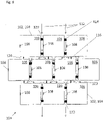
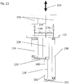
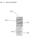
- 12 shows the typical structure of a two-stage pulse tube cooler with a first cold stage of 20 to approx. 30K and a second cold stage of 22 to approx. 2K.
- the first cold stage 220 includes a first pulse tube 224 and a first regenerator 226.
- the second cold stage 222 includes a second pulse tube 228 and a second regenerator 230 in accordance with the present invention. With the first cold stage 220 approx. 30K and with the second cold stage 222 approx. 4K are achieved.
- the first pulse tube 224, the first regenerator 226 and the second pulse tube 228 terminate in a connecting means 232 which separates the environment from the area to be cooled.
- Working gas is supplied and discharged in a pulsating manner by a pump (not shown) via working gas lines 234 .
- the working gas lines 234 open into the first regenerator 226 and via valves 236 there is a connection to the first pulse tube 224 and the second pulse tube 228 as well as to ballast volume 238.
- the second regenerator 230 in the second cold stage 222 consists of a first regenerator section 240 and a low-temperature - Regenerator section 242.
- the first regenerator section 240 consists of superimposed metal screens 244 - see figure 13 .
- the cryogenic regenerator section 242 contains rare earth connections, e.g. B. ErNi, HoCu 2 and the like.
- the structure of the second regenerator 230 is shown schematically in 11 shown. Rare earth compounds are relatively expensive. Furthermore, these materials are used in the form of beads 46 (100 to several 100 micrometers in diameter).
- a problem here is the fixation of the balls in the oscillating flow of the working gas, since any kind of movement leads to abrasion and thus dust, which drastically reduces the service life of the cryocooler.
- ball beds according to 13 a significant dead volume that does not contribute to heat exchange or cooling capacity.
- Helium is often used as a working gas in cryogenic coolers. In the temperature range from 2K to 20K, helium has a comparatively high heat capacity, which is equal to the heat capacity of rare earth compounds in this temperature range. It has therefore been proposed to use helium as the regenerator material. From the U.S. 2012/0304668 A1 , the, DE 10319510 A1 , the DE 102005007627 A1 , CN 104197591A , DE 19924184 A1 and the US4359872A closed hollow bodies made of glass or metal and filled with helium are known as regenerator structures. This basic idea has not yet resulted in a finished product.
- regenerator which is inexpensive in comparison to regenerators with rare earth compounds and which uses helium as the heat storage material and nevertheless has a simple structure.
- the regenerator consists of a hollow cell with heat-conducting cell walls.
- the outside of the cell walls at least partially delimits a flow channel for the working gas helium.
- the cavity is filled with helium as a heat storage material and is connected to the outside of the cell via a pressure equalization opening.
- the working gas, helium flows around the can-shaped cell, as a result of which heat transfer takes place via the cell walls between the working gas helium outside the cavity and the helium inside the cavity.
- the size of the cell(s) in relation to the size of the flow channel of the working gas is selected in such a way that the desired pressure differences are set between the high-pressure side and the low-pressure side of the regenerator with the smallest possible dead volume.
- the cell walls of the cell are very thin, so that the desired heat exchange can take place.
- the ratio of the volume of the cavity or cavities to the opening area or outflow resistance of the pressure equalization opening is chosen so that the pressure in the cavity or cavities in the working frequency range of cooler operation (approx. 1 to 60 Hz) hardly changes, or at least only slightly.
- This mode of operation can be compared to a capacitor at high frequencies - it is virtually unaware of the change in voltage if the capacity is high enough and the voltage change is small.
- the pressure in the cell would always fluctuate around the medium pressure of the cooling system, typically around 16 bar.
- the stable pressure is important because otherwise the volume of the cavity or cavities would be a large contributor to the "dead volume" if its pressure was between e.g.
- the opening area or the outflow resistance of the pressure compensation opening is selected in such a way that before the regenerator is put into operation and during the start-up phase, helium penetrates into the cavity or cavities due to the prevailing pressure conditions.
- the high outflow resistance of the pressure equalization opening results in the "condenser effect" explained above during the Pressure fluctuations in the area of the regenerator with the working frequency of a cooler.
- the temperature of the working gas helium and also of the helium in the regenerator cavities decreases. As a result, the volume of helium is reduced and helium continues to flow into the regenerator cavities via the pressure equalization opening. i.e.
- the pressure equalization opening has the form of a capillary.
- the cell is penetrated by flow channels that are delimited by cell walls. This results in an enlarged heat exchange surface and thus improved heat transfer between the helium in the cavities and the working gas outside.
- the flow channels are preferably designed as slots. The slits end short of the edge of the cell, preventing the cell from falling apart.
- the flow channels are formed as a plurality of slots that are straight and parallel to each other and terminate short of the edge of the cell so that the cell cannot fall apart.
- a circumferential channel is formed at the edge of the cell into which the multiple interconnected cavities open.
- the slit-shaped flow channels for working gas preferably run in a straight line and parallel to one another, on the one hand to minimize the flow resistance and on the other hand to uniformly close the tubular cavities between the shape. Due to the straightness and the parallelism, an equal distance is obtained in a simple manner between two flow channels.
- a single cell optionally with a plurality of tubular structures, can have the shape of a disc. Alternatively, multiple cells can be assembled into a disk shape. - Claim2.
- the arrangement in a row according to claim 3 increases the heat storage capacity of the regenerator.
- Thermal insulation between cells arranged one behind the other in the direction of flow of the working gas - claim 4 - prevents heat from being exchanged between the cavities in the direction of flow of the working gas.
- Such a heat exchange in the flow direction of the working gas would mean a short circuit of the regenerator; a heat exchange in the flow direction of the working gas does not contribute to the function of the regenerator.
- the thickness of the thermally insulating layer is preferably between 0.1 mm and 0.5 mm.
- the alignment elements according to claim 5 to 7 simplify the alignment of the flow channels of cells lying one on top of the other.
- the alignment elements are z.
- the shape of a capillary means that the cross-sectional area of the opening is very small compared to the surface area of the hollow body.
- the pressure equalization opening can also be provided by leaks that occur during the manufacture of the cells - claim 8.
- the size and thus the permeability of the pressure equalization opening are chosen so that during a working cycle of the regenerator, the pressure change in the cell is a maximum of 20% and preferably a maximum of 10%. This is an optimization process.
- the larger the capillary the greater the unwanted mass transfer, the greater the pressure fluctuations in the cell cavity and the faster the helium penetrates into the cavities when the regenerator is started up.
- the smaller the capillary the less compression work has to be done, but the longer it takes for the helium to penetrate the cavities when the regenerator is started up.
- the surfaces of the hollow bodies are provided with turbulence structures - claim 9
- the cross-sectional shapes of the tubular cavities according to claim 10 enable the manufacture of the regenerator by means of 3D printing (claim 14).
- the cuboid or rectangular shape of the cross sections of the cavities is optimal for heat exchange.
- Cells with tubular cavities with at least one sloping cell wall or with a triangular cross-section can be easily created using 3D printing.
- structures with vertical or sloping cell walls slopes of 45° or more
- a diamond-shaped cross-section, a pentagonal cross-section or a house-shaped cross-section is also suitable - claim 10.
- flow channels are arranged between the tubular cavities - claim 11.
- the disk-shaped regenerator in which the disk-shaped regenerator consists of one or more disk-shaped cells and each cell comprises two half-cells, means that both half-cells can be produced by means of 3D printing.
- the proportion of the volume of the cavities—and thus of the helium in the cavities—in the total volume of the regenerator increases compared to regenerators that only have one-piece cells. This increases the Heat storage capacity of the regenerator or the regenerator can be made more compact with the same heat capacity.
- cuboid cavities or elliptical cavities can be produced from two components as a whole or in two steps - claim 13 or 14.
- a first component with "open cavities” or with pot-shaped depressions is first produced.
- these depressions are then covered by second components.
- the first and second components are permanently joined together, e.g. B. by gluing or welding.
- regenerators according to the present invention are particularly suitable for Stirling, Gifford-McMahon or pulse tube coolers in particular - claim 15.
- the hollow bodies are made of metal and/or and can be made very thin compared to the prior art due to the pressure equalization opening, which reduces the heat transfer resistance between the helium inside the cavities and the helium working gas outside the cavities.
- the cell walls of the cavities preferably have a constant thickness, at least along the flow channels, and are in the range between 0.1 mm and 0.5 mm. Due to the constant wall thickness of the cell walls, a uniform heat transfer is achieved between the working gas helium in the flow channels and the helium in the cavities.
- the entire regenerator preferably has a thickness of 5 mm to 100 mm in the flow direction of the working gas.
- the Figures 1 and 2 show a first embodiment of the regenerator 1 according to the invention in its simplest form.
- the regenerator 1 consists of a cell 2 with cell walls 4 which enclose a cavity 6 .
- the cell walls 4 have an outside 4a and an inside 4i.
- a pressure equalization opening in the form of a capillary 8 passes through the cell walls 4 .
- the regenerator 1 has a circular cross-section and is arranged in a tubular flow channel 10 for the working gas helium.
- the interior of the cavity 6 is filled with helium as a regenerator medium or a heat-accumulating medium.
- the regenerator 1 or the cell 2 is dimensioned in such a way that an annular gap 12 remains between the tubular flow channel 10 for the working gas and the outside 4a of the cell wall 4 .
- the working gas helium can thus flow around the regenerator 1 and exchange heat with the helium in the cavity 6 via the heat-conducting cell walls 4 .
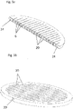
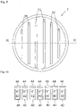
- Figures 3a and 3b show a second embodiment of the invention with a disc-shaped cell 2.
- the cell 2 differs from the cell 2 by Figure 1 and 2 in that the cell 2 according to the second embodiment is penetrated by a plurality of slots 20 running in a straight line in one plane as flow channels for the working gas.
- the slit-shaped flow channels 20 run parallel to one another, but end in front of the edge of the cell 2, so that the cell 2 cannot fall apart.
- tubular cavities 6 with a rectangular cross section. All the cavities 6 open into a peripheral channel 24 provided at the edge of the disc-shaped cell 2, so that the cavities 6 and the peripheral channel 24 form a single cavity.
- one or two larger openings 22 initially remain through which the loose 3D printing material can be blown out before the 3D printing. These openings are then closed so that only one or more pressure equalization openings 8 remain in the form of capillaries. It is also possible to arrange several cells 2 one behind the other in the flow direction of the working gas, resulting in a regenerator with a higher output.
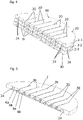
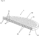
- FIG. 4 1 shows a third embodiment of the invention, in which a plurality of cells 2-1, 2-2, 2-3 are stacked one on top of the other.
- the three disk-shaped cells 2-i with a circular cross-section have an identical structure.
- the cells 2-i are similar to the cell 2 of the second embodiment and differ from the cell by Figure 1 and 2 in that the cells 2-i are penetrated by a plurality of slots 20 running in a straight line in one plane as flow channels for the working gas.
- the slit-shaped flow channels 20 run parallel to one another, but end in front of the edge of the cells 2-i, so that the cell 2 cannot fall apart.
- tubular cavities 6-i which have a cross-section in the form of an equilateral triangle with a right angle.
- the apex of the right-angled triangle points upwards, so that the two sides of the equilateral triangle extend upwards at a 45° angle.
- Cavities 6-i with a triangular cross-section can be easily produced using 3D printing.
- the cavities 6-i are connected to one another at the edge of the disc-shaped cells 2-i.
- a pressure equalization opening 8 connects the cavities 6-i with the area outside the cells 2-i.
- the cells 2-i have a plurality of alignment pins 30 on their upper side and corresponding alignment depressions 32 are arranged on the opposite side. Through these alignment elements 30, 32 is achieved that the slit-shaped flow channels 20 of the cells 6-i lying one above the other are aligned with one another, so that continuous flow channels result through the regenerator.
- a thermally insulating layer 34 is arranged between the individual cells 6 - i, through which the alignment pin 30 passes, so that the alignment pins can engage in the alignment openings 32 located above.
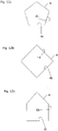
- FIG 5 shows schematically a fourth embodiment of the regenerator in the form of a disk-shaped cell 2, which differs from the cells 2-i according to 4 differs in that instead of a tubular cavity with a triangular cross section, two tubular cavities 6a and 6b are provided.
- the cross section of the tubular cavities 6a and 6b is also in the shape of a right-angled equilateral triangle. The right angle begins on the inside of the partition wall 4, which delimits the slit-shaped flow channels. This results in a partition 4 with a constant wall thickness between the flow channels 20 and the cavities 6-i. This leads to an improved heat transfer between the working gas in the flow channel 20 and the helium in the cavities 6a and 6b.
- the pressure equalization opening 8 connects the cavities 6a, 6b with the area outside the cell 2.
- FIG. 6 shows a fifth embodiment of the invention, which differs from the embodiment according to FIG figure 4 differs only in that the tubular cavities 6a, 6b are arranged with triangular cross section with the base of the right triangle towards the flow channels 20. Since the base is the length of the side of the equilateral triangle, this improves heat transfer.
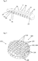
- FIG. 1 shows a regenerator 101 with a large number of cells 102 which are arranged in the form of a 3-dimensional matrix 103 with two layers of cells 102.
- FIG. The cells 102 are cubic and basically identical in construction. However, since the regenerator 101 fills a pipe cross section, the cells 102 inevitably have a different shape in the edge area.
- the individual cells 102 each comprise a cube-shaped cavity 106 with a heat-conducting shell 104 and a pressure equalization opening 108 in the form of a capillary. How out 8 can be seen, the individual cells are 102 arranged offset one behind the other in the direction of flow 112 of the working gas.
- the cells 102 lying next to one another are connected to one another by means of thermally conductive connecting elements 114 .
- the cells 102 lying one behind the other in the direction of flow 112 are connected to one another with thermally insulating or poorly conducting connecting elements 116 and form a flow channel 120.
- FIG 7 only two tiers of cells 102 are shown, while in 8 three layers of cells 102 are shown.
- the gas volume of the individual cavities 106 is approximately 1 mm 2
- the wall thickness of the shell 104 is approximately 0.2 mm.
- the distance between the individual cells 102 is approximately 0.2 mm.
- the total space requirement of a cell 102 is approximately 8 mm 3 .
- the regenerator 101 according to the invention is preferably used as a low-temperature regenerator section 242 in the coldest cold stage of a cryocooler.
- FIG 11 shows an eighth embodiment of the invention in the form of a disc-shaped cell 2, which is composed of a first and a second half-cell 50, 52, so that a cell 2 results analogously to the embodiments according to FIG figure 5 and 6 between the slit-shaped flow channels 20 has cuboid structures in cross-section.
- Both half-cells 50, 52 each have a plurality of first and second cavities 54 and 56 having a cross section of an isosceles triangle.
- the two half-cells 50, 52 can be produced using 3D printing.
- the two half-cells each have a flat side 58 and an uneven side 60 .
- the two uneven sides 60 have a complementary shape and when the two half-cells 50, 52 are assembled, the complementary uneven sides 60 of the two half-cells lie on top of each other.
- the regenerators with cells 2, each having two half-cells 50, 52 increases in the regenerators with cells 2, each having two half-cells 50, 52, the proportion of the cavity volume in the total volume of the regenerator. This makes the regenerator more efficient.
- the pressure equalization opening 8 is in the Figures 2 to 6 and 9 to 11 not marked but available. Since the cavities 6-i; 6′, 6a, 6b are connected to one another, the pressure equalization opening 8 can be provided at any point in the cells 2.
- Figures 12a, 12b and 12c show possible further cross-sectional shapes of the cavities 6 in the disk-shaped regenerators according to FIG Figures 3 to 6 and 11 that can be easily produced using 3D printing.
Landscapes
- Engineering & Computer Science (AREA)
- Physics & Mathematics (AREA)
- Mechanical Engineering (AREA)
- Thermal Sciences (AREA)
- General Engineering & Computer Science (AREA)
- Compressors, Vaccum Pumps And Other Relevant Systems (AREA)
- Heat-Exchange Devices With Radiators And Conduit Assemblies (AREA)
- Separation By Low-Temperature Treatments (AREA)
Description
Die Erfindung betrifft einen Regenerator für Kryo-Kühler mit Helium als Arbeitsgas gemäß Anspruch 1, ein Verfahren zur Herstellung eines solchen Regenerators nach Anspruch13 und 14 sowie einen mit einem solchen Regenerator versehenen KryoKühler nach Anspruch 15.The invention relates to a regenerator for cryocoolers with helium as the working gas according to claim 1, a method for producing such a regenerator according to claims 13 and 14 and a cryocooler provided with such a regenerator according to claim 15.
Periodisch betriebene Kryo-Kühler, wie z. B. Stirling-, Gifford-McMahon- und Pulsrohr-Kühler werden regeneratorisch betrieben. D. h. man nutzt die Wärmekapazität eines Materials aus, um die Kälte zu speichern bzw. um warmes Gas beim Eintritt in die Expansionskammer vor zu kühlen. Ein Problem hierbei ist, dass bei Temperaturen im Bereich 2K bis 20K die Wärmekapazität fast aller Materialien stark abnimmt. Damit ist es sehr schwer, Materialien zu finden, die im Bereich zwischen 2K und 20K eine ausreichend hohe Wärmekapazität aufweisen.
Helium wird häufig als Arbeitsgas bei Kryo-Kühler eingesetzt. Helium besitzt in dem Temperaturbereich von 2K bis 20K eine vergleichsweise hohe Wärmekapazität, die der Wärmekapazität von seltenen Erdverbindungen in diesem Temperaturbereich gleich kommt. Daher ist vorgeschlagen worden Helium als Regenerator-Material einzusetzen. Aus der
In dem Artikel "
Es ist daher Aufgabe der vorliegenden Erfindung einen im Vergleich zu Regeneratoren mit seltenen Erdverbindungen kostengünstigen Regenerator anzugeben, der Helium als Wärmespeichermaterial nutzt und dennoch einen einfachen Aufbau aufweist.It is therefore the object of the present invention to specify a regenerator which is inexpensive in comparison to regenerators with rare earth compounds and which uses helium as the heat storage material and nevertheless has a simple structure.
Die Lösung dieser Aufgabe erfolgt durch die Merkmale des Anspruch 1.This problem is solved by the features of claim 1.
Der Regenerator besteht im einfachsten Fall aus einer hohlen Zelle mit Wärme leitenden Zellwänden. Die Außenseite der Zellwände begrenzt wenigstens zum Teil einen Strömungskanal für das Arbeitsgas Helium. Der Hohlraum ist mit Helium als Wärmespeichermaterial gefüllt und ist über eine Druckausgleichsöffnung mit Außenseite der Zelle verbunden. Das Arbeitsgas Helium, umströmt die dosenförmige Zelle, wodurch über die Zellwände ein Wärmeübergang zwischen dem Arbeitsgas Helium außerhalb des Hohlraums und dem Helium innerhalb des Hohlraums stattfindet. Die Größe der Zelle(n) in Relation zu der Größe des Strömungskanals des Arbeitsgases ist so gewählt, dass sich zwischen der Hochdruckseite und der Niederdruckseite des Regenerators die gewünschten Druckdifferenzen bei einem möglichst geringen Totvolumen einstellen. Die Zellwände der Zelle weisen eine sehr geringe Wandstärke auf, sodass der gewünschte Wärmeaustausch erfolgen kann. Das Verhältnis von Volumen des oder der Hohlräume zu Öffnungsfläche bzw. Ausströmwiderstand der Druckausgleichsöffnung ist so gewählt, dass sich der Druck im Hohlraum oder in den Hohlräumen im Arbeitsfrequenzbereich des Kühlerbetriebs (ca. 1 bis 60 Hz) kaum oder zumindest nur wenig ändert. Diese Funktionsweise ist vergleichbar mit einem Kondensator bei hohen Frequenzen - dieser bekommt von der Änderung der Spannung quasi nichts mit, wenn die Kapazität hoch genug ist und die Spannungsänderung gering. Im typischen Anwendungsfall würde der Druck in der Zelle immer um den Mitteldruck des Kühlsystems, typischer Weise ca. 16 bar, schwanken. Der stabile Druck ist deshalb wichtig, da ansonsten das Volumen des oder der Hohlräume einen großen Beitrag zum "Totvolumen" wäre, wenn dessen Druck bei jeder Periode zwischen z. B. 8 und 24 bar schwanken würde, ohne dass es zur Kühlung beiträgt. Die Öffnungsfläche bzw. der Ausströmwiderstand der Druckausgleichsöffnung ist so gewählt, dass vor Inbetriebnahme des Regenerators und während der Anlaufphase aufgrund der herrschenden Druckverhältnisse Helium in den oder die Hohlräume eindringt. Durch den hohen Ausströmwiderstand der Druckausgleichsöffnung ergibt sich der vorstehend erläuterte "Kondensator-Effekt" während der Druckschwankungen im Bereich des Regenerators mit der Arbeitsfrequenz eines Kühlers. In der Anlaufphase sinkt die Temperatur des Arbeitsgases Helium und auch des Heliums in den Regeneratorhohlräumen. Folglich verringert sich das Volumen des Heliums und über die Druckausgleichsöffnung strömt weiter Helium in die Regeneratorhohlräume nach. D. h. während der Anlaufphase muss Helium nachgefüllt werden, bis sich die Arbeitstemperaturen und -drücke eingestellt haben. Ohne Druckausgleichsöffnung müssten die Hohlräume in der Zelle vorab mit Helium befüllt werden, was aufgrund der Drücke im Bereich von 16 bar im Arbeitsbereich des Kryo-Kühlers erheblich dickere Zellwände bedingen würde. Werden die Hohlkörper bei Umgebungstemperatur mit Helium befüllt, müssen aufgrund der geringeren Dichte von Helium bei Umgebungstemperatur noch wesentlich höhere Drücke für die Befüllung gewählt werden. Dies führt zu dickeren Zellwänden mit erheblich höheren Wärmedurchgangswiderstand. Durch die dickeren Zellwände würde einen Wärmedurchgangswiderstand der Zellwände so hoch, dass im Arbeitsfrequenzbereich von Kryo-Kühlern kaum mehr zu einem Wärmeaustausch zwischen dem Arbeitsgas Helium und dem Helium im Inneren des oder der Hohlräume kommen würde. Dies dürfte auch der Grund sein, dass kein Kryo-Kühler auf dem Markt ist, der einen Regenerator mit Helium in geschlossenen Hohlräumen einsetzt. Die Druckausgleichsöffnung hat erfindungsgemäß die Form einer Kapillare.In the simplest case, the regenerator consists of a hollow cell with heat-conducting cell walls. The outside of the cell walls at least partially delimits a flow channel for the working gas helium. The cavity is filled with helium as a heat storage material and is connected to the outside of the cell via a pressure equalization opening. The working gas, helium, flows around the can-shaped cell, as a result of which heat transfer takes place via the cell walls between the working gas helium outside the cavity and the helium inside the cavity. The size of the cell(s) in relation to the size of the flow channel of the working gas is selected in such a way that the desired pressure differences are set between the high-pressure side and the low-pressure side of the regenerator with the smallest possible dead volume. The cell walls of the cell are very thin, so that the desired heat exchange can take place. The ratio of the volume of the cavity or cavities to the opening area or outflow resistance of the pressure equalization opening is chosen so that the pressure in the cavity or cavities in the working frequency range of cooler operation (approx. 1 to 60 Hz) hardly changes, or at least only slightly. This mode of operation can be compared to a capacitor at high frequencies - it is virtually unaware of the change in voltage if the capacity is high enough and the voltage change is small. In a typical application, the pressure in the cell would always fluctuate around the medium pressure of the cooling system, typically around 16 bar. The stable pressure is important because otherwise the volume of the cavity or cavities would be a large contributor to the "dead volume" if its pressure was between e.g. B. 8 and 24 bar would fluctuate without it contributing to the cooling. The opening area or the outflow resistance of the pressure compensation opening is selected in such a way that before the regenerator is put into operation and during the start-up phase, helium penetrates into the cavity or cavities due to the prevailing pressure conditions. The high outflow resistance of the pressure equalization opening results in the "condenser effect" explained above during the Pressure fluctuations in the area of the regenerator with the working frequency of a cooler. During the start-up phase, the temperature of the working gas helium and also of the helium in the regenerator cavities decreases. As a result, the volume of helium is reduced and helium continues to flow into the regenerator cavities via the pressure equalization opening. i.e. During the start-up phase, helium must be refilled until the working temperatures and pressures have settled. Without a pressure equalization opening, the cavities in the cell would have to be filled with helium in advance, which would require significantly thicker cell walls due to the pressures in the range of 16 bar in the working area of the cryocooler. If the hollow bodies are filled with helium at ambient temperature, significantly higher pressures must be chosen for the filling due to the lower density of helium at ambient temperature. This leads to thicker cell walls with significantly higher thermal resistance. Due to the thicker cell walls, a heat transfer resistance of the cell walls would be so high that in the working frequency range of cryogenic coolers there would hardly be any heat exchange between the working gas helium and the helium inside the cavity or cavities. This may also be the reason that there is no cryo-cooler on the market that uses a regenerator with helium in closed cavities. According to the invention, the pressure equalization opening has the form of a capillary.
Die Zelle wird von Strömungskanälen durchsetzt, die von Zellwänden begrenzt sind. Hierdurch ergibt sich eine vergrößerte Wärmeaustauschfläche und somit ein verbesserter Wärmübergang zwischen dem Helium in den Hohlräumen und dem Arbeitsgas außen. Die Strömungskanäle sind vorzugsweise als Schlitze ausgebildet. Die Schlitze enden vor dem Rand der Zelle, sodass die Zelle nicht auseinanderfallen kann. Die Strömungskanäle sind als eine Mehrzahl von Schlitzen ausgebildet, die geradlinig und parallel zueinander verlaufen und vor dem Rand der Zelle enden, sodass die Zelle nicht auseinanderfallen kann. Ein umlaufender Kanal ist an dem Rand der Zelle ausgebildet, in den die mehrere miteinander verbundenen Hohlräume münden.The cell is penetrated by flow channels that are delimited by cell walls. This results in an enlarged heat exchange surface and thus improved heat transfer between the helium in the cavities and the working gas outside. The flow channels are preferably designed as slots. The slits end short of the edge of the cell, preventing the cell from falling apart. The flow channels are formed as a plurality of slots that are straight and parallel to each other and terminate short of the edge of the cell so that the cell cannot fall apart. A circumferential channel is formed at the edge of the cell into which the multiple interconnected cavities open.
Die schlitzförmigen Strömungskanäle für Arbeitsgas verlaufen vorzugsweise geradlinig und parallel zueinander, um zum einen den Strömungswiderstand zu minimieren und zum anderen, um die rohrförmigen Hohlräume zwischen den gleichförmig zu gestalten. Durch die Geradlinigkeit und die Parallelität ergibt sich auf einfache Weise zwischen zwei Strömungskanälen ein gleicher Abstand.The slit-shaped flow channels for working gas preferably run in a straight line and parallel to one another, on the one hand to minimize the flow resistance and on the other hand to uniformly close the tubular cavities between the shape. Due to the straightness and the parallelism, an equal distance is obtained in a simple manner between two flow channels.
Durch die runde Außenform des Regenerators lassen sie sich auf einfache Weise in die üblicherweise runden Querschnitte der Kryokühler einfügen. Dabei kann eine einzige Zelle, gegebenenfalls mit mehreren rohrförmigen Strukturen, die Form einer Scheibe haben. Alternativ können mehrere Zellen zu einer Scheibenform zusammengefügt werden. - Anspruch2.Due to the round outer shape of the regenerator, they can easily be inserted into the usually round cross-sections of cryocoolers. A single cell, optionally with a plurality of tubular structures, can have the shape of a disc. Alternatively, multiple cells can be assembled into a disk shape. - Claim2.
Durch die Hintereinanderanordnung nach Anspruch 3 erhöht sich die Wärmespeicherkapazität des Regenerators.The arrangement in a row according to claim 3 increases the heat storage capacity of the regenerator.
Durch eine thermische Isolierung zwischen in Strömungsrichtung des Arbeitsgases hintereinander angeordneten Zellen - Anspruch 4 - wird verhindert, dass zwischen den Hohlräumen in Strömungsrichtung des Arbeitsgases Wärme ausgetauscht wird. Ein solcher Wärmeaustausch in Strömungsrichtung des Arbeitsgases würde einen Kurzschluss des Regenerators bedeuten; ein Wärmeaustausch in Strömungsrichtung des Arbeitsgases trägt nicht zur Funktion des Regenerators bei. Die Dicke der thermisch isolierenden Schicht beträgt vorzugsweise zwischen 0,1mm und 0,5mm.Thermal insulation between cells arranged one behind the other in the direction of flow of the working gas - claim 4 - prevents heat from being exchanged between the cavities in the direction of flow of the working gas. Such a heat exchange in the flow direction of the working gas would mean a short circuit of the regenerator; a heat exchange in the flow direction of the working gas does not contribute to the function of the regenerator. The thickness of the thermally insulating layer is preferably between 0.1 mm and 0.5 mm.
Durch die Ausrichtelemente nach Anspruch 5 bis 7 wird die fluchtende Ausrichtung der Strömungskanäle aufeinander liegender Zellen vereinfacht. Die Ausrichtelemente sind z. B. Ausrichtzapfen, die eine konische oder pyramidenförmige Spitze aufweisen.The alignment elements according to claim 5 to 7 simplify the alignment of the flow channels of cells lying one on top of the other. The alignment elements are z. B. Alignment pins having a conical or pyramidal tip.
Die Form einer Kapillare bedeuted, dass die Querschnittsfläche der Öffnung im Vergleich zur Oberfläche des Hohlkörpers sehr klein ist.The shape of a capillary means that the cross-sectional area of the opening is very small compared to the surface area of the hollow body.
Die Druckausgleichsöffnung kann auch durch Undichtigkeiten bereitgestellt sein, die bei der Herstellung der Zellen auftreten - Anspruch 8.The pressure equalization opening can also be provided by leaks that occur during the manufacture of the cells -
Die Größe und damit die Durchlässigkeit der Druckausgleichsöffnung werden so gewählt, dass während eines Arbeitszyklus des Regenerators die Druckänderung in der Zelle maximal 20% und vorzugsweise maximal 10% beträgt. Es handelt sich hier um einen Optimierungsprozess. Je größer die Kapillare, desto größer ist der unerwünschte Stoffaustausch, desto größer sind die Druckschwankungen im Hohlraum der Zelle und umso schneller erfolgt das Eindringen des Heliums in die Hohlräume bei Inbetriebnahme des Regenerators. Je kleiner die Kapillare desto weniger Kompressionsarbeit muss verrichtet werden, aber desto länger dauert das Eindringen des Heliums in die Hohlräume bei Inbetriebnahme des Regenerators..The size and thus the permeability of the pressure equalization opening are chosen so that during a working cycle of the regenerator, the pressure change in the cell is a maximum of 20% and preferably a maximum of 10%. This is an optimization process. The larger the capillary, the greater the unwanted mass transfer, the greater the pressure fluctuations in the cell cavity and the faster the helium penetrates into the cavities when the regenerator is started up. The smaller the capillary, the less compression work has to be done, but the longer it takes for the helium to penetrate the cavities when the regenerator is started up.
Um den Wärmeaustausch zwischen dem Arbeitsgas Helium und dem in dem Hohlkörper befindlichen, Wärme speichernden Helium zu verbessern, sind die Oberflächen der Hohlkörper mit Verwirbelungsstrukturen versehen - Anspruch 9In order to improve the heat exchange between the working gas helium and the heat-storing helium located in the hollow body, the surfaces of the hollow bodies are provided with turbulence structures - claim 9
Die Querschnittsformen der rohrförmigen Hohlräume nach Anspruch 10 ermöglichen die Herstellung des Regenerators mittels 3D-Druck (Anspruch 14). Die Quaderoder Rechteckform der Querschnitte der Hohlräume ist für den Wärmeaustausch optimal. Zellen mit rohrförmigen Hohlräumen mit wenigstens einer schrägen Zellwand oder mit Dreiecksquerschnitt lassen sich leicht mittels 3D-Druck erzeugen. Mittels 3D-Druck können Strukturen mit vertikalen oder schrägen Zellwänden (Schrägen von 45° oder mehr) leicht hergestellt werden. Dies ist am einfachsten gewährleistet, wenn der Dreiecksquerschnitt der Hohlräume einen rechten Winkel aufweist. Auch geeignet ist ein rautenförmiger Querschnitt, ein fünfeckiger Querschnitt oder ein hausförmiger Querschnitt - Anspruch 10.The cross-sectional shapes of the tubular cavities according to claim 10 enable the manufacture of the regenerator by means of 3D printing (claim 14). The cuboid or rectangular shape of the cross sections of the cavities is optimal for heat exchange. Cells with tubular cavities with at least one sloping cell wall or with a triangular cross-section can be easily created using 3D printing. Using 3D printing, structures with vertical or sloping cell walls (slopes of 45° or more) can easily be produced. This is most easily ensured when the triangular cross section of the cavities has a right angle. A diamond-shaped cross-section, a pentagonal cross-section or a house-shaped cross-section is also suitable -
Für den optimalen Wärmetausch zwischen dem Helium in den rohrförmigen Hohlräumen und dem Arbeitsgas Helium außerhalb der Hohlräume sind zwischen den rohrförmigen Hohlräumen Strömungskanäle angeordnet - Anspruch 11.For the optimal heat exchange between the helium in the tubular cavities and the working gas helium outside of the cavities, flow channels are arranged between the tubular cavities - claim 11.
Durch die vorteilhafte Ausgestaltung nach Anspruch 12, bei der der scheibenförmige Regenerator aus einer oder mehreren scheibenförmigen Zellen besteht und jede Zelle jeweils zwei Halbzellen umfasst, wird erreicht, dass beide Halbzellen mittels 3D-Druck herstellbar sind. Gleichzeitig erhöht sich der Anteil des Volumens der Hohlräume - und damit des Heliums in den Hohlräumen - am Gesamtvolumen des Regenerators im Vergleich zu Regeneratoren, die nur einteilige Zellen aufweisen. Dies erhöht die Wärmespeicherfähigkeit des Regenerators oder der Regenerator kann bei gleicher Wärmekapazität kompakter ausgeführt werden.The advantageous embodiment according to
Bei 3D-Druck-Verfahren können quaderförmige Hohlräume oder ellipsoidförmige Hohlräume als Ganzes oder in zwei Schritten aus zwei Komponenten hergestellt werden - Anspruch 13 oder 14. Nach Anspruch 14 wird zunächst eine erste Komponente mit "offenen Hohlräumen" bzw. mit topfförmigen Vertiefungen erzeugt. Diese Vertiefungen werden dann in einem zweiten Schritt durch zweite Komponenten abgedeckt. Die ersten und zweiten Komponenten werden dauerhaft miteinander verbunden, z. B. durch Verklebung oder Verschweißung.In 3D printing processes, cuboid cavities or elliptical cavities can be produced from two components as a whole or in two steps - claim 13 or 14. According to claim 14, a first component with "open cavities" or with pot-shaped depressions is first produced. In a second step, these depressions are then covered by second components. The first and second components are permanently joined together, e.g. B. by gluing or welding.
Die Regeneratoren gemäß der vorliegenden Erfindung sind besonders für insbesondere für Stirling-, Gifford-McMahon- oder Pulsrohr-Kühler geeignet - Anspruch 15.The regenerators according to the present invention are particularly suitable for Stirling, Gifford-McMahon or pulse tube coolers in particular - claim 15.
Die Hohlkörper bestehen aus Metall und/oder und können aufgrund der Druckausgleichsöffnung gegenüber dem Stand der Technik sehr dünn ausgebildet werden, wodurch der Wärmeübergangswiderstand zwischen dem Helium im Inneren der Hohlräume und dem Arbeitsgas Helium außerhalb Hohlräume sinkt. Die Zellwände der Hohlräume weisen zumindest entlang der Strömungskanäle vorzugsweise eine konstante Dicke auf und liegen im Bereich zwischen 0,1mm und 0,5mm. Durch die konstante Wandstärke der Zellwände wird zwischen dem Arbeitsgas Helium in den Strömungskanälen und dem Helium in den Hohlräumen ein gleichmäßiger Wärmeübergang erreicht.The hollow bodies are made of metal and/or and can be made very thin compared to the prior art due to the pressure equalization opening, which reduces the heat transfer resistance between the helium inside the cavities and the helium working gas outside the cavities. The cell walls of the cavities preferably have a constant thickness, at least along the flow channels, and are in the range between 0.1 mm and 0.5 mm. Due to the constant wall thickness of the cell walls, a uniform heat transfer is achieved between the working gas helium in the flow channels and the helium in the cavities.
Der gesamte Regenerator weist in Strömungsrichtung des Arbeitsgases vorzugsweise eine Dicke von 5mm bis 100mm auf.The entire regenerator preferably has a thickness of 5 mm to 100 mm in the flow direction of the working gas.
Die übrigen Ansprüche beziehen sich auf weitere vorteilhafte Ausgestaltungen der Erfindung.The remaining claims relate to further advantageous configurations of the invention.
Nachfolgend werden bevorzugte Ausführungsformen der Erfindung anhand der Zeichnung beschrieben.Preferred embodiments of the invention are described below with reference to the drawing.
Es zeigt:
-
Fig. 1 eine Schnittdarstellung einer ersten Ausführungsform des Regenerators in einem Strömungskanal für Arbeitsgas, -
Fig. 2 eine Schnittdarstellung der ersten Ausführungsform entlang II - II inFig. 1 , -
Fig. 3a und 3b eine schematische Darstellung einer zweiten Ausführungsform, -
Fig. 4 eine schematische Darstellung einer dritten Ausführungsform, -
Fig. 5 eine schematische Darstellung einer vierten Ausführungsform, -
Fig. 6 eine schematische Darstellung einer fünften Ausführungsform, -
Fig. 7 eine sechste Ausführungsform, die nicht durch die beanspruchte Erfindung abgedeckt ist, in Form einer dreidimensionalen Matrixanordnung mit zwei Lagen von Zellen mit einem kreisringförmigen Außendurchmesser, -
Fig. 8 , die nicht durch die beanspruchte Erfindung abgedeckt ist, eine Detaildarstellung der Matrixanordnung mit drei Lagen von Zellen senkrecht zur Strömungsrichtung des Arbeitsgases betrachtet, -
Fig. 9 schematische Darstellungen zur Herstellung des Regenerators aus einer Schalenstruktur und einer Abdeckung gemäß einer siebten Ausführungsform,und 10 -
Fig. 11 eine achte Ausführungsform der Erfindung, die aus zwei mittels 3D-Druck hergestellten Strukturen besteht, -
Fig. 12a, 12b und 12c Beispiele für Querschnitte der Hohlräume mit dem wärmespeichernden Helium, die sich ohne weiteres mittels 3D-Druck herstellen lassen, -
Fig. 13 den typischen Aufbau eines Kryo-Kühlers in Form einer Pulsrohrkühlers mit zwei Kaltstufen, wobei die zweite Kaltstufe einen Tieftemperatur-Regenerator aufweist, und -
Fig. 14 den schematischen Aufbau eines Tieftemperatur-Regenerators nach dem Stand der Technik mit seltenen Erden in Form von Kügelchen.
-
1 a sectional view of a first embodiment of the regenerator in a flow channel for working gas, -
2 a sectional view of the first embodiment along II - II in1 , -
Figures 3a and 3b a schematic representation of a second embodiment, -
4 a schematic representation of a third embodiment, -
figure 5 a schematic representation of a fourth embodiment, -
6 a schematic representation of a fifth embodiment, -
7 a sixth embodiment, which is not covered by the claimed invention, in the form of a three-dimensional matrix arrangement with two layers of cells with a circular outer diameter, -
8 , which is not covered by the claimed invention, a detailed view of the matrix arrangement with three layers of cells perpendicular to the direction of flow of the working gas, -
Figures 9 and 10 schematic representations for the production of the regenerator from a shell structure and a cover according to a seventh embodiment, -
11 an eighth embodiment of the invention consisting of two structures produced by means of 3D printing, -
Figures 12a, 12b and 12c Examples of cross-sections of the cavities with the heat-storing helium, which can be easily produced using 3D printing, -
13 the typical structure of a cryocooler in the form of a pulse tube cooler with two cold stages, the second cold stage having a low-temperature regenerator, and -
14 the schematic structure of a low-temperature regenerator according to the prior art with rare earths in the form of small beads.
Die
Bei der Herstellung der scheibenförmigen Zelle 2 mittels 3D-Druck verbleiben zunächst eine oder zwei größere Öffnungen 22 durch die das lose 3D-Druck-Material noch dem 3D-Druck ausgeblasen werden kann. Diese Öffnungen werden anschließend verschlossen, so das lediglich eine oder mehrere Druckausgleichsöffnungen 8 in Form von Kapillaren verbleiben. Es lassen sich auch mehrere Zellen 2 in Strömungsrichtung des Arbeitsgases hintereinander anordnen, wodurch sich ein Regenerator mit höherer Leistung ergibt.When the disc-shaped
Die Hohlräume 6-i sind am Rand der scheibenförmigen Zellen 2-i miteinander verbunden. Eine Druckausgleichsöffnung 8 verbindet die Hohlräume 6-i mit dem Bereich außerhalb der Zellen 2-i. Die Zellen 2-i weisen auf ihrer Oberseite eine Mehrzahl von Ausrichtzapfen 30 auf und an der gegenüberliegenden Seite sind entsprechende Ausrichtvertiefungen 32 angeordnet. Durch diese Ausrichtelemente 30, 32 wird erreicht, dass die schlitzförmigen Strömungskanäle 20 der übereinander liegenden Zellen 6-i zueinander fluchten, sodass sich durch den Regenerator durchgehende Strömungskanäle ergeben. Zwischen den einzelnen Zellen 6-i ist jeweils eine thermisch-isolierende Schicht 34 angeordnet, die von dem Ausrichtzapfen 30 durchsetzt wird, sodass die Ausrichtzapfen in die darüber liegenden Ausrichtöffnungen 32 eingreifen können.The cavities 6-i are connected to one another at the edge of the disc-shaped cells 2-i. A
Der erfindungsgemäße Regenerator 101 wird vorzugsweise in der kältesten Kaltstufe eines Kryo-Kühlers als Tieftemperatur-Regeneratorabschnitt 242 eingesetzt.The
Analog der zweiten Ausführungsform nach
Die Druckausgleichsöffnung 8 ist in den
Die
- 11
- Regeneratorregenerator
- 22
- Zellecell
- 44
- Zellwandcell wall
- 4i4i
-
Innenseite der Zellwand 4Inside of the
cell wall 4 - 4a4a
-
Außenseite der Zellwand 4Outside of the
cell wall 4 - 6, 6-i, 6a, 6b6, 6-i, 6a, 6b
- Hohlraumcavity
- 88th
- Druckausgleichsöffnungpressure equalization opening
- 1010
- Strömungskanal für ArbeitsgasFlow channel for working gas
- 1212
- Ringspalt zwischen 2 und 10Annular gap between 2 and 10
- 2020
- schlitzförmige Strömungskanäle für Arbeitsgasslit-shaped flow channels for working gas
- 2222
- Ausblasöffnungenexhaust openings
- 2424
- umlaufender Verbindungskanalperipheral connecting channel
- 3030
- Ausrichtzapfenalignment pin
- 3232
- Ausrichtvertiefungenalignment dimples
- 3434
- thermisch isolierende Schichtthermally insulating layer
- 4040
- erste Komponente mit topfförmigen Vertiefungenfirst component with cup-shaped indentations
- 4242
- topfförmige Vertiefungenpot-shaped indentations
- 4444
- Abdeckungencovers
- 5050
- erste Halbzellefirst half cell
- 5252
- zweite Halbzellesecond half cell
- 5454
- erste Hohlräumefirst cavities
- 5656
- zweite Hohlräumesecond cavities
- 5858
- plane Seite von 50, 52flat side of 50, 52
- 6060
- uneben Seite von 50, 52uneven side of 50, 52
- 101101
- Regeneratorregenerator
- 102102
- Zellencells
- 103103
- Matrixanordnungmatrix arrangement
- 104104
- Hülle bzw. Zellwändeshell or cell walls
- 106106
- Hohlraumcavity
- 108108
- Druckausgleichsöffnungpressure equalization opening
- 112112
- Strömungsrichtung des ArbeitsgasesFlow direction of the working gas
- 114114
- thermisch leitende Verbindungselementethermally conductive fasteners
- 116116
- thermisch isolierende Verbindungselementethermally insulating fasteners
- 120120
- Strömungskanalflow channel
- 220220
- erste Kaltstufefirst cold stage
- 222222
- zweite Kaltstufesecond cold stage
- 224224
- erstes Pulsrohrfirst pulse tube
- 226226
- erster Regeneratorfirst regenerator
- 228228
- zweites Pulsrohrsecond pulse tube
- 230230
- zweiter Regeneratorsecond regenerator
- 232232
- Verbindungsmittellanyard
- 234234
- Arbeitsgasleitungenworking gas lines
- 236236
- Ventilevalves
- 238238
- Balastvolumenballast volume
- 240240
- erster Regeneratorabschnitt von 230first regenerator section of 230
- 242242
- Tieftemperatur-Regeneratorabschnitt von 230Cryogenic regenerator section of 230
- 244244
- Metallsiebe in 230Metal screens in 230
- 246246
- Kügelchen aus seltenen ErdverbindungenRare earth compound globules
Claims (15)
- Regenerator for cryo-coolers with helium as a working gas, comprisingat least one cell (2) with cell walls (4) including an exterior (4a) and an inner side (4i);wherein the cell walls (4) are at least partly heat conductive,the at least one cell (2) has a plurality of cavities (6; 6-i; 6a, 6b) connected with each other, which are surrounded by cell walls (4),the exterior (4a) of the cell walls (4) at least partly delimits a flow channel for the helium working gas;the at least one cell (2) has a pressure-equalizing opening (8), andthe at least one cell (2) includes flow channels (20) for the working gas, which are delimited by cell walls (4; 104), andthe cavities (6; 6-I; 6a, 6b) are filled with helium gas as a heat storage material,characterized in thatthe pressure-equalizing opening (8) is formed as a capillary, andthe flow channels (20) are formed as a plurality of slots extending rectilinearly and parallel to each other and end before the rim of the cell (2) so that the cell (2) cannot fall apart,a circumferential channel (24) is formed at the rim of the cell (2) into which the plurality of cavities (6; 6-i; 6a, 6b) connected with each other open.
- Regenerator according to one of the preceding claims, characterized in that the at least one cell (2) is formed as a disk with a round cross-section.
- Regenerator according to one of the preceding claims, characterized in that a plurality of cells (2) is arranged one behind the other in a flow direction of the working gas.
- Regenerator according to claim 3, characterized in that cells (2) arranged one behind the other in a flow direction of the working gas are separated from each other by a thermally insulating layer (34) including flow channels (20) for the working gas.
- Regenerator according to claim 4, characterized in that the cells (2) and the thermally insulating layer (34) each have alignment elements (30, 32), so that the flow channels (20) of the cells (2) and the thermally insulating layer or layers (34) are in alignment with each other.
- Regenerator according to claim 5, characterized in that the alignment elements include a plurality of alignment pins (30) on one side of the cells (2) and complementarily formed aligning recesses (32) on the other side of the cells.
- Regenerator according to claim 6, characterized in that the thermally insulating layer (34) includes alignment openings that are permeated by the alignment pins (30), so that the flow channels (20) for the working gas in the cells (2) and in the thermally insulating layer (34) are in alignment with each other.
- Regenerator according to one of the preceding claims, characterized in that the pressure-equalizing opening (8) results on account of leaks occurring during production of the regenerator.
- Regenerator according to one of the preceding claims, characterized in that the exterior of the cell walls (4) has turbulence structures in the flow channels (20) for the working gas.
- Regenerator according to one of the preceding claims, characterized in that the cavities (6-i; 6', 6a, 6b) have the shape of a tube and a cross-section in form of a triangle, a cross-section in form of a rectangle, or a cross-section with at least one slanting cell wall.
- Regenerator according to claim 10, characterized in that in a plurality of tube-shaped cavities (6-i, 6', 6a, 6b), flow channels (20) for the working gas are arranged per cell (2) between the tube-shaped cavities (6-i, 6', 6a, 6b).
- Regenerator according to one of the preceding claims, characterized in thatthe cells (2) are composed of two half cells (51, 50), each including a plurality of cavities with a cross-section in form of a triangle,that the tube-shaped cavities (6-i; 6'; 6a, 6b) are arranged between the flow channels (20) for the working gas,that each of the half cells has a flat side and an uneven side,that the uneven sides of the two half cells are formed complementarily to each other, andthat the two complementary uneven sides of the two half cells contact each other.
- Method for producing a regenerator according to one of the preceding claims, characterized in that the cell (2) is produced by 3D printing.
- Method for producing a regenerator according to one of claims 1 to 12, characterized in that the cell (2) is produced from at least two components (40, 44), which, after manufacture of the two components (40, 44), are connected to each other, and that at least one component (40) has a recess (42) forming at least part of the cavity/cavities (6').
- Cryo-cooler in form of a Stirling cooler, a Gifford-McMahon cooler or a pulse tube cooler including at least one regenerator (1), characterized in that the at least one regenerator (1) is a regenerator according to one of the preceding claims 1 to 12.
Applications Claiming Priority (3)
| Application Number | Priority Date | Filing Date | Title |
|---|---|---|---|
| DE202016106860.6U DE202016106860U1 (en) | 2016-12-08 | 2016-12-08 | Regenerator for cryocooler with helium as working gas |
| DE102017203506.4A DE102017203506A1 (en) | 2016-12-08 | 2017-03-03 | Regenerator for cryocooler with helium as working gas, a method for producing such a regenerator and a cryocooler with such a regenerator |
| PCT/EP2017/081750 WO2018104410A1 (en) | 2016-12-08 | 2017-12-06 | Regenerator for a cryo-cooler with helium as a working gas, a method for producing such a regenerator, and a cryo-cooler comprising such a regenerator |
Publications (2)
| Publication Number | Publication Date |
|---|---|
| EP3551947A1 EP3551947A1 (en) | 2019-10-16 |
| EP3551947B1 true EP3551947B1 (en) | 2022-09-14 |
Family
ID=61765518
Family Applications (1)
| Application Number | Title | Priority Date | Filing Date |
|---|---|---|---|
| EP17832047.9A Active EP3551947B1 (en) | 2016-12-08 | 2017-12-06 | Regenerator for a cryo-cooler with helium as a working gas, a method for producing such a regenerator, and a cryo-cooler comprising such a regenerator |
Country Status (6)
| Country | Link |
|---|---|
| US (1) | US11333406B2 (en) |
| EP (1) | EP3551947B1 (en) |
| JP (2) | JP2019536972A (en) |
| CN (1) | CN110050161B (en) |
| DE (2) | DE202016106860U1 (en) |
| WO (1) | WO2018104410A1 (en) |
Families Citing this family (3)
| Publication number | Priority date | Publication date | Assignee | Title |
|---|---|---|---|---|
| US10041747B2 (en) * | 2010-09-22 | 2018-08-07 | Raytheon Company | Heat exchanger with a glass body |
| FR3090840B1 (en) * | 2018-12-20 | 2021-01-08 | Univ Franche Comte | Regenerator and method of manufacturing such a regenerator |
| DE202021100084U1 (en) | 2021-01-11 | 2022-04-12 | Pressure Wave Systems Gmbh | Regenerator for cryo-cooler with helium as working gas and as heat storage material and a cryo-cooler with such a regenerator |
Family Cites Families (18)
| Publication number | Priority date | Publication date | Assignee | Title |
|---|---|---|---|---|
| US4359872A (en) * | 1981-09-15 | 1982-11-23 | North American Philips Corporation | Low temperature regenerators for cryogenic coolers |
| JPS62233688A (en) * | 1986-03-31 | 1987-10-14 | Aisin Seiki Co Ltd | Heat accumulator |
| JP2558810B2 (en) * | 1988-05-14 | 1996-11-27 | 住友電気工業株式会社 | Manufacturing method of sintered hollow parts |
| JP2697470B2 (en) * | 1992-04-08 | 1998-01-14 | ダイキン工業株式会社 | Regenerator and manufacturing method thereof |
| EP0637727A3 (en) * | 1993-08-05 | 1997-11-26 | Corning Incorporated | Cross-flow heat exchanger and method of forming |
| DE4401246A1 (en) * | 1994-01-18 | 1995-07-20 | Bosch Gmbh Robert | regenerator |
| JPH07318181A (en) * | 1994-05-20 | 1995-12-08 | Daikin Ind Ltd | Very low temperature freezer |
| US6131644A (en) * | 1998-03-31 | 2000-10-17 | Advanced Mobile Telecommunication Technology Inc. | Heat exchanger and method of producing the same |
| DE19924184A1 (en) | 1999-05-27 | 2000-11-30 | Christoph Heiden | Arrangement for using specific heat of helium gas in regenerators for low temperature gas refrigeration machines uses one of two types of helium gas regenerators with refrigeration machine |
| DE10318510A1 (en) * | 2003-04-24 | 2004-11-11 | Leybold Vakuum Gmbh | Heat storage medium |
| DE10319510B4 (en) | 2003-04-30 | 2016-12-29 | Zumtobel Lighting Gmbh | Busbar system for luminaires and locking element for use in a busbar system |
| DE102005007627A1 (en) * | 2004-02-19 | 2005-09-15 | Siemens Ag | A cryogenic refrigeration regenerator is filled with a higher thermal capacity material than the system gas pulsed through it |
| JP5468424B2 (en) * | 2010-03-12 | 2014-04-09 | 住友重機械工業株式会社 | Regenerator, regenerative refrigerator, cryopump, and refrigeration system |
| CN102812311B (en) * | 2010-03-19 | 2015-05-20 | 住友重机械工业株式会社 | Cold storage apparatus, gifford-mcmahon cooler, and pulse tube refrigerator |
| JP2014501868A (en) * | 2010-11-18 | 2014-01-23 | エタリム インコーポレイテッド | Stirling cycle converter device |
| JP5790989B2 (en) * | 2011-05-10 | 2015-10-07 | 独立行政法人国立高等専門学校機構 | Regenerator |
| CN104197591B (en) * | 2014-08-29 | 2016-11-30 | 浙江大学 | Use helium as the deep hypothermia regenerator of backheat medium and vascular refrigerator thereof |
| JP6185954B2 (en) * | 2015-03-31 | 2017-08-23 | ミネベアミツミ株式会社 | Spherical plain bearing and manufacturing method thereof |
-
2016
- 2016-12-08 DE DE202016106860.6U patent/DE202016106860U1/en active Active
-
2017
- 2017-03-03 DE DE102017203506.4A patent/DE102017203506A1/en active Pending
- 2017-12-06 JP JP2019526323A patent/JP2019536972A/en active Pending
- 2017-12-06 WO PCT/EP2017/081750 patent/WO2018104410A1/en unknown
- 2017-12-06 EP EP17832047.9A patent/EP3551947B1/en active Active
- 2017-12-06 CN CN201780074908.9A patent/CN110050161B/en active Active
-
2019
- 2019-06-08 US US16/435,477 patent/US11333406B2/en active Active
-
2022
- 2022-03-31 JP JP2022057805A patent/JP2022084912A/en active Pending
Also Published As
| Publication number | Publication date |
|---|---|
| WO2018104410A1 (en) | 2018-06-14 |
| US20190323737A1 (en) | 2019-10-24 |
| CN110050161B (en) | 2021-06-04 |
| DE202016106860U1 (en) | 2018-03-09 |
| EP3551947A1 (en) | 2019-10-16 |
| US11333406B2 (en) | 2022-05-17 |
| JP2019536972A (en) | 2019-12-19 |
| CN110050161A (en) | 2019-07-23 |
| DE102017203506A1 (en) | 2018-06-14 |
| US20220057114A9 (en) | 2022-02-24 |
| JP2022084912A (en) | 2022-06-07 |
Similar Documents
| Publication | Publication Date | Title |
|---|---|---|
| EP3551947B1 (en) | Regenerator for a cryo-cooler with helium as a working gas, a method for producing such a regenerator, and a cryo-cooler comprising such a regenerator | |
| EP2126495B1 (en) | Refrigerating appliance | |
| EP0122429B1 (en) | Composite material shaped as bars, tubes, strips, sheets or plates with reversible thermomechanical properties, and process for their manufacture | |
| DE112004002637T5 (en) | Brazed plate heat exchanger and transcritical cooling system | |
| DE4425524C2 (en) | Cooling device with a regenerator | |
| DE102010011500A1 (en) | Regenerative cooling device | |
| DE3873932T2 (en) | FILLED BODY TO RECEIVE ENERGY STORAGE MATERIAL WITH HIGH, LATEN MELT CRYSTALIZATION HEAT. | |
| AT514226B1 (en) | Piston engine and method for its operation | |
| CH654402A5 (en) | DISPLACEMENT FOR REFRIGERATORS. | |
| EP1616137A1 (en) | Heat-storing medium | |
| DE102012110701A1 (en) | Heat exchanger for a refrigerant circuit | |
| DE112004002839T5 (en) | Device for heat transport and method for its production | |
| DE3812427A1 (en) | METHOD FOR PRODUCING A REGENERATOR FOR A DEEP-TEMPERATURE REFRIGERATOR AND REGENERATOR PRODUCED BY THIS METHOD | |
| DE102004002252A1 (en) | Heat exchanger for vehicles | |
| DE69806683T3 (en) | Multi-tube heat exchanger | |
| DE202022101563U1 (en) | Kit for a heat exchanger | |
| DE29520864U1 (en) | regenerator | |
| DE4432340C1 (en) | Method for producing an evaporator for a compressor cooling unit | |
| EP2926073B1 (en) | Heat exchanger | |
| DE102004003325A1 (en) | Coaxial heat exchanger, in particular, for a vehicle heating/ventilating and/or air-conditioning plant comprises at least one structure whose wall thickness with respect to at least one of its other structures is reduced | |
| EP4275002A1 (en) | Regenerator for a cryo-cooler with helium as a working gas and as a heat-storing material, method for producing such a regenerator, and cryo-cooler with such a regenerator | |
| DE112013005720T5 (en) | Compact heat exchanger for a heat pump | |
| DE1514260C3 (en) | Method for the production of a housing base for a semiconductor device | |
| DE19628205C2 (en) | Device for carrying out a cooling process using low-boiling gases according to the patent 195 25 638 | |
| DE102014208254A1 (en) | Latent heat storage |
Legal Events
| Date | Code | Title | Description |
|---|---|---|---|
| STAA | Information on the status of an ep patent application or granted ep patent |
Free format text: STATUS: UNKNOWN |
|
| STAA | Information on the status of an ep patent application or granted ep patent |
Free format text: STATUS: THE INTERNATIONAL PUBLICATION HAS BEEN MADE |
|
| PUAI | Public reference made under article 153(3) epc to a published international application that has entered the european phase |
Free format text: ORIGINAL CODE: 0009012 |
|
| STAA | Information on the status of an ep patent application or granted ep patent |
Free format text: STATUS: REQUEST FOR EXAMINATION WAS MADE |
|
| 17P | Request for examination filed |
Effective date: 20190515 |
|
| AK | Designated contracting states |
Kind code of ref document: A1 Designated state(s): AL AT BE BG CH CY CZ DE DK EE ES FI FR GB GR HR HU IE IS IT LI LT LU LV MC MK MT NL NO PL PT RO RS SE SI SK SM TR |
|
| AX | Request for extension of the european patent |
Extension state: BA ME |
|
| DAV | Request for validation of the european patent (deleted) | ||
| DAX | Request for extension of the european patent (deleted) | ||
| STAA | Information on the status of an ep patent application or granted ep patent |
Free format text: STATUS: EXAMINATION IS IN PROGRESS |
|
| 17Q | First examination report despatched |
Effective date: 20200414 |
|
| STAA | Information on the status of an ep patent application or granted ep patent |
Free format text: STATUS: EXAMINATION IS IN PROGRESS |
|
| GRAP | Despatch of communication of intention to grant a patent |
Free format text: ORIGINAL CODE: EPIDOSNIGR1 |
|
| STAA | Information on the status of an ep patent application or granted ep patent |
Free format text: STATUS: GRANT OF PATENT IS INTENDED |
|
| INTG | Intention to grant announced |
Effective date: 20220404 |
|
| GRAS | Grant fee paid |
Free format text: ORIGINAL CODE: EPIDOSNIGR3 |
|
| GRAA | (expected) grant |
Free format text: ORIGINAL CODE: 0009210 |
|
| STAA | Information on the status of an ep patent application or granted ep patent |
Free format text: STATUS: THE PATENT HAS BEEN GRANTED |
|
| RIN1 | Information on inventor provided before grant (corrected) |
Inventor name: HOEHNE, JENS |
|
| RIN1 | Information on inventor provided before grant (corrected) |
Inventor name: HOEHNE, JENS, DR. |
|
| AK | Designated contracting states |
Kind code of ref document: B1 Designated state(s): AL AT BE BG CH CY CZ DE DK EE ES FI FR GB GR HR HU IE IS IT LI LT LU LV MC MK MT NL NO PL PT RO RS SE SI SK SM TR |
|
| REG | Reference to a national code |
Ref country code: GB Ref legal event code: FG4D Free format text: NOT ENGLISH |
|
| REG | Reference to a national code |
Ref country code: CH Ref legal event code: EP |
|
| REG | Reference to a national code |
Ref country code: DE Ref legal event code: R096 Ref document number: 502017013820 Country of ref document: DE |
|
| REG | Reference to a national code |
Ref country code: IE Ref legal event code: FG4D Free format text: LANGUAGE OF EP DOCUMENT: GERMAN |
|
| REG | Reference to a national code |
Ref country code: AT Ref legal event code: REF Ref document number: 1518929 Country of ref document: AT Kind code of ref document: T Effective date: 20221015 |
|
| REG | Reference to a national code |
Ref country code: LT Ref legal event code: MG9D |
|
| REG | Reference to a national code |
Ref country code: NL Ref legal event code: MP Effective date: 20220914 |
|
| PG25 | Lapsed in a contracting state [announced via postgrant information from national office to epo] |
Ref country code: SE Free format text: LAPSE BECAUSE OF FAILURE TO SUBMIT A TRANSLATION OF THE DESCRIPTION OR TO PAY THE FEE WITHIN THE PRESCRIBED TIME-LIMIT Effective date: 20220914 Ref country code: RS Free format text: LAPSE BECAUSE OF FAILURE TO SUBMIT A TRANSLATION OF THE DESCRIPTION OR TO PAY THE FEE WITHIN THE PRESCRIBED TIME-LIMIT Effective date: 20220914 Ref country code: NO Free format text: LAPSE BECAUSE OF FAILURE TO SUBMIT A TRANSLATION OF THE DESCRIPTION OR TO PAY THE FEE WITHIN THE PRESCRIBED TIME-LIMIT Effective date: 20221214 Ref country code: LV Free format text: LAPSE BECAUSE OF FAILURE TO SUBMIT A TRANSLATION OF THE DESCRIPTION OR TO PAY THE FEE WITHIN THE PRESCRIBED TIME-LIMIT Effective date: 20220914 Ref country code: LT Free format text: LAPSE BECAUSE OF FAILURE TO SUBMIT A TRANSLATION OF THE DESCRIPTION OR TO PAY THE FEE WITHIN THE PRESCRIBED TIME-LIMIT Effective date: 20220914 Ref country code: FI Free format text: LAPSE BECAUSE OF FAILURE TO SUBMIT A TRANSLATION OF THE DESCRIPTION OR TO PAY THE FEE WITHIN THE PRESCRIBED TIME-LIMIT Effective date: 20220914 |
|
| PG25 | Lapsed in a contracting state [announced via postgrant information from national office to epo] |
Ref country code: HR Free format text: LAPSE BECAUSE OF FAILURE TO SUBMIT A TRANSLATION OF THE DESCRIPTION OR TO PAY THE FEE WITHIN THE PRESCRIBED TIME-LIMIT Effective date: 20220914 Ref country code: GR Free format text: LAPSE BECAUSE OF FAILURE TO SUBMIT A TRANSLATION OF THE DESCRIPTION OR TO PAY THE FEE WITHIN THE PRESCRIBED TIME-LIMIT Effective date: 20221215 |
|
| PG25 | Lapsed in a contracting state [announced via postgrant information from national office to epo] |
Ref country code: SM Free format text: LAPSE BECAUSE OF FAILURE TO SUBMIT A TRANSLATION OF THE DESCRIPTION OR TO PAY THE FEE WITHIN THE PRESCRIBED TIME-LIMIT Effective date: 20220914 Ref country code: RO Free format text: LAPSE BECAUSE OF FAILURE TO SUBMIT A TRANSLATION OF THE DESCRIPTION OR TO PAY THE FEE WITHIN THE PRESCRIBED TIME-LIMIT Effective date: 20220914 Ref country code: PT Free format text: LAPSE BECAUSE OF FAILURE TO SUBMIT A TRANSLATION OF THE DESCRIPTION OR TO PAY THE FEE WITHIN THE PRESCRIBED TIME-LIMIT Effective date: 20230116 Ref country code: ES Free format text: LAPSE BECAUSE OF FAILURE TO SUBMIT A TRANSLATION OF THE DESCRIPTION OR TO PAY THE FEE WITHIN THE PRESCRIBED TIME-LIMIT Effective date: 20220914 Ref country code: CZ Free format text: LAPSE BECAUSE OF FAILURE TO SUBMIT A TRANSLATION OF THE DESCRIPTION OR TO PAY THE FEE WITHIN THE PRESCRIBED TIME-LIMIT Effective date: 20220914 |
|
| PG25 | Lapsed in a contracting state [announced via postgrant information from national office to epo] |
Ref country code: SK Free format text: LAPSE BECAUSE OF FAILURE TO SUBMIT A TRANSLATION OF THE DESCRIPTION OR TO PAY THE FEE WITHIN THE PRESCRIBED TIME-LIMIT Effective date: 20220914 Ref country code: PL Free format text: LAPSE BECAUSE OF FAILURE TO SUBMIT A TRANSLATION OF THE DESCRIPTION OR TO PAY THE FEE WITHIN THE PRESCRIBED TIME-LIMIT Effective date: 20220914 Ref country code: IS Free format text: LAPSE BECAUSE OF FAILURE TO SUBMIT A TRANSLATION OF THE DESCRIPTION OR TO PAY THE FEE WITHIN THE PRESCRIBED TIME-LIMIT Effective date: 20230114 Ref country code: EE Free format text: LAPSE BECAUSE OF FAILURE TO SUBMIT A TRANSLATION OF THE DESCRIPTION OR TO PAY THE FEE WITHIN THE PRESCRIBED TIME-LIMIT Effective date: 20220914 |
|
| REG | Reference to a national code |
Ref country code: DE Ref legal event code: R097 Ref document number: 502017013820 Country of ref document: DE |
|
| PG25 | Lapsed in a contracting state [announced via postgrant information from national office to epo] |
Ref country code: NL Free format text: LAPSE BECAUSE OF FAILURE TO SUBMIT A TRANSLATION OF THE DESCRIPTION OR TO PAY THE FEE WITHIN THE PRESCRIBED TIME-LIMIT Effective date: 20220914 Ref country code: AL Free format text: LAPSE BECAUSE OF FAILURE TO SUBMIT A TRANSLATION OF THE DESCRIPTION OR TO PAY THE FEE WITHIN THE PRESCRIBED TIME-LIMIT Effective date: 20220914 |
|
| PLBE | No opposition filed within time limit |
Free format text: ORIGINAL CODE: 0009261 |
|
| STAA | Information on the status of an ep patent application or granted ep patent |
Free format text: STATUS: NO OPPOSITION FILED WITHIN TIME LIMIT |
|
| PG25 | Lapsed in a contracting state [announced via postgrant information from national office to epo] |
Ref country code: DK Free format text: LAPSE BECAUSE OF FAILURE TO SUBMIT A TRANSLATION OF THE DESCRIPTION OR TO PAY THE FEE WITHIN THE PRESCRIBED TIME-LIMIT Effective date: 20220914 |
|
| REG | Reference to a national code |
Ref country code: CH Ref legal event code: PL |
|
| 26N | No opposition filed |
Effective date: 20230615 |
|
| REG | Reference to a national code |
Ref country code: BE Ref legal event code: MM Effective date: 20221231 |
|
| PG25 | Lapsed in a contracting state [announced via postgrant information from national office to epo] |
Ref country code: SI Free format text: LAPSE BECAUSE OF FAILURE TO SUBMIT A TRANSLATION OF THE DESCRIPTION OR TO PAY THE FEE WITHIN THE PRESCRIBED TIME-LIMIT Effective date: 20220914 Ref country code: LU Free format text: LAPSE BECAUSE OF NON-PAYMENT OF DUE FEES Effective date: 20221206 |
|
| PG25 | Lapsed in a contracting state [announced via postgrant information from national office to epo] |
Ref country code: LI Free format text: LAPSE BECAUSE OF NON-PAYMENT OF DUE FEES Effective date: 20221231 Ref country code: IE Free format text: LAPSE BECAUSE OF NON-PAYMENT OF DUE FEES Effective date: 20221206 Ref country code: CH Free format text: LAPSE BECAUSE OF NON-PAYMENT OF DUE FEES Effective date: 20221231 |
|
| PG25 | Lapsed in a contracting state [announced via postgrant information from national office to epo] |
Ref country code: BE Free format text: LAPSE BECAUSE OF NON-PAYMENT OF DUE FEES Effective date: 20221231 |
|
| PGFP | Annual fee paid to national office [announced via postgrant information from national office to epo] |
Ref country code: GB Payment date: 20231220 Year of fee payment: 7 |
|
| PGFP | Annual fee paid to national office [announced via postgrant information from national office to epo] |
Ref country code: FR Payment date: 20231220 Year of fee payment: 7 Ref country code: DE Payment date: 20231110 Year of fee payment: 7 |
|
| REG | Reference to a national code |
Ref country code: AT Ref legal event code: MM01 Ref document number: 1518929 Country of ref document: AT Kind code of ref document: T Effective date: 20221206 |
|
| PG25 | Lapsed in a contracting state [announced via postgrant information from national office to epo] |
Ref country code: HU Free format text: LAPSE BECAUSE OF FAILURE TO SUBMIT A TRANSLATION OF THE DESCRIPTION OR TO PAY THE FEE WITHIN THE PRESCRIBED TIME-LIMIT; INVALID AB INITIO Effective date: 20171206 |
|
| PG25 | Lapsed in a contracting state [announced via postgrant information from national office to epo] |
Ref country code: AT Free format text: LAPSE BECAUSE OF NON-PAYMENT OF DUE FEES Effective date: 20221206 |
|
| PG25 | Lapsed in a contracting state [announced via postgrant information from national office to epo] |
Ref country code: CY Free format text: LAPSE BECAUSE OF FAILURE TO SUBMIT A TRANSLATION OF THE DESCRIPTION OR TO PAY THE FEE WITHIN THE PRESCRIBED TIME-LIMIT Effective date: 20220914 Ref country code: AT Free format text: LAPSE BECAUSE OF NON-PAYMENT OF DUE FEES Effective date: 20221206 |
|
| PG25 | Lapsed in a contracting state [announced via postgrant information from national office to epo] |
Ref country code: MK Free format text: LAPSE BECAUSE OF FAILURE TO SUBMIT A TRANSLATION OF THE DESCRIPTION OR TO PAY THE FEE WITHIN THE PRESCRIBED TIME-LIMIT Effective date: 20220914 Ref country code: IT Free format text: LAPSE BECAUSE OF FAILURE TO SUBMIT A TRANSLATION OF THE DESCRIPTION OR TO PAY THE FEE WITHIN THE PRESCRIBED TIME-LIMIT Effective date: 20220914 |
|
| PG25 | Lapsed in a contracting state [announced via postgrant information from national office to epo] |
Ref country code: MC Free format text: LAPSE BECAUSE OF FAILURE TO SUBMIT A TRANSLATION OF THE DESCRIPTION OR TO PAY THE FEE WITHIN THE PRESCRIBED TIME-LIMIT Effective date: 20220914 |
|
| PG25 | Lapsed in a contracting state [announced via postgrant information from national office to epo] |
Ref country code: MC Free format text: LAPSE BECAUSE OF FAILURE TO SUBMIT A TRANSLATION OF THE DESCRIPTION OR TO PAY THE FEE WITHIN THE PRESCRIBED TIME-LIMIT Effective date: 20220914 |
|
| PG25 | Lapsed in a contracting state [announced via postgrant information from national office to epo] |
Ref country code: BG Free format text: LAPSE BECAUSE OF FAILURE TO SUBMIT A TRANSLATION OF THE DESCRIPTION OR TO PAY THE FEE WITHIN THE PRESCRIBED TIME-LIMIT Effective date: 20220914 |
|
| PG25 | Lapsed in a contracting state [announced via postgrant information from national office to epo] |
Ref country code: MT Free format text: LAPSE BECAUSE OF FAILURE TO SUBMIT A TRANSLATION OF THE DESCRIPTION OR TO PAY THE FEE WITHIN THE PRESCRIBED TIME-LIMIT Effective date: 20220914 |