EP3551925B1 - Hydrogen refueling system - Google Patents
Hydrogen refueling system Download PDFInfo
- Publication number
- EP3551925B1 EP3551925B1 EP16820368.5A EP16820368A EP3551925B1 EP 3551925 B1 EP3551925 B1 EP 3551925B1 EP 16820368 A EP16820368 A EP 16820368A EP 3551925 B1 EP3551925 B1 EP 3551925B1
- Authority
- EP
- European Patent Office
- Prior art keywords
- temperature
- refueling
- heat exchanger
- cryogenic fluid
- vehicle
- Prior art date
- Legal status (The legal status is an assumption and is not a legal conclusion. Google has not performed a legal analysis and makes no representation as to the accuracy of the status listed.)
- Active
Links
Images


Classifications
-
- F—MECHANICAL ENGINEERING; LIGHTING; HEATING; WEAPONS; BLASTING
- F17—STORING OR DISTRIBUTING GASES OR LIQUIDS
- F17C—VESSELS FOR CONTAINING OR STORING COMPRESSED, LIQUEFIED OR SOLIDIFIED GASES; FIXED-CAPACITY GAS-HOLDERS; FILLING VESSELS WITH, OR DISCHARGING FROM VESSELS, COMPRESSED, LIQUEFIED, OR SOLIDIFIED GASES
- F17C5/00—Methods or apparatus for filling containers with liquefied, solidified, or compressed gases under pressures
- F17C5/002—Automated filling apparatus
- F17C5/007—Automated filling apparatus for individual gas tanks or containers, e.g. in vehicles
-
- F—MECHANICAL ENGINEERING; LIGHTING; HEATING; WEAPONS; BLASTING
- F17—STORING OR DISTRIBUTING GASES OR LIQUIDS
- F17C—VESSELS FOR CONTAINING OR STORING COMPRESSED, LIQUEFIED OR SOLIDIFIED GASES; FIXED-CAPACITY GAS-HOLDERS; FILLING VESSELS WITH, OR DISCHARGING FROM VESSELS, COMPRESSED, LIQUEFIED, OR SOLIDIFIED GASES
- F17C13/00—Details of vessels or of the filling or discharging of vessels
- F17C13/02—Special adaptations of indicating, measuring, or monitoring equipment
- F17C13/025—Special adaptations of indicating, measuring, or monitoring equipment having the pressure as the parameter
-
- F—MECHANICAL ENGINEERING; LIGHTING; HEATING; WEAPONS; BLASTING
- F17—STORING OR DISTRIBUTING GASES OR LIQUIDS
- F17C—VESSELS FOR CONTAINING OR STORING COMPRESSED, LIQUEFIED OR SOLIDIFIED GASES; FIXED-CAPACITY GAS-HOLDERS; FILLING VESSELS WITH, OR DISCHARGING FROM VESSELS, COMPRESSED, LIQUEFIED, OR SOLIDIFIED GASES
- F17C2205/00—Vessel construction, in particular mounting arrangements, attachments or identifications means
- F17C2205/03—Fluid connections, filters, valves, closure means or other attachments
- F17C2205/0302—Fittings, valves, filters, or components in connection with the gas storage device
- F17C2205/0323—Valves
- F17C2205/0326—Valves electrically actuated
-
- F—MECHANICAL ENGINEERING; LIGHTING; HEATING; WEAPONS; BLASTING
- F17—STORING OR DISTRIBUTING GASES OR LIQUIDS
- F17C—VESSELS FOR CONTAINING OR STORING COMPRESSED, LIQUEFIED OR SOLIDIFIED GASES; FIXED-CAPACITY GAS-HOLDERS; FILLING VESSELS WITH, OR DISCHARGING FROM VESSELS, COMPRESSED, LIQUEFIED, OR SOLIDIFIED GASES
- F17C2221/00—Handled fluid, in particular type of fluid
- F17C2221/01—Pure fluids
- F17C2221/012—Hydrogen
-
- F—MECHANICAL ENGINEERING; LIGHTING; HEATING; WEAPONS; BLASTING
- F17—STORING OR DISTRIBUTING GASES OR LIQUIDS
- F17C—VESSELS FOR CONTAINING OR STORING COMPRESSED, LIQUEFIED OR SOLIDIFIED GASES; FIXED-CAPACITY GAS-HOLDERS; FILLING VESSELS WITH, OR DISCHARGING FROM VESSELS, COMPRESSED, LIQUEFIED, OR SOLIDIFIED GASES
- F17C2223/00—Handled fluid before transfer, i.e. state of fluid when stored in the vessel or before transfer from the vessel
- F17C2223/01—Handled fluid before transfer, i.e. state of fluid when stored in the vessel or before transfer from the vessel characterised by the phase
- F17C2223/0107—Single phase
- F17C2223/0123—Single phase gaseous, e.g. CNG, GNC
-
- F—MECHANICAL ENGINEERING; LIGHTING; HEATING; WEAPONS; BLASTING
- F17—STORING OR DISTRIBUTING GASES OR LIQUIDS
- F17C—VESSELS FOR CONTAINING OR STORING COMPRESSED, LIQUEFIED OR SOLIDIFIED GASES; FIXED-CAPACITY GAS-HOLDERS; FILLING VESSELS WITH, OR DISCHARGING FROM VESSELS, COMPRESSED, LIQUEFIED, OR SOLIDIFIED GASES
- F17C2223/00—Handled fluid before transfer, i.e. state of fluid when stored in the vessel or before transfer from the vessel
- F17C2223/03—Handled fluid before transfer, i.e. state of fluid when stored in the vessel or before transfer from the vessel characterised by the pressure level
- F17C2223/036—Very high pressure (>80 bar)
-
- F—MECHANICAL ENGINEERING; LIGHTING; HEATING; WEAPONS; BLASTING
- F17—STORING OR DISTRIBUTING GASES OR LIQUIDS
- F17C—VESSELS FOR CONTAINING OR STORING COMPRESSED, LIQUEFIED OR SOLIDIFIED GASES; FIXED-CAPACITY GAS-HOLDERS; FILLING VESSELS WITH, OR DISCHARGING FROM VESSELS, COMPRESSED, LIQUEFIED, OR SOLIDIFIED GASES
- F17C2227/00—Transfer of fluids, i.e. method or means for transferring the fluid; Heat exchange with the fluid
- F17C2227/03—Heat exchange with the fluid
- F17C2227/0302—Heat exchange with the fluid by heating
- F17C2227/0309—Heat exchange with the fluid by heating using another fluid
- F17C2227/0323—Heat exchange with the fluid by heating using another fluid in a closed loop
-
- F—MECHANICAL ENGINEERING; LIGHTING; HEATING; WEAPONS; BLASTING
- F17—STORING OR DISTRIBUTING GASES OR LIQUIDS
- F17C—VESSELS FOR CONTAINING OR STORING COMPRESSED, LIQUEFIED OR SOLIDIFIED GASES; FIXED-CAPACITY GAS-HOLDERS; FILLING VESSELS WITH, OR DISCHARGING FROM VESSELS, COMPRESSED, LIQUEFIED, OR SOLIDIFIED GASES
- F17C2250/00—Accessories; Control means; Indicating, measuring or monitoring of parameters
- F17C2250/03—Control means
- F17C2250/032—Control means using computers
-
- F—MECHANICAL ENGINEERING; LIGHTING; HEATING; WEAPONS; BLASTING
- F17—STORING OR DISTRIBUTING GASES OR LIQUIDS
- F17C—VESSELS FOR CONTAINING OR STORING COMPRESSED, LIQUEFIED OR SOLIDIFIED GASES; FIXED-CAPACITY GAS-HOLDERS; FILLING VESSELS WITH, OR DISCHARGING FROM VESSELS, COMPRESSED, LIQUEFIED, OR SOLIDIFIED GASES
- F17C2250/00—Accessories; Control means; Indicating, measuring or monitoring of parameters
- F17C2250/04—Indicating or measuring of parameters as input values
- F17C2250/0404—Parameters indicated or measured
- F17C2250/043—Pressure
-
- F—MECHANICAL ENGINEERING; LIGHTING; HEATING; WEAPONS; BLASTING
- F17—STORING OR DISTRIBUTING GASES OR LIQUIDS
- F17C—VESSELS FOR CONTAINING OR STORING COMPRESSED, LIQUEFIED OR SOLIDIFIED GASES; FIXED-CAPACITY GAS-HOLDERS; FILLING VESSELS WITH, OR DISCHARGING FROM VESSELS, COMPRESSED, LIQUEFIED, OR SOLIDIFIED GASES
- F17C2250/00—Accessories; Control means; Indicating, measuring or monitoring of parameters
- F17C2250/04—Indicating or measuring of parameters as input values
- F17C2250/0404—Parameters indicated or measured
- F17C2250/0439—Temperature
-
- F—MECHANICAL ENGINEERING; LIGHTING; HEATING; WEAPONS; BLASTING
- F17—STORING OR DISTRIBUTING GASES OR LIQUIDS
- F17C—VESSELS FOR CONTAINING OR STORING COMPRESSED, LIQUEFIED OR SOLIDIFIED GASES; FIXED-CAPACITY GAS-HOLDERS; FILLING VESSELS WITH, OR DISCHARGING FROM VESSELS, COMPRESSED, LIQUEFIED, OR SOLIDIFIED GASES
- F17C2250/00—Accessories; Control means; Indicating, measuring or monitoring of parameters
- F17C2250/04—Indicating or measuring of parameters as input values
- F17C2250/0404—Parameters indicated or measured
- F17C2250/0478—Position or presence
-
- F—MECHANICAL ENGINEERING; LIGHTING; HEATING; WEAPONS; BLASTING
- F17—STORING OR DISTRIBUTING GASES OR LIQUIDS
- F17C—VESSELS FOR CONTAINING OR STORING COMPRESSED, LIQUEFIED OR SOLIDIFIED GASES; FIXED-CAPACITY GAS-HOLDERS; FILLING VESSELS WITH, OR DISCHARGING FROM VESSELS, COMPRESSED, LIQUEFIED, OR SOLIDIFIED GASES
- F17C2250/00—Accessories; Control means; Indicating, measuring or monitoring of parameters
- F17C2250/06—Controlling or regulating of parameters as output values
- F17C2250/0689—Methods for controlling or regulating
- F17C2250/0694—Methods for controlling or regulating with calculations
-
- F—MECHANICAL ENGINEERING; LIGHTING; HEATING; WEAPONS; BLASTING
- F17—STORING OR DISTRIBUTING GASES OR LIQUIDS
- F17C—VESSELS FOR CONTAINING OR STORING COMPRESSED, LIQUEFIED OR SOLIDIFIED GASES; FIXED-CAPACITY GAS-HOLDERS; FILLING VESSELS WITH, OR DISCHARGING FROM VESSELS, COMPRESSED, LIQUEFIED, OR SOLIDIFIED GASES
- F17C2265/00—Effects achieved by gas storage or gas handling
- F17C2265/06—Fluid distribution
- F17C2265/065—Fluid distribution for refuelling vehicle fuel tanks
-
- F—MECHANICAL ENGINEERING; LIGHTING; HEATING; WEAPONS; BLASTING
- F17—STORING OR DISTRIBUTING GASES OR LIQUIDS
- F17C—VESSELS FOR CONTAINING OR STORING COMPRESSED, LIQUEFIED OR SOLIDIFIED GASES; FIXED-CAPACITY GAS-HOLDERS; FILLING VESSELS WITH, OR DISCHARGING FROM VESSELS, COMPRESSED, LIQUEFIED, OR SOLIDIFIED GASES
- F17C2270/00—Applications
- F17C2270/01—Applications for fluid transport or storage
- F17C2270/0134—Applications for fluid transport or storage placed above the ground
- F17C2270/0139—Fuel stations
-
- F—MECHANICAL ENGINEERING; LIGHTING; HEATING; WEAPONS; BLASTING
- F17—STORING OR DISTRIBUTING GASES OR LIQUIDS
- F17C—VESSELS FOR CONTAINING OR STORING COMPRESSED, LIQUEFIED OR SOLIDIFIED GASES; FIXED-CAPACITY GAS-HOLDERS; FILLING VESSELS WITH, OR DISCHARGING FROM VESSELS, COMPRESSED, LIQUEFIED, OR SOLIDIFIED GASES
- F17C2270/00—Applications
- F17C2270/01—Applications for fluid transport or storage
- F17C2270/0165—Applications for fluid transport or storage on the road
- F17C2270/0184—Fuel cells
-
- Y—GENERAL TAGGING OF NEW TECHNOLOGICAL DEVELOPMENTS; GENERAL TAGGING OF CROSS-SECTIONAL TECHNOLOGIES SPANNING OVER SEVERAL SECTIONS OF THE IPC; TECHNICAL SUBJECTS COVERED BY FORMER USPC CROSS-REFERENCE ART COLLECTIONS [XRACs] AND DIGESTS
- Y02—TECHNOLOGIES OR APPLICATIONS FOR MITIGATION OR ADAPTATION AGAINST CLIMATE CHANGE
- Y02E—REDUCTION OF GREENHOUSE GAS [GHG] EMISSIONS, RELATED TO ENERGY GENERATION, TRANSMISSION OR DISTRIBUTION
- Y02E60/00—Enabling technologies; Technologies with a potential or indirect contribution to GHG emissions mitigation
- Y02E60/30—Hydrogen technology
- Y02E60/32—Hydrogen storage
Definitions
- the present invention relates to a hydrogen refueling system, for example a hydrogen refueling station (HRS).
- HRS hydrogen refueling station
- FCV Fuel Cell Vehicles
- the heat exchanger In order to keep the HRS ready-to-fill coming vehicles, the heat exchanger is kept permanently at around -40°C. Due to frigorific losses on the system (heat carrying fluid loop, heat exchanger, chiller 510), the consumption of electricity is high, especially during summer. Considering that the FCV load of one HRS is typically very irregular, this is highly inefficient during periods of time when no FCV is coming. However, it is not possible to stop the chiller and let the system come back to ambient temperature, because cooling time of the complete system cannot be accepted as waiting time for a customer coming.
- nominal H 2 refueling pressure in FCV was limited to 35 MPa. In this situation, there is little overheating of FCV tank caused by adiabatic compression at the time of refueling, and H 2 pre-cooling is not necessary. In order to increase FCV autonomy, nominal H 2 refueling pressure has been increased to 70 MPa. In the new situation, and to achieve fast FCV refueling according to current standards of refueling protocols, H 2 pre-cooling is needed upstream FCV tank because otherwise, the overheating of FCV tank would exceed the capability of the composite materials currently used to make FCV tanks (such as polyethylene). In pre-cooling, for the lowest dispenser fuel delivery temperature category (corresponding to fastest refueling), it is needed to cool H 2 so that the temperature at the outlet of the dispenser is between -33°C and -40°C.
- FCV refueling The target of 70 MPa FCV refueling is to reach nominal H 2 density in FCV tank corresponding to 70 MPa at 15°C (i.e. 40.2 g/l), within about 3 minutes for 5 kg H 2 fueling quantity. Without pre-cooling, the nominal filling of FCV tank could not be achieved fast enough.
- Objects of the present invention are to provide a hydrogen refueling system capable to cool down the H 2 pre-cooling heat exchanger fast enough when a FCV enters the HRS, so that there is no or very minimal waiting time for the customer before starting refueling.
- first invention represents a refueling system
- second invention represents the corresponding method.
- a hydrogen refueling system including:
- the hydrogen refueling system is configured so that during part of the idle time of the system, the heat exchanger that cools H 2 with the cold and/or cryogenic fluid provided from the cryogenic fluid tank heats up more than 7°C above its nominal temperature during FCV refueling, and that it is cooled down upon arrival of a vehicle to be refilled.
- system further may include:
- the specific control strategy may include one or more control types, such as temperature control, pressure control, predetermined fixed opening values.
- the controller may control opening of the injection valve in such a way that during part of the idle time of the system, the heat exchanger that cools H 2 with the cold and/or cryogenic fluid provided from the cryogenic fluid tank heats up more than 7°C above its nominal temperature during FCV refueling, and that it is cooled down upon arrival of a vehicle to be refilled.
- to control opening of the injection valve may include opening and closing the injection valve.
- the system further may include: a temperature measuring unit that measures the temperature of the heat exchanger; a valve control unit that makes an adjustment of the opening ratio of the injection valve so that the temperature measured by the temperature measuring unit is maintained within a predetermined temperature range or close to the target temperature.
- the controller may include the valve control unit.
- system further may include:
- the controller further may include a refueling control unit that controls H 2 refueling flow to vehicles; wherein, receiving ready-to-fill signal from the output unit, is one condition used by the refueling control unit to permit H 2 refueling flow to vehicles.
- cooling of the heat exchanger is started when a vehicle entering the HRS is detected.
- cold and/or cryogenic fluid from the cryogenic fluid tank is fed into the heat exchanger, in order to cool it down.
- the only pieces of equipment that need to be cooled down to reach the condition to start refueling are the heat exchanger and the line from the cryogenic fluid tank to the heat exchanger. This can be done fast enough to have no or minimal waiting time of the customer before starting refueling.
- H 2 Upon starting refueling, H 2 is fed into the pre-cooled heat exchanger by opening H 2 supply valve, heat exchanger cold temperature is maintained by circulation of cold and/or cryogenic fluid. H 2 cooled to a predetermined temperature can be refueled to the vehicle.
- the controller may adjust opening of the injection valve in order to achieve fast cooling of the heat exchanger and temperature regulation once the target temperature is reached.
- the temperature measuring unit(or probe) may measure a temperature (t1) representative of the heat exchanger metal mass average temperature.
- the valve control unit can adjust of the opening ratio of the injection valve so that the temperature (t1) measured by the temperature measuring unit is maintained within a predetermined temperature range or close to the target temperature.
- the heat exchanger is cooled quickly down to a predetermined target temperature and the temperature of H 2 during refueling can be kept within the desired temperature range after reaching the predetermined temperature range.
- valve control unit may use different control strategies, such as temperature control units, pressure controlling unit, level controlling units or predetermined fixed opening values.
- Temperature controlling units may be for example using PID algorithm to adjust the injection valve opening ratio depending on measured temperature (e.g. t1).
- valve control unit may be used to control the temperature (t1) of the heat exchanger metal mass or to control the temperature of cryogenic fluid at outlet of the heat exchanger in the outlet line.
- Pressure controlling units may be for example using PID algorithm to adjust the injection valve opening ratio depending on measured pressure.
- Level controlling units may be for example using PID algorithm to adjust the valve injection valve opening ratio depending on measured level (e.g. cryogenic fluid level in cryogenic fluid tank).
- the valve control unit may use a first strategy to achieve fast cooling, upon detection of FCV entering the HRS and, after the measured temperature (t1) reaches the predetermined temperature range, may use a second strategy to maintain the heat exchanger temperature (t1) or the temperature(t2) of the cryogenic fluid at the outlet of the exchanger within a predetermined temperature range, then use a third strategy during H 2 refueling to FCV and finally use a fourth strategy after the end of refueling.
- the injection valve control unit may use a fixed opening ratio upon detection of FCV entering the HRS, until the measured temperature (t1) reaches the predetermined temperature range and then may use temperature control unit to maintain measured temperature (t1) within the predetermined temperature range.
- the valve control unit may close the injection valve after receiving the signal of end of refueling.
- the temperature measuring unit may be provided at a wall of the heat exchanger, at a channel of the inlet line or the outlet line within the heat exchanger or within the heat exchanger metal mass.
- the temperature measuring unit may be provided at outlet of the heat exchanger in the outlet line, because the cryogenic fluid temperature at the outlet of the heat exchanger is representative of the average temperature of the metal mass of the heat exchanger, once it has been cooled down.
- the predetermined temperature range for the heat exchanger temperature (t1) or the temperature of cryogenic fluid at outlet of the heat exchanger may be for example -45°C to -35°C, with a target temperature lying in between.
- the desired temperature range of H 2 at dispenser outlet during refueling may be for example -40°C to -33°C.
- the refueling control unit may control the opening ratio of a H 2 control valve on dispenser H 2 line that connects one high pressure H 2 source to the FCV tank, through the heat exchanger, the dispenser hose and the refueling nozzle.
- the refueling control unit may have interlocking logic and/or sequence logic with transition conditions.
- the output unit may send ready-to-fill signal to a refueling control unit.
- the refueling control unit may permit opening of the H 2 control valve by releasing corresponding interlock and/ or affecting the status of transition conditions of H 2 refueling sequence.
- the refueling control unit may display information about the status of heat exchanger temperature condition to start H 2 refueling to vehicle.
- the refueling control unit may send signal to display an information that H 2 refueling to vehicle can be started and/or to inform by audio device.
- the refueling control unit may send end of refueling signal to the controller or to the valve control unit.
- the controller may include a vehicle queuing calculation unit, that is using the signal(s) from vehicle detection system to calculate a signal indicating that no vehicle is waiting for refueling.
- the vehicle queuing calculation unit may further include a possibility of manual input by the operator that no vehicle is waiting for refueling.
- the vehicle queuing calculation unit may further use the end of refueling signal to calculate the signal indicating that no vehicle is waiting for refueling.
- the controller or the valve control unit may further control to close the injection valve after receiving the signal of end of refueling.
- the controller or the valve control unit may further control to close the injection valve only after receiving signal from the vehicle queuing calculation unit that no vehicle is waiting for refueling.
- the vehicle detection system consists for example of a camera with image treatment system, IR detector, pressure detector on the ground, magnetic loop in the ground or a combination of several detectors and/or techniques.
- a method for H 2 refueling to vehicles including:
- the method is operated in such a way that during part of the idle time, the heat exchanger that cools H 2 with the cold and/or cryogenic fluid provided from the cryogenic fluid tank heats up more than 7°C above its nominal temperature during FCV refueling, and that it is cooled down upon arrival of a vehicle to be refilled.
- the method further may include: measuring a temperature (t1) of the heat exchanger; determining whether the measured temperature (t1) within a predetermined temperature range or close enough to the target temperature; outputting a ready-to-fill signal when determining that the measured temperature (t1) is within the predetermined temperature range or close enough to the target temperature; and releasing a corresponding interlock condition on H 2 control valve and/or affect the status of transition conditions of H 2 refueling sequence.
- cryogenic fluid may include for example liquid nitrogen, liquid carbon dioxide.
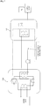
- the hydrogen refueling system 100 of the first embodiment is explained by referring figure 1 and 2 .
- the hydrogen refueling system 100 includes a liquid nitrogen (LN 2 ) tank 110 and Dispenser 120.
- LN 2 tank 110 stores the liquid nitrogen (LN 2 ).
- Dispenser 120 is explained below.
- Dispenser 120 supplies H 2 to a vehicle.
- Dispenser 120 includes the heat exchanger 121 that cools H 2 with LN 2 provided from the LN 2 tank 110.
- Dispenser 120 includes the dispenser hose and the refueling nozzle for refueling H 2 to a vehicle.
- the temperature control unit 151 measures the temperature (t1) of the heat exchanger metal mass.
- the temperature control unit 151 may measures the temperature at a wall of the heat exchanger 121, at a channel of the outlet line 132 within the heat exchanger 121.
- the temperature control unit 151 includes both function of a temperature measuring unit and a valve control unit.
- the temperature control unit 151 may measures the temperature of LN 2 at outlet of the heat exchanger 121 in the outlet line 132.
- the temperature measuring unit may measures the temperature (t1) of the heat exchanger 121.
- the temperature measuring unit may be provided at a wall of the heat exchanger 121, at a channel of the outlet line 132 within the heat exchanger 121 or within the heat exchanger metal mass.
- the inlet line 130 is a line for sending LN 2 to the heat exchanger 121 from LN 2 tank 110.
- the outlet line 132 is a line for collecting LN 2 from the heat exchanger 121.
- the inlet line 130 or the outlet line 132 is configured may be usual pipe or an insulated pipe.
- the injection valve 131 is provided at an inlet side of the heat exchanger 121 at the inlet line 130 but the injection valve 131 may be located at any point of the inlet line 130.
- the vehicle detection system 140 detects that a vehicle to be refueled with H 2 is entering the HRS(Hydrogen Refueling Station).
- the vehicle detection system 140 is for example of a camera with image treatment system, IR detector, pressure detector on the ground, magnetic loop in the ground or a combination of several detectors and/ or techniques.
- the controller 50 may be configured by combination between hardware and software program, firmware, dedicated circuit or combination of thereof.
- the controllerl 50 includes one or more function unit(it is so called function module).
- the controller 150 controls opening the injection valve 131 on the basis of a detection result of the vehicle detection system 140 and on the basis of specific control strategy. More specifically, the controller 150 is constituted by the following elements.
- the temperature control unit 151 can adjust the opening ratio of the injection valve 131 depending on measured temperature (t1) so that the temperature (151) measured by the temperature control unit 151 is maintained within a predetermined temperature range (or close to the target temperature). By adjusting the opening ratio of the injection valve 131, the heat exchanger 121 is cooled quickly down to a predetermined target temperature and the temperature of H 2 during refueling can be kept within the desired temperature range after reaching the predetermined temperature range.
- the temperature comparison unit 152 determines whether the temperature (t1) measured by the temperature control unit 151 is maintained within the predetermined temperature range (or close enough to the target temperature).
- the output unit 153 outputs a ready- to-fill signal when the temperature comparison unit 152 determined that the measured temperature (t1) is within the predetermined temperature range (or close enough to the target temperature).
- the predetermined temperature range for the heat exchanger temperature (t1) may be for example -45°C to -35°C, with a target temperature lying in between.
- the desired temperature range of H 2 at dispenser outlet during refueling may be for example -40 °C to -33°C.
- the output unit 153 sends releasing ready- to- fill signal to a refueling control unit 154.
- the refueling control unit 154 controls H 2 refueling flow to vehicles by Dispenser 120. During H 2 refueling, the refueling control unit 154 controls the opening ratio of a H 2 control valve 123 on a dispenser H 2 line 125 that connects one high pressure H 2 source 126, so as to feed H 2 into the heat exchanger 121 from H 2 source 126.
- the refueling control unit 154 has interlocking logic and/or sequence logic with transition conditions.
- H 2 control valve 123 cannot be opened or is closed by the function of the interlocking logic and/or sequence logic.
- H 2 can be refueled by releasing relevant interlocks and/or affecting H 2 refueling sequence transition conditions.
- the refueling control unit 154 releases the corresponding interlock condition on H 2 control valve 123 and/or affect the status of transition conditions of H 2 refueling sequence. Subsequently, when all other conditions and/or interlocks prohibiting to start H 2 refueling to vehicle are released, and upon manual command by operator or customer, the refueling control unit starts refueling and opens the H 2 control valve 123.
- the refueling control unit 154 displays information about the status of heat exchanger temperature condition to start H 2 refueling to vehicle. When all conditions and/or interlocks prohibiting to start H 2 refueling to vehicle are released, the refueling control unit 154 send signal to display an information that H 2 refueling to vehicle can be started and/or to inform by audio device.
- the refueling control unit 154 sends a signal of end of refueling.
- the signal of end of refueling is for example a signal for indicating (informing) that filling termination conditions have been reached and that H 2 control valve 123 has been closed.
- the vehicle queuing calculation unit 155 calculates a signal indicating that no vehicle is waiting for refueling by using the detection signal(s) from the vehicle detection system 140.
- the vehicle queuing calculation unit 155 may include a possibility of manual input by the operator that no vehicle is waiting for refueling.
- the vehicle queuing calculation unit 155 may use the end of refueling signal to calculate the signal indicating that no vehicle is waiting for refueling.
- the temperature control unit 151 may control to close the injection valve 131 only after receiving signal from the vehicle queuing calculation unit 155 that no vehicle is waiting for refueling.
- the injection valve 131 is closed, the system 100 come back to ambient temperature(step S11).
- the controller 150 may control opening of the injection valve 131 in such a way that during part of the idle time of the system 100, the heat exchanger 121 that cools H 2 with LN 2 provided from the tank 110 heats up more than 7°C above its nominal temperature during FCV refueling , and that it is cooled down upon arrival of a vehicle to be refilled.
- the vehicle detection system 140 detects that a vehicle to be refueled with H 2 is entering the HRS (transition T11).
- the controller 150 controls opening of the injection valve 131 and cold and/or liquid nitrogen is fed into the heat exchanger 121 through the inlet line 130 from the tank 110 (step S12).
- the temperature within the heat exchanger 121 cools down rapidly.
- LN 2 which is possibly mixture in liquid and/ or gaseous phase is sent to the vent or the recycling process through the outlet line 132 from the heat exchanger 121.
- the temperature control unit 151 controls the injection valve 131 on a fixed high opening ratio upon detection of FCV entering the HRS, thus providing high cooling power.
- the temperature of heat exchanger 121 is measured by the temperature control unit 151.
- the temperature comparison unit 152 determines whether the temperature (t1) measured by the temperature control unit 151 is maintained within the predetermined temperature range or close enough to the target temperature.
- the vehicle to be refueled is positioned in front of the dispenser. Then, operator or customer connects the FCV receptacle to the dispenser using dispenser hose and nozzle.
- the output unit 153 outputs a ready- to-fill signal when the temperature comparison unit 152 determined that the measured temperature (t1) is within the predetermined temperature range or close enough to the target temperature.
- the refueling control unit 154 releases the corresponding interlock condition on H 2 control valve 123 and/or affect the status of transition conditions of H 2 refueling sequence.
- the temperature control unit 151 After receiving the ready-to-fill signal from the output unit 153, the temperature control unit 151 changes strategy to adjust opening ratio of the injection valve 131, depending on the heat exchanger measured temperature (t1), so that it is within the predetermined temperature range or close enough to the target temperature.
- step S13 transition T12
- HRS is in ready- to- fill status and cold/liquid nitrogen continues to circulate, in order to maintain the heat exchanger within a predetermined temperature range or close to the target temperature (step S13).
- the temperature control unit 151 continues to use the same strategy to maintain the heat exchanger temperature (t1) within a predetermined temperature range.
- the refueling control unit 154 displays information about the status of heat exchanger temperature condition to start H 2 refueling to vehicle.
- the refueling control unit 154 send signal to display an information that H 2 refueling to vehicle can be started and/or to inform by audio device.
- the refueling control unit 154 controls H 2 control valve 123, in order to transfer hydrogen from the hydrogen high pressure source 126 to the tank of FCV; and cold/liquid nitrogen continues to circulate, in order to maintain the heat exchanger within a predetermined temperature range or close to the target temperature (step S14).
- the temperature control unit 151 continues to use the same strategy to maintain the heat exchanger temperature (t1) within a predetermined temperature range.
- the refueling control unit 154 sends a signal of end of refueling indicating (informing) that filling termination conditions have been reached and that H 2 control valve 123 has been closed (transition T14).
- step S11 If the vehicle queuing calculation unit 155 sends signal that no other vehicle is waiting for refueling, the system goes to step S11, which is already described above.
- step S15 If the vehicle queuing calculation unit 155 sends signal that another vehicle is waiting for refueling, the system goes to step S15, which is described below.
- the next vehicle to be refueled is positioned in front of the dispenser. Then, operator or customer connects the FCV receptacle to the dispenser using dispenser hose and nozzle (step S15).
- the temperature control unit 151 continues to use the same strategy to maintain the heat exchanger temperature (t1) within a predetermined temperature range.
- step S13 which is already described above (transition T12).
- the weight of compact stainless steel diffusion bonded heat exchangers used in H 2 dispensers can be around 150 kg. Around 5000 kJ are necessary to cool down the mass of the heat exchanger from 30°C to -40°C.
Landscapes
- Engineering & Computer Science (AREA)
- Mechanical Engineering (AREA)
- General Engineering & Computer Science (AREA)
- Filling Or Discharging Of Gas Storage Vessels (AREA)
- Fuel Cell (AREA)
Description
- The present invention relates to a hydrogen refueling system, for example a hydrogen refueling station (HRS).
- According to current standards of refueling protocols, to achieve fast refueling of Fuel Cell Vehicles (FCV) tanks with 70 MPa nominal hydrogen refueling pressure, the hydrogen needs to be pre-cooled below -33°C, at dispenser outlet, in order to avoid overheating in FCV tank by adiabatic compression.
- Today, this is done by having one heat exchanger, typically compact diffusion bonded heat exchanger, installed in the
dispenser 520, and fed with a heat carrying fluid, typically brine (seeFigure 3 , prior art). The heat carrying fluid is circulated between thetraditional chiller 510 using refrigerant and thedispenser 520 by means of a pump. - In order to keep the HRS ready-to-fill coming vehicles, the heat exchanger is kept permanently at around -40°C. Due to frigorific losses on the system (heat carrying fluid loop, heat exchanger, chiller 510), the consumption of electricity is high, especially during summer. Considering that the FCV load of one HRS is typically very irregular, this is highly inefficient during periods of time when no FCV is coming. However, it is not possible to stop the chiller and let the system come back to ambient temperature, because cooling time of the complete system cannot be accepted as waiting time for a customer coming.
- Previously, nominal H2refueling pressure in FCV was limited to 35 MPa. In this situation, there is little overheating of FCV tank caused by adiabatic compression at the time of refueling, and H2 pre-cooling is not necessary. In order to increase FCV autonomy, nominal H2 refueling pressure has been increased to 70 MPa. In the new situation, and to achieve fast FCV refueling according to current standards of refueling protocols, H2 pre-cooling is needed upstream FCV tank because otherwise, the overheating of FCV tank would exceed the capability of the composite materials currently used to make FCV tanks (such as polyethylene). In pre-cooling, for the lowest dispenser fuel delivery temperature category (corresponding to fastest refueling), it is needed to cool H2 so that the temperature at the outlet of the dispenser is between -33°C and -40°C.
- The target of 70 MPa FCV refueling is to reach nominal H2 density in FCV tank corresponding to 70 MPa at 15°C (i.e. 40.2 g/l), within about 3 minutes for 5 kg H2 fueling quantity. Without pre-cooling, the nominal filling of FCV tank could not be achieved fast enough.
- In the prior art system of
figure 3 , because all the elements within the dotted line must be at a low temperature, the time needed to cool down the system upon start-up is long. Also, due to frigorific losses of the system, even though no cold is needed for H2 refueling, permanent power consumption is observed during opening times of HRS. It causes high electricity costs even if during long periods of time, no FCV refueling is performed. - This is not efficient and savings could be achieved if it was possible to stop the chiller during idle time of the HRS. In the current situation, this is not possible because the time needed to cool down all the elements within the dotted line of
figure 3 could not be accepted as waiting time for the customer. As a matter of fact, cooling down the metal mass of the H2 pre-cooling heat exchanger is a necessary preliminary condition to start refueling. - Also, other prior art described
WO 2016/067780 is known, but cannot solve the above problems. The documentUS 2009/0229701 A1 discloses a further refueling system. - Objects of the present invention are to provide a hydrogen refueling system capable to cool down the H2pre-cooling heat exchanger fast enough when a FCV enters the HRS, so that there is no or very minimal waiting time for the customer before starting refueling. In the following, the expression "first invention" represents a refueling system and the expression "second invention" represents the corresponding method.
- As first invention, a hydrogen refueling system including:
- a cryogenic fluid tank that stores a cryogenic fluid;
- a dispenser that supplies H2 to a vehicle, including a heat exchanger that cools H2 with the cryogenic fluid provided from the cryogenic fluid tank;
- an inlet line that sends the cryogenic fluid to the heat exchanger from the cryogenic fluid tank;
- an outlet line that collects the cryogenic fluid from the heat exchanger;
- an injection valve that is provided at the inlet line.
- In first invention, the hydrogen refueling system is configured so that during part of the idle time of the system, the heat exchanger that cools H2 with the cold and/or cryogenic fluid provided from the cryogenic fluid tank heats up more than 7°C above its nominal temperature during FCV refueling, and that it is cooled down upon arrival of a vehicle to be refilled.
- In first invention, the system further may include:
- a vehicle detection system that detects that a vehicle to be refueled with H2 is entering the HRS; and
- a controller that controls the opening of the injection valve on a basis of a detection result of the vehicle detection system and on a basis of specific control strategy.
- In first invention, the specific control strategy may include one or more control types, such as temperature control, pressure control, predetermined fixed opening values.
- In first invention, the controller may control opening of the injection valve in such a way that during part of the idle time of the system, the heat exchanger that cools H2 with the cold and/or cryogenic fluid provided from the cryogenic fluid tank heats up more than 7°C above its nominal temperature during FCV refueling, and that it is cooled down upon arrival of a vehicle to be refilled.
- In first invention, to control opening of the injection valve may include opening and closing the injection valve.
- In first invention, the system further may include: a temperature measuring unit that measures the temperature of the heat exchanger;
a valve control unit that makes an adjustment of the opening ratio of the injection valve so that the temperature measured by the temperature measuring unit is maintained within a predetermined temperature range or close to the target temperature. - In first invention, the controller may include the valve control unit.
- In first invention, the system further may include:
- a temperature comparison unit that determines whether the temperature of the heat exchanger measured by the temperature measuring unit is within a predetermined temperature range or close enough to the target temperature; and
- an output unit that outputs a ready- to-fill signal when the temperature comparison unit determined that the measured temperature is within the predetermined temperature range or close enough to the target temperature.
- In first invention, the controller further may include a refueling control unit that controls H2 refueling flow to vehicles; wherein, receiving ready-to-fill signal from the output unit, is one condition used by the refueling control unit to permit H2 refueling flow to vehicles.
- According to first invention, without maintaining the heat exchanger at cold temperature during HRS idle time, cooling of the heat exchanger is started when a vehicle entering the HRS is detected. By opening the injection valve that is located on the inlet line, cold and/or cryogenic fluid from the cryogenic fluid tank is fed into the heat exchanger, in order to cool it down. With this method, the only pieces of equipment that need to be cooled down to reach the condition to start refueling are the heat exchanger and the line from the cryogenic fluid tank to the heat exchanger. This can be done fast enough to have no or minimal waiting time of the customer before starting refueling. Upon starting refueling, H2 is fed into the pre-cooled heat exchanger by opening H2 supply valve, heat exchanger cold temperature is maintained by circulation of cold and/or cryogenic fluid. H2 cooled to a predetermined temperature can be refueled to the vehicle.
- In first invention, the controller may adjust opening of the injection valve in order to achieve fast cooling of the heat exchanger and temperature regulation once the target temperature is reached.
- In first invention, the temperature measuring unit(or probe) may measure a temperature (t1) representative of the heat exchanger metal mass average temperature. The valve control unit can adjust of the opening ratio of the injection valve so that the temperature (t1) measured by the temperature measuring unit is maintained within a predetermined temperature range or close to the target temperature.
- By adjusting the opening ratio of the injection valve, the heat exchanger is cooled quickly down to a predetermined target temperature and the temperature of H2 during refueling can be kept within the desired temperature range after reaching the predetermined temperature range.
- Depending on operating conditions, the valve control unit may use different control strategies, such as temperature control units, pressure controlling unit, level controlling units or predetermined fixed opening values.
- Temperature controlling units may be for example using PID algorithm to adjust the injection valve opening ratio depending on measured temperature (e.g. t1).
- In the first invention, the valve control unit may be used to control the temperature (t1) of the heat exchanger metal mass or to control the temperature of cryogenic fluid at outlet of the heat exchanger in the outlet line.
- Pressure controlling units may be for example using PID algorithm to adjust the injection valve opening ratio depending on measured pressure.
- Level controlling units may be for example using PID algorithm to adjust the valve injection valve opening ratio depending on measured level (e.g. cryogenic fluid level in cryogenic fluid tank).
- For example, the valve control unit may use a first strategy to achieve fast cooling, upon detection of FCV entering the HRS and, after the measured temperature (t1) reaches the predetermined temperature range, may use a second strategy to maintain the heat exchanger temperature (t1) or the temperature(t2) of the cryogenic fluid at the outlet of the exchanger within a predetermined temperature range, then use a third strategy during H2 refueling to FCV and finally use a fourth strategy after the end of refueling.
- For example, in first invention, the injection valve control unit may use a fixed opening ratio upon detection of FCV entering the HRS, until the measured temperature (t1) reaches the predetermined temperature range and then may use temperature control unit to maintain measured temperature (t1) within the predetermined temperature range.
- For example, in first invention, the valve control unit may close the injection valve after receiving the signal of end of refueling.
- In first invention, the temperature measuring unit may be provided at a wall of the heat exchanger, at a channel of the inlet line or the outlet line within the heat exchanger or within the heat exchanger metal mass.
- Alternatively, the temperature measuring unit may be provided at outlet of the heat exchanger in the outlet line, because the cryogenic fluid temperature at the outlet of the heat exchanger is representative of the average temperature of the metal mass of the heat exchanger, once it has been cooled down.
- In first invention, the predetermined temperature range for the heat exchanger temperature (t1) or the temperature of cryogenic fluid at outlet of the heat exchanger may be for example -45°C to -35°C, with a target temperature lying in between.
- In first invention, the desired temperature range of H2 at dispenser outlet during refueling may be for example -40°C to -33°C.
- In first invention, during H2 refueling, the refueling control unit may control the opening ratio of a H2 control valve on dispenser H2 line that connects one high pressure H2 source to the FCV tank, through the heat exchanger, the dispenser hose and the refueling nozzle. The refueling control unit may have interlocking logic and/or sequence logic with transition conditions.
- In first invention, the output unit may send ready-to-fill signal to a refueling control unit. Upon receiving ready-to-fill signal from the output unit, the refueling control unit may permit opening of the H2 control valve by releasing corresponding interlock and/ or affecting the status of transition conditions of H2 refueling sequence.
- In first invention, the refueling control unit may display information about the status of heat exchanger temperature condition to start H2 refueling to vehicle. When all conditions and/or interlocks prohibiting to start H2refueling to vehicle are released, the refueling control unit may send signal to display an information that H2 refueling to vehicle can be started and/or to inform by audio device.
- In first invention, upon refueling termination detected, the refueling control unit may send end of refueling signal to the controller or to the valve control unit.
- In first invention, the controller may include a vehicle queuing calculation unit, that is using the signal(s) from vehicle detection system to calculate a signal indicating that no vehicle is waiting for refueling.
- In first invention, the vehicle queuing calculation unit may further include a possibility of manual input by the operator that no vehicle is waiting for refueling.
- In first invention, the vehicle queuing calculation unit may further use the end of refueling signal to calculate the signal indicating that no vehicle is waiting for refueling.
- In first invention, the controller or the valve control unit may further control to close the injection valve after receiving the signal of end of refueling.
- In first invention, the controller or the valve control unit may further control to close the injection valve only after receiving signal from the vehicle queuing calculation unit that no vehicle is waiting for refueling.
- In first invention, the vehicle detection system consists for example of a camera with image treatment system, IR detector, pressure detector on the ground, magnetic loop in the ground or a combination of several detectors and/or techniques.
- As second invention, a method for H2refueling to vehicles including:
- detecting that a vehicle to be refueled with H2 is entering a hydrogen refueling station;
- opening of an injection valve that is provided in an inlet line;
- feeding cold and/or cryogenic fluid to a heat exchanger from a cryogenic fluid tank;
- cooling down the heat exchanger by cold and/or cryogenic fluid; and
- refueling cold H2 cooled down by the heat exchanger to the vehicle while maintaining a temperature of the heat exchanger within a predetermined temperature range or close to the target temperature.
- In second invention, the method is operated in such a way that during part of the idle time, the heat exchanger that cools H2 with the cold and/or cryogenic fluid provided from the cryogenic fluid tank heats up more than 7°C above its nominal temperature during FCV refueling, and that it is cooled down upon arrival of a vehicle to be refilled.
- In second invention, the method further may include: measuring a temperature (t1) of the heat exchanger;
determining whether the measured temperature (t1) within a predetermined temperature range or close enough to the target temperature;
outputting a ready-to-fill signal when determining that the measured temperature (t1) is within the predetermined temperature range or close enough to the target temperature; and
releasing a corresponding interlock condition on H2 control valve and/or affect the status of transition conditions of H2 refueling sequence. - In first and second invention, "cryogenic fluid" may include for example liquid nitrogen, liquid carbon dioxide.
-
- [
fig.1]Fig. 1 illustrates an explanatory diagram showing a hydrogen refilling system according toEmbodiment 1. - [
fig.2]Fig. 2 illustrates an explanatory flowchart showing a hydrogen refilling system according toEmbodiment 1. - [
fig.3]Fig. 3 illustrates an explanatory diagram showing prior art of a hydrogen refilling system. - Several embodiments of the present invention will be explained below. The embodiments explained below are to explain one example of the present invention. The present invention is not limited to the following embodiments at all and includes various types of modifications carried out within a scope where the gist of the present invention is not changed. All of the configurations explained below are not necessarily essential configurations of the present invention.
- The
hydrogen refueling system 100 of the first embodiment is explained by referringfigure 1 and2 . Thehydrogen refueling system 100 includes a liquid nitrogen (LN2)tank 110 andDispenser 120. LN2 tank 110 stores the liquid nitrogen (LN2). - First,
Dispenser 120 is explained below. -
Dispenser 120 supplies H2 to a vehicle.Dispenser 120 includes theheat exchanger 121 that cools H2 with LN2 provided from the LN2 tank 110.Dispenser 120 includes the dispenser hose and the refueling nozzle for refueling H2 to a vehicle. - In this embodiment, the
temperature control unit 151 measures the temperature (t1) of the heat exchanger metal mass. Thetemperature control unit 151 may measures the temperature at a wall of theheat exchanger 121, at a channel of theoutlet line 132 within theheat exchanger 121. In this embodiment, thetemperature control unit 151 includes both function of a temperature measuring unit and a valve control unit. - In other embodiment, the
temperature control unit 151 may measures the temperature of LN2 at outlet of theheat exchanger 121 in theoutlet line 132. - In other embodiment, instead of the
temperature control unit 151, the temperature measuring unit may measures the temperature (t1) of theheat exchanger 121. The temperature measuring unit may be provided at a wall of theheat exchanger 121, at a channel of theoutlet line 132 within theheat exchanger 121 or within the heat exchanger metal mass. - The
inlet line 130 is a line for sending LN2 to theheat exchanger 121 from LN2 tank 110. Theoutlet line 132 is a line for collecting LN2 from theheat exchanger 121. Theinlet line 130 or theoutlet line 132 is configured may be usual pipe or an insulated pipe. - The
injection valve 131 is provided at an inlet side of theheat exchanger 121 at theinlet line 130 but theinjection valve 131 may be located at any point of theinlet line 130. - The
vehicle detection system 140 detects that a vehicle to be refueled with H2 is entering the HRS(Hydrogen Refueling Station). Thevehicle detection system 140 is for example of a camera with image treatment system, IR detector, pressure detector on the ground, magnetic loop in the ground or a combination of several detectors and/ or techniques. - Next, the
controller 150 is explained below. The controller 50 may be configured by combination between hardware and software program, firmware, dedicated circuit or combination of thereof. the controllerl 50 includes one or more function unit(it is so called function module). - The
controller 150 controls opening theinjection valve 131 on the basis of a detection result of thevehicle detection system 140 and on the basis of specific control strategy. More specifically, thecontroller 150 is constituted by the following elements. - The
temperature control unit 151 can adjust the opening ratio of theinjection valve 131 depending on measured temperature (t1) so that the temperature (151) measured by thetemperature control unit 151 is maintained within a predetermined temperature range (or close to the target temperature). By adjusting the opening ratio of theinjection valve 131, theheat exchanger 121 is cooled quickly down to a predetermined target temperature and the temperature of H2 during refueling can be kept within the desired temperature range after reaching the predetermined temperature range. - The
temperature comparison unit 152 determines whether the temperature (t1) measured by thetemperature control unit 151 is maintained within the predetermined temperature range (or close enough to the target temperature). - The
output unit 153 outputs a ready- to-fill signal when thetemperature comparison unit 152 determined that the measured temperature (t1) is within the predetermined temperature range (or close enough to the target temperature). - In this embodiment, the predetermined temperature range for the heat exchanger temperature (t1) may be for example -45°C to -35°C, with a target temperature lying in between.
- The desired temperature range of H2 at dispenser outlet during refueling may be for example -40 °C to -33°C.
- The
output unit 153 sends releasing ready- to- fill signal to arefueling control unit 154. - The
refueling control unit 154 controls H2 refueling flow to vehicles byDispenser 120. During H2 refueling, therefueling control unit 154 controls the opening ratio of a H2 control valve 123 on a dispenser H2 line 125 that connects one high pressure H2 source 126, so as to feed H2 into theheat exchanger 121 from H2 source 126. - The
refueling control unit 154 has interlocking logic and/or sequence logic with transition conditions. Typically, H2 control valve 123 cannot be opened or is closed by the function of the interlocking logic and/or sequence logic. H2 can be refueled by releasing relevant interlocks and/or affecting H2refueling sequence transition conditions. - In this embodiment, after receiving the ready- to- fill signal from the
output unit 153, therefueling control unit 154 releases the corresponding interlock condition on H2 control valve 123 and/or affect the status of transition conditions of H2 refueling sequence. Subsequently, when all other conditions and/or interlocks prohibiting to start H2refueling to vehicle are released, and upon manual command by operator or customer, the refueling control unit starts refueling and opens the H2 control valve 123. - The
refueling control unit 154 displays information about the status of heat exchanger temperature condition to start H2 refueling to vehicle. When all conditions and/or interlocks prohibiting to start H2 refueling to vehicle are released, therefueling control unit 154 send signal to display an information that H2 refueling to vehicle can be started and/or to inform by audio device. - The
refueling control unit 154 sends a signal of end of refueling. The signal of end of refueling is for example a signal for indicating (informing) that filling termination conditions have been reached and that H2 control valve 123 has been closed. - In this embodiment, the vehicle queuing
calculation unit 155 calculates a signal indicating that no vehicle is waiting for refueling by using the detection signal(s) from thevehicle detection system 140. The vehicle queuingcalculation unit 155 may include a possibility of manual input by the operator that no vehicle is waiting for refueling. The vehicle queuingcalculation unit 155 may use the end of refueling signal to calculate the signal indicating that no vehicle is waiting for refueling. In this embodiment, thetemperature control unit 151 may control to close theinjection valve 131 only after receiving signal from the vehicle queuingcalculation unit 155 that no vehicle is waiting for refueling. - Next flowchart of
figure 2 is explained below. - In the HRS idle time, the
injection valve 131 is closed, thesystem 100 come back to ambient temperature(step S11). - As another embodiment instead that the
system 100 comes back to ambient temperature, thecontroller 150 may control opening of theinjection valve 131 in such a way that during part of the idle time of thesystem 100, theheat exchanger 121 that cools H2 with LN2 provided from thetank 110 heats up more than 7°C above its nominal temperature during FCV refueling , and that it is cooled down upon arrival of a vehicle to be refilled. - The
vehicle detection system 140 detects that a vehicle to be refueled with H2 is entering the HRS (transition T11). - The
controller 150 controls opening of theinjection valve 131 and cold and/or liquid nitrogen is fed into theheat exchanger 121 through theinlet line 130 from the tank 110 (step S12). The temperature within theheat exchanger 121 cools down rapidly. LN2 which is possibly mixture in liquid and/ or gaseous phase is sent to the vent or the recycling process through theoutlet line 132 from theheat exchanger 121. - The
temperature control unit 151 controls theinjection valve 131 on a fixed high opening ratio upon detection of FCV entering the HRS, thus providing high cooling power. - The temperature of
heat exchanger 121 is measured by thetemperature control unit 151. Thetemperature comparison unit 152 determines whether the temperature (t1) measured by thetemperature control unit 151 is maintained within the predetermined temperature range or close enough to the target temperature. - In the meantime the vehicle to be refueled is positioned in front of the dispenser. Then, operator or customer connects the FCV receptacle to the dispenser using dispenser hose and nozzle.
- The
output unit 153 outputs a ready- to-fill signal when thetemperature comparison unit 152 determined that the measured temperature (t1) is within the predetermined temperature range or close enough to the target temperature. After receiving the ready-to- fill signal from theoutput unit 153, therefueling control unit 154 releases the corresponding interlock condition on H2 control valve 123 and/or affect the status of transition conditions of H2refueling sequence. - After receiving the ready-to-fill signal from the
output unit 153, thetemperature control unit 151 changes strategy to adjust opening ratio of theinjection valve 131, depending on the heat exchanger measured temperature (t1), so that it is within the predetermined temperature range or close enough to the target temperature. - Subsequently, when other ready- to- fill conditions are fulfilled (e.g. detection that dispenser nozzle has been connected to FCV receptacle), the system is goes to step S13 (transition T12).
- HRS is in ready- to- fill status and cold/liquid nitrogen continues to circulate, in order to maintain the heat exchanger within a predetermined temperature range or close to the target temperature (step S13). The
temperature control unit 151 continues to use the same strategy to maintain the heat exchanger temperature (t1) within a predetermined temperature range. - The
refueling control unit 154 displays information about the status of heat exchanger temperature condition to start H2 refueling to vehicle. Therefueling control unit 154 send signal to display an information that H2refueling to vehicle can be started and/or to inform by audio device. - The operator or customer gives start command of H2 refueling to the vehicle (transition T13).
- Following filling protocol, the
refueling control unit 154 controls H2 control valve 123, in order to transfer hydrogen from the hydrogenhigh pressure source 126 to the tank of FCV; and cold/liquid nitrogen continues to circulate, in order to maintain the heat exchanger within a predetermined temperature range or close to the target temperature (step S14). Thetemperature control unit 151 continues to use the same strategy to maintain the heat exchanger temperature (t1) within a predetermined temperature range. - The
refueling control unit 154 sends a signal of end of refueling indicating (informing) that filling termination conditions have been reached and that H2 control valve 123 has been closed (transition T14). - If the vehicle queuing
calculation unit 155 sends signal that no other vehicle is waiting for refueling, the system goes to step S11, which is already described above. - If the vehicle queuing
calculation unit 155 sends signal that another vehicle is waiting for refueling, the system goes to step S15, which is described below. - The next vehicle to be refueled is positioned in front of the dispenser. Then, operator or customer connects the FCV receptacle to the dispenser using dispenser hose and nozzle (step S15). The
temperature control unit 151 continues to use the same strategy to maintain the heat exchanger temperature (t1) within a predetermined temperature range. - Subsequently, when other ready- to- fill conditions are fulfilled (e.g. detection that dispenser nozzle has been connected to FCV receptacle), the system goes to step S13, which is already described above (transition T12).
- Currently, the weight of compact stainless steel diffusion bonded heat exchangers used in H2 dispensers can be around 150 kg. Around 5000 kJ are necessary to cool down the mass of the heat exchanger from 30°C to -40°C.
- This could be achieved within 3 minutes with around 30 kW frigorific power. Such power is achievable by injection of ∼500 1/h of liquid nitrogen.
Claims (7)
- A hydrogen refueling system comprising:a cryogenic fluid tank (110) that stores a cryogenic fluid;a dispenser (120) that supplies H2 to a vehicle, including a heat exchanger (121) that cools H2 with the cold and/orcryogenic fluid provided from the cryogenic fluid tank;an inlet line (130) that sends the cold and/or cryogenic fluid to the heat exchanger (121) from the cryogenic fluid tank;an outlet line (132) that collects the cryogenic fluid fed from the heat exchanger (121) ; andan injection valve that is provided in the inlet line (130);characterized in that the hydrogen refueling system is configured so that during part of the idle time of the system, the heat exchanger (121) that cools H2 with the cold and/or cryogenic fluid provided from the cryogenic fluid tank (110) heats up more than 7°C above its nominal temperature during FCV refueling, and that it is cooled down upon arrival of a vehicle to be refilled.
- A hydrogen refueling system according to claim 1,
the system further comprising:a vehicle detection system (140) that detects that a vehicle to be refueled with H2 is entering a hydrogen refueling station (HRS); anda controller (150) that controls the opening of the injection valve (131) on a basis of a detection result of the vehicle detection system (140) and on a basis of specific control strategy. - A hydrogen refueling system according to claim 1 or 2, the system further comprising:a temperature measuring unit that measures the temperature of the heat exchanger;a valve control unit (150) that makes an adjustment of the opening ratio of the injection valve (131) so that the temperature measured by the temperature measuring unit is maintained within a predetermined temperature range or close to the target temperature.
- A hydrogen refueling system according to claim 3, the system further comprising:a temperature comparison unit (152) that determines whether the temperature of the heat exchanger (121) measured by the temperature measuring unit is within a predetermined temperature range or close enough to the target temperature; andan output unit that outputs a ready- to-fill signal when the temperature comparison unit determined that the measured temperature is within the predetermined temperature range or close enough to the target temperature.
- A hydrogen refueling system according to claim 4, wherein the controller further comprises a refueling control unit (154) that controls H2 refueling flow to vehicles ; wherein, receiving ready-to-fill signal from the output unit, is one condition used by the refueling control unit to permit H2 refueling flow to vehicles.
- A method for H2 refueling to vehicles comprising:detecting that a vehicle to be refueled with H2 is entering a hydrogen refueling station;opening of an injection valve (131) that is provided in an inlet line (130) ;feeding cold and/or cryogenic fluid to a heat exchanger from a cryogenic fluid tank;cooling down the heat exchanger (121) by cold and/or cryogenic fluid; andrefueling cold H2 cooled down by the heat exchanger to the vehicle while maintaining a temperature of the heat exchanger within a predetermined temperature range or close to the target temperature;wherein the method is operated in such a way that during part of the idle time, the heat exchanger (121) that cools H2 with the cold and/or cryogenic fluid provided from the cryogenic fluid tank heats up more than 7°C above its nominal temperature during FCV refueling, and that it is cooled down upon arrival of a vehicle to be refilled.
- A method according to claim 6, further comprising:measuring a temperature (t1) of the heat exchanger;determining whether the measured temperature (t1) is within a predetermined temperature range or close enough to the target temperature;outputting a ready-to-fill signal when determining that the measured temperature (t1) is within the predetermined temperature range or close enough to the target temperature;and releasing a corresponding interlock condition on H2 control valve and/or affecting the status of transition conditions of H2 refueling sequence.
Applications Claiming Priority (1)
| Application Number | Priority Date | Filing Date | Title |
|---|---|---|---|
| PCT/JP2016/005074 WO2018104983A1 (en) | 2016-12-06 | 2016-12-06 | Hydrogen refueling system |
Publications (2)
| Publication Number | Publication Date |
|---|---|
| EP3551925A1 EP3551925A1 (en) | 2019-10-16 |
| EP3551925B1 true EP3551925B1 (en) | 2020-10-21 |
Family
ID=57708694
Family Applications (1)
| Application Number | Title | Priority Date | Filing Date |
|---|---|---|---|
| EP16820368.5A Active EP3551925B1 (en) | 2016-12-06 | 2016-12-06 | Hydrogen refueling system |
Country Status (7)
| Country | Link |
|---|---|
| US (1) | US11079067B2 (en) |
| EP (1) | EP3551925B1 (en) |
| JP (1) | JP6788115B2 (en) |
| CN (1) | CN109964074B (en) |
| DK (1) | DK3551925T3 (en) |
| ES (1) | ES2830781T3 (en) |
| WO (1) | WO2018104983A1 (en) |
Families Citing this family (12)
| Publication number | Priority date | Publication date | Assignee | Title |
|---|---|---|---|---|
| DE102016217673B4 (en) | 2016-09-15 | 2020-06-04 | Te Connectivity Germany Gmbh | Electrical contact for a connector, with rotatable rolling contact bodies and electrical plug connection with such a contact |
| DK3604892T3 (en) | 2018-08-01 | 2023-08-28 | Air Liquide | DEVICE AND PROCEDURE FOR FILLING CONTAINERS WITH PRESSURED GAS |
| EP3604978A1 (en) | 2018-08-01 | 2020-02-05 | L'air Liquide, Societe Anonyme Pour L'etude Et L'exploitation Des Procedes Georges Claude | Device and process for refuelling containers with pressurized gas |
| DK3604890T3 (en) | 2018-08-01 | 2023-08-21 | Air Liquide | DEVICE AND PROCEDURE FOR FILLING CONTAINERS WITH PRESSURED GAS |
| US11506339B2 (en) * | 2018-08-01 | 2022-11-22 | L'air Liquide, Societe Anonyme Pour L'etude Et L'exploitation Des Procedes Georges Claude | Device and process for refueling containers with pressurized gas |
| CN110792923A (en) | 2018-08-01 | 2020-02-14 | 乔治洛德方法研究和开发液化空气有限公司 | Device and method for filling a container with a pressurized gas |
| US11499765B2 (en) | 2018-08-01 | 2022-11-15 | L'air Liquide, Societe Anonyme Pour L'etude Et L'exploitation Des Procedes Georges Claude | Device and process for refueling containers with pressurized gas |
| KR102290401B1 (en) * | 2020-01-10 | 2021-08-18 | 유니셈 주식회사 | Extremely low temperature chiller apparatus for semiconductor |
| CN114076261B (en) * | 2020-08-17 | 2023-12-19 | 安瑞科(廊坊)能源装备集成有限公司 | Natural gas filling system and filling method |
| PL4009010T3 (en) * | 2020-12-02 | 2024-03-25 | Its Ingenieurbüro T. Steuer | Measuring system for determining a quantity of hydrogen emitted and method thereof |
| CN115307057B (en) * | 2022-07-18 | 2024-04-02 | 东风汽车集团股份有限公司 | Hydrogen replacement and recovery system and replacement and recovery method |
| EP4491935A1 (en) * | 2023-07-12 | 2025-01-15 | Cryostar SAS | Method for operating a fuel dispensing system and fuel dispensing system |
Family Cites Families (12)
| Publication number | Priority date | Publication date | Assignee | Title |
|---|---|---|---|---|
| US6786245B1 (en) * | 2003-02-21 | 2004-09-07 | Air Products And Chemicals, Inc. | Self-contained mobile fueling station |
| US20050284154A1 (en) * | 2004-06-25 | 2005-12-29 | Peter Andrew M | System and method for storing hydrogen at cryogenic temperature |
| DE102005039202A1 (en) * | 2005-08-18 | 2007-02-22 | Linde Ag | Mobile, self-sufficient and immission-free hydrogen filling station |
| US7602143B2 (en) | 2005-11-04 | 2009-10-13 | Peter David Capizzo | System for replenishing energy sources onboard different types of automotive vehicles |
| JP4913427B2 (en) * | 2006-03-10 | 2012-04-11 | 大陽日酸株式会社 | Method and apparatus for filling hydrogen gas |
| DE102007011742A1 (en) * | 2007-03-10 | 2008-09-11 | Bayerische Motoren Werke Aktiengesellschaft | Process to refuel pressurised automotive fuel tank with liquid hydrogen |
| FR2928716B1 (en) * | 2008-03-11 | 2012-12-28 | Air Liquide | DEVICE AND METHOD FOR FILLING A PRESSURIZED GAS IN A RESERVOIR |
| JP5839546B2 (en) * | 2011-06-30 | 2016-01-06 | 株式会社神戸製鋼所 | Hydrogen station |
| US9494281B2 (en) * | 2011-11-17 | 2016-11-15 | Air Products And Chemicals, Inc. | Compressor assemblies and methods to minimize venting of a process gas during startup operations |
| FR3008165B1 (en) * | 2013-07-05 | 2017-10-27 | Air Liquide | METHOD AND STATION FOR FILLING A GAS TANK |
| FR3008166B1 (en) * | 2013-07-05 | 2015-06-26 | Air Liquide | STATION AND METHOD FOR FILLING GAS RESERVOIRS |
| WO2016067780A1 (en) * | 2014-10-31 | 2016-05-06 | 株式会社神戸製鋼所 | Hydrogen station |
-
2016
- 2016-12-06 WO PCT/JP2016/005074 patent/WO2018104983A1/en not_active Ceased
- 2016-12-06 DK DK16820368.5T patent/DK3551925T3/en active
- 2016-12-06 EP EP16820368.5A patent/EP3551925B1/en active Active
- 2016-12-06 CN CN201680090954.3A patent/CN109964074B/en active Active
- 2016-12-06 JP JP2019527934A patent/JP6788115B2/en not_active Expired - Fee Related
- 2016-12-06 US US16/466,162 patent/US11079067B2/en active Active
- 2016-12-06 ES ES16820368T patent/ES2830781T3/en active Active
Non-Patent Citations (1)
| Title |
|---|
| None * |
Also Published As
| Publication number | Publication date |
|---|---|
| US20200072417A1 (en) | 2020-03-05 |
| EP3551925A1 (en) | 2019-10-16 |
| CN109964074A (en) | 2019-07-02 |
| JP2019535981A (en) | 2019-12-12 |
| WO2018104983A1 (en) | 2018-06-14 |
| US11079067B2 (en) | 2021-08-03 |
| ES2830781T3 (en) | 2021-06-04 |
| CN109964074B (en) | 2021-10-26 |
| DK3551925T3 (en) | 2020-11-16 |
| JP6788115B2 (en) | 2020-11-18 |
Similar Documents
| Publication | Publication Date | Title |
|---|---|---|
| EP3551925B1 (en) | Hydrogen refueling system | |
| EP3551926B1 (en) | Hydrogen refueling system | |
| EP3784952B1 (en) | Cryogenic fluid dispensing system having a chilling reservoir | |
| US11287087B2 (en) | Device and process for refueling containers with pressurized gas | |
| US10920933B2 (en) | Device and process for refueling containers with pressurized gas | |
| JP7726888B2 (en) | Station and method for filling tanks of hydrogen-fueled vehicles | |
| US20230204159A1 (en) | Hydrogen refueling system and method of hydrogen refueling | |
| JP2003301999A (en) | System and method for dispensing pressurized gas | |
| US20140216601A1 (en) | Method and Device for Refilling a Storage Tank | |
| US20200224824A1 (en) | Device and process for filling a mobile refrigerant tank with a cryogenic refrigerant | |
| KR20250069544A (en) | Method and system for filling a tank of a hydrogen fuel vehicle | |
| US20190003648A1 (en) | Method for Cooling a First Cryogenic Pressure Vessel | |
| EP3196534A1 (en) | Method, fueling system and subcooling and condensing unit for filling tanks with a fuel such as lng | |
| US20220373137A1 (en) | Precooling system utilizing cryogenic liquid fuels for fueling pressurized vehicle gaseous onboard storage tank system with controlled dispensing temperatures | |
| KR20200104441A (en) | Charging device and method of hydrogen | |
| JP7227710B2 (en) | Apparatus and method for refilling a container with pressurized gas | |
| JP2020020412A (en) | Apparatus and method for refilling a container with pressurized gas | |
| US20250137592A1 (en) | Inline cooling system for hydrogen refueling stations | |
| US20250027616A1 (en) | System for precooling a hydrogen fuel dispenser | |
| JP7352336B2 (en) | Apparatus and method for replenishing containers with pressurized gas | |
| JP2020020415A (en) | Apparatus and method for refilling a container with pressurized gas | |
| JP2020020414A (en) | Apparatus and method for refilling a container with pressurized gas | |
| KR20240156559A (en) | Apparatus and method for dispensing a cryogenic fluid |
Legal Events
| Date | Code | Title | Description |
|---|---|---|---|
| STAA | Information on the status of an ep patent application or granted ep patent |
Free format text: STATUS: UNKNOWN |
|
| STAA | Information on the status of an ep patent application or granted ep patent |
Free format text: STATUS: THE INTERNATIONAL PUBLICATION HAS BEEN MADE |
|
| PUAI | Public reference made under article 153(3) epc to a published international application that has entered the european phase |
Free format text: ORIGINAL CODE: 0009012 |
|
| STAA | Information on the status of an ep patent application or granted ep patent |
Free format text: STATUS: REQUEST FOR EXAMINATION WAS MADE |
|
| 17P | Request for examination filed |
Effective date: 20190708 |
|
| AK | Designated contracting states |
Kind code of ref document: A1 Designated state(s): AL AT BE BG CH CY CZ DE DK EE ES FI FR GB GR HR HU IE IS IT LI LT LU LV MC MK MT NL NO PL PT RO RS SE SI SK SM TR |
|
| AX | Request for extension of the european patent |
Extension state: BA ME |
|
| DAV | Request for validation of the european patent (deleted) | ||
| DAX | Request for extension of the european patent (deleted) | ||
| GRAP | Despatch of communication of intention to grant a patent |
Free format text: ORIGINAL CODE: EPIDOSNIGR1 |
|
| STAA | Information on the status of an ep patent application or granted ep patent |
Free format text: STATUS: GRANT OF PATENT IS INTENDED |
|
| INTG | Intention to grant announced |
Effective date: 20200514 |
|
| GRAJ | Information related to disapproval of communication of intention to grant by the applicant or resumption of examination proceedings by the epo deleted |
Free format text: ORIGINAL CODE: EPIDOSDIGR1 |
|
| STAA | Information on the status of an ep patent application or granted ep patent |
Free format text: STATUS: REQUEST FOR EXAMINATION WAS MADE |
|
| GRAP | Despatch of communication of intention to grant a patent |
Free format text: ORIGINAL CODE: EPIDOSNIGR1 |
|
| STAA | Information on the status of an ep patent application or granted ep patent |
Free format text: STATUS: GRANT OF PATENT IS INTENDED |
|
| INTC | Intention to grant announced (deleted) | ||
| INTG | Intention to grant announced |
Effective date: 20200810 |
|
| GRAS | Grant fee paid |
Free format text: ORIGINAL CODE: EPIDOSNIGR3 |
|
| GRAA | (expected) grant |
Free format text: ORIGINAL CODE: 0009210 |
|
| STAA | Information on the status of an ep patent application or granted ep patent |
Free format text: STATUS: THE PATENT HAS BEEN GRANTED |
|
| AK | Designated contracting states |
Kind code of ref document: B1 Designated state(s): AL AT BE BG CH CY CZ DE DK EE ES FI FR GB GR HR HU IE IS IT LI LT LU LV MC MK MT NL NO PL PT RO RS SE SI SK SM TR |
|
| REG | Reference to a national code |
Ref country code: GB Ref legal event code: FG4D |
|
| REG | Reference to a national code |
Ref country code: CH Ref legal event code: EP |
|
| REG | Reference to a national code |
Ref country code: DE Ref legal event code: R096 Ref document number: 602016046381 Country of ref document: DE |
|
| REG | Reference to a national code |
Ref country code: IE Ref legal event code: FG4D |
|
| REG | Reference to a national code |
Ref country code: AT Ref legal event code: REF Ref document number: 1326182 Country of ref document: AT Kind code of ref document: T Effective date: 20201115 |
|
| REG | Reference to a national code |
Ref country code: DK Ref legal event code: T3 Effective date: 20201113 |
|
| REG | Reference to a national code |
Ref country code: SE Ref legal event code: TRGR |
|
| REG | Reference to a national code |
Ref country code: NL Ref legal event code: FP |
|
| REG | Reference to a national code |
Ref country code: NO Ref legal event code: T2 Effective date: 20201021 |
|
| REG | Reference to a national code |
Ref country code: AT Ref legal event code: MK05 Ref document number: 1326182 Country of ref document: AT Kind code of ref document: T Effective date: 20201021 |
|
| PG25 | Lapsed in a contracting state [announced via postgrant information from national office to epo] |
Ref country code: RS Free format text: LAPSE BECAUSE OF FAILURE TO SUBMIT A TRANSLATION OF THE DESCRIPTION OR TO PAY THE FEE WITHIN THE PRESCRIBED TIME-LIMIT Effective date: 20201021 Ref country code: PT Free format text: LAPSE BECAUSE OF FAILURE TO SUBMIT A TRANSLATION OF THE DESCRIPTION OR TO PAY THE FEE WITHIN THE PRESCRIBED TIME-LIMIT Effective date: 20210222 Ref country code: GR Free format text: LAPSE BECAUSE OF FAILURE TO SUBMIT A TRANSLATION OF THE DESCRIPTION OR TO PAY THE FEE WITHIN THE PRESCRIBED TIME-LIMIT Effective date: 20210122 Ref country code: FI Free format text: LAPSE BECAUSE OF FAILURE TO SUBMIT A TRANSLATION OF THE DESCRIPTION OR TO PAY THE FEE WITHIN THE PRESCRIBED TIME-LIMIT Effective date: 20201021 |
|
| REG | Reference to a national code |
Ref country code: LT Ref legal event code: MG4D |
|
| PG25 | Lapsed in a contracting state [announced via postgrant information from national office to epo] |
Ref country code: AT Free format text: LAPSE BECAUSE OF FAILURE TO SUBMIT A TRANSLATION OF THE DESCRIPTION OR TO PAY THE FEE WITHIN THE PRESCRIBED TIME-LIMIT Effective date: 20201021 Ref country code: PL Free format text: LAPSE BECAUSE OF FAILURE TO SUBMIT A TRANSLATION OF THE DESCRIPTION OR TO PAY THE FEE WITHIN THE PRESCRIBED TIME-LIMIT Effective date: 20201021 Ref country code: IS Free format text: LAPSE BECAUSE OF FAILURE TO SUBMIT A TRANSLATION OF THE DESCRIPTION OR TO PAY THE FEE WITHIN THE PRESCRIBED TIME-LIMIT Effective date: 20210221 Ref country code: LV Free format text: LAPSE BECAUSE OF FAILURE TO SUBMIT A TRANSLATION OF THE DESCRIPTION OR TO PAY THE FEE WITHIN THE PRESCRIBED TIME-LIMIT Effective date: 20201021 Ref country code: BG Free format text: LAPSE BECAUSE OF FAILURE TO SUBMIT A TRANSLATION OF THE DESCRIPTION OR TO PAY THE FEE WITHIN THE PRESCRIBED TIME-LIMIT Effective date: 20210121 |
|
| REG | Reference to a national code |
Ref country code: ES Ref legal event code: FG2A Ref document number: 2830781 Country of ref document: ES Kind code of ref document: T3 Effective date: 20210604 |
|
| PG25 | Lapsed in a contracting state [announced via postgrant information from national office to epo] |
Ref country code: HR Free format text: LAPSE BECAUSE OF FAILURE TO SUBMIT A TRANSLATION OF THE DESCRIPTION OR TO PAY THE FEE WITHIN THE PRESCRIBED TIME-LIMIT Effective date: 20201021 |
|
| REG | Reference to a national code |
Ref country code: DE Ref legal event code: R097 Ref document number: 602016046381 Country of ref document: DE |
|
| PG25 | Lapsed in a contracting state [announced via postgrant information from national office to epo] |
Ref country code: SK Free format text: LAPSE BECAUSE OF FAILURE TO SUBMIT A TRANSLATION OF THE DESCRIPTION OR TO PAY THE FEE WITHIN THE PRESCRIBED TIME-LIMIT Effective date: 20201021 Ref country code: RO Free format text: LAPSE BECAUSE OF FAILURE TO SUBMIT A TRANSLATION OF THE DESCRIPTION OR TO PAY THE FEE WITHIN THE PRESCRIBED TIME-LIMIT Effective date: 20201021 Ref country code: LT Free format text: LAPSE BECAUSE OF FAILURE TO SUBMIT A TRANSLATION OF THE DESCRIPTION OR TO PAY THE FEE WITHIN THE PRESCRIBED TIME-LIMIT Effective date: 20201021 Ref country code: SM Free format text: LAPSE BECAUSE OF FAILURE TO SUBMIT A TRANSLATION OF THE DESCRIPTION OR TO PAY THE FEE WITHIN THE PRESCRIBED TIME-LIMIT Effective date: 20201021 Ref country code: CZ Free format text: LAPSE BECAUSE OF FAILURE TO SUBMIT A TRANSLATION OF THE DESCRIPTION OR TO PAY THE FEE WITHIN THE PRESCRIBED TIME-LIMIT Effective date: 20201021 Ref country code: EE Free format text: LAPSE BECAUSE OF FAILURE TO SUBMIT A TRANSLATION OF THE DESCRIPTION OR TO PAY THE FEE WITHIN THE PRESCRIBED TIME-LIMIT Effective date: 20201021 |
|
| REG | Reference to a national code |
Ref country code: CH Ref legal event code: PL |
|
| PLBE | No opposition filed within time limit |
Free format text: ORIGINAL CODE: 0009261 |
|
| STAA | Information on the status of an ep patent application or granted ep patent |
Free format text: STATUS: NO OPPOSITION FILED WITHIN TIME LIMIT |
|
| PG25 | Lapsed in a contracting state [announced via postgrant information from national office to epo] |
Ref country code: MC Free format text: LAPSE BECAUSE OF FAILURE TO SUBMIT A TRANSLATION OF THE DESCRIPTION OR TO PAY THE FEE WITHIN THE PRESCRIBED TIME-LIMIT Effective date: 20201021 |
|
| REG | Reference to a national code |
Ref country code: BE Ref legal event code: MM Effective date: 20201231 |
|
| 26N | No opposition filed |
Effective date: 20210722 |
|
| GBPC | Gb: european patent ceased through non-payment of renewal fee |
Effective date: 20210121 |
|
| PG25 | Lapsed in a contracting state [announced via postgrant information from national office to epo] |
Ref country code: LU Free format text: LAPSE BECAUSE OF NON-PAYMENT OF DUE FEES Effective date: 20201206 Ref country code: IE Free format text: LAPSE BECAUSE OF NON-PAYMENT OF DUE FEES Effective date: 20201206 Ref country code: AL Free format text: LAPSE BECAUSE OF FAILURE TO SUBMIT A TRANSLATION OF THE DESCRIPTION OR TO PAY THE FEE WITHIN THE PRESCRIBED TIME-LIMIT Effective date: 20201021 |
|
| PG25 | Lapsed in a contracting state [announced via postgrant information from national office to epo] |
Ref country code: GB Free format text: LAPSE BECAUSE OF NON-PAYMENT OF DUE FEES Effective date: 20210121 Ref country code: LI Free format text: LAPSE BECAUSE OF NON-PAYMENT OF DUE FEES Effective date: 20201231 Ref country code: SI Free format text: LAPSE BECAUSE OF FAILURE TO SUBMIT A TRANSLATION OF THE DESCRIPTION OR TO PAY THE FEE WITHIN THE PRESCRIBED TIME-LIMIT Effective date: 20201021 Ref country code: CH Free format text: LAPSE BECAUSE OF NON-PAYMENT OF DUE FEES Effective date: 20201231 |
|
| PG25 | Lapsed in a contracting state [announced via postgrant information from national office to epo] |
Ref country code: IS Free format text: LAPSE BECAUSE OF FAILURE TO SUBMIT A TRANSLATION OF THE DESCRIPTION OR TO PAY THE FEE WITHIN THE PRESCRIBED TIME-LIMIT Effective date: 20210221 Ref country code: TR Free format text: LAPSE BECAUSE OF FAILURE TO SUBMIT A TRANSLATION OF THE DESCRIPTION OR TO PAY THE FEE WITHIN THE PRESCRIBED TIME-LIMIT Effective date: 20201021 Ref country code: MT Free format text: LAPSE BECAUSE OF FAILURE TO SUBMIT A TRANSLATION OF THE DESCRIPTION OR TO PAY THE FEE WITHIN THE PRESCRIBED TIME-LIMIT Effective date: 20201021 Ref country code: CY Free format text: LAPSE BECAUSE OF FAILURE TO SUBMIT A TRANSLATION OF THE DESCRIPTION OR TO PAY THE FEE WITHIN THE PRESCRIBED TIME-LIMIT Effective date: 20201021 |
|
| PG25 | Lapsed in a contracting state [announced via postgrant information from national office to epo] |
Ref country code: MK Free format text: LAPSE BECAUSE OF FAILURE TO SUBMIT A TRANSLATION OF THE DESCRIPTION OR TO PAY THE FEE WITHIN THE PRESCRIBED TIME-LIMIT Effective date: 20201021 |
|
| PG25 | Lapsed in a contracting state [announced via postgrant information from national office to epo] |
Ref country code: BE Free format text: LAPSE BECAUSE OF NON-PAYMENT OF DUE FEES Effective date: 20201231 |
|
| PGFP | Annual fee paid to national office [announced via postgrant information from national office to epo] |
Ref country code: SE Payment date: 20231220 Year of fee payment: 8 Ref country code: NO Payment date: 20231222 Year of fee payment: 8 Ref country code: NL Payment date: 20231220 Year of fee payment: 8 Ref country code: IT Payment date: 20231221 Year of fee payment: 8 Ref country code: FR Payment date: 20231222 Year of fee payment: 8 Ref country code: DK Payment date: 20231227 Year of fee payment: 8 Ref country code: DE Payment date: 20231214 Year of fee payment: 8 |
|
| PGFP | Annual fee paid to national office [announced via postgrant information from national office to epo] |
Ref country code: ES Payment date: 20240130 Year of fee payment: 8 |
|
| REG | Reference to a national code |
Ref country code: DE Ref legal event code: R119 Ref document number: 602016046381 Country of ref document: DE |
|
| REG | Reference to a national code |
Ref country code: DK Ref legal event code: EBP Effective date: 20241231 |
|
| REG | Reference to a national code |
Ref country code: SE Ref legal event code: EUG |
|
| REG | Reference to a national code |
Ref country code: NL Ref legal event code: MM Effective date: 20250101 |
|
| PG25 | Lapsed in a contracting state [announced via postgrant information from national office to epo] |
Ref country code: NL Free format text: LAPSE BECAUSE OF NON-PAYMENT OF DUE FEES Effective date: 20250101 |
|
| PG25 | Lapsed in a contracting state [announced via postgrant information from national office to epo] |
Ref country code: DE Free format text: LAPSE BECAUSE OF NON-PAYMENT OF DUE FEES Effective date: 20250701 |
|
| PG25 | Lapsed in a contracting state [announced via postgrant information from national office to epo] |
Ref country code: IT Free format text: LAPSE BECAUSE OF NON-PAYMENT OF DUE FEES Effective date: 20241206 Ref country code: NO Free format text: LAPSE BECAUSE OF NON-PAYMENT OF DUE FEES Effective date: 20241231 |
|
| PG25 | Lapsed in a contracting state [announced via postgrant information from national office to epo] |
Ref country code: FR Free format text: LAPSE BECAUSE OF NON-PAYMENT OF DUE FEES Effective date: 20241231 |
|
| PG25 | Lapsed in a contracting state [announced via postgrant information from national office to epo] |
Ref country code: DK Free format text: LAPSE BECAUSE OF NON-PAYMENT OF DUE FEES Effective date: 20241231 |
|
| REG | Reference to a national code |
Ref country code: ES Ref legal event code: FD2A Effective date: 20260128 |
|
| PG25 | Lapsed in a contracting state [announced via postgrant information from national office to epo] |
Ref country code: ES Free format text: LAPSE BECAUSE OF NON-PAYMENT OF DUE FEES Effective date: 20241207 |