WO2016067780A1 - 水素ステーション - Google Patents
水素ステーション Download PDFInfo
- Publication number
- WO2016067780A1 WO2016067780A1 PCT/JP2015/076324 JP2015076324W WO2016067780A1 WO 2016067780 A1 WO2016067780 A1 WO 2016067780A1 JP 2015076324 W JP2015076324 W JP 2015076324W WO 2016067780 A1 WO2016067780 A1 WO 2016067780A1
- Authority
- WO
- WIPO (PCT)
- Prior art keywords
- housing
- compressor
- gas
- hydrogen station
- cooler
- Prior art date
Links
Images


Classifications
-
- F—MECHANICAL ENGINEERING; LIGHTING; HEATING; WEAPONS; BLASTING
- F17—STORING OR DISTRIBUTING GASES OR LIQUIDS
- F17C—VESSELS FOR CONTAINING OR STORING COMPRESSED, LIQUEFIED OR SOLIDIFIED GASES; FIXED-CAPACITY GAS-HOLDERS; FILLING VESSELS WITH, OR DISCHARGING FROM VESSELS, COMPRESSED, LIQUEFIED, OR SOLIDIFIED GASES
- F17C5/00—Methods or apparatus for filling containers with liquefied, solidified, or compressed gases under pressures
- F17C5/06—Methods or apparatus for filling containers with liquefied, solidified, or compressed gases under pressures for filling with compressed gases
-
- Y—GENERAL TAGGING OF NEW TECHNOLOGICAL DEVELOPMENTS; GENERAL TAGGING OF CROSS-SECTIONAL TECHNOLOGIES SPANNING OVER SEVERAL SECTIONS OF THE IPC; TECHNICAL SUBJECTS COVERED BY FORMER USPC CROSS-REFERENCE ART COLLECTIONS [XRACs] AND DIGESTS
- Y02—TECHNOLOGIES OR APPLICATIONS FOR MITIGATION OR ADAPTATION AGAINST CLIMATE CHANGE
- Y02E—REDUCTION OF GREENHOUSE GAS [GHG] EMISSIONS, RELATED TO ENERGY GENERATION, TRANSMISSION OR DISTRIBUTION
- Y02E60/00—Enabling technologies; Technologies with a potential or indirect contribution to GHG emissions mitigation
- Y02E60/30—Hydrogen technology
- Y02E60/32—Hydrogen storage
Definitions
- the present invention relates to a hydrogen station.
- Patent Document 1 discloses a mobile hydrogen station that includes a hydrogen production apparatus and a truck that can move in a state where the hydrogen production apparatus is loaded.
- the hydrogen station includes a compressor that compresses hydrogen gas, a pressure accumulator that stores hydrogen gas discharged from the compressor, a dispenser that fills the vehicle with hydrogen gas supplied from the pressure accumulator, and the like. Since the hydrogen station described in Patent Document 1 can be moved by truck, even if it is difficult to secure a site for installing the hydrogen station, the vehicle can be filled with hydrogen gas.
- An object of the present invention is to provide a hydrogen station capable of improving the degree of freedom of installation in a site.
- a hydrogen station includes a filling facility that fills a tank mounting device with a gas, and a gas supply system that supplies the gas to the filling facility, and the gas supply system compresses the gas.
- a compressor housing for housing the compressor, and a refrigerator for cooling the gas that has flowed into the filling facility or the gas that has just flowed in, and includes an evaporation section, an expansion section, and a compression section
- a cooler housing that houses the evaporating portion, the expansion portion, and the compression portion, and the compressor housing and the cooler housing are detachable from each other.
- FIG. 1 It is a figure which shows the hydrogen station which has the gas supply system which concerns on one Embodiment of this invention. It is a figure which shows a gas cooling part. It is a figure which shows a refrigerator. It is a side view of the hydrogen station shown in FIG. It is a top view which shows a hydrogen station. It is a top view which shows the other shape of a hydrogen station. It is a side view of the modification of the hydrogen station shown in FIG. It is a top view of the apparatus shown by the code
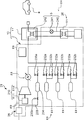
- FIG. 1 is a diagram showing an outline of the configuration of a hydrogen station 10 according to an embodiment of the present invention.
- the hydrogen station 10 includes a gas supply system 2 and a dispenser 11 that is a filling facility.
- the gas supply system 2 supplies hydrogen gas to the dispenser 11.
- the gas supply system 2 includes a gas flow path 20, a compressor unit 21, a pressure accumulator unit 23, a cooler unit 24, a receiving unit 28, and a control unit 29.
- a receiving unit 28, a compressor unit 21 and a pressure accumulator unit 23 are disposed on the gas flow path 20.
- Hydrogen gas flows in the gas flow path 20 toward the dispenser 11.
- the control unit 29 includes a control unit main body and a control unit frame that houses the control unit main body, as will be described later.
- the control unit main body controls the compressor unit 21, the accumulator unit 23, and the cooler unit 24.
- the compressor unit 21, the pressure accumulator unit 23, the cooler unit 24, the receiving unit 28, the dispenser 11, and the control unit 29 are collectively referred to as “main devices”.
- the term “unit” is used as a term meaning a functional block.
- the compressor unit 21 includes a reciprocating compressor 210, a later-described compressor housing that houses the compressor 210, and a gas cooling unit 22.
- the term “container” is used to mean a box-shaped structure that accommodates devices.
- the compressor 210 includes a drive unit 211 and a compression unit 212.
- the compression unit 212 includes a piston and a cylinder, and the piston is driven by the power of the drive unit 211 so that hydrogen gas is compressed in the cylinder.
- the number of compression units 212 is five.
- FIG. 2 is a diagram showing the configuration of the gas cooling unit 22.
- the gas cooling unit 22 includes a cooling water passage 220 filled with cooling water as a cooling fluid, a cooling water pump 221, a gas cooler 222 connected to the compression unit 212, and a heat exhausting unit 223.
- the gas cooler 222 is a microchannel heat exchanger.
- the gas flow path 20 shown in FIGS. 1 and 2 is connected to the gas cooler 222.
- the exhaust heat unit 223 includes a heat exchanger 223a and a fan 223b. In the cooling water flow path 220, a cooling water pump 221, a gas cooler 222, and a heat exchanger 223a of the exhaust heat unit 223 are arranged.
- the hydrogen gas in the gas flow path 20 is cooled by heat exchange between the hydrogen gas discharged from the discharge unit of the compression unit 212 and the cooling water in the gas cooler 222.
- the cooling water that has absorbed heat in the gas cooler 222 flows into the heat exchanger 223a of the exhaust heat unit 223 and is cooled by the air flow generated in the fan 223b.
- the cooling water cooled in the heat exchanger 223a is sent again to the gas cooler 222 by the cooling water pump 221.
- the pressure accumulator unit 23 includes a plurality of (three in this embodiment) pressure accumulators 231, valve members 232 a and 232 b, valve members 232 a and 232 b, and a pressure accumulator 231 described later.
- the accumulator 231 has a capsule shape.
- the accumulator 231 stores hydrogen gas discharged from the compressor unit 21. Further, hydrogen gas is sent from the pressure accumulator 231 toward the dispenser 11.
- the accumulators 231 are each designed to have the same design pressure (for example, 82 MPa).
- valve members 232a and 232b are provided on the inlet side and the outlet side of the pressure accumulator 231, and the control unit 29 controls the opening and closing of the valve members 232a and 232b, whereby hydrogen gas in the pressure accumulator 231 is obtained. Inflow and outflow are controlled.
- the gas supply system 2 further includes a return flow path 233, a reservoir tank 234, and valve members 235a and 235b.
- the return flow path 233 is a flow path for returning the hydrogen gas discharged from the compressor 210 to the upstream side of the compressor 210 in the gas flow path 20.
- the reservoir tank 234 stores hydrogen gas discharged from the compressor 210.
- the valve member 235a is provided in a part of the return channel 233 on the upstream side of the reservoir tank 234, and the valve member 235b is provided in a part of the return channel 233 on the downstream side of the reservoir tank 234. Yes. Storage of hydrogen gas in the reservoir tank 234, that is, opening / closing of the valve member 235a is controlled by the control unit 29.
- the control unit 29 closes the valve members 235a and 235b and opens the valve member 232a. And if the pressure of each pressure accumulator 231 becomes more than predetermined value (for example, 80 MPa), control part 29 will open valve member 235a. Then, a part of the hydrogen gas discharged from the compressor 210 is supplied to the reservoir tank 234, so that the flow rate of the hydrogen gas supplied to each pressure accumulator 231 decreases. Therefore, it is possible to suppress an overload from acting on the pressure accumulator 231 due to the excessive supply of hydrogen gas to the pressure accumulator 231 after the pressure of each pressure accumulator 231 becomes a predetermined value or more. Even if the valve member 235a is opened, the processing amount (hydrogen gas discharge amount) of the compressor 210 is sufficiently large, so that hydrogen gas does not flow into the reservoir tank 234 from each pressure accumulator 231.
- predetermined value for example 80 MPa
- the control unit 29 stops the compressor 210 and closes the valve member 235a.
- the pressure in the reservoir tank 234 is detected by a pressure sensor provided in a portion of the return channel 233 upstream of the reservoir tank 234.
- the control unit 29 compresses the hydrogen gas in the reservoir tank 234 before the pressure in the reservoir tank 234 reaches a specified value, for example, when the pressure in the reservoir tank 234 reaches a reference value lower than the specified value.
- the valve member 235a may be closed and the valve member 235b may be opened.
- the throughput of the compressor 210 is secured.
- the reservoir tank 234 is removed from the return flow path 233, and the reservoir tank 234 is transported to another facility (such as a hydrogen station) by a trailer or the like. Hydrogen gas in the tank 234 may be used.
- the downstream portion of the return flow path 233 from the reservoir tank 234 and the valve member 235b may be omitted.
- the cooler unit 24 includes a refrigerator 26, a brine circuit 5, and a cooler container described later.
- the brine circuit 5 includes a brine flow path 240, a brine pump 241, and a precool heat exchanger 242 that is a microchannel heat exchanger.
- the precool heat exchanger 242 is built in the dispenser 11.
- the brine circuit 5 may be provided with an unillustrated brine tank for storing brine.
- the brine channel 240 is filled with brine, and the brine pump 241, the precool heat exchanger 242, and the evaporator 31 of the refrigerator 26 are disposed.
- the hydrogen gas flowing into the dispenser 11 is cooled by heat exchange between the hydrogen gas and the brine in the precool heat exchanger 242.
- the brine that has absorbed heat in the precool heat exchanger 242 flows into the refrigerator 26 and is cooled.
- the brine cooled by the refrigerator 26 is sent again to the precool heat exchanger 242 by the brine pump 241.
- FIG. 3 is a diagram showing the configuration of the refrigerator 26.
- the refrigerator 26 includes a refrigerant flow path 30, an evaporation unit 31, a compression unit 32, a condensing unit 33, and an expansion unit 34.
- the refrigerant flow path 30 is filled with the refrigerant, and an evaporation unit 31, a compression unit 32, a condensation unit 33, and an expansion unit 34 are arranged.
- the evaporation part 31 is connected to the brine flow path 240 shown in FIGS. In the evaporation unit 31, the brine and the refrigerant exchange heat, thereby cooling the brine and evaporating the refrigerant.
- the compressor 32 shown in FIG. 3 compresses the refrigerant that has flowed out of the evaporator 31.
- the condensing unit 33 includes a heat exchanger 331 through which a refrigerant flows and a fan 332.
- the refrigerant flowing into the heat exchanger 331 from the compression unit 32 is radiated and condensed by the air flow generated by the fan 332.
- the expansion unit 34 expands the refrigerant that has flowed out of the condensation unit 33, and the expanded refrigerant flows into the evaporation unit 31.
- the refrigerator 26 can cool the hydrogen gas indirectly flowing into the dispenser 11 by cooling the brine by a so-called heat pump cycle.
- the receiving unit 28 shown in FIG. 1 includes a pressure reducing valve (not shown) and various instrumentation, and receives hydrogen gas supplied from the outside.
- the pressure reducing valve depressurizes the hydrogen gas so as to receive the hydrogen gas into the compression section 212 through the gas flow path 20, and is disposed on the suction side of the compression section 212 in the gas flow path 20.
- the dispenser 11 fills the vehicle 9 which is a tank mounting device with the hydrogen gas sent from the pressure accumulator 231.
- vehicle 9 is a fuel cell vehicle, for example.
- the hydrogen gas sent from the receiving unit 28 is compressed by the compressor 210 and stored in each pressure accumulator 231 while being cooled by the gas cooling unit 22.
- hydrogen gas is sent out from the first pressure accumulator 231 (for example, the upper pressure accumulator 231 in FIG. 1).
- symbol "231a" is attached
- the dispenser 11 indirectly measures the pressure in the vehicle 9 and determines that the pressure difference between the vehicle 9 and the pressure accumulator 231a is equal to or less than a predetermined value, the pressure is accumulated in the control unit 29 of the gas supply system 2. An instruction to stop the delivery of hydrogen gas from the vessel 231a is sent.
- the control unit 29 of the gas supply system 2 opens another pressure accumulator 231 (for example, the second pressure accumulator 231 from the top in FIG. 1), and hydrogen gas is sent to the dispenser 11.
- another pressure accumulator 231 for example, the second pressure accumulator 231 from the top in FIG. 1
- hydrogen gas is sent to the dispenser 11.
- the reference numeral “231b” is attached.
- the pressure difference between the dispenser 11 (or the pressure accumulator 231b) and the vehicle 9 is recovered, and the flow rate of hydrogen gas charged into the vehicle 9 is ensured.
- the control unit 29 of the gas supply system 2 receives the pressure from the pressure accumulator 231b. While stopping the delivery of hydrogen gas, another pressure accumulator (accumulator located on the lower side in FIG. 1) is opened to deliver hydrogen gas. Thereby, the pressure difference between the dispenser 11 and the vehicle 9 is ensured, and a sufficient amount of hydrogen gas is filled. When it is determined that the tank pressure in the vehicle 9 has reached the set value, the supply of hydrogen gas from the gas supply system 2 is stopped.
- one of the three pressure accumulators 231 is used in the low pressure region (for example, 0 MPa to 40 MPa) of the tank of the vehicle 9, and the other one is used in the medium pressure region (40 MPa to 60 MPa). The other one is used in the high pressure region (60 MPa to 70 MPa).
- the gas supply system 2 switches the pressure accumulator 231 in accordance with the three pressure regions of the vehicle 9, whereby the dispenser 11 can efficiently fill the hydrogen gas according to the filling protocol.
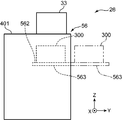
- FIG. 4 is a side view of the hydrogen station 10 and shows a state in which main devices are integrated.
- the hydrogen station 10 is shown with a common cover (to be described later) removed.
- FIG. 5 is a plan view of the hydrogen station 10 and corresponds to FIG. 4 and 5, only the main equipment of the hydrogen station 10 is shown, and the peripheral members are not shown. The same applies to FIG. 6 below.
- the compressor unit 21 includes a compressor housing 51 having a substantially rectangular parallelepiped shape that houses the compressor 210 and the gas cooler 222 (not shown in FIG. 5) shown in FIGS. 2 and 4. Have.
- the compressor housing 51 includes a compressor frame 511 that is a framework.
- the pressure accumulator unit 23 includes a pressure accumulator housing 53 having a substantially rectangular parallelepiped shape for housing the pressure accumulator 231 and the valve members 232a and 232b.
- the pressure accumulator housing 53 includes a pressure accumulator frame 531.
- the cooler unit 24 includes a substantially rectangular parallelepiped-shaped cooler housing 56 that houses the evaporation section 31, the compression section 32, the expansion section 34, and the brine pump 241 and the brine tank (not shown) illustrated in FIG. . That is, the cooler accommodating body 56 accommodates devices other than the precool heat exchanger 242 and the condensing unit 33 among the devices included in the cooler unit 24.
- the evaporation unit 31, the compression unit 32, the expansion unit 34, the brine pump 241, and the brine tank are shown as one rectangle with a reference numeral 300. The same applies to FIGS. 6 to 8 below.
- the cooler container 56 includes a cooler frame 561.
- the gas supply system 2 has one common cover 401 that covers the compressor frame 511, the pressure accumulator frame 531, and the entire cooler frame 561.
- a part covering the compressor frame 511, a part covering the pressure accumulator frame 531 and a part covering the cooler frame 561 are respectively a part of the compressor housing 51 and the pressure accumulating.
- a part of the container housing 53 and a part of the cooler housing 56 are configured.
- illustration of the upper part of the shared cover 401 is omitted for the sake of illustration, but actually the upper parts of the respective frames 511, 531, and 561 are also covered with the shared cover 401.
- the compressor frame 511 includes at least four column portions extending in the direction of gravity and a plurality of connecting portions that connect the column portions to each other.
- a substantially rectangular parallelepiped space is defined around the compressor 210 by the compressor frame 511.
- the pressure accumulator frame 531 includes at least four column portions extending in the direction of gravity and a plurality of connecting portions that connect the column portions, similarly to the compressor frame 511. .
- the accumulator frame 531 defines a substantially rectangular space around the accumulator 231.
- each of the three pressure accumulators 231 is placed in a posture that is parallel to the horizontal plane, and overlaps the gravitational direction that is the Z direction (in a state of being aligned along the gravitational direction). ing.
- the X direction of FIGS. 4 and 5, which is the direction in which the pressure accumulator 231 extends is referred to as the “longitudinal direction” of the hydrogen station 10.
- the exhaust heat unit 223 of the gas cooling unit 22 and the condensing unit 33 of the refrigerator 26 are arranged on the top of the pressure accumulator frame 531.
- the heat exhausting part 223 and the condensing part 33 may be arranged at other places such as a side part of the pressure accumulator frame 531. 5 and 6, the exhaust heat unit 223 and the condensing unit 33 are not shown.
- the cooler frame 561 includes at least four column portions extending in the direction of gravity and a plurality of connecting portions that connect the column portions, similarly to the compressor frame 511.
- the devices denoted by reference numeral 300 in FIG. 5 evaporation unit 31, compression unit 32 and expansion unit 34 shown in FIG. 3, and the brine pump 241 of the brine circuit 5 shown in FIG.
- a substantially rectangular parallelepiped space is defined around the brine tank).
- a control unit frame having a substantially rectangular parallelepiped shape in which the control unit main body of the control unit 29 (see FIG. 1) is accommodated is provided.
- the compressor frame 511 and the cooler frame 561 are arranged along the (+ Y) side 531a in FIG.
- the compressor frame 511 and the cooler frame 561 are detachably connected to each other by a fixing tool 290 that is a bolt in a state of being positioned by a positioning pin or the like.
- the sum of the lengths of the compressor frame 511 and the cooler frame 561 in the longitudinal direction, that is, the direction along one side portion 531 a of the pressure accumulator housing 53 is the pressure accumulator frame. It is substantially the same as the length of 531.
- the compressor frame 511 and the pressure accumulator frame 531 are arranged along the width direction (Y direction in FIGS. 4 and 5) perpendicular to the longitudinal direction in the horizontal plane.
- the compressor frame 511 and the pressure accumulator frame 531 are detachably connected to each other by a fixture 290 in a positioned state.
- the cooler frame 561 and the pressure accumulator frame 531 are arranged in the width direction.
- the cooler frame body 561 and the pressure accumulator frame body 531 are detachably connected to each other by a fixture 290.
- the sum of the lengths of the cooler frame 561 and the pressure accumulator frame 531 in the width direction, that is, the direction perpendicular to the one side 531a of the pressure accumulator housing 53 in the horizontal plane is the compressor frame. 511 and the sum of the lengths of the pressure accumulator frame 531 are substantially the same.
- control unit frame provided below the cooler frame 561 is detachably connected to the cooler frame 561, the pressure accumulator frame 531 and the compressor frame 511.
- the pressure accumulator frame 531 shown in FIG. 4 is located at the height of the compressor frame 511 in FIG. 5 and below the cooler frame 561 and the cooler frame 561. It is substantially the same as the sum of the heights of the control unit frames.
- the gas supply system 2 has a substantially rectangular shape by integrating the compressor unit 21, the accumulator unit 23, the cooler unit 24, and the control unit 29 (see FIG. 1).
- the receiving unit 28 is accommodated in a receiving unit accommodating body 58 having a substantially rectangular parallelepiped shape.
- the receiving unit accommodating body 58 has a side opposite to the side where the cooler unit 24 is disposed with respect to the compressor unit 21 in the longitudinal direction of the compressor unit 21, that is, the (+ X) side. These parts are detachably connected by a fixing member 292.
- the dispenser 11 has a substantially rectangular parallelepiped shape.
- the dispenser 11 is detachably connected by a fixing member 294 to a side portion close to the cooler unit 24 among two side portions parallel to the width direction of the pressure accumulator unit 23, that is, a side portion on the ( ⁇ X) side. .
- the gas flow path 20 has a portion 201 located at the boundary between the compressor frame 511 and the pressure accumulator frame 531, and the boundary between the pressure accumulator unit 23 and the dispenser 11.
- a pipe having flexibility (hereinafter referred to as “flexible pipe”) is used for the portion 202 positioned and the portion 203 located at the boundary between the receiving unit housing 58 and the compressor unit 21.
- the positional deviation is absorbed by the flexible pipe being bent. Is done. Further, the thermal stress generated when hydrogen gas flows through the gas flow path 20 is also absorbed by the bent pipe.
- the compressor unit 21, the accumulator unit 23, the cooler unit 24, the receiving unit 28, the dispenser 11, and the control unit 29 are previously set in the factory. Can be assembled individually. Then, these main devices are shipped by truck or the like, assembled in the hydrogen station 10 site, and brought into a state shown in FIG.
- the installation area of the hydrogen station 10 can be reduced by integrating the containers for storing the main devices of the hydrogen station 10. Further, the compressor housing 51 and the cooler housing 56 are arranged along one side portion 531 a of the pressure accumulator housing 53. That is, the compressor unit 21 and the cooler unit 24 are connected to the pressure accumulator unit 23 so as not to overlap the pressure accumulator 231 in the longitudinal direction. Thereby, maintenance etc. of the pressure accumulator unit 23 can be easily performed.
- the space where the hydrogen station 10 can be installed differs depending on the site, and it may be difficult to install the hydrogen station 10 in the site in the state shown in FIG. Therefore, the shape of the hydrogen station 10 can be changed according to the installation space in the site.
- FIG. 6 is a diagram showing a configuration of the modified hydrogen station 10.
- the compressor housing 51, the cooler housing 56, and the receiving unit housing 58 are integrated to form a first assembly.
- a second assembly different from the first assembly is formed.
- the first assembly and the second assembly are disposed apart from each other.
- Individual covers 402, 403, and 404 are provided on the compressor frame 511, the accumulator frame 531, and the cooler frame 561, respectively. That is, the compressor housing 51 is formed by the compressor frame 511 and the individual cover 402.
- An accumulator housing 53 is formed by the accumulator frame 531 and the individual cover 403.
- the cooler housing 56 is formed by the cooler frame 561 and the individual cover 404.
- the upper portions of the individual covers 402 to 404 are not shown for the sake of illustration, but the upper portions of the frame bodies 511, 531, and 561 are also covered with the individual covers 402 to 404.
- a flexible pipe is used for a portion 203 located at the boundary between the compressor unit 21 and the receiving unit 28 and a portion 202 located at the boundary between the dispenser 11 and the pressure accumulator unit 23.
- the hydrogen station 10 Even if the hydrogen station 10 is divided into a first assembly and a second assembly, it is difficult to install the hydrogen station 10 in a state where all the main devices are integrated. It becomes possible to install the hydrogen station 10. In addition, the number of devices installed around the dispenser 11 where vehicles and people are frequently trafficked can be reduced.
- the hydrogen station 10 having the gas supply system 2 according to the embodiment of the present invention has been described above.
- the compressor housing 51, the accumulator housing 53, the cooler housing 56, and the receiving The unit container 58, the dispenser 11, and the controller 29 are detachable from each other.
- the compressor unit 21, the pressure accumulator unit 23, the cooler unit 24, the receiving unit 28, the dispenser 11, and the control unit 29 can be handled independently of each other. That is, these main devices are unitized based on the role classification of the devices in the process of supplying hydrogen gas to the dispenser 11, and are handled independently of each other. Therefore, the shape of the hydrogen station 10 can be changed variously, and the degree of freedom of installation of the hydrogen station 10 in the site can be ensured.
- the main equipment is unitized and each unit is housed in a container, so that it can be transported in units of equipment, and the load and cost of transport work compared to when the hydrogen station 10 is transported in a completed state. Is reduced. Furthermore, since the main devices are shipped as a unit in the factory, the assembly cost is reduced as compared with the case where the main devices are assembled on the site. However, when it is known in advance that the main equipment is used in an integrated state as shown in FIG. 5, the assembled hydrogen station 10 may be transported to the site. In this case, the vibration generated in the gas flow path 20 during the transportation of the hydrogen station 10 is absorbed by using the bent pipe.
- the size of the gas supply system 2 can be suppressed by integrating the receiving unit housing 58 and the compressor housing 51. Moreover, since the dispenser 11 and the pressure accumulator housing 53 are integrated, the size of the hydrogen station 10 can be suppressed. By arranging the plurality of pressure accumulators 231 in the direction of gravity, an increase in installation space in the horizontal direction of the gas supply system 2 can be suppressed.
- the cooler container 56 may further include a placement portion 562 and a pair of guide portions 563.
- the mounting unit 562 is a member for mounting the device denoted by reference numeral 300, that is, the evaporation unit 31, the compression unit 32 and the expansion unit 34, and the brine pump 241 and the brine tank.
- the mounting portion 562 is formed in a plate shape that can support the device from below.
- the placement portion 562 is disposed at a position spaced upward from the bottom of the cooler frame 561.
- the mounting portion 562 may be disposed at a position (the position shown in FIG. 4) where the device is supported by the bottom of the cooler frame 561.
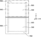
- the pair of guide portions 563 includes an accommodation position (a position indicated by a broken line in FIGS. 7 and 8) where the placement portion 562 is located in the cooler frame body 561, and a placement portion 562 outside the cooler frame body 561.
- the placement portion 562 may be displaced with respect to the cooler frame 561 along the width direction (Y direction) between the exposure position (the position indicated by the two-dot chain line in FIGS. 7 and 8). It is configured to be able to.
- each guide portion 563 includes a first guide rail fixed to the cooler frame 561 and a second guide rail fixed to the placement portion 562.
- the second guide rail is provided at an end portion in the width direction (X direction) of the placement portion 562 and can be displaced along the first guide rail.
- the brine flow path 240 is configured by an expandable / contractible pipe. Moreover, it is preferable that at least a part between the compression part 32 and the heat exchanger 331 and a part between the heat exchanger 331 and the expansion part 34 in the refrigerant flow path 30 are also configured by the expansion pipe.
- Each telescopic pipe extends to allow the placement portion 562 to be displaced from the accommodation position to the exposure position. In this way, the mounting portion 562 is positioned at the exposed position without dividing the brine flow path 240 and the refrigerant flow path 30 through the window formed in the cover disposed around the cooler frame 561. be able to.
- a shutoff valve is provided in the brine flow path 240, and the brine flow path 240 is divided in a state in which the brine flow out from the brine flow path 240 is prevented by closing the shutoff valve, so that the mounting portion 562 is disposed at the exposed position. You may pull out. The same applies to the refrigerant flow path 30 side.
- the precool heat exchanger 242 may be provided outside the dispenser 11.
- the precool heat exchanger 242 may be accommodated in the cooler accommodating body 56.
- the brine pump 241 and the brine tank may be disposed outside the cooler container 56 as long as at least the expansion unit 34, the compression unit 32, and the evaporation unit 31 are stored in the cooler container 56.
- a housing for housing each device of the brine circuit 5 may be provided. The housing is independent of the cooler housing 56 and includes the compressor unit 21, the accumulator unit 23, and the like. It may be connected to the dispenser 11.
- the cooler unit 24 may cool the hydrogen gas immediately before flowing into the dispenser 11.
- the compressor unit 21, the accumulator unit 23, and the cooler unit 24 among the main devices have a particularly large configuration. Therefore, the compressor housing 51, the accumulator housing 53, and the cooler housing 56 are mutually connected. By being detachable, the degree of freedom of installation of the gas supply system 2 in the site can be improved.
- the number of pressure accumulators may be a number other than three.
- a cooling fluid other than water may be used as a cooling fluid for cooling the hydrogen gas.
- the compressor frame body 511, the cooler frame body 561, the pressure accumulator frame body 531 and the control unit frame body may be detachably connected to each other using a fastening member such as a binding member in addition to the fixture 290.
- the gas supply system 2 may be used for filling hydrogen gas into tank mounting devices other than vehicles.
- the gas supply system 2 may be used for supplying a gas other than hydrogen gas.
- cooler unit 24 may be configured with only the refrigerator 26 (that is, without the brine circuit 5).
- the dispenser 11 may be arranged apart from each unit 21, 23, 24.
- pressure accumulators 231 may be arranged separately from each other.
- a hydrogen generator that generates high-pressure hydrogen gas by electrolysis or the like may be used.
- the hydrogen station of the present embodiment includes a filling facility that fills a tank mounting device with a gas, and a gas supply system that supplies gas to the filling facility, and the gas supply system includes a compressor that compresses gas, A compressor housing that houses the compressor, and a refrigerator that cools the gas that has flowed into the filling facility or the gas just before it flows, and includes an evaporation section, an expansion section, and a compression section, A cooler housing that houses the evaporating unit, the expansion unit, and the compression unit, and the compressor housing and the cooler housing are detachable from each other.
- the gas supply system stores a gas discharged from the compressor, and stores a plurality of pressure accumulators that send the gas to the filling facility and a pressure accumulator housing that accommodates the plurality of pressure accumulators. It is preferable that the compressor housing, the pressure accumulator housing, and the cooler housing are detachable from each other.
- the compressor housing, the accumulator housing, and the cooler housing are integrated, and the compressor housing and the cooler housing are arranged on one side of the accumulator housing. It is preferable that they are arranged in line.
- the installation area of the hydrogen station can be reduced.
- the gas supply system further includes a receiving unit that receives the gas sucked into the compressor from the outside while reducing the pressure, and a receiving unit housing that houses the receiving unit, and the compression station
- the machine container and the receiving unit container are preferably detachable from each other.
- the size of the hydrogen station can be suppressed by integrating the compressor housing and the receiving unit housing.
- the plurality of pressure accumulators are arranged so as to overlap each other in the direction of gravity.
- the gas supply system is connected in parallel to each pressure accumulator, a reservoir tank that stores gas discharged from the compressor, each pressure accumulator from the compressor, and the A controller that controls the supply of the gas to the reservoir tank, the controller causing the compressor to supply the gas to the reservoir tank when the pressure of each accumulator is equal to or higher than a predetermined value. Is preferred.
- each accumulator when the pressure of each accumulator is a predetermined value (for example, a value when the accumulator is almost full of gas), the gas is stored in the reservoir tank. Is stored, that is, it is suppressed that an overload acts on each pressure accumulator.
- a predetermined value for example, a value when the accumulator is almost full of gas
- the cooler container is configured to expose the evaporation unit, the expansion unit, and the compression unit to the outside of the cooler container.
- the filling equipment and the pressure accumulator container are detachable from each other.
- a first assembly is formed by integrating the compressor housing and the cooler housing, and a second set is formed by integrating the pressure accumulator housing and the filling equipment. It is preferable that a solid body is formed, and the first assembly and the second assembly are arranged in a state of being separated from each other.
Abstract
Description
Claims (9)
- 水素ステーションであって、
タンク搭載装置へガスを充填する充填設備と、
前記充填設備にガスを供給するガス供給システムと、
を備え、
前記ガス供給システムは、
ガスを圧縮する圧縮機と、
前記圧縮機を収容する圧縮機収容体と、
前記充填設備に流入したガス、または、流入する直前のガスを冷却するための冷凍機であって蒸発部、膨張部及び圧縮部を含むものと、
前記蒸発部、前記膨張部及び前記圧縮部を収容するクーラ収容体と、
を含み、
前記圧縮機収容体及び前記クーラ収容体は、互いに着脱可能である、水素ステーション。 - 請求項1に記載の水素ステーションにおいて、
前記ガス供給システムは、
それぞれが前記圧縮機から吐出されたガスを貯留するとともに、前記充填設備にガスを送出する複数の蓄圧器と、
前記複数の蓄圧器を収容する蓄圧器収容体と、
をさらに備え、
前記圧縮機収容体、前記蓄圧器収容体及び前記クーラ収容体は、互いに着脱可能である、水素ステーション。 - 請求項2に記載の水素ステーションにおいて、
前記圧縮機収容体、前記蓄圧器収容体及び前記クーラ収容体が一体化されており、
前記圧縮機収容体及び前記クーラ収容体は、前記蓄圧器収容体の一の側部に沿って並ぶように配置されている、水素ステーション。 - 請求項1に記載の水素ステーションにおいて、
前記ガス供給システムは、
前記圧縮機に吸入されるガスを減圧しつつ外部から受け入れる受入ユニットと、
前記受入ユニットを収容する受入ユニット収容体と、
をさらに備え、
前記圧縮機収容体及び前記受入ユニット収容体は、互いに着脱可能である、水素ステーション。 - 請求項2に記載の水素ステーションにおいて、
前記複数の蓄圧器は、互いに重力方向に重なるように配置されている、水素ステーション。 - 請求項2に記載の水素ステーションにおいて、
前記ガス供給システムは、
各蓄圧器に対して並列に接続されており、前記圧縮機から吐出されたガスを貯留するリザーバタンクと、
前記圧縮機から各蓄圧器及び前記リザーバタンクへの前記ガスの供給を制御する制御部と、
をさらに備え、
前記制御部は、各蓄圧器の圧力が所定値以上のときに前記圧縮機から前記リザーバタンクへ前記ガスを供給させる、水素ステーション。 - 請求項1に記載の水素ステーションにおいて、
前記クーラ収容体は、前記蒸発部、前記膨張部及び前記圧縮部を当該クーラ収容体の外部に露出させることが可能に構成されている、水素ステーション。 - 請求項1に記載の水素ステーションにおいて、
前記充填設備及び前記蓄圧器収容体は、互いに着脱可能である、水素ステーション。 - 請求項8に記載の水素ステーションにおいて、
前記圧縮機収容体及び前記クーラ収容体が一体化することにより第1の組立体が形成されており、
前記蓄圧器収容体及び前記充填設備が一体化することにより第2の組立体が形成されており、
前記第1の組立体及び前記第2の組立体は、互いに離間した状態で配置されている、水素ステーション。
Priority Applications (5)
| Application Number | Priority Date | Filing Date | Title |
|---|---|---|---|
| CA2965772A CA2965772C (en) | 2014-10-31 | 2015-09-16 | Hydrogen station |
| US15/520,379 US10317011B2 (en) | 2014-10-31 | 2015-09-16 | Hydrogen station |
| EP15856051.6A EP3217064A4 (en) | 2014-10-31 | 2015-09-16 | Hydrogen station |
| KR1020177012396A KR101970904B1 (ko) | 2014-10-31 | 2015-09-16 | 수소 스테이션 |
| CN201580059302.9A CN107110430B (zh) | 2014-10-31 | 2015-09-16 | 加氢站 |
Applications Claiming Priority (4)
| Application Number | Priority Date | Filing Date | Title |
|---|---|---|---|
| JP2014222414 | 2014-10-31 | ||
| JP2014-222414 | 2014-10-31 | ||
| JP2015080057A JP6473033B2 (ja) | 2014-10-31 | 2015-04-09 | ガス供給システムおよび水素ステーション |
| JP2015-080057 | 2015-04-09 |
Publications (1)
| Publication Number | Publication Date |
|---|---|
| WO2016067780A1 true WO2016067780A1 (ja) | 2016-05-06 |
Family
ID=55857126
Family Applications (1)
| Application Number | Title | Priority Date | Filing Date |
|---|---|---|---|
| PCT/JP2015/076324 WO2016067780A1 (ja) | 2014-10-31 | 2015-09-16 | 水素ステーション |
Country Status (1)
| Country | Link |
|---|---|
| WO (1) | WO2016067780A1 (ja) |
Cited By (4)
| Publication number | Priority date | Publication date | Assignee | Title |
|---|---|---|---|---|
| WO2018104983A1 (en) | 2016-12-06 | 2018-06-14 | Air Liquide Japan Ltd. | Hydrogen refueling system |
| WO2018104982A1 (en) | 2016-12-06 | 2018-06-14 | Air Liquide Japan Ltd. | Hydrogen refueling system |
| EP3480459A1 (en) * | 2017-11-02 | 2019-05-08 | Kabushiki Kaisha Kobe Seiko Sho (Kobe Steel, Ltd.) | Gas supplying apparatus |
| EP3851316A1 (de) * | 2020-01-17 | 2021-07-21 | H2 Energy AG | System zum auftanken von fahrzeugen mit wasserstoff-elektrischem antrieb und zum aufladen von fahrzeugen mit batterie-elektrischem antrieb |
Citations (5)
| Publication number | Priority date | Publication date | Assignee | Title |
|---|---|---|---|---|
| JP2005024061A (ja) * | 2003-07-02 | 2005-01-27 | Air Water Inc | 移動式水素ステーションおよびその運転方法 |
| JP2009236270A (ja) * | 2008-03-28 | 2009-10-15 | Sinanen Co Ltd | 水素供給ステーションおよび水素供給方法 |
| JP2013024287A (ja) * | 2011-07-19 | 2013-02-04 | Taiyo Nippon Sanso Corp | 水素ガス充填装置 |
| JP2013167288A (ja) * | 2012-02-15 | 2013-08-29 | Taiyo Nippon Sanso Corp | 水素ステーション |
| JP2015158213A (ja) * | 2014-02-21 | 2015-09-03 | 株式会社神戸製鋼所 | ガス供給システムおよび水素ステーション |
-
2015
- 2015-09-16 WO PCT/JP2015/076324 patent/WO2016067780A1/ja active Application Filing
Patent Citations (5)
| Publication number | Priority date | Publication date | Assignee | Title |
|---|---|---|---|---|
| JP2005024061A (ja) * | 2003-07-02 | 2005-01-27 | Air Water Inc | 移動式水素ステーションおよびその運転方法 |
| JP2009236270A (ja) * | 2008-03-28 | 2009-10-15 | Sinanen Co Ltd | 水素供給ステーションおよび水素供給方法 |
| JP2013024287A (ja) * | 2011-07-19 | 2013-02-04 | Taiyo Nippon Sanso Corp | 水素ガス充填装置 |
| JP2013167288A (ja) * | 2012-02-15 | 2013-08-29 | Taiyo Nippon Sanso Corp | 水素ステーション |
| JP2015158213A (ja) * | 2014-02-21 | 2015-09-03 | 株式会社神戸製鋼所 | ガス供給システムおよび水素ステーション |
Non-Patent Citations (1)
| Title |
|---|
| See also references of EP3217064A4 * |
Cited By (12)
| Publication number | Priority date | Publication date | Assignee | Title |
|---|---|---|---|---|
| WO2018104983A1 (en) | 2016-12-06 | 2018-06-14 | Air Liquide Japan Ltd. | Hydrogen refueling system |
| WO2018104982A1 (en) | 2016-12-06 | 2018-06-14 | Air Liquide Japan Ltd. | Hydrogen refueling system |
| CN109964074A (zh) * | 2016-12-06 | 2019-07-02 | 乔治洛德方法研究和开发液化空气有限公司 | 氢气加注系统 |
| CN110036231A (zh) * | 2016-12-06 | 2019-07-19 | 乔治洛德方法研究和开发液化空气有限公司 | 加氢系统 |
| JP2020514629A (ja) * | 2016-12-06 | 2020-05-21 | 日本エア・リキード合同会社 | 水素燃料補給システム |
| US11079067B2 (en) | 2016-12-06 | 2021-08-03 | L'air Liquide Societe Anonyme Pour L'etude Et L'exploitation Des Procedes Georges Claude | Hydrogen refueling system |
| US11079069B2 (en) | 2016-12-06 | 2021-08-03 | L'air Liquide Societe Anonyme Pour L'etude Et L'exploitation Des Procedes Georges Claude | Hydrogen refueling system |
| CN109964074B (zh) * | 2016-12-06 | 2021-10-26 | 乔治洛德方法研究和开发液化空气有限公司 | 氢气加注系统 |
| EP3480459A1 (en) * | 2017-11-02 | 2019-05-08 | Kabushiki Kaisha Kobe Seiko Sho (Kobe Steel, Ltd.) | Gas supplying apparatus |
| KR20190050281A (ko) * | 2017-11-02 | 2019-05-10 | 가부시키가이샤 고베 세이코쇼 | 가스 공급 장치 |
| KR102130606B1 (ko) | 2017-11-02 | 2020-07-06 | 가부시키가이샤 고베 세이코쇼 | 가스 공급 장치 |
| EP3851316A1 (de) * | 2020-01-17 | 2021-07-21 | H2 Energy AG | System zum auftanken von fahrzeugen mit wasserstoff-elektrischem antrieb und zum aufladen von fahrzeugen mit batterie-elektrischem antrieb |
Similar Documents
| Publication | Publication Date | Title |
|---|---|---|
| JP6473033B2 (ja) | ガス供給システムおよび水素ステーション | |
| US10801671B2 (en) | Gas supply system and hydrogen station | |
| WO2016067780A1 (ja) | 水素ステーション | |
| JP6276160B2 (ja) | ガス供給システムおよび水素ステーション | |
| JP6276060B2 (ja) | ガス供給システムおよび水素ステーション | |
| WO2015125585A1 (ja) | ガス供給システムおよび水素ステーション | |
| KR102130606B1 (ko) | 가스 공급 장치 | |
| JP5661057B2 (ja) | 水素ステーション | |
| US10704284B2 (en) | Combustible gas supply unit and barrier | |
| JP6518291B2 (ja) | ガス供給システムおよび水素ステーション | |
| JP2019178771A (ja) | 水素ステーションパッケージユニットと簡易型水素ステーション | |
| TWI568638B (zh) | Installation of refrigerators for foodstuffs on ships and installation of refrigerators for food depots on ships | |
| CN109307149B (zh) | 可燃性气体供给组件以及加氢站 | |
| JP2019090501A (ja) | ガス供給装置 | |
| CN212296876U (zh) | 车载式散装水泥输送专用空压机 | |
| JP2001027485A (ja) | 冷却水の熱交換装置 |
Legal Events
| Date | Code | Title | Description |
|---|---|---|---|
| 121 | Ep: the epo has been informed by wipo that ep was designated in this application |
Ref document number: 15856051 Country of ref document: EP Kind code of ref document: A1 |
|
| WWE | Wipo information: entry into national phase |
Ref document number: 15520379 Country of ref document: US |
|
| ENP | Entry into the national phase |
Ref document number: 2965772 Country of ref document: CA |
|
| REEP | Request for entry into the european phase |
Ref document number: 2015856051 Country of ref document: EP |
|
| NENP | Non-entry into the national phase |
Ref country code: DE |
|
| ENP | Entry into the national phase |
Ref document number: 20177012396 Country of ref document: KR Kind code of ref document: A |