EP3551909B1 - Dispositif de préhension amélioré - Google Patents
Dispositif de préhension amélioré Download PDFInfo
- Publication number
- EP3551909B1 EP3551909B1 EP17817011.4A EP17817011A EP3551909B1 EP 3551909 B1 EP3551909 B1 EP 3551909B1 EP 17817011 A EP17817011 A EP 17817011A EP 3551909 B1 EP3551909 B1 EP 3551909B1
- Authority
- EP
- European Patent Office
- Prior art keywords
- channel
- gripping device
- gripping
- hole
- wall
- Prior art date
- Legal status (The legal status is an assumption and is not a legal conclusion. Google has not performed a legal analysis and makes no representation as to the accuracy of the status listed.)
- Active
Links
Images


Classifications
-
- F—MECHANICAL ENGINEERING; LIGHTING; HEATING; WEAPONS; BLASTING
- F16—ENGINEERING ELEMENTS AND UNITS; GENERAL MEASURES FOR PRODUCING AND MAINTAINING EFFECTIVE FUNCTIONING OF MACHINES OR INSTALLATIONS; THERMAL INSULATION IN GENERAL
- F16G—BELTS, CABLES, OR ROPES, PREDOMINANTLY USED FOR DRIVING PURPOSES; CHAINS; FITTINGS PREDOMINANTLY USED THEREFOR
- F16G11/00—Means for fastening cables or ropes to one another or to other objects; Caps or sleeves for fixing on cables or ropes
- F16G11/10—Quick-acting fastenings; Clamps holding in one direction only
- F16G11/105—Clamps holding in one direction only
- F16G11/106—Clamps holding in one direction only using a toothed surface
-
- F—MECHANICAL ENGINEERING; LIGHTING; HEATING; WEAPONS; BLASTING
- F16—ENGINEERING ELEMENTS AND UNITS; GENERAL MEASURES FOR PRODUCING AND MAINTAINING EFFECTIVE FUNCTIONING OF MACHINES OR INSTALLATIONS; THERMAL INSULATION IN GENERAL
- F16G—BELTS, CABLES, OR ROPES, PREDOMINANTLY USED FOR DRIVING PURPOSES; CHAINS; FITTINGS PREDOMINANTLY USED THEREFOR
- F16G11/00—Means for fastening cables or ropes to one another or to other objects; Caps or sleeves for fixing on cables or ropes
- F16G11/10—Quick-acting fastenings; Clamps holding in one direction only
- F16G11/105—Clamps holding in one direction only
- F16G11/108—Clamps holding in one direction only using a ball or a cylinder
Definitions
- the present invention relates to a gripping device, and in particular to a device for gripping an elongate strand of material such as a wire.
- Gripping devices are used in many applications. For example, joining together wire strands in fencing applications, to suspend an object from a wire, to suspend sports equipment, or to suspend objects from structural elements of a building.
- Gripping devices are known from GB2430234 and GB2524964 .
- a limitation associated with the known gripping devices, such as the DOBYGRIP TM is that the suspension wire must not be more than 60 degrees from the vertical as shown in Figure 1a , and when one gripping device 1 is used to support an object, as shown in Figures 1b and 1c , the inclusive angle A must not be greater than 60 degrees. This can cause problems when suspending objects since the object must be positioned a certain minimum distance X from the gripping device 1.
- Another limitation associated with the known gripping devices is that the load that can be supported reduces as the suspension wire vertical angle increases. For example at the maximum angle of 60 degrees to the vertical the safe working load that can be supported is typically reduced by 50%.
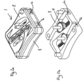
- Prior art devices comprise a body 3 and a top plate 2 as shown in Figures 2a and 2b .
- the square shaped aperture 4 for receiving a wire is formed by a three sided u-shaped channel in the body portion 3 of the device, which is then closed by securing the top plate 2 to the body 3. If the suspension wire is at an angle of more than 60 degrees to the vertical then the internal strain can cause the wire to be pulled away from the gear wheel 5 and can cause top plate 2 to be ripped away from the body 3, causing the device to fail.
- Gripping devices are also described in EP1967759 and US20130200637 .
- the wire is surrounded in part by a slot formed in the fitting which mounts the roller which engages the wire and in part by the outer casing of the device.
- the wires extend from the device at a wide angle forces are placed on the device which can pull apart the components thereof.
- the gripping device comprising:
- the channel is defined by channel walls and the channel wall opposing the gripping element is substantially straight.
- an elongate element located in the said channel is gripped between the gripping element and the substantially straight opposing channel wall of the channel.
- the channel is defined by channel walls and the channel wall opposing the gripping element includes two intersecting surfaces lying at an angle to one another, the angle between the two surfaced being concave.
- the angle between the two surfaces lies in the range 160 to 179 degrees.
- the holes may be substantially cylindrical in shape.
- the diameter of each hole is not more than 3mm larger than the diameter of the elongate element to be inserted therein.
- each end wall has an inner surface and an outer surface and wherein the continuous wall of each hole has at least one radiused or chamfered edge, one of the at least one radiused or chamfered edge being situated between the continuous wall of the hole through the end wall and the outer surface of the end wall in which the hole is situated.
- the continuous wall of each hole may have two radiused or chamfered edges, the second of the two radiuses or chamfered edges being situated between the continuous wall of the hole through the end wall and the inner surface of the end wall in which the hole is situated.
- the gripping element is preferably a pinion wheel.
- the pinion wheel is one of: smooth, toothed and roughened.
- the track is one of: smooth, roughened and toothed.
- the gripping device may further comprise biasing means arranged to bias the pinion into the path of the elongate opening.
- the biasing means may be a spring, which spring may be a compression spring.
- the gripping device may further comprise means for manual adjustment of the gripping means.
- the gripping device may comprise a body and and wherein the top plate is attachable to the body.
- the body is formed of metal.
- the body is formed by casting or moulding.
- the holes in the end walls may be formed by drilling.
- the body could be machined from a workpiece of suitable material, such as a metal.
- the gripping device of the invention provides an advantage over the prior art in that it can be used with inclusive angles of greater than 60 degrees. This allows items to be suspended much closer to the gripping device which is particularly useful in areas where space is limited.
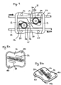
- the gripping device 10 of the invention comprises a body 12 and a top cover or plate 14.
- the body 12 includes a pair of channels 16 that extend through the body 12 from one side of the device to the other.
- the body 12 includes two solid end walls 13, and the longitudinal axis (B-B, Figure 5 ) of each channel 16 extends between the two end walls 13.
- Each of the end walls 13 have holes 18, 20 therethrough to allow access to the channels 16 through the walls 13.
- a first hole 18 is for receiving an elongate element such as a wire 22 (as shown in Fig 7 ) and a second hole 20 for where the wire 22 exits the device 10.
- the holes 18, 20 in the end walls are positioned within the wall such that the only access to the channels 16 is through the holes in the end walls.
- Each channel 16 has one substantially straight wall 30.
- the opposite side of the channel 16 includes a recess 34 which accommodates a gripping element in the form of a toothed pinion wheel 24 and a track 36.
- the pinion wheel 24 is mounted on a pin 28 having an upper end 28' and a lower end (not visible in the drawings).
- the body 12 is provided with a shaped cavity 31, in which the lower end of the pin 28 locates.
- the upper end 28' of the pin 28 extends through a slot 32 in the top plate 14, the shape of the slot 32 corresponds to the shape of the cavity 31.
- the extension of the upper end 28' of the pin 28 through the slot 32 in the top cover 14 provides a means by which the position of the pinion wheel 24 may be manually adjusted.
- the slot 32 and cavity 31 are positioned and oriented such that the teeth of the pinion wheel 24 engage with the track 36 of the recess 34.
- the ends of the slot 32 and cavity 31 define the extreme positions of the pinion wheel and the shape of the slot 32 and the cavity 31 define a path in which the pin 28 travels.
- the slot 32 and cavity 31 lie substantially parallel with the track 36, which is set at an acute angle to the longitudinal axis B-B of the channel 16.
- the end of the wire 22 is pushed into the body 13 of the device through the hole 18. in the direction of the arrow The wire 22 then pushes the pinion wheel 24 so that it travels along the path of the slot 32 and cavity 31, thereby allowing space for the wire to pass the pinion wheel 24 and exit through the opening 20.
- the spring 26 pushes the pinion wheel 24 against the surface of the wire 22 so that the teeth of the pinion wheel 24 grip the surface of the wire 22 causing the wire to abut firmly against the channel wall 30.
- the diameter of the wire is preferably matched to the diameter of the holes 18, 20 so that the hole 18, 20 is typically not more than 3mm larger than the diameter of the wire 22.
- the body includes location pins 38 which align with holes 40 in the top cover 14. As shown in Figure 8b , the underside of the top cover 14 includes two location pins 42 which align with holes 44 in the body 12. The location pins 38, 42 are a press fit into the holes 40, 44.
- the holes 18, 20 are preferably aligned with the channel wall 30, such that the wire 22 remains aligned with the wall 30 as it exits the device 10.
- the holes 18, 20 are not shaped or chamfered, however chamfered or radiused holes may be used to assist insertion of a wire and to provide other advantages as descried below with reference to Figures 11a and 11b .
- the channel wall need not be completely straight as illustrated in the embodiment of Figure 9 .
- the channel wall 30 with which a wire is aligned includes a slight bend indicated at 46.
- the bend 46 is preferably adjacent to the pinion wheel 24.
- the channel wall is made up of two surfaces 30' and 30" which intersect and lie at an angle to one another, preferably between 160 and 179 degrees.
- the track 36 may be smooth, roughened or toothed. In the illustrated embodiments, the track 36 is smooth.
- both the body and top plate are made from a cast metal, such as a zinc aluminium alloy.
- the device may be machined from a solid block of metal.
- the device is described as being formed as a two piece unit it may also be formed as a single-bodied device.
- Figure 11a illustrates an example of the gripping device 10 where the junction between the outer surface of the end wall 13 and the surface of the hole 20 formed in the wall is formed by a radius 20. Only hole 20 is illustrated, but the hole 18 in the same end wall 13 would be formed similarly with a radius 20'.
- the holes 18, 20 in the end walls 13 at each end of the gripping device 10 may be provided with radiuses 20', however the radiuses 20' are most important at the end of the gripping device proximate the item that is to be suspended since it is from this end that the wires extend at a large included angle.
- the radius 11' is replaced by a chamfered edge 20". This is preferably to an vertex.
- a vertex exerts a load on the wire at a single point, whereas chamfered edge 20" spreads the load over two points on the wire.
- a radius spreads the load over the surface of the radius. The radiused edge 20' is preferred for this reason.
- a suspension wire By forming the body 12 of the gripping device 10 with solid end walls with holes 18, 20 therein to access the channels 16 it is possible for a suspension wire to be used at a much greater angles as shown in Fig 10 . Since the wire 22 is held in place within the solid end wall 13 the device does not fail at larger inclusive angles. As shown in Figure 10 , using the gripping device of the invention 10, a duct or pipe 50 can be raised a distance Y when compared to use of a prior art griping device 1 in which a maximum inclusive angle of 60 degrees is required. This is particularly useful in situations where space is of a premium.
Landscapes
- Engineering & Computer Science (AREA)
- General Engineering & Computer Science (AREA)
- Mechanical Engineering (AREA)
- Manipulator (AREA)
Claims (14)
- Un dispositif de préhension (10) comprenant :un corps (12) et une plaque supérieure (14), la plaque supérieure (14) pouvant être fixée au corps (12), le corps incluant un ou plusieurs canaux allongés (16) pour recevoir un élément allongé (22), le ou les canaux allongés (16) ayant un axe longitudinal ;un élément de préhension (24) ; etun moyen de sollicitation (26) pour amener l'élément de préhension (24) en prise avec un élément allongé (22) situé dans ledit canal (16) ;dans lequel l'élément de préhension (24) est monté pour un mouvement de translation dans une fente (31) formée dans le corps (12), la fente (31) ayant un axe longitudinal, et l'axe longitudinal de la fente (31) est placé à un angle aigu par rapport à l'axe longitudinal du canal (16) ;dans lequel une composante de force exercée sur un élément allongé (22) situé dans ledit canal (16) amène l'élément de préhension (24) à se déplacer dans la fente (31) vers l'élément allongé (22) ;caractérisé en ce que le corps (12) a des première et deuxième extrémités et inclut deux parois d'extrémité pleines espacées (13), une paroi d'extrémité étant située à la première extrémité du corps et l'autre paroi d'extrémité étant située à la deuxième extrémité du corps, et l'axe longitudinal du ou des canaux (16) s'étend entre les deux parois d'extrémité (13) ; etdans lequel chaque paroi d'extrémité (13) inclut un ou plusieurs trous (18, 20) traversants, alignés avec un des canaux allongés (16), un premier trou (18) pour la réception d'un élément allongé (22) dans ledit canal (16) et un deuxième trou (20) pour la sortie dudit élément allongé (22) dudit canal (16), et dans lequel chaque trou (18, 20) est défini par une paroi continue, la paroi continue comprenant une partie de la paroi d'extrémité pleine.
- Un dispositif de préhension selon la revendication 1, dans lequel le canal (16) est défini par des parois de canal (30) et dans lequel la paroi de canal (30) opposée à l'élément de préhension (24) est sensiblement droite et dans lequel, lors de l'utilisation, un élément allongé (22) situé dans ledit canal (16) est saisi entre l'élément de préhension (24) et la paroi de canal opposée sensiblement droite (30) du canal (16).
- Un dispositif de préhension selon la revendication 1, dans lequel le canal (16) est défini par des parois de canal (30) et dans lequel la paroi de canal opposée à l'élément de préhension inclut deux surfaces d'intersection (30', 30") placées en formant un angle l'une par rapport à l'autre, l'angle entre le deux surfaces étant concave.
- Un dispositif de préhension selon la revendication 3, dans lequel l'angle entre le deux surfaces (30', 30") est dans la plage de 160 to 179 degrés.
- Un dispositif de préhension selon l'une quelconque des revendications précédentes, dans lequel les trous (18, 20) sont de section transversale sensiblement circulaire fournissant une forme cylindrique.
- Un dispositif de préhension selon l'une quelconque des revendications précédentes, dans lequel le diamètre de chaque trou (18, 20) n'est pas plus de 3 mm plus grand que le diamètre de l'élément allongé (22) y étant introduit.
- Un dispositif de préhension selon l'une quelconque des revendications précédentes, dans lequel chaque paroi d'extrémité (13) a une surface intérieure et une surface extérieure et dans lequel la paroi continue de chaque trou (18, 20) a un ou plusieurs bords arrondis ou chanfreinés (20"), le ou les bords arrondis ou chanfreinés étant situés entre la paroi continue du trou (18, 20) à travers la paroi d'extrémité (13) et la surface extérieure de la paroi d'extrémité dans laquelle le trou (18, 20) est situé.
- Un dispositif de préhension selon la revendication 7, dans lequel la paroi continue de chaque trou (18, 20) a deux bords arrondis ou chanfreinés (20"), le deuxième des deux bords arrondis ou chanfreinés étant situé entre la paroi continue du trou (18, 20) à travers la paroi d'extrémité (13) et la surface intérieure de la paroi d'extrémité dans laquelle le trou (18, 20) est situé.
- Un dispositif de préhension selon l'une quelconque des revendications précédentes, dans lequel l'élément de préhension (24) est une roue pignon ; ou dans lequel l'élément de préhension est une roue pignon et la roue pignon est : soit lisse, soit rugueuse, soit dentée.
- Un dispositif de préhension selon la revendication 9, dans lequel une surface du canal fournit une crémaillère (36), la roue pignon se mettant en prise avec la crémaillère.
- Un dispositif de préhension selon la revendication 10, dans lequel la crémaillère (36) est : soit lisse, soit rugueuse, soit dentée.
- Un dispositif de préhension selon l'une quelconque des revendications précédentes, dans lequel le moyen de sollicitation (26) est un ressort.
- Un dispositif de préhension selon la revendication 12, dans lequel le ressort est un ressort de compression.
- Un dispositif de préhension selon l'une quelconque des revendications précédentes, comprenant en outre un moyen de réglage manuel du moyen de préhension.
Applications Claiming Priority (2)
| Application Number | Priority Date | Filing Date | Title |
|---|---|---|---|
| GBGB1620733.4A GB201620733D0 (en) | 2016-12-06 | 2016-12-06 | Improved gripping device |
| PCT/GB2017/053291 WO2018104697A1 (fr) | 2016-12-06 | 2017-11-01 | Dispositif de préhension amélioré |
Publications (3)
| Publication Number | Publication Date |
|---|---|
| EP3551909A1 EP3551909A1 (fr) | 2019-10-16 |
| EP3551909C0 EP3551909C0 (fr) | 2023-10-11 |
| EP3551909B1 true EP3551909B1 (fr) | 2023-10-11 |
Family
ID=58159568
Family Applications (1)
| Application Number | Title | Priority Date | Filing Date |
|---|---|---|---|
| EP17817011.4A Active EP3551909B1 (fr) | 2016-12-06 | 2017-11-01 | Dispositif de préhension amélioré |
Country Status (5)
| Country | Link |
|---|---|
| US (1) | US10935103B2 (fr) |
| EP (1) | EP3551909B1 (fr) |
| ES (1) | ES2967922T3 (fr) |
| GB (2) | GB201620733D0 (fr) |
| WO (1) | WO2018104697A1 (fr) |
Families Citing this family (9)
| Publication number | Priority date | Publication date | Assignee | Title |
|---|---|---|---|---|
| US12044040B2 (en) * | 2021-04-02 | 2024-07-23 | Brady Worldwide, Inc. | Cable lockout device |
| US20240301979A1 (en) * | 2021-07-23 | 2024-09-12 | Gripple Limited | Securing assembly |
| CA3228522A1 (fr) * | 2021-08-18 | 2023-02-23 | Samuel White | Dispositif de serrage |
| US12449066B2 (en) * | 2022-11-19 | 2025-10-21 | Easy Solar Products, Inc. | Locking apparatus with roller for wire management |
| USD1053001S1 (en) * | 2022-11-30 | 2024-12-03 | Gripple Limited | Fastening device |
| USD1052392S1 (en) * | 2022-11-30 | 2024-11-26 | Gripple Limited | Fastening device |
| USD1058359S1 (en) * | 2022-11-30 | 2025-01-21 | Gripple Limited | Fastening device |
| USD1082499S1 (en) * | 2023-01-06 | 2025-07-08 | Gripple Limited | Fastening device |
| GB2627449B (en) * | 2023-02-21 | 2025-03-05 | Tailfin Ltd | An anchor for securing an elastic cord |
Family Cites Families (7)
| Publication number | Priority date | Publication date | Assignee | Title |
|---|---|---|---|---|
| IT1107513B (it) * | 1978-10-26 | 1985-11-25 | Pal Di Dona Alessandro & C S N | Dispositivo autobloccante per corde,trecce,cavi e simili particolarmente sollecitati alla trazione |
| EP0386022B1 (fr) * | 1987-09-26 | 1995-04-19 | Gripple Limited | Serre fils |
| JPH11201237A (ja) * | 1997-12-23 | 1999-07-27 | Gripple Ltd | 器材吊り下げ方法 |
| GB2378213B (en) * | 2001-08-01 | 2004-01-14 | Gripple Ltd | Wire or like connectors/tensioners |
| US8578566B2 (en) * | 2007-10-31 | 2013-11-12 | Thomas & Betts International, Inc. | Cable gripping device |
| MX2011012421A (es) * | 2009-07-09 | 2012-01-25 | Gripple Ltd | Cables, conectores, etc. |
| GB2524964A (en) * | 2014-04-07 | 2015-10-14 | Doby Cleats Ltd | Improved gripping device |
-
2016
- 2016-12-06 GB GBGB1620733.4A patent/GB201620733D0/en not_active Ceased
-
2017
- 2017-11-01 WO PCT/GB2017/053291 patent/WO2018104697A1/fr not_active Ceased
- 2017-11-01 EP EP17817011.4A patent/EP3551909B1/fr active Active
- 2017-11-01 ES ES17817011T patent/ES2967922T3/es active Active
- 2017-11-01 US US16/466,687 patent/US10935103B2/en active Active
- 2017-12-05 GB GB1720239.1A patent/GB2562817B/en active Active
Also Published As
| Publication number | Publication date |
|---|---|
| EP3551909C0 (fr) | 2023-10-11 |
| GB201720239D0 (en) | 2018-01-17 |
| ES2967922T3 (es) | 2024-05-06 |
| US20190301567A1 (en) | 2019-10-03 |
| WO2018104697A1 (fr) | 2018-06-14 |
| GB2562817B (en) | 2022-01-05 |
| GB201620733D0 (en) | 2017-01-18 |
| EP3551909A1 (fr) | 2019-10-16 |
| GB2562817A (en) | 2018-11-28 |
| US10935103B2 (en) | 2021-03-02 |
Similar Documents
| Publication | Publication Date | Title |
|---|---|---|
| EP3551909B1 (fr) | Dispositif de préhension amélioré | |
| EP3129676B1 (fr) | Dispositif de saisie amélioré | |
| EP2447569B1 (fr) | Dispositif de préhension de câble | |
| US9604826B2 (en) | Low profile roller fairlead | |
| US6327753B1 (en) | Cable clamp | |
| EP3426946B1 (fr) | Support et système de support pour système d'étaiement d'oscillation de câble sismique et methode de former d'un support | |
| US9265989B2 (en) | Connecting adjustment assembly | |
| US9267571B2 (en) | Cable connector assembly | |
| EP2984245B1 (fr) | Dispositif de liaison parasismique pour liaison d'un panneau à une poutre | |
| US20170088150A1 (en) | Brake trolley and a brake system for a continuous belay system | |
| EP2912342B1 (fr) | Ensemble serrage | |
| US20240218943A1 (en) | Cable clamp with adjustment latches | |
| EP2630991A2 (fr) | Régleur de corde avec dispositif de remplacement rapide de corde | |
| WO2007117077A1 (fr) | Dispositif conçu pour fixer des objets à un plafond | |
| KR20180113816A (ko) | 전선볼트용 안전로프 고정장치 | |
| EP1746697B1 (fr) | Elément de fixation pour fixer une boîte à une canalisation à fils | |
| US8499608B2 (en) | Bending tool | |
| GB2378980A (en) | Suspension means | |
| DK1267092T3 (da) | Universalspændestykke til cylindrisk element, især til kabel | |
| WO2021033205A1 (fr) | Pince à coin | |
| JP3805730B2 (ja) | バー材への取着体 | |
| US20060081418A1 (en) | Ascender/descender | |
| JP2020002693A (ja) | アサガオ装置 | |
| JP5951735B2 (ja) | ケーブル架設用取付金具 | |
| KR101973400B1 (ko) | 와이어 로프 고정장치 및 이를 이용한 와이어 로프 고정방법 |
Legal Events
| Date | Code | Title | Description |
|---|---|---|---|
| STAA | Information on the status of an ep patent application or granted ep patent |
Free format text: STATUS: UNKNOWN |
|
| STAA | Information on the status of an ep patent application or granted ep patent |
Free format text: STATUS: THE INTERNATIONAL PUBLICATION HAS BEEN MADE |
|
| PUAI | Public reference made under article 153(3) epc to a published international application that has entered the european phase |
Free format text: ORIGINAL CODE: 0009012 |
|
| STAA | Information on the status of an ep patent application or granted ep patent |
Free format text: STATUS: REQUEST FOR EXAMINATION WAS MADE |
|
| 17P | Request for examination filed |
Effective date: 20190708 |
|
| AK | Designated contracting states |
Kind code of ref document: A1 Designated state(s): AL AT BE BG CH CY CZ DE DK EE ES FI FR GB GR HR HU IE IS IT LI LT LU LV MC MK MT NL NO PL PT RO RS SE SI SK SM TR |
|
| AX | Request for extension of the european patent |
Extension state: BA ME |
|
| DAV | Request for validation of the european patent (deleted) | ||
| DAX | Request for extension of the european patent (deleted) | ||
| STAA | Information on the status of an ep patent application or granted ep patent |
Free format text: STATUS: EXAMINATION IS IN PROGRESS |
|
| 17Q | First examination report despatched |
Effective date: 20210813 |
|
| GRAP | Despatch of communication of intention to grant a patent |
Free format text: ORIGINAL CODE: EPIDOSNIGR1 |
|
| STAA | Information on the status of an ep patent application or granted ep patent |
Free format text: STATUS: GRANT OF PATENT IS INTENDED |
|
| INTG | Intention to grant announced |
Effective date: 20230424 |
|
| GRAS | Grant fee paid |
Free format text: ORIGINAL CODE: EPIDOSNIGR3 |
|
| GRAA | (expected) grant |
Free format text: ORIGINAL CODE: 0009210 |
|
| STAA | Information on the status of an ep patent application or granted ep patent |
Free format text: STATUS: THE PATENT HAS BEEN GRANTED |
|
| AK | Designated contracting states |
Kind code of ref document: B1 Designated state(s): AL AT BE BG CH CY CZ DE DK EE ES FI FR GB GR HR HU IE IS IT LI LT LU LV MC MK MT NL NO PL PT RO RS SE SI SK SM TR |
|
| REG | Reference to a national code |
Ref country code: GB Ref legal event code: FG4D |
|
| REG | Reference to a national code |
Ref country code: CH Ref legal event code: EP |
|
| REG | Reference to a national code |
Ref country code: DE Ref legal event code: R096 Ref document number: 602017075270 Country of ref document: DE |
|
| REG | Reference to a national code |
Ref country code: IE Ref legal event code: FG4D |
|
| U01 | Request for unitary effect filed |
Effective date: 20231110 |
|
| U07 | Unitary effect registered |
Designated state(s): AT BE BG DE DK EE FI FR IT LT LU LV MT NL PT SE SI Effective date: 20240102 |
|
| U20 | Renewal fee for the european patent with unitary effect paid |
Year of fee payment: 7 Effective date: 20240131 |
|
| PG25 | Lapsed in a contracting state [announced via postgrant information from national office to epo] |
Ref country code: GR Free format text: LAPSE BECAUSE OF FAILURE TO SUBMIT A TRANSLATION OF THE DESCRIPTION OR TO PAY THE FEE WITHIN THE PRESCRIBED TIME-LIMIT Effective date: 20240112 |
|
| PG25 | Lapsed in a contracting state [announced via postgrant information from national office to epo] |
Ref country code: IS Free format text: LAPSE BECAUSE OF FAILURE TO SUBMIT A TRANSLATION OF THE DESCRIPTION OR TO PAY THE FEE WITHIN THE PRESCRIBED TIME-LIMIT Effective date: 20240211 |
|
| PG25 | Lapsed in a contracting state [announced via postgrant information from national office to epo] |
Ref country code: IS Free format text: LAPSE BECAUSE OF FAILURE TO SUBMIT A TRANSLATION OF THE DESCRIPTION OR TO PAY THE FEE WITHIN THE PRESCRIBED TIME-LIMIT Effective date: 20240211 Ref country code: GR Free format text: LAPSE BECAUSE OF FAILURE TO SUBMIT A TRANSLATION OF THE DESCRIPTION OR TO PAY THE FEE WITHIN THE PRESCRIBED TIME-LIMIT Effective date: 20240112 |
|
| REG | Reference to a national code |
Ref country code: ES Ref legal event code: FG2A Ref document number: 2967922 Country of ref document: ES Kind code of ref document: T3 Effective date: 20240506 |
|
| PG25 | Lapsed in a contracting state [announced via postgrant information from national office to epo] |
Ref country code: RS Free format text: LAPSE BECAUSE OF FAILURE TO SUBMIT A TRANSLATION OF THE DESCRIPTION OR TO PAY THE FEE WITHIN THE PRESCRIBED TIME-LIMIT Effective date: 20231011 Ref country code: PL Free format text: LAPSE BECAUSE OF FAILURE TO SUBMIT A TRANSLATION OF THE DESCRIPTION OR TO PAY THE FEE WITHIN THE PRESCRIBED TIME-LIMIT Effective date: 20231011 Ref country code: NO Free format text: LAPSE BECAUSE OF FAILURE TO SUBMIT A TRANSLATION OF THE DESCRIPTION OR TO PAY THE FEE WITHIN THE PRESCRIBED TIME-LIMIT Effective date: 20240111 Ref country code: HR Free format text: LAPSE BECAUSE OF FAILURE TO SUBMIT A TRANSLATION OF THE DESCRIPTION OR TO PAY THE FEE WITHIN THE PRESCRIBED TIME-LIMIT Effective date: 20231011 |
|
| REG | Reference to a national code |
Ref country code: CH Ref legal event code: PL |
|
| REG | Reference to a national code |
Ref country code: DE Ref legal event code: R097 Ref document number: 602017075270 Country of ref document: DE |
|
| PG25 | Lapsed in a contracting state [announced via postgrant information from national office to epo] |
Ref country code: CH Free format text: LAPSE BECAUSE OF NON-PAYMENT OF DUE FEES Effective date: 20231130 |
|
| PG25 | Lapsed in a contracting state [announced via postgrant information from national office to epo] |
Ref country code: CZ Free format text: LAPSE BECAUSE OF FAILURE TO SUBMIT A TRANSLATION OF THE DESCRIPTION OR TO PAY THE FEE WITHIN THE PRESCRIBED TIME-LIMIT Effective date: 20231011 |
|
| PG25 | Lapsed in a contracting state [announced via postgrant information from national office to epo] |
Ref country code: SK Free format text: LAPSE BECAUSE OF FAILURE TO SUBMIT A TRANSLATION OF THE DESCRIPTION OR TO PAY THE FEE WITHIN THE PRESCRIBED TIME-LIMIT Effective date: 20231011 |
|
| PG25 | Lapsed in a contracting state [announced via postgrant information from national office to epo] |
Ref country code: SM Free format text: LAPSE BECAUSE OF FAILURE TO SUBMIT A TRANSLATION OF THE DESCRIPTION OR TO PAY THE FEE WITHIN THE PRESCRIBED TIME-LIMIT Effective date: 20231011 Ref country code: SK Free format text: LAPSE BECAUSE OF FAILURE TO SUBMIT A TRANSLATION OF THE DESCRIPTION OR TO PAY THE FEE WITHIN THE PRESCRIBED TIME-LIMIT Effective date: 20231011 Ref country code: RO Free format text: LAPSE BECAUSE OF FAILURE TO SUBMIT A TRANSLATION OF THE DESCRIPTION OR TO PAY THE FEE WITHIN THE PRESCRIBED TIME-LIMIT Effective date: 20231011 Ref country code: CZ Free format text: LAPSE BECAUSE OF FAILURE TO SUBMIT A TRANSLATION OF THE DESCRIPTION OR TO PAY THE FEE WITHIN THE PRESCRIBED TIME-LIMIT Effective date: 20231011 Ref country code: CH Free format text: LAPSE BECAUSE OF NON-PAYMENT OF DUE FEES Effective date: 20231130 |
|
| PLBE | No opposition filed within time limit |
Free format text: ORIGINAL CODE: 0009261 |
|
| STAA | Information on the status of an ep patent application or granted ep patent |
Free format text: STATUS: NO OPPOSITION FILED WITHIN TIME LIMIT |
|
| PG25 | Lapsed in a contracting state [announced via postgrant information from national office to epo] |
Ref country code: MC Free format text: LAPSE BECAUSE OF FAILURE TO SUBMIT A TRANSLATION OF THE DESCRIPTION OR TO PAY THE FEE WITHIN THE PRESCRIBED TIME-LIMIT Effective date: 20231011 |
|
| PG25 | Lapsed in a contracting state [announced via postgrant information from national office to epo] |
Ref country code: MC Free format text: LAPSE BECAUSE OF FAILURE TO SUBMIT A TRANSLATION OF THE DESCRIPTION OR TO PAY THE FEE WITHIN THE PRESCRIBED TIME-LIMIT Effective date: 20231011 |
|
| 26N | No opposition filed |
Effective date: 20240712 |
|
| U21 | Renewal fee for the european patent with unitary effect paid with additional fee |
Year of fee payment: 8 Effective date: 20250530 |
|
| PG25 | Lapsed in a contracting state [announced via postgrant information from national office to epo] |
Ref country code: CY Free format text: LAPSE BECAUSE OF FAILURE TO SUBMIT A TRANSLATION OF THE DESCRIPTION OR TO PAY THE FEE WITHIN THE PRESCRIBED TIME-LIMIT; INVALID AB INITIO Effective date: 20171101 |
|
| PG25 | Lapsed in a contracting state [announced via postgrant information from national office to epo] |
Ref country code: HU Free format text: LAPSE BECAUSE OF FAILURE TO SUBMIT A TRANSLATION OF THE DESCRIPTION OR TO PAY THE FEE WITHIN THE PRESCRIBED TIME-LIMIT; INVALID AB INITIO Effective date: 20171101 |
|
| PG25 | Lapsed in a contracting state [announced via postgrant information from national office to epo] |
Ref country code: TR Free format text: LAPSE BECAUSE OF FAILURE TO SUBMIT A TRANSLATION OF THE DESCRIPTION OR TO PAY THE FEE WITHIN THE PRESCRIBED TIME-LIMIT Effective date: 20231011 |
|
| U20 | Renewal fee for the european patent with unitary effect paid |
Year of fee payment: 9 Effective date: 20251201 |
|
| PGFP | Annual fee paid to national office [announced via postgrant information from national office to epo] |
Ref country code: GB Payment date: 20251231 Year of fee payment: 9 |
|
| PGFP | Annual fee paid to national office [announced via postgrant information from national office to epo] |
Ref country code: IE Payment date: 20251201 Year of fee payment: 9 |
|
| PGFP | Annual fee paid to national office [announced via postgrant information from national office to epo] |
Ref country code: ES Payment date: 20251201 Year of fee payment: 9 |