EP3551881B1 - Bürstenanordnung - Google Patents
Bürstenanordnung Download PDFInfo
- Publication number
- EP3551881B1 EP3551881B1 EP17808787.0A EP17808787A EP3551881B1 EP 3551881 B1 EP3551881 B1 EP 3551881B1 EP 17808787 A EP17808787 A EP 17808787A EP 3551881 B1 EP3551881 B1 EP 3551881B1
- Authority
- EP
- European Patent Office
- Prior art keywords
- brush
- canopy
- bracket
- arrangement
- access opening
- Prior art date
- Legal status (The legal status is an assumption and is not a legal conclusion. Google has not performed a legal analysis and makes no representation as to the accuracy of the status listed.)
- Active
Links
Images

Classifications
-
- F—MECHANICAL ENGINEERING; LIGHTING; HEATING; WEAPONS; BLASTING
- F03—MACHINES OR ENGINES FOR LIQUIDS; WIND, SPRING, OR WEIGHT MOTORS; PRODUCING MECHANICAL POWER OR A REACTIVE PROPULSIVE THRUST, NOT OTHERWISE PROVIDED FOR
- F03D—WIND MOTORS
- F03D80/00—Details, components or accessories not provided for in groups F03D1/00 - F03D17/00
- F03D80/30—Lightning protection
-
- H—ELECTRICITY
- H01—ELECTRIC ELEMENTS
- H01R—ELECTRICALLY-CONDUCTIVE CONNECTIONS; STRUCTURAL ASSOCIATIONS OF A PLURALITY OF MUTUALLY-INSULATED ELECTRICAL CONNECTING ELEMENTS; COUPLING DEVICES; CURRENT COLLECTORS
- H01R39/00—Rotary current collectors, distributors or interrupters
- H01R39/02—Details for dynamo electric machines
- H01R39/38—Brush holders
- H01R39/383—Brush holders characterised by the electrical connection to the brush holder
-
- H—ELECTRICITY
- H01—ELECTRIC ELEMENTS
- H01R—ELECTRICALLY-CONDUCTIVE CONNECTIONS; STRUCTURAL ASSOCIATIONS OF A PLURALITY OF MUTUALLY-INSULATED ELECTRICAL CONNECTING ELEMENTS; COUPLING DEVICES; CURRENT COLLECTORS
- H01R39/00—Rotary current collectors, distributors or interrupters
- H01R39/64—Devices for uninterrupted current collection
-
- H—ELECTRICITY
- H01—ELECTRIC ELEMENTS
- H01R—ELECTRICALLY-CONDUCTIVE CONNECTIONS; STRUCTURAL ASSOCIATIONS OF A PLURALITY OF MUTUALLY-INSULATED ELECTRICAL CONNECTING ELEMENTS; COUPLING DEVICES; CURRENT COLLECTORS
- H01R43/00—Apparatus or processes specially adapted for manufacturing, assembling, maintaining, or repairing of line connectors or current collectors or for joining electric conductors
- H01R43/14—Maintenance of current collectors, e.g. reshaping of brushes, cleaning of commutators
-
- H—ELECTRICITY
- H02—GENERATION; CONVERSION OR DISTRIBUTION OF ELECTRIC POWER
- H02K—DYNAMO-ELECTRIC MACHINES
- H02K11/00—Structural association of dynamo-electric machines with electric components or with devices for shielding, monitoring or protection
- H02K11/40—Structural association with grounding devices
-
- H—ELECTRICITY
- H02—GENERATION; CONVERSION OR DISTRIBUTION OF ELECTRIC POWER
- H02K—DYNAMO-ELECTRIC MACHINES
- H02K5/00—Casings; Enclosures; Supports
- H02K5/04—Casings or enclosures characterised by the shape, form or construction thereof
- H02K5/14—Means for supporting or protecting brushes or brush holders
-
- H—ELECTRICITY
- H02—GENERATION; CONVERSION OR DISTRIBUTION OF ELECTRIC POWER
- H02K—DYNAMO-ELECTRIC MACHINES
- H02K7/00—Arrangements for handling mechanical energy structurally associated with dynamo-electric machines, e.g. structural association with mechanical driving motors or auxiliary dynamo-electric machines
- H02K7/18—Structural association of electric generators with mechanical driving motors, e.g. with turbines
- H02K7/1807—Rotary generators
- H02K7/1823—Rotary generators structurally associated with turbines or similar engines
- H02K7/183—Rotary generators structurally associated with turbines or similar engines wherein the turbine is a wind turbine
- H02K7/1838—Generators mounted in a nacelle or similar structure of a horizontal axis wind turbine
-
- H—ELECTRICITY
- H01—ELECTRIC ELEMENTS
- H01R—ELECTRICALLY-CONDUCTIVE CONNECTIONS; STRUCTURAL ASSOCIATIONS OF A PLURALITY OF MUTUALLY-INSULATED ELECTRICAL CONNECTING ELEMENTS; COUPLING DEVICES; CURRENT COLLECTORS
- H01R39/00—Rotary current collectors, distributors or interrupters
- H01R39/02—Details for dynamo electric machines
- H01R39/18—Contacts for co-operation with commutator or slip-ring, e.g. contact brush
- H01R39/20—Contacts for co-operation with commutator or slip-ring, e.g. contact brush characterised by the material thereof
-
- H—ELECTRICITY
- H01—ELECTRIC ELEMENTS
- H01R—ELECTRICALLY-CONDUCTIVE CONNECTIONS; STRUCTURAL ASSOCIATIONS OF A PLURALITY OF MUTUALLY-INSULATED ELECTRICAL CONNECTING ELEMENTS; COUPLING DEVICES; CURRENT COLLECTORS
- H01R39/00—Rotary current collectors, distributors or interrupters
- H01R39/02—Details for dynamo electric machines
- H01R39/18—Contacts for co-operation with commutator or slip-ring, e.g. contact brush
- H01R39/26—Solid sliding contacts, e.g. carbon brush
-
- H—ELECTRICITY
- H01—ELECTRIC ELEMENTS
- H01R—ELECTRICALLY-CONDUCTIVE CONNECTIONS; STRUCTURAL ASSOCIATIONS OF A PLURALITY OF MUTUALLY-INSULATED ELECTRICAL CONNECTING ELEMENTS; COUPLING DEVICES; CURRENT COLLECTORS
- H01R39/00—Rotary current collectors, distributors or interrupters
- H01R39/02—Details for dynamo electric machines
- H01R39/38—Brush holders
- H01R39/385—Means for mechanical fixation of the brush holder
-
- Y—GENERAL TAGGING OF NEW TECHNOLOGICAL DEVELOPMENTS; GENERAL TAGGING OF CROSS-SECTIONAL TECHNOLOGIES SPANNING OVER SEVERAL SECTIONS OF THE IPC; TECHNICAL SUBJECTS COVERED BY FORMER USPC CROSS-REFERENCE ART COLLECTIONS [XRACs] AND DIGESTS
- Y02—TECHNOLOGIES OR APPLICATIONS FOR MITIGATION OR ADAPTATION AGAINST CLIMATE CHANGE
- Y02E—REDUCTION OF GREENHOUSE GAS [GHG] EMISSIONS, RELATED TO ENERGY GENERATION, TRANSMISSION OR DISTRIBUTION
- Y02E10/00—Energy generation through renewable energy sources
- Y02E10/70—Wind energy
- Y02E10/72—Wind turbines with rotation axis in wind direction
Definitions
- the invention describes a brush arrangement of a wind turbine lightning protection system; a wind turbine; and a method of performing a maintenance procedure on such a brush arrangement.
- An example of a known brush arrangement is disclosed in WO2011/131205 .
- a wind turbine is vulnerable to lightning strikes on account of its construction, and also on account of its generally isolated position.
- a wind turbine can be hit many times, and therefore generally comprises a lightning protection system (LPS) to safely divert the very large lightning currents to ground.
- LPS lightning protection system
- a lightning strike can hit a wind turbine at any point, typically at the rotor blades, since these are the most exposed parts. Since the hub is connected to a main shaft or low-speed shaft of the generator assembly, it is important to design the wind turbine LPS to ensure that lightning current is diverted to ground and does not damage the generator. It is relatively straightforward to provide an electrical connection from the canopy to a bedframe (which supports the generator assembly), and then via down conductors through the tower to ground.
- a wind turbine LPS will therefore generally comprise a down conductor in each blade, continuing through to the hub and via one or more brushes through to the canopy and bedframe, and then via further down conductors through the tower to ground.
- the brush interface should always provide a path of least resistance from the hub to the canopy and bedframe.
- the uninterrupted electrical path is generally achieved by using one or more spring-loaded graphite "brushes".
- a brush assembly can be secured to the stationary part (e.g. the canopy) so that the brush is continually pressed against the rotatable part (a suitable surface of the rotating hub or the low-speed shaft to which the hub is connected).
- a brush will eventually wear down, and must be replaced.
- a bracket for holding the brush is mounted onto the outside front wall of the canopy. This arrangement requires a technician to enter the narrow and confined space in the spinner at the front of the wind turbine in order to install the brush and bracket, and again later on, in order to perform any maintenance steps.
- the brush arrangement of a wind turbine lightning protection system is realized to provide a current path from a hub to the canopy of the wind turbine, and comprises a brush holder arranged to hold a brush in electrical contact with a rotating contact surface at the exterior of the canopy, which contact surface is electrically connected to the hub; and a bracket arranged to electrically and physically connect the brush with a mounting plate, which is secured to the stationary canopy.
- the inventive brush arrangement is characterized by an access opening in the front wall of the canopy, which access opening is dimensioned to accommodate the bracket and brush holder; and by a mounting arrangement for securing the mounting plate to the canopy front wall - from within the canopy interior - over the access opening.
- An advantage of the inventive brush arrangement according to the invention is that it allows the quick and straightforward installation, inspection and replacement of a brush of an LPS bracket. Any such manoeuvre can be easily and quickly be carried out from within the canopy interior, which is significantly safer and roomier than the spinner, so that the risks and costs associated with such a manoeuvre can be favourably reduced.
- the "brush arrangement” or "brush assembly” is an element of the hub-to-canopy current path that electrically connects the blades and hub to electrical ground via the canopy and bedframe. Since the inventive brush arrangement can be regarded as a brush bracket of an LPS, the terms "brush arrangement” and “lightning brush bracket” are regarded as synonyms and may be used interchangeably.
- the wind turbine comprises a generator assembly arranged within a canopy, with a low-speed shaft, a gearbox for speed and torque conversion, and a high-speed shaft connected to the generator.
- a front end of the low-speed shaft assembly extends to the exterior of the canopy for connection to the hub.
- the wind turbine further comprises at least one brush arrangement of the type described above to provide a current path from the hub through the brush and then through the canopy, bedframe and then through the tower to electrical ground.
- the method of performing a maintenance procedure on the brush of such a brush arrangement comprises the steps of dismounting the mounting plate from the canopy front wall from within the canopy interior to expose the access opening; drawing the bracket and brush holder through the access opening; inspecting and/or replacing the brush of the brush arrangement; inserting the bracket and brush holder through the access opening; and then once again, from within the canopy interior, securing the mounting plate to the canopy front wall over the access opening.
- An advantage of the inventive method is that the inspection and possible replacement of a brush of an LPS bracket can easily and quickly be carried out. There is no longer any need for a technician to enter the spinner for this purpose, and the technician is no longer exposed to the health and safety risks associated with entering into and moving about in the confined space of the spinner. Instead, the design of the inventive brush arrangement allows the technician to easily retrieve the brush bracket from within the interior of the canopy.
- the rotor hub of the wind turbine is rotatably joined to the low-speed shaft that extends to a gearbox, which performs speed and torque conversion of a high-speed shaft that is connected to the generator.
- the canopy or nacelle serves to shield these and various other components from the environment, and the terms “canopy” and “nacelle” may be used interchangeably.
- the contact surface can be any surface of the rotating part of the wind turbine.
- the contact surface could be a surface of the hub.
- the contact surface is a surface of the front end of the main shaft that protrudes to the exterior of the canopy at the canopy front end, since this contact surface is closer to the canopy than the hub, allowing a more compact realization of a brush assembly.
- a wind turbine can comprise at least one of the inventive brush arrangements.
- a wind turbine comprises several such brush arrangements arranged essentially equidistantly about the hub/shaft interface.
- three or four lightning brush brackets spaced at equal intervals around the contact surface, can ensure that the electrical current is quickly and safely diverted to ground in the event of a lightning strike to the canopy.
- Using several such lightning brush brackets ensures a safe path to ground even if one or more of the brushes is worn and in need of replacement.
- a brush is held in a brush holder, which in turn is mounted to the bracket.
- the brush holder is preferably constructed to continually exert a force on the brush, thereby pressing the brush against the contact surface.
- the brush is effectively spring-loaded.
- the brush holder, any spring-loading mechanism, and a connector wire are generally supplied as a single unit, and can be mounted to any appropriate holder by means of the connector wire.
- the brush is generally constructed to carry large currents, and its connector wire will have a correspondingly large diameter or cross-sectional area.
- the bracket comprises a connector assembly adapted to electrically connect the brush to the bracket by means of the connector wire.
- the connector wire can terminate in an O-shaped or C-shaped tab in order to engage with a bolt.
- the connector assembly of the inventive lightning brush bracket is preferably realized to clamp the tab (mounted at the end of the connector wire) between the bracket and a fastener.
- a bracket may generally need to be manufactured to suit a specific kind of brush assembly chosen for a specific LPS application.
- the bracket is essentially an interface between the brush assembly and the LPS in which it will be used.
- the bracket comprises an elongate slit that extends away from the brush holder and is arranged to accommodate various connecting wire lengths (and therefore various types of brush holder assembly).
- the elongate slit is preferably shaped to accommodate a fastener for clamping the tab to the bracket.
- the inventive brush assembly - i.e. the bracket, the brush holder and the mounting plate - can easily by manoeuvred by a technician to either move the bracket and brush holder through the access opening and onto the other side of the canopy front wall, or to pull the bracket and brush holder through the access opening and into the canopy.
- the access opening need only be large enough to comfortably accommodate the bracket and the brush holder of the brush assembly.
- the dimensions of the brush assembly will therefore be determined largely by the size of the brush holder.
- the bracket and the mounting plate are preferably constructed so that, when the brush makes contact with the desired contact surface, the mounting plate lies against the inside surface of the canopy front wall.
- the bracket can have any shape that suitably joins the vertically oriented mounting plate and the brush holder.
- a lightning brush bracket may be designed to press its brush against the cylindrical outside surface of the main shaft (protruding through the front wall of the canopy).
- the plane of the canopy wall may therefore be regarded as being orthogonal to a plane of the electrical contact between brush and main shaft, and the bracket can be shaped appropriately to achieve the desired orientation of the brush.
- a curved bracket can achieve the desired connection, and its curved shape can facilitate ease of passage through the access opening, as will be explained with the aid of the diagrams.
- the mounting plate preferably completely covers the access opening, so that contaminants such as grease, dirt, and moisture can be prevented from passing between the spinner interior and the canopy interior.
- the access opening and the mounting plate each have a simple shape, for example circular or square, whereby the mounting plate is larger than the access opening to accommodate a suitable number of fasteners.
- a rectangular mounting plate can be secured to the canopy front wall by four bolts, with one bolt in each of the four corners, to engage with a complementary arrangement of weld nuts or blind rivet nuts previously fastened to the canopy front wall.
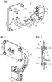
- Fig. 1 shows a first view of an embodiment of the inventive brush arrangement 1.
- the diagram shows a curved bracket 12 connecting a flat mounting plate 13 and a brush holder 11.
- the brush holder 11 is secured to the bracket 12 by means of bolts 110 as shown, and is shaped to hold a carbon or graphite brush 10 in a spring-loaded manner.
- a brush assembly comprising brush 10, connector wire 100, a spring-loading mechanism and a snap-fit element can be inserted into the brush holder 11, so that the entire assembly is securely contained and so that the brush 10 will be pushed against a contact surface for the duration of its useful lifetime.
- a tab 101 at the end of the connector wire 100 can be clamped between the bracket 12 and a fastener 120 to make a robust electrical connection between brush 10 and bracket 12.
- the bracket 12 has an elongate opening 121 to accommodate various lengths of connector wire 100, so that the bracket 12 can be used together with different types of brush assembly.
- the fastener 120 can be tightened to ensure a good electrical connection between the tab 101 and the bracket 12.
- All relevant components - e.g. connector wire 100, tab 101, bracket 12 and mounting plate 13 - are preferably made of an electrically conductive material such as stainless steel or copper.
- Fig. 2 shows another view of the inventive brush arrangement 1, and shows the tab 101 at the end of the connector wire 100 clamped between the bracket 12 and a fastener 120 to make a robust electrical connection between brush 10 and bracket 12.
- the bracket 12 could be formed in one piece with the mounting plate 13
- the bracket 12 is bolted to the mounting plate 13 using fasteners 121, and through-holes in the mounting plate 13 allow some positional adjustment of the bracket 12 to compensate for any tolerance between main shaft and canopy front.
- the bolts 123 are chosen to ensure a robust electrical connection between the bracket 12 and the mounting plate 13.
- the diagram shows part of the hub-to-canopy current path P which electrical current will follow in the event of a lightning strike to a blade or to the hub.
- the access opening 20 is smaller than the mounting plate 13, and the diagram also shows fixed nuts 132 such as weld nuts or blind rivets that have been permanently secured to the outside of the canopy front wall 21.
- the bracket 12 and brush holder 11 etc. are inserted through the access opening 20, until the mounting plate 13 lies against the inside surface of the canopy front wall 21.
- Bolts 131 are then inserted through matching and aligned through-holes or bushings in the mounting plate 13 and the canopy front wall 21, and tightened to secure the mounting plate 13 to the canopy front wall 21.
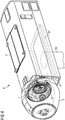
- Fig. 4 shows a spinner 3 mounted over a hub 4 at the front of a canopy 2 of a wind turbine 6.
- the drawing does not show the blades (which would be mounted to the hub through openings in the spinner) or the generator assembly but these may be assumed.
- the canopy 2 is mounted on top of a tower 60 via a yaw ring.
- the generator assembly is supported by a bedframe 61.
- the wind turbine may be assumed to comprise an LPS in which the canopy 2 is electrically connected to the bedframe 61, which in urn is connected to earth via down conductors through the tower 60.
- the LPS may further be assumed to comprise down conductors for the blades, in electrical contact to the hub 4.
- the hub 4 is mounted to the low-speed shaft 5 of the generator assembly by means of an annular arrangement of bolts securing a bolt ring 40 of the hub to the annular front end of the low-speed shaft 5, so that when wind causes the rotor blades to rotate, the hub 4 and generator main shaft 5 rotate accordingly.
- This diagram clearly indicates the very limited space available in the spinner 3, and gives an idea of the difficulty experienced by a technician whose task would be to perform a repair or maintenance task in that confined and hazardous space.
- the diagram indicates the position of two brush assemblies 1 electrically connecting the canopy 2 to the main shaft 5 of the generator.
- Fig. 5 shows a simplified view with fewer components, and clearly indicates the front end of the generator main shaft 5, and the contact surface 50 against which the brushes 10 of the lightning brush brackets 1 are pressed.
- the diagram also indicates access openings 20 formed in the front wall of the canopy 2, so that the lightning brush brackets 1 can be installed and maintained from the interior 22 of the canopy 2, thus avoiding any of the difficulties and risks associated with entering the spinner.
- the diagram also shows that such a wind turbine can easily be retro-fitted with lightning brush brackets 1 according to the invention, since the only modification would be to form access openings 20 in the canopy, and to detach and remove any existing brush assemblies of the conventional type.
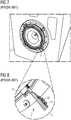
- Fig. 6 shows a more detailed view of the embodiment of Figs. 4 and 5 .
- the diagram shows the electrical connection between a brush 10 and a surface 50 of the low-speed shaft 5.
- the diagram also indicates the annular connection between the low-speed shaft 5 and a bolt ring 40 of the hub 4.
- the diagram allows the advantage of a curved bracket shape to be appreciated: when installing or removing the brush arrangement 1, the curved bracket shape allows the brush holder 11 to be manoeuvred in the confined space between hub ring 40 and canopy front wall 21 without being knocked or pressed against any surface, which might otherwise cause damage to the brush 10.
- space permitting, other more straightforward bracket shapes would be conceivable.
- Fig. 7 shows a prior art arrangement, in which brush assemblies 7 are mounted onto the front wall of the canopy 2.
- Fig. 8 A detail is shown in Fig. 8 , clearly showing the type of bracket 70 used in the conventional approach. This requires a matching mounting fitting 71 to be fastened to the canopy front wall 21.
- the skilled person To install this prior art brush assembly, or to perform a maintenance step, the skilled person must enter the confined space between spinner and hub, with all the attendant risks and difficulties.
Landscapes
- Engineering & Computer Science (AREA)
- Life Sciences & Earth Sciences (AREA)
- Sustainable Energy (AREA)
- Power Engineering (AREA)
- Sustainable Development (AREA)
- Chemical & Material Sciences (AREA)
- Combustion & Propulsion (AREA)
- Mechanical Engineering (AREA)
- General Engineering & Computer Science (AREA)
- Manufacturing & Machinery (AREA)
- Wind Motors (AREA)
Claims (9)
- Bürstenanordnung (1) für ein Windenergieanlagen-Blitzschutzsystem, die so umgesetzt ist, dass sie einen Stromweg (P) von einer Nabe (4) zu einem Gehäuse (2) der Windenergieanlage (6) bereitstellt, wobei die Bürstenanordnung (1) Folgendes umfasst:- einen Bürstenhalter (11), der so angeordnet ist, dass er eine Bürste (10) außen an dem Gehäuse (2) in elektrischem Kontakt mit einer Kontaktfläche (50) hält, die elektrisch mit der Nabe (4) verbunden ist,- eine Halterung (12), die so angeordnet ist, dass sie die Bürste (10) elektrisch mit einer Montageplatte (13) verbindet,gekennzeichnet durch- eine Zugangsöffnung (20) in der vorderen Wand (21) des Gehäuses (2), wobei die Zugangsöffnung (20) so bemessen ist, dass sie die Halterung (12) und den Bürstenhalter (11) aufnimmt, und- eine Montageanordnung zum Befestigen der Montageplatte (13) von der Gehäuseinnenseite (22) aus auf der Zugangsöffnung (20) an der vorderen Gehäusewand (21).
- Bürstenanordnung nach Anspruch 1, wobei die Halterung (12) eine Verbindungsstückbaugruppe (120, 121) umfasst, die so ausgelegt ist, dass sie die Bürste (10) elektrisch mit der Halterung (12) verbindet.
- Bürstenanordnung nach Anspruch 1 oder 2, wobei die Verbindungsstückbaugruppe (120, 121) so umgesetzt ist, dass sie zwischen der Halterung (12) und einem Befestigungsmittel (120) einen Bürstenverbindungsstück-Kabelschuh (101) festklemmt.
- Bürstenanordnung nach Anspruch 3, wobei die Verbindungsstückbaugruppe einen länglichen Schlitz (121) umfasst, der so angeordnet ist, dass er das Befestigungsmittel (120) aufnimmt.
- Bürstenanordnung nach einem der vorhergehenden Ansprüche, wobei die Oberfläche der Montageplatte (13) größer ist als die Zugangsöffnung (20).
- Bürstenanordnung nach einem der vorhergehenden Ansprüche, die eine Anordnung von Muttern (132) umfasst, welche zum Aufnehmen einer entsprechenden Anordnung von Bolzen (131), die durch die Montagehalterung und die vordere Gehäusewand (21) hindurchgeführt sind, an der Außenseite der vorderen Gehäusewand (21) angebracht sind.
- Windenergieanlage (6) mit einer Generatorbaugruppe, die von einer Grundplatte (61) in einem Gehäuse (2) getragen wird, wobei sich eine Kontaktfläche (50) einer langsamdrehenden Welle (5) der Generatorbaugruppe zur Verbindung mit einer Nabe (4) auf der Außenseite des Gehäuses (2) befindet, und ferner mit einem Blitzschutzsystem mit mindestens einer Bürstenanordnung (1) nach einem der Ansprüche 1 bis 6 zum Bereitstellen eines Stromwegs (P) von der Nabe (4) zum Gehäuse (2) .
- Windenergieanlage nach Anspruch 7, die vier Bürstenanordnungen (1) nach einem der Ansprüche 1 bis 6 umfasst, welche im Wesentlichen in gleichem Abstand um die Kontaktfläche (50) herum angeordnet sind.
- Verfahren zum Ausführen einer Wartungsmaßnahme an der Bürste (10) einer Bürstenanordnung (1) nach einem der Ansprüche 1 bis 6, das folgende Schritte umfasst:- Demontieren der Montageplatte (13) von der vorderen Gehäusewand (21) von der Gehäuseinnenseite (22) aus zum Freilegen der Zugangsöffnung (20),- Hindurchziehen der Halterung (12) und des Bürstenhalters (11) durch die Zugangsöffnung (20),- Überprüfen und/oder Austauschen der Bürste (10) der Bürstenanordnung (1),- Hindurchführen der Halterung (12) und des Bürstenhalters (11) durch die Zugangsöffnung (20) und- Befestigen der Montageplatte (13) von der Gehäuseinnenseite (22) aus auf der Zugangsöffnung (20) an der vorderen Gehäusewand (21).
Applications Claiming Priority (2)
| Application Number | Priority Date | Filing Date | Title |
|---|---|---|---|
| DE102017201107 | 2017-01-24 | ||
| PCT/EP2017/078681 WO2018137804A1 (en) | 2017-01-24 | 2017-11-09 | Brush arrangement |
Publications (2)
| Publication Number | Publication Date |
|---|---|
| EP3551881A1 EP3551881A1 (de) | 2019-10-16 |
| EP3551881B1 true EP3551881B1 (de) | 2020-10-21 |
Family
ID=60574525
Family Applications (1)
| Application Number | Title | Priority Date | Filing Date |
|---|---|---|---|
| EP17808787.0A Active EP3551881B1 (de) | 2017-01-24 | 2017-11-09 | Bürstenanordnung |
Country Status (5)
| Country | Link |
|---|---|
| US (1) | US11378064B2 (de) |
| EP (1) | EP3551881B1 (de) |
| CN (1) | CN110192029B (de) |
| DK (1) | DK3551881T3 (de) |
| WO (1) | WO2018137804A1 (de) |
Families Citing this family (2)
| Publication number | Priority date | Publication date | Assignee | Title |
|---|---|---|---|---|
| EP3664229A1 (de) * | 2018-12-06 | 2020-06-10 | Siemens Gamesa Renewable Energy A/S | Bürstenanordnung |
| CN111613947B (zh) * | 2020-04-21 | 2021-10-29 | 南京科之信机电科技有限公司 | 一种高空汇流环 |
Family Cites Families (13)
| Publication number | Priority date | Publication date | Assignee | Title |
|---|---|---|---|---|
| JPH0560053A (ja) | 1991-08-26 | 1993-03-09 | Mitsubishi Heavy Ind Ltd | 風 車 |
| ES2161196B1 (es) | 2000-05-09 | 2002-05-16 | Torres Disenos Ind S A M | Instalacion de pararrayos para aerogeneradores. |
| NZ546729A (en) * | 2003-11-20 | 2008-05-30 | Vestas Wind Sys As | Wind turbine lightning connection means method and use hereof |
| DE102004010104A1 (de) * | 2004-02-27 | 2005-09-29 | Repower Systems Ag | Blitzschutzeinrichtung für Windenergieanlagen |
| DK2110552T4 (en) * | 2008-04-15 | 2019-04-08 | Siemens Ag | Wind turbine blade with an integrated lightning arrester and method for manufacturing it |
| CN102652221B (zh) * | 2009-12-09 | 2016-10-12 | 西门子公司 | 用于风力涡轮机的防雷系统和具有防雷系统的风力涡轮机 |
| WO2011131205A1 (en) | 2010-04-19 | 2011-10-27 | Vestas Wind Systems A/S | Lightning current transfer unit, wind turbine, method and use thereof |
| EP2395238B1 (de) * | 2010-06-10 | 2014-04-02 | Siemens Aktiengesellschaft | Windturbine mit einem Blitzschutzsystem |
| CN103174603A (zh) | 2011-12-23 | 2013-06-26 | 新疆金风科技股份有限公司 | 一种风力发电机组防雷装置及风力发电机组 |
| CN103352808B (zh) | 2013-07-29 | 2016-02-03 | 南车株洲电力机车研究所有限公司 | 一种风机轮毂引雷导线的连接方法及引雷导线系统 |
| US10181767B2 (en) * | 2013-08-09 | 2019-01-15 | Black & Decker Inc. | Brush assembly with brush card mount with brush holders having base and main portion pieces |
| CN103603775B (zh) | 2013-11-22 | 2016-06-01 | 北京金风科创风电设备有限公司 | 防雷装置、直驱风力发电机组及其雷电防护方法 |
| EP3571399B1 (de) * | 2017-02-21 | 2022-06-15 | Siemens Gamesa Renewable Energy A/S | Windturbine mit einem erdungssystem zur übertragung von blitzstrom und zur bereitstellung von emf-abschirmung |
-
2017
- 2017-11-09 EP EP17808787.0A patent/EP3551881B1/de active Active
- 2017-11-09 CN CN201780084547.6A patent/CN110192029B/zh active Active
- 2017-11-09 WO PCT/EP2017/078681 patent/WO2018137804A1/en not_active Ceased
- 2017-11-09 DK DK17808787.0T patent/DK3551881T3/da active
- 2017-11-09 US US16/479,059 patent/US11378064B2/en active Active
Non-Patent Citations (1)
| Title |
|---|
| None * |
Also Published As
| Publication number | Publication date |
|---|---|
| CN110192029A (zh) | 2019-08-30 |
| CN110192029B (zh) | 2021-02-09 |
| DK3551881T3 (da) | 2020-11-23 |
| US20190368471A1 (en) | 2019-12-05 |
| US11378064B2 (en) | 2022-07-05 |
| EP3551881A1 (de) | 2019-10-16 |
| WO2018137804A1 (en) | 2018-08-02 |
Similar Documents
| Publication | Publication Date | Title |
|---|---|---|
| DE102007052525B4 (de) | Vorrichtung zum Ableiten eines Blitzes bei einer Windenergieanlage | |
| EP2789067B1 (de) | Blitzstromübertragungssystem für einen windturbinengenerator | |
| JP6333366B2 (ja) | 雷電流伝達システム及び雷電流伝達システムを用いる風力タービン | |
| EP2889477A1 (de) | Windturbinenrotor und windturbine | |
| DK2619447T3 (en) | LEAF CONNECTION OF A ROTOR BLADE IN A WINDOW ENERGY INSTALLATION | |
| US20120282097A1 (en) | Lightning protection system for a wind turbine, wind turbine and method for protecting components of a wind turbine against lightning strikes | |
| CN104364520B (zh) | 风力涡轮机叶片闪电旁路系统 | |
| CN105829710A (zh) | 具有火花隙的雷电电流传输系统及利用雷电电流传输系统的风轮机 | |
| WO2004001224A1 (en) | Lightning protection means for a wind turbine | |
| EP3551881B1 (de) | Bürstenanordnung | |
| EP3744972B1 (de) | Rotor für eine windturbine sowie windturbine | |
| EP2725220B1 (de) | Verfahren und system zum auswechseln eines einzelnen flügelblattes einer windkraftanlage | |
| CN105386943A (zh) | 风力发电机叶片叶尖避雷装置 | |
| EP3284948B1 (de) | Windkraftsystem zur erzeugung von elektrischer energie | |
| KR20140022545A (ko) | 낙뢰 보호 장치 및 이를 구비하는 풍력 발전기 | |
| EP3935280B1 (de) | Elektrische verbindungsvorrichtung für eine windturbine, windturbine und verfahren zur herstellung einer elektrischen verbindungsvorrichtung | |
| WO2011131205A1 (en) | Lightning current transfer unit, wind turbine, method and use thereof | |
| JP2008101587A (ja) | 風車ブレードの落雷保護装置 | |
| CN211287980U (zh) | 一种风力发电机组机舱罩防雷系统 | |
| KR101665892B1 (ko) | 풍력설비용 케이블 고정장치 | |
| EP4448956B1 (de) | Blitzaufnahmeanordnung | |
| EP3690238A1 (de) | Stromübertragungsanordnung eines blitzschutzsystems einer windturbine | |
| CN102946037A (zh) | 一种轮毂到机舱的雷电通道连接方法 |
Legal Events
| Date | Code | Title | Description |
|---|---|---|---|
| STAA | Information on the status of an ep patent application or granted ep patent |
Free format text: STATUS: UNKNOWN |
|
| STAA | Information on the status of an ep patent application or granted ep patent |
Free format text: STATUS: THE INTERNATIONAL PUBLICATION HAS BEEN MADE |
|
| PUAI | Public reference made under article 153(3) epc to a published international application that has entered the european phase |
Free format text: ORIGINAL CODE: 0009012 |
|
| STAA | Information on the status of an ep patent application or granted ep patent |
Free format text: STATUS: REQUEST FOR EXAMINATION WAS MADE |
|
| 17P | Request for examination filed |
Effective date: 20190712 |
|
| AK | Designated contracting states |
Kind code of ref document: A1 Designated state(s): AL AT BE BG CH CY CZ DE DK EE ES FI FR GB GR HR HU IE IS IT LI LT LU LV MC MK MT NL NO PL PT RO RS SE SI SK SM TR |
|
| DAV | Request for validation of the european patent (deleted) | ||
| GRAP | Despatch of communication of intention to grant a patent |
Free format text: ORIGINAL CODE: EPIDOSNIGR1 |
|
| STAA | Information on the status of an ep patent application or granted ep patent |
Free format text: STATUS: GRANT OF PATENT IS INTENDED |
|
| INTG | Intention to grant announced |
Effective date: 20200615 |
|
| GRAS | Grant fee paid |
Free format text: ORIGINAL CODE: EPIDOSNIGR3 |
|
| GRAA | (expected) grant |
Free format text: ORIGINAL CODE: 0009210 |
|
| STAA | Information on the status of an ep patent application or granted ep patent |
Free format text: STATUS: THE PATENT HAS BEEN GRANTED |
|
| AK | Designated contracting states |
Kind code of ref document: B1 Designated state(s): AL AT BE BG CH CY CZ DE DK EE ES FI FR GB GR HR HU IE IS IT LI LT LU LV MC MK MT NL NO PL PT RO RS SE SI SK SM TR |
|
| REG | Reference to a national code |
Ref country code: GB Ref legal event code: FG4D |
|
| REG | Reference to a national code |
Ref country code: CH Ref legal event code: EP |
|
| REG | Reference to a national code |
Ref country code: DE Ref legal event code: R096 Ref document number: 602017026046 Country of ref document: DE |
|
| REG | Reference to a national code |
Ref country code: IE Ref legal event code: FG4D |
|
| REG | Reference to a national code |
Ref country code: AT Ref legal event code: REF Ref document number: 1326093 Country of ref document: AT Kind code of ref document: T Effective date: 20201115 |
|
| REG | Reference to a national code |
Ref country code: DK Ref legal event code: T3 Effective date: 20201119 |
|
| REG | Reference to a national code |
Ref country code: AT Ref legal event code: MK05 Ref document number: 1326093 Country of ref document: AT Kind code of ref document: T Effective date: 20201021 |
|
| REG | Reference to a national code |
Ref country code: NL Ref legal event code: MP Effective date: 20201021 |
|
| PG25 | Lapsed in a contracting state [announced via postgrant information from national office to epo] |
Ref country code: FI Free format text: LAPSE BECAUSE OF FAILURE TO SUBMIT A TRANSLATION OF THE DESCRIPTION OR TO PAY THE FEE WITHIN THE PRESCRIBED TIME-LIMIT Effective date: 20201021 Ref country code: RS Free format text: LAPSE BECAUSE OF FAILURE TO SUBMIT A TRANSLATION OF THE DESCRIPTION OR TO PAY THE FEE WITHIN THE PRESCRIBED TIME-LIMIT Effective date: 20201021 Ref country code: PT Free format text: LAPSE BECAUSE OF FAILURE TO SUBMIT A TRANSLATION OF THE DESCRIPTION OR TO PAY THE FEE WITHIN THE PRESCRIBED TIME-LIMIT Effective date: 20210222 Ref country code: NO Free format text: LAPSE BECAUSE OF FAILURE TO SUBMIT A TRANSLATION OF THE DESCRIPTION OR TO PAY THE FEE WITHIN THE PRESCRIBED TIME-LIMIT Effective date: 20210121 Ref country code: GR Free format text: LAPSE BECAUSE OF FAILURE TO SUBMIT A TRANSLATION OF THE DESCRIPTION OR TO PAY THE FEE WITHIN THE PRESCRIBED TIME-LIMIT Effective date: 20210122 |
|
| REG | Reference to a national code |
Ref country code: LT Ref legal event code: MG4D |
|
| PG25 | Lapsed in a contracting state [announced via postgrant information from national office to epo] |
Ref country code: AT Free format text: LAPSE BECAUSE OF FAILURE TO SUBMIT A TRANSLATION OF THE DESCRIPTION OR TO PAY THE FEE WITHIN THE PRESCRIBED TIME-LIMIT Effective date: 20201021 Ref country code: ES Free format text: LAPSE BECAUSE OF FAILURE TO SUBMIT A TRANSLATION OF THE DESCRIPTION OR TO PAY THE FEE WITHIN THE PRESCRIBED TIME-LIMIT Effective date: 20201021 Ref country code: BG Free format text: LAPSE BECAUSE OF FAILURE TO SUBMIT A TRANSLATION OF THE DESCRIPTION OR TO PAY THE FEE WITHIN THE PRESCRIBED TIME-LIMIT Effective date: 20210121 Ref country code: SE Free format text: LAPSE BECAUSE OF FAILURE TO SUBMIT A TRANSLATION OF THE DESCRIPTION OR TO PAY THE FEE WITHIN THE PRESCRIBED TIME-LIMIT Effective date: 20201021 Ref country code: IS Free format text: LAPSE BECAUSE OF FAILURE TO SUBMIT A TRANSLATION OF THE DESCRIPTION OR TO PAY THE FEE WITHIN THE PRESCRIBED TIME-LIMIT Effective date: 20210221 Ref country code: LV Free format text: LAPSE BECAUSE OF FAILURE TO SUBMIT A TRANSLATION OF THE DESCRIPTION OR TO PAY THE FEE WITHIN THE PRESCRIBED TIME-LIMIT Effective date: 20201021 Ref country code: PL Free format text: LAPSE BECAUSE OF FAILURE TO SUBMIT A TRANSLATION OF THE DESCRIPTION OR TO PAY THE FEE WITHIN THE PRESCRIBED TIME-LIMIT Effective date: 20201021 |
|
| PG25 | Lapsed in a contracting state [announced via postgrant information from national office to epo] |
Ref country code: NL Free format text: LAPSE BECAUSE OF FAILURE TO SUBMIT A TRANSLATION OF THE DESCRIPTION OR TO PAY THE FEE WITHIN THE PRESCRIBED TIME-LIMIT Effective date: 20201021 Ref country code: HR Free format text: LAPSE BECAUSE OF FAILURE TO SUBMIT A TRANSLATION OF THE DESCRIPTION OR TO PAY THE FEE WITHIN THE PRESCRIBED TIME-LIMIT Effective date: 20201021 |
|
| REG | Reference to a national code |
Ref country code: CH Ref legal event code: PL |
|
| REG | Reference to a national code |
Ref country code: DE Ref legal event code: R097 Ref document number: 602017026046 Country of ref document: DE |
|
| PG25 | Lapsed in a contracting state [announced via postgrant information from national office to epo] |
Ref country code: SK Free format text: LAPSE BECAUSE OF FAILURE TO SUBMIT A TRANSLATION OF THE DESCRIPTION OR TO PAY THE FEE WITHIN THE PRESCRIBED TIME-LIMIT Effective date: 20201021 Ref country code: RO Free format text: LAPSE BECAUSE OF FAILURE TO SUBMIT A TRANSLATION OF THE DESCRIPTION OR TO PAY THE FEE WITHIN THE PRESCRIBED TIME-LIMIT Effective date: 20201021 Ref country code: MC Free format text: LAPSE BECAUSE OF FAILURE TO SUBMIT A TRANSLATION OF THE DESCRIPTION OR TO PAY THE FEE WITHIN THE PRESCRIBED TIME-LIMIT Effective date: 20201021 Ref country code: LT Free format text: LAPSE BECAUSE OF FAILURE TO SUBMIT A TRANSLATION OF THE DESCRIPTION OR TO PAY THE FEE WITHIN THE PRESCRIBED TIME-LIMIT Effective date: 20201021 Ref country code: LU Free format text: LAPSE BECAUSE OF NON-PAYMENT OF DUE FEES Effective date: 20201109 Ref country code: CZ Free format text: LAPSE BECAUSE OF FAILURE TO SUBMIT A TRANSLATION OF THE DESCRIPTION OR TO PAY THE FEE WITHIN THE PRESCRIBED TIME-LIMIT Effective date: 20201021 Ref country code: EE Free format text: LAPSE BECAUSE OF FAILURE TO SUBMIT A TRANSLATION OF THE DESCRIPTION OR TO PAY THE FEE WITHIN THE PRESCRIBED TIME-LIMIT Effective date: 20201021 Ref country code: SM Free format text: LAPSE BECAUSE OF FAILURE TO SUBMIT A TRANSLATION OF THE DESCRIPTION OR TO PAY THE FEE WITHIN THE PRESCRIBED TIME-LIMIT Effective date: 20201021 |
|
| REG | Reference to a national code |
Ref country code: BE Ref legal event code: MM Effective date: 20201130 |
|
| PLBE | No opposition filed within time limit |
Free format text: ORIGINAL CODE: 0009261 |
|
| STAA | Information on the status of an ep patent application or granted ep patent |
Free format text: STATUS: NO OPPOSITION FILED WITHIN TIME LIMIT |
|
| PG25 | Lapsed in a contracting state [announced via postgrant information from national office to epo] |
Ref country code: CH Free format text: LAPSE BECAUSE OF NON-PAYMENT OF DUE FEES Effective date: 20201130 Ref country code: LI Free format text: LAPSE BECAUSE OF NON-PAYMENT OF DUE FEES Effective date: 20201130 |
|
| 26N | No opposition filed |
Effective date: 20210722 |
|
| PG25 | Lapsed in a contracting state [announced via postgrant information from national office to epo] |
Ref country code: AL Free format text: LAPSE BECAUSE OF FAILURE TO SUBMIT A TRANSLATION OF THE DESCRIPTION OR TO PAY THE FEE WITHIN THE PRESCRIBED TIME-LIMIT Effective date: 20201021 Ref country code: IE Free format text: LAPSE BECAUSE OF NON-PAYMENT OF DUE FEES Effective date: 20201109 Ref country code: FR Free format text: LAPSE BECAUSE OF NON-PAYMENT OF DUE FEES Effective date: 20201221 Ref country code: IT Free format text: LAPSE BECAUSE OF FAILURE TO SUBMIT A TRANSLATION OF THE DESCRIPTION OR TO PAY THE FEE WITHIN THE PRESCRIBED TIME-LIMIT Effective date: 20201021 |
|
| PG25 | Lapsed in a contracting state [announced via postgrant information from national office to epo] |
Ref country code: SI Free format text: LAPSE BECAUSE OF FAILURE TO SUBMIT A TRANSLATION OF THE DESCRIPTION OR TO PAY THE FEE WITHIN THE PRESCRIBED TIME-LIMIT Effective date: 20201021 |
|
| PG25 | Lapsed in a contracting state [announced via postgrant information from national office to epo] |
Ref country code: IS Free format text: LAPSE BECAUSE OF FAILURE TO SUBMIT A TRANSLATION OF THE DESCRIPTION OR TO PAY THE FEE WITHIN THE PRESCRIBED TIME-LIMIT Effective date: 20210221 Ref country code: TR Free format text: LAPSE BECAUSE OF FAILURE TO SUBMIT A TRANSLATION OF THE DESCRIPTION OR TO PAY THE FEE WITHIN THE PRESCRIBED TIME-LIMIT Effective date: 20201021 Ref country code: MT Free format text: LAPSE BECAUSE OF FAILURE TO SUBMIT A TRANSLATION OF THE DESCRIPTION OR TO PAY THE FEE WITHIN THE PRESCRIBED TIME-LIMIT Effective date: 20201021 Ref country code: CY Free format text: LAPSE BECAUSE OF FAILURE TO SUBMIT A TRANSLATION OF THE DESCRIPTION OR TO PAY THE FEE WITHIN THE PRESCRIBED TIME-LIMIT Effective date: 20201021 |
|
| PG25 | Lapsed in a contracting state [announced via postgrant information from national office to epo] |
Ref country code: MK Free format text: LAPSE BECAUSE OF FAILURE TO SUBMIT A TRANSLATION OF THE DESCRIPTION OR TO PAY THE FEE WITHIN THE PRESCRIBED TIME-LIMIT Effective date: 20201021 |
|
| PG25 | Lapsed in a contracting state [announced via postgrant information from national office to epo] |
Ref country code: BE Free format text: LAPSE BECAUSE OF NON-PAYMENT OF DUE FEES Effective date: 20201130 |
|
| PGFP | Annual fee paid to national office [announced via postgrant information from national office to epo] |
Ref country code: DK Payment date: 20250901 Year of fee payment: 9 |
|
| PGFP | Annual fee paid to national office [announced via postgrant information from national office to epo] |
Ref country code: GB Payment date: 20250901 Year of fee payment: 9 |
|
| PGFP | Annual fee paid to national office [announced via postgrant information from national office to epo] |
Ref country code: DE Payment date: 20250731 Year of fee payment: 9 |