EP3551879B1 - Adaptive geräuschkontrolle für windturbine - Google Patents
Adaptive geräuschkontrolle für windturbine Download PDFInfo
- Publication number
- EP3551879B1 EP3551879B1 EP17807697.2A EP17807697A EP3551879B1 EP 3551879 B1 EP3551879 B1 EP 3551879B1 EP 17807697 A EP17807697 A EP 17807697A EP 3551879 B1 EP3551879 B1 EP 3551879B1
- Authority
- EP
- European Patent Office
- Prior art keywords
- wind turbine
- radio frequency
- noise
- park
- wind
- Prior art date
- Legal status (The legal status is an assumption and is not a legal conclusion. Google has not performed a legal analysis and makes no representation as to the accuracy of the status listed.)
- Active
Links
Images


Classifications
-
- F—MECHANICAL ENGINEERING; LIGHTING; HEATING; WEAPONS; BLASTING
- F03—MACHINES OR ENGINES FOR LIQUIDS; WIND, SPRING, OR WEIGHT MOTORS; PRODUCING MECHANICAL POWER OR A REACTIVE PROPULSIVE THRUST, NOT OTHERWISE PROVIDED FOR
- F03D—WIND MOTORS
- F03D7/00—Controlling wind motors
- F03D7/02—Controlling wind motors the wind motors having rotation axis substantially parallel to the air flow entering the rotor
- F03D7/0296—Controlling wind motors the wind motors having rotation axis substantially parallel to the air flow entering the rotor to prevent, counteract or reduce noise emissions
-
- F—MECHANICAL ENGINEERING; LIGHTING; HEATING; WEAPONS; BLASTING
- F03—MACHINES OR ENGINES FOR LIQUIDS; WIND, SPRING, OR WEIGHT MOTORS; PRODUCING MECHANICAL POWER OR A REACTIVE PROPULSIVE THRUST, NOT OTHERWISE PROVIDED FOR
- F03D—WIND MOTORS
- F03D17/00—Monitoring or testing of wind motors, e.g. diagnostics
-
- F—MECHANICAL ENGINEERING; LIGHTING; HEATING; WEAPONS; BLASTING
- F03—MACHINES OR ENGINES FOR LIQUIDS; WIND, SPRING, OR WEIGHT MOTORS; PRODUCING MECHANICAL POWER OR A REACTIVE PROPULSIVE THRUST, NOT OTHERWISE PROVIDED FOR
- F03D—WIND MOTORS
- F03D7/00—Controlling wind motors
- F03D7/02—Controlling wind motors the wind motors having rotation axis substantially parallel to the air flow entering the rotor
- F03D7/022—Adjusting aerodynamic properties of the blades
- F03D7/0224—Adjusting blade pitch
-
- F—MECHANICAL ENGINEERING; LIGHTING; HEATING; WEAPONS; BLASTING
- F03—MACHINES OR ENGINES FOR LIQUIDS; WIND, SPRING, OR WEIGHT MOTORS; PRODUCING MECHANICAL POWER OR A REACTIVE PROPULSIVE THRUST, NOT OTHERWISE PROVIDED FOR
- F03D—WIND MOTORS
- F03D7/00—Controlling wind motors
- F03D7/02—Controlling wind motors the wind motors having rotation axis substantially parallel to the air flow entering the rotor
- F03D7/04—Automatic control; Regulation
- F03D7/042—Automatic control; Regulation by means of an electrical or electronic controller
- F03D7/048—Automatic control; Regulation by means of an electrical or electronic controller controlling wind farms
-
- H—ELECTRICITY
- H04—ELECTRIC COMMUNICATION TECHNIQUE
- H04W—WIRELESS COMMUNICATION NETWORKS
- H04W64/00—Locating users or terminals or network equipment for network management purposes, e.g. mobility management
-
- H—ELECTRICITY
- H04—ELECTRIC COMMUNICATION TECHNIQUE
- H04W—WIRELESS COMMUNICATION NETWORKS
- H04W64/00—Locating users or terminals or network equipment for network management purposes, e.g. mobility management
- H04W64/003—Locating users or terminals or network equipment for network management purposes, e.g. mobility management locating network equipment
-
- F—MECHANICAL ENGINEERING; LIGHTING; HEATING; WEAPONS; BLASTING
- F05—INDEXING SCHEMES RELATING TO ENGINES OR PUMPS IN VARIOUS SUBCLASSES OF CLASSES F01-F04
- F05B—INDEXING SCHEME RELATING TO WIND, SPRING, WEIGHT, INERTIA OR LIKE MOTORS, TO MACHINES OR ENGINES FOR LIQUIDS COVERED BY SUBCLASSES F03B, F03D AND F03G
- F05B2240/00—Components
- F05B2240/90—Mounting on supporting structures or systems
- F05B2240/96—Mounting on supporting structures or systems as part of a wind turbine farm
-
- F—MECHANICAL ENGINEERING; LIGHTING; HEATING; WEAPONS; BLASTING
- F05—INDEXING SCHEMES RELATING TO ENGINES OR PUMPS IN VARIOUS SUBCLASSES OF CLASSES F01-F04
- F05B—INDEXING SCHEME RELATING TO WIND, SPRING, WEIGHT, INERTIA OR LIKE MOTORS, TO MACHINES OR ENGINES FOR LIQUIDS COVERED BY SUBCLASSES F03B, F03D AND F03G
- F05B2260/00—Function
- F05B2260/96—Preventing, counteracting or reducing vibration or noise
-
- F—MECHANICAL ENGINEERING; LIGHTING; HEATING; WEAPONS; BLASTING
- F05—INDEXING SCHEMES RELATING TO ENGINES OR PUMPS IN VARIOUS SUBCLASSES OF CLASSES F01-F04
- F05B—INDEXING SCHEME RELATING TO WIND, SPRING, WEIGHT, INERTIA OR LIKE MOTORS, TO MACHINES OR ENGINES FOR LIQUIDS COVERED BY SUBCLASSES F03B, F03D AND F03G
- F05B2270/00—Control
- F05B2270/80—Devices generating input signals, e.g. transducers, sensors, cameras or strain gauges
-
- Y—GENERAL TAGGING OF NEW TECHNOLOGICAL DEVELOPMENTS; GENERAL TAGGING OF CROSS-SECTIONAL TECHNOLOGIES SPANNING OVER SEVERAL SECTIONS OF THE IPC; TECHNICAL SUBJECTS COVERED BY FORMER USPC CROSS-REFERENCE ART COLLECTIONS [XRACs] AND DIGESTS
- Y02—TECHNOLOGIES OR APPLICATIONS FOR MITIGATION OR ADAPTATION AGAINST CLIMATE CHANGE
- Y02E—REDUCTION OF GREENHOUSE GAS [GHG] EMISSIONS, RELATED TO ENERGY GENERATION, TRANSMISSION OR DISTRIBUTION
- Y02E10/00—Energy generation through renewable energy sources
- Y02E10/70—Wind energy
- Y02E10/72—Wind turbines with rotation axis in wind direction
Definitions
- the invention relates to a method for controlling a wind turbine with respect to its mode of operation and its generation of external noise. Especially, the invention relates to controlling a wind turbine noise mode of operation in response to detection of nearby radio frequency signal sources.
- Wind turbines are subject to noise regulation in certain parts of the world, in particular in Europe, to guard people living near wind turbines against noise generated by the wind turbines.
- the allowed external noise emission from wind turbines is governed by regulation.
- the purpose of the noise regulation is to minimize the disturbance that a wind turbine park would have to e.g. a nearby residential area.
- the regulation can be based on absolute or relative dBA limits, and can be different from daytime to nighttime, this is the case in some parts of Germany.
- a wind turbine can be controlled to operate in different noise modes, where the noise emission has been determined for each noise mode of operation.
- the appropriate noise mode of operation can then be set so as to comply with the noise regulation in a given area, see for instance US 2013/0154263 A1 and EP 2 216 549 A2 .
- the present invention provides a control system for controlling a noise mode of operation of a wind turbine in a wind turbine park, the control system comprising a processor and being arranged for:
- the invention is based on the insight that passive radio frequency receivers can be used to estimate location of individuals near the wind turbines of a wind turbine park, and then adaptively controlling the noise mode of operation of wind turbines in response to the location and number of people near the wind turbine.
- the radio frequency receiver would detect nearby radio frequency (RF) signals in multiple spectrums, in particular mobile telecommunication signals (GSM/UMTS/LTE), to identify and localize radio sources near to the wind turbine. This information would then be processed such as to classify which radio sources are linked to real persons being in the vicinity to the wind turbine, which in turn would be used to adjust the noise mode of the wind turbine, in such a way as to maximize production while keeping noise low when people are near by.
- RF radio frequency
- the noise mode of operation of a wind turbine park is statically configured, depending on the noise regulation at the location of the wind turbine park.
- the noise mode of operation can be controlled dynamically, i.e. varying over time, and adaptively in response to the best estimate of persons near the wind turbine park, wherein this estimate is based on detection and location of nearby RF sources. This presents the opportunity to achieve a good compromise between a maximized energy production from wind turbine park, while minimizing noise disturbance.
- Smart phones are widely adopted in the western world, e.g. 72% in 2015 in the US. Combined with the fact that such devices transmit RF signals frequently, even at times where the user does not actively perform a telephone call or internet search etc., there is a good correspondence between RF signal activity and the presence of people near a wind turbine park. If no active RF transmission in the relevant mobile telecommunication RF bands is detected over a period of time from a certain area, one may assume that there are no people in the area.
- RF transmission in the relevant mobile telecommunication RF bands is detected and determined to be located in the area, preferably via multilateration, and it is further found that the RF source is stationary or moving at a moderate speed, it is most probably due to a person being present in the area.
- noise from the wind turbine(s) nearby should preferably be reduced.
- the mode of operation of the wind park can be optimized for electric energy production, if it can be assumed that no person to be disturbed by noise from the wind turbines. Therefore, location of RF sources provides valuable information for use in determining a relevant scheme for controlling noise mode of operation of one or more wind turbines in a wind turbine park.
- control system can be active without compromizing confidentiality of RF communication near the wind turbine park.
- the day and night noise limits present in certain countries can be seen as a crude way of adapting the noise mode to when people are actually present in an area near a noise source, and the present invention can be seen as a potentially more accurate method of achieving the same object.
- the invention could also be used in countries with no noise regulation, to improve the public perception of wind turbines and to have them seamlessly and non-intrusively integrated into society.
- a windturbine' in relation to an RF source is understood a distance relevant for a person to be disturbed by from the wind turbine, if located within this distance from the wind turbine. This distance will depend on the circumstances, but in order to decrease processing demands, only RF sources within a certain distance limit are relevant to track, e.g. with a limit of such as 5 km to the nearest wind turbine, depending on the size of wind turbine(s) and the surrounding area.
- the RF receivers may comprise Software Defined Radio (SDR) receivers.
- SDR receivers are programmable and thus rather easy to setup for listening for specific RF signals, e.g. specific frequency bands.
- SDR receivers are installed inside a plurality of wind turbines, e.g. located in the nacelle, of selected wind turbines in a wind turbine park.
- the SDR devices may comprise transmission capabilities as well if preferred, however to perform the invention, passive receivers can be used. It is to be understood that other types of RF receivers could be used, e.g. receivers with dedicated hardware for a specific application and e.g. frequency band.
- SDR receivers are advantageous, since one common SDR receiver can be used in wind turbines to be installed throughout the world, since the SDR receiver function can be easily adapted for tracking of various mobile communication standards depending on the country, as well as other RF sources of relevance to noise optimization.
- the system is arranged to calculate a measure indicative of a location of a plurality of single radio frequency sources within a predefined area around at least one wind turbine of the wind turbine park in response to the inputs from the plurality of RF receivers.
- the system may be arranged for 1) estimating a number of persons within the predefined area according to the measure indicative of locations of a plurality of single radio frequency sources, and 2) controlling the noise mode of operation of one or more wind turbines in the wind turbine park in response to the estimated number of persons. This allows a dynamic change of noise mode of operation adaptively in response to whether there are people near the wind turbines.
- a noise mode of operation with a high noise level can be accepted, while a more silent noise mode of operation can be selected if persons are near the wind turbines.
- an area around a wind turbine in the wind turbine park may be divided into a plurality of different zones, and wherein a noise mode of operation of the wind turbine is controlled in response to an observed number of radio frequency sources located in each of the plurality of different zones.
- These zones can be part of a scheme for selection of noise mode of operation, depending on estimated number of persons in the zones.
- Such scheme can be either complicated or rather simple, depending on what is preferred, and may also include considerations of other factors that may affect the propogation of noise, e.g. wind speed and direction.
- the scheme can be selected to represent a choice tilted towards a silent operation or tilted towards a energy production operation or it can be a compromise therebetween. Since implemented in software, it can easily be adapted to local regulations or demands.
- the system is arranged to determine a location of a radio frequency source by performing a multilateration calculation in response to inputs from at least three RF receivers, preferably comprising at least three RF receivers arranged in respective wind turbines of the wind turbine park.
- multilateration of RF sources is known in the art and comprising a calculation of a detected RF signal by at least three RF receivers at respective known locations.
- at least three wind turbines in a wind turbine park are equipped with RF receivers, and these RF receivers are connected via a wired or wireless network, e.g. via an operating module, so as to allow multilateration calculations.
- a wired or wireless network e.g. via an operating module
- the control system can be at least partly implemented on a wind park server arranged to control the wind turbine park, e.g. a Supervisory Control And Data Acquisition (SCADA) server.
- SCADA Supervisory Control And Data Acquisition
- the wind park server may be connected to at least three radio frequency receivers via a wired or wireless network, so as to allow comparison of the arrival times of a radio frequency signal received from one source location via the at least three RF receivers.
- the system is arranged to perform a source classification of a single radio frequency source. Most preferably, this is done so as to classify an RF source as indicative or not of the presence of a person. This can be done using a variety of parameters to monitor for a single RF source.
- the source classification may comprise tracking a location of the single radio frequency source over time, so as to allow classification of the single radio frequency source as a fixed or a semi-fixed source.
- the source classification may comprise estimating a velocity of the single radio frequency source.
- Fixed RF sources (fixed over a long time period over a preselected time threshold) may be e.g. a bus stop RF transmitter, and should be disregarded in any estimation of persons. Fast moving RF sources could likewise be disregarded, since a person e.g. in a car moving at high speed would not be sensitive to wind turbine noise.
- the source classification may involve collection of relevant Geographic Information System data.
- a moving RF source located above the wind turbines can be assumed to be an aircraft, and in such case, a high noise mode of operation of the wind turbine(s) may be activated, since during fly over, noise from the aircraft will totally dominate over wind turbine noise.
- the system may be arranged to individually control the noise mode of operation of a plurality of wind turbines in the wind turbine park in response to the measure indicative of a location of a radio frequency source.
- the system may be arranged to individually control the noise mode of operation of a plurality of wind turbines in the wind turbine park in response to the measure indicative of a location of a radio frequency source.
- the noise mode of operation of the one or more wind turbines may be controlled by selecting between a number of predefined noise modes of operation in response to the measure indicative of a location of a radio frequency source. This can be done for the entire wind turbine park, or individually for each of the wind turbines in the wind turbine park.
- the noise mode of operation can comprise controlling one or more operating parameters of the wind turbine, e.g. blade pitch which can be used to control rotor speed.
- the calculation of a measure indicative of the location of an RF source may be performed within a limited, predefined radio frequency band, especially one or more of: the GSM band, the UMTS, the DCMA2000 band, and the LTE band. Further, the calculation comprises identifying the radio frequency channel access methods involving at least one of: Time division multiple access (TDMA) and Frequency division multiple access (FDMA), or both of TDMA and FDMA. Especially, the calculation is performed for a preselected plurality of telecommunication standards, channels and channel access methods. For each of said telecommunication standards or channels, a capturing frame length, e.g. 100 ms, is preferably selected for incoming radio frequency signals.
- TDMA Time division multiple access
- FDMA Frequency division multiple access
- the calculation of a measure indicative of a location of a radio frequency source can then be performed in response to captured radio frequency signals of the selected capturing frame length.
- a measure indicative of a location of a radio frequency source can then be performed in response to captured radio frequency signals of the selected capturing frame length.
- a plurality of RF receivers e.g. one in each of a plurality of wind turbines, are arranged to sample incoming RF signals, and to calculate a measure of their respective RF power.
- the calculating a measure indicative of a location of an RF source is only performed in response to RF signals exceeding a preselected RF power threshold. Thereby, RF sources located far away can be disregarded from further analysis.
- the system continuously updates the measure indicative of a location of a RF source, and adjusts the noise mode of operation of at least one of the wind turbines of the wind turbine park accordingly.
- the noise from the can adapt to the location of nearby RF sources.
- the system may be arranged to receive inputs from the plurality of RF receivers, to calculate measures indicative of locations of RF sources over a period of time, to calculate a statistical measure in response to the measures indicative of locations of RF sources over a period of time, and to control the noise mode of operation of one or more wind turbines in the wind turbine park according to the statistical measure.
- This allows the control system to adapt to what can be characterized as as a normal behavior of e.g. a population living near the wind turbine park, e.g. higher noise from the wind turbines can be accepted at periods where most people are not at home, while at periods where it is likely that people are at home, and therefore close to the wind turbines, a low noise mode of operation can be activated.
- control system may be arranged 1) to calculate the statistical measure data over a period of a plurality of days, such as at least 10 days or more, 2) to determine different first and second noise modes of operation accordingly, and 3) to control the noise modes of operation of the at least one wind turbine of the wind park in response to the day time and night time noise modes of operation.
- more than two different noise modes of operation corresponding to respective different noise reductions may be selected in response to locations of detected RF sources.
- the noise mode of operation is selected in response to a combination of location of detected RF sources and one or more additional parameters.
- such parameter may be wind direction, which will influence noise emission from the wind turbines depending on location of the receiver.
- Other parameters may be included in the selection of noise mode of operation, e.g. a schedule reflecting a specific noise regulation at the location of the wind turbine park.
- the present invention provides a wind turbine park comprising
- the present invention provides a method for controlling a noise mode of operation of a wind turbine in a wind turbine park, the method comprising:
- the present invention provides a computer program product having instructions which, when executed, cause a computing device or a computing system comprising a processor to perform the method according to the third aspect.
- the computer program product may comprise as least parts to be executed on a processor in a server controlling mode of operation of a wind turbine park, and/or comprise parts to be executed on a processor in one or more wind turbines of the wind turbine park.
- a wind turbine or wind turbine generator (WTG)
- WTG wind turbine generator
- the rotor is connected to a nacelle mounted on top of the tower.
- a shaft e.g. also a gear box
- the rotor drives an electric generator arranged inside the nacelle, thereby converting wind induced rotational energy of the rotor blades into electric power.
- Such wind turbine will generate acoustic noise to the environement due to its various noise emitting elements, when operating.
- the noise from a wind turbine is mainly due to noise from the mechanical rotation of the drivetrain such as noise from the generator, bearings and gearbox and the wind noise from the blades passing through the air. Under normal operation the highest sound levels are emitted from the outer most half of the blades.
- the blade noise is highly dependent on the rotational speed of the rotor. The higher the rotational speed, the more noise the rotor porduces. For both the mechanical and the wind noise it is possible to lower the noise by adopting a control strategy that lowers the rotational speed of the rotor.
- the blades can be pitched in order to alter the aerodynamic properties of the blades, e.g. in order to maximize uptake of the wind energy and to ensure that the rotor blades are not subjected to too large loads when strong winds are blowing.
- the blades are pitched by a pitch system including actuators for pitching the blades dependent on a pitch request from a pitch control system.
- other operating parameters can be changed to adapt the mode of operation of a wind turbine to various operating conditions, e.g. rotation speed and e.g. a complete halt of the wind turbine. Some of these parameters influence external noise emission from the wind turbine, and therefore various noise modes of operation can be defined in order to adapt the wind turbine to different noise demands, depending on where it is setup. However, in low noise mode of operation, the wind turbine will normally produce less electric energy than its potential.
- Fig. 1 shows a control system embodiment for generating control parameters CP for controlling a wind turbine W1, so as to control a noise mode of operation of the wind turbine W1, e.g. a wind turbine forming part of a wind turbine park with a plurality of wind turbines.
- Three RF receivers R1, R2, R2 are located at different positions in or near wind turbines of the wind turbine park, e.g. SDR receivers in respective wind turbines of a wind turbine park.
- the RF receivers R1, R2, R2 generate respective inputs I1, 12, 13 to a processor system P.
- the processor system P executes an algorithm arranged to determine locations of RF sources in response to the received inputs from the RF receivers R1, R2, R2.
- the RF receivers transmit sampled RF signals represented in data I1, 12, 13 to the SCADA server or park operating module via a wired or wireless network to the processor system P.
- the processor P then performs a noise mode algorithm comprising a multilateration algorithm to determine location of the RF source which has sent the RF signals.
- a noise mode algorithm comprising a multilateration algorithm to determine location of the RF source which has sent the RF signals.
- only RF signals relevant for mobile devices are processed, since mobile phones or smart phones can be assumed to be worn by a person, but other RF signals that may indicate the same could also be used.
- the noise mode of operation NM can be selected from a preset number of noise modes of operation, e.g. according to a preset schemes in response to location of RF source(s) assumed to represent persons.
- the information may be combined with other information about the local area, such as to identify RF sources originating from personally worn equipment, such as mobile phones, from stationary equipment in machinery, e.g. in connected cars. The information may also be used to identify if the person is in a quiet or noisy situation, for instance whether the person was driving in a car or not, based on their velocity which can be determined by tracking the RF source over time.
- the processor system outputs noise mode data NM indicative of the determined noise mode of operation of the wind turbine W1, namely by providing the noise mode data NM to the operation controller O_C which accordingly translates the noise mode data NM to a set of operating parameters CP which are sent to the wind turbine W1, which operates accordingly.
- the processor system P may be implemented by the wind turbine park server, or it may in part be distributed in the wind turbines W1 of the park.
- the noise mode of a wind turbine adjusts the power curve of the wind turbine, sacrificing energy yield for quieter operation.
- the noise mode could be set immediately, based on the distance of detected nearby personnel from the wind turbine, such that the noise would be progressively curtailed the nearer personnel are to the turbine.
- the obtained information may also be used to generate a daily vicinity profile, gauging how many people are typically near to the wind turbine on weekdays and weekends. This information could then be used to set a daily schedule, adjusting the noise mode at predefined time intervals during the day.
- the advantage of the former method would be that it maximizes the energy yield at any given time, but the disadvantage is that it adds further dynamic behavior to the wind turbine energy production.
- the advantage of the latter is that it is more stable, and can be reviewed and set predictably.
- the RF receivers could still be active and detecting nearby personnel. This could be used to verify that the chosen mode of operating of the wind turbine can achieve a minimization of disturbance of the nearby personnel. This could be important in a regulatory setting, where the wind turbine park owner may have to prove that the wind turbine parks can comply with a given level of noise disturbance of the surrounding area.
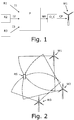
- Fig. 2 shows a sketch for illustrating three wind turbines W1, W2, W3 each with RF receivers, e.g. located in their nacelles, and an RF source RS, e.g. a mobile phone, transmitting RF signals.
- RF receivers e.g. located in their nacelles
- RF source RS e.g. a mobile phone
- the proposed method is not limited to any particular radio communication standard, but the primary radio source would likely be personal mobile telecommunication equipment. As such, the behavior of popular standards such as, 2G (GSM), 3G (UMTS, CDMA2000), 4G (LTE Advanced), etc. are discussed in this section.
- the method is preferably adapted for detecting personal mobile telecommunication communicating also according to future, not yet known, standards. E.g. this may be implemented in software, in case SDR receivers are used as RF receivers.
- Mobile phones, or terminals have a high degree of focus on energy efficiency because they are driven from a battery. As such, the standards they employ have been designed to have the terminal be passive and only transmit radio signals when necessary. The terminals would then become active during a call, during transmission of a text message, or during an active data transmission.
- the terminals are required to communicate with the base stations in the cell phone network, so that the network is aware that the terminal is ready, and that it is connected to a given radio tower. This occurs both during movement, when a terminal switches to another tower, and periodically with what is known as location updates. Location updates are set at some fixed period, typically 1 to multiple hours. So a terminal which is on will be periodically active, even when completely idle and not in use by its user.
- Modern phones are rarely idle, because a large part of mobile phones today are smart phones. These phones have multiple application making use of the data connection on the network, e.g. Twitter and Facebook, and also have data based methods of communicating, e.g. push notification, voice and video calls over proprietary protocols, IP based text messages, etc. As such, modern phones are typically quite active on the network, and will transmits radio signals quite frequently.
- TDOA uses the difference in arrival time to infer where the signal could have originated. It amounts to finding the intersection between hyperboloids, and it can be done by solving the following system. Let p 1 , p 2 , ..., p k be the position of k radio receivers defined by x k ,y k ,z k , and e be the unknown position, x e ,y e z e , of an emitter.
- the first equation is the distance (squared) between position n and the emitter
- the measured time difference must be done very precisely.
- the signal In order to localize a radio signal, the signal should be separated from other signals using the same medium.
- the techniques used for coordinating this is known as the channel access method, and examples include separation in time (TDMA) or frequency (FDMA).
- the detection method should take this into account when trying to localize the signal.
- the communication may employ TDMA, CDMA, or FDMA or a combination.
- Control channels are used e.g. for joining or leaving a base station and for initiating and terminating calls and for other types of bursty traffic such as SMS (short messaging services).
- voice/traffic channels are used for communication after the setup mentioned before, and typically employ some dedicated resource (e.g. frequency) in the network
- the acquisition of the signals may follow a method similar to one described e.g. in US 5,327,144 .
- a minimum received power should also be selected, ie. a threshold for when the location detection algorithm is proceeded with, or the sample discarded.
- the frames would then be cross-correlated in order to detect the differences in time of arrival. This is a well known technique and would result in a set of estimated time differences which can be used in the above TDOA equations.
- radio sources Once radio sources have been localized, they should be classified in order to identify their possibly source, and whether to include them in the consideration of the noise operating mode.
- Fig. 3 shows a flow diagram including possible elements to be part of a classification algorithm.
- the output from the radio source localization step is a series of observations (x, y, z, t, f), i.e. coordinates, time stamps, and the base frequency of the observation. These can be grouped in order to identify which observations belong to the same radio receiver.
- the first step would be to identify the spectrum based on the base frequency of the observation.
- the observations would be assigned a signal type, e.g. mobile phone, the rationale being that a mobile phone would never send information of another type.
- the types would be based on spectrum regulations by relevant agencies, such as the ITU.
- the observations would be grouped by time and location. Ie. one would select a threshold ⁇ t in time and distance ⁇ d, and two observations ( x 1 , y 1 , z 1 , t 1 , f 1 ) and ( x 2 , y 2 , z 2 , t 2 , f 2 ) would then be assumed to be from the same source if x 2 ⁇ x 1 2 + y 2 ⁇ y 1 2 + z 2 ⁇ z 1 2 ⁇ ⁇ d and t 2 ⁇ t 1 ⁇ ⁇ t i.e. if they are close in space and time. Observations grouped in this fashion would then be assumed to come from the same radio source.
- the observations may also be grouped by their height, i.e. observations above a certain height may be assumed to be originating from machinery, such as a drone, and excluded from noise mode considerations.
- An additional grouping that could be done, is to group observations very close to each other (few meters) for long periods of time (several hours). These observations could be from fixed deployments of GSM/UMTS equipment, e.g. bus stops, or from the GSM/UMTS equipment in a car. Once identified these observations could be excluded from noise mode consideration.
- the observations from mobile telephony equipment could be subject to an estimation of their velocity. This would be based on the grouping in the previous step, and you would arrange the grouped observations by time, and estimate their velocity by calculating their distance and dividing by time, resulting in a series of estimates velocities. These velocities could be further averaged, in an effort to denoise them, and to provide a more robust estimate. More advanced algorithms such as Kalman filtering could also be applied to the observations. The observations would then be classified:
- Radio sources in the walking or running category could be included in consideration for the noise mode. The others could be excluded, the rationale being that if you are driving or in a helicopter, the ambient noise would exceed the noise requirements of the wind turbine.
- the radio sources could be further classified by including GIS information. Examples include zoning of the area around the wind turbine park (residential, agriculture, roads, industry). Observation in certain zones, e.g. roads, could be excluded from consideration, and the zone could also be used in determining the amount of observations needed to affect the noise mode, and the weight of the effect. E.g. observations in a residential zone would be weighted higher than observations in an industrial zone. This matches the different noise regulations in certain countries, for instance in Germany.
- the impact on the selected noise mode of operation is preferably assessed.
- Fig. 4 shows a wind turbine W1 where its surrounding area is grouped into noise zones Z1, Z2, Z3, i.e. zones where different levels of noise mode changes are required to maintain acceptable noise levels.
- an RF source RS is located in zone three Z3.
- the area of the zones Z1, Z2, Z3 could depend on the turbine type, and the particular site at which it is installed. For instance, noise may be dampened by terrain, and is also dependent on wind direction.
- the noise zones Z1, Z2, Z3 could either be measured as part of the planning and installation phase of the wind turbine, or they could be estimated by calculating them according to ISO 9613-2. These zones may also be wind direction dependent, and change according to the currently observed wind direction.
- Noise mode of operation could then be adjusted according to different schemes, e.g. as follows:
- the advantage of the dynamic method is that it is conservative with respect to noise, but it can also affect turbine operations in a way that is hard to predict.
- the daily profile would be more predictable, but have the risk that high noise levels can be experienced for people near the turbine at unusual hours.
- Figs. 5 and 6 show how the control system is preferably deployed of the equipment in a wind turbine park.
- RF receivers RFR are installed in a subset of wind turbines WT, i.e. in at least three, but preferably in more of the wind turbines WT.
- a data storage and operating module either on dedicated hardware or hardware shared with the turbine controller, for the RF receivers RFR. This would be connected to the internal network in the park.
- the RF receivers RFR would be precisely geolocated, e.g. with GPS/Glonass/Galileo equipment, and the position of the RF receivers RFR would be recorded and stored in the turbine operating module.
- the turbine operating module could also include one of the following methods for time synchronization between the turbine operating modules:
- the park operating module could include the overall configuration of the system, and coordinate the operation of the system.
- Fig. 7 shows steps of a method embodiment for controlling a noise mode of operation of a wind turbine in a wind turbine park.
- First receiving inputs R_RF_I from a plurality of RF receivers located at positions in respective wind turbines in the wind turbine park.
- controlling C_NM the noise mode of operation of one or more wind turbines in the wind turbine park according to the measure indicative of a location of the RF source.
Landscapes
- Engineering & Computer Science (AREA)
- Mechanical Engineering (AREA)
- Sustainable Development (AREA)
- Sustainable Energy (AREA)
- Chemical & Material Sciences (AREA)
- Combustion & Propulsion (AREA)
- Life Sciences & Earth Sciences (AREA)
- General Engineering & Computer Science (AREA)
- Computer Networks & Wireless Communication (AREA)
- Signal Processing (AREA)
- Physics & Mathematics (AREA)
- Fluid Mechanics (AREA)
- Wind Motors (AREA)
Claims (15)
- Steuersystem zum Steuern eines Betriebs-Schallmodus (Noise Mode - NM) einer Windkraftanlage (W1) in einem Windkraftanlagenpark, wobei das Steuersystem einen Prozessor (P) umfasst und eingerichtet ist, um:- Eingaben (I1, I2, I3) aus einer Vielzahl von Hochfrequenzempfängern (R1, R2, R3) zu empfangen, die an Positionen in oder nahe jeweiliger Windkraftanlagen in dem Windkraftanlagenpark liegen,- ein Maß zu berechnen, das eine Lage einer Hochfrequenzquelle (RS) nahe einer Windkraftanlage (W1) des Windkraftanlagenparks als Reaktion auf die Eingaben (I1, I2, I3) aus der Vielzahl von Hochfrequenzempfängern (R1, R2, R3) angibt, und- den Betriebs-Schallmodus (NM) einer oder mehrerer Windkraftanlagen (W1) in dem Windkraftanlagenpark gemäß dem Maß, das eine Lage einer Hochfrequenzquelle (RS) angibt, zu steuern.
- Steuersystem nach Anspruch 1, das eingerichtet ist, um ein Maß zu berechnen, das eine Lage einer Vielzahl einzelner Hochfrequenzquellen (RS) innerhalb einer vordefinierten Fläche (Z1, Z2, Z3) um mindestens eine Windkraftanlage (W1) des Windkraftanlagenparks als Reaktion auf die Eingaben (I1, I2, I3) aus der Vielzahl von Hochfrequenzempfängern (R1, R2, R3) angibt.
- Steuersystem nach einem der vorstehenden Ansprüche, das eingerichtet ist, um eine Lage einer Hochfrequenzquelle (RS) durch Ausführen einer Multilaterationsberechnung als Reaktion auf Eingaben (I1, I2, I3) aus mindestens drei Hochfrequenzempfängern (R1, R2, R3) zu bestimmen.
- Steuersystem nach einem der vorstehenden Ansprüche, das eingerichtet ist, um eine Quellenklassifizierung einer einzelnen Hochfrequenzquelle (RS) auszuführen.
- Steuersystem nach einem der vorstehenden Ansprüche, das eingerichtet ist, um individuell den Betriebs-Schallmodus (NM) einer Vielzahl von Windkraftanlagen (W1, W2, W3) in dem Windkraftanlagenpark als Reaktion auf das Maß, das eine Lage einer Hochfrequenzquelle (RS) angibt, zu steuern.
- Steuersystem nach einem der vorstehenden Ansprüche, wobei der Betriebs-Schallmodus (NM) der einen oder mehreren Windkraftanlagen (W1, W2, W3) durch Auswählen zwischen einer Anzahl vordefinierter Betriebs-Schallmodi als Reaktion auf das Maß, das eine Lage einer Hochfrequenzquelle (RS) angibt, gesteuert wird.
- Steuersystem nach einem der vorstehenden Ansprüche, wobei das Steuern des Betriebs-Schallmodus einer oder mehrerer Windkraftanlagen (W1, W2, W3) das Steuern mindestens des Blattwinkels umfasst.
- Steuersystem nach einem der vorstehenden Ansprüche, wobei das Berechnen eines Maßes, das eine Lage einer Hochfrequenzquelle (RS) angibt, innerhalb eines begrenzten vordefinierten Hochfrequenzbands ausgeführt wird, das mindestens eines der Folgenden umfasst: das GSM-Band, das UMTS, das DCMA2000-Band und das LTE-Band.
- Steuersystem nach einem der vorstehenden Ansprüche, das mindestens teilweise auf einem Windparkserver (WPS) umgesetzt wird, der eingerichtet ist, um den Windkraftanlagenpark zu steuern, wobei der Windparkserver (WPS) mit mindestens drei und Hochfrequenzempfängern (RFR) über ein verdrahtetes oder drahtloses Netzwerk verbunden ist, um Zeitsynchronisation eines Hochfrequenzsignals, das aus einer Quellenlage über die mindestens drei Hochfrequenzempfänger (RFR) empfangen wird, zu erlauben.
- Steuersystem nach einem der vorstehenden Ansprüche, das eingerichtet ist, um das Maß, das eine Lage einer Hochfrequenzquelle (RS) angibt, kontinuierlich zu aktualisieren und den Betriebs-Schallmodus (NM) mindestens einer der Windkraftanlagen (W1) des Windkraftanlagenparks entsprechend anzupassen.
- Steuersystem nach einem der vorstehenden Ansprüche, das eingerichtet ist, um Eingaben (I1, I2, I3) aus der Vielzahl von Hochfrequenzempfängern (R1, R2, R3) zu empfangen, um Maße zu berechnen, die die Lagen von Hochfrequenzquellen (RS) über eine Zeitspanne angeben, um ein statistisches Maß als Reaktion auf die Maße zu berechnen, die Lagen von Hochfrequenzquellen über eine Zeitspanne angeben, und den Betriebs-Schallmodus (NM) einer oder mehrerer Windkraftanlagen (W1) in dem Windkraftanlagenpark gemäß der statistischen Messung zu steuern.
- Steuersystem nach Anspruch 11, das eingerichtet ist,- um die statistischen Messdaten über eine Periode einer Vielzahl von Tagen zu berechnen,- um einen unterschiedlichen ersten und zweiten Betriebs-Schallmodus entsprechend zu bestimmen, und- um die Betriebs-Schallmodi (NM) mindestens einer Windkraftanlage (W1) des Windkraftanlagenparks als Reaktion auf die Tageszeit- und Nachtzeit-Betriebs-Schallmodi zu steuern.
- Windkraftanlagenpark, der umfasst:- mindestens eine Windkraftanlage (W1),- eine Vielzahl von Hochfrequenzempfängern (R1, R2, R3), und- ein Steuersystem nach einem der Ansprüche 1 bis 12 zum Steuern eines Betriebs-Schallmodus (NM) der mindestens einen Windkraftanlage (W1) in dem Windkraftanlagenpark.
- Verfahren zum Steuern eines Betriebs-Schallmodus einer Windkraftanlage in einem Windkraftanlagenpark, wobei das Verfahren umfasst:- Empfangen von Eingaben (R_RF_I) aus einer Vielzahl von Hochfrequenzempfängern, die an Positionen in oder nahe jeweiliger Windkraftanlagen in dem Windkraftanlagenpark liegen,- Berechnen (C_LC) eines Maßes, das eine Lage einer Hochfrequenzquelle nahe einer Windkraftanlage des Windkraftanlagenparks als Reaktion auf die Eingaben aus der Vielzahl von Hochfrequenzempfängern angibt, und- Steuern (C_NM) des Betriebs-Schallmodus (NM) einer oder mehrerer Windkraftanlagen in dem Windkraftanlagenpark gemäß dem Maß, das eine Lage einer Hochfrequenzquelle angibt.
- Computerprogrammprodukt, das Anweisungen aufweist, die, wenn sie ausgeführt werden, ein Rechengerät oder ein Rechensystem, das einen Prozessor umfasst, veranlassen, ein Verfahren nach Anspruch 14 auszuführen.
Applications Claiming Priority (2)
| Application Number | Priority Date | Filing Date | Title |
|---|---|---|---|
| DKPA201670979 | 2016-12-09 | ||
| PCT/DK2017/050391 WO2018103801A1 (en) | 2016-12-09 | 2017-11-24 | Adaptive noise control for wind turbine |
Publications (2)
| Publication Number | Publication Date |
|---|---|
| EP3551879A1 EP3551879A1 (de) | 2019-10-16 |
| EP3551879B1 true EP3551879B1 (de) | 2020-10-28 |
Family
ID=60515070
Family Applications (1)
| Application Number | Title | Priority Date | Filing Date |
|---|---|---|---|
| EP17807697.2A Active EP3551879B1 (de) | 2016-12-09 | 2017-11-24 | Adaptive geräuschkontrolle für windturbine |
Country Status (3)
| Country | Link |
|---|---|
| US (1) | US11220997B2 (de) |
| EP (1) | EP3551879B1 (de) |
| WO (1) | WO2018103801A1 (de) |
Families Citing this family (4)
| Publication number | Priority date | Publication date | Assignee | Title |
|---|---|---|---|---|
| EP3551879B1 (de) | 2016-12-09 | 2020-10-28 | Vestas Wind Systems A/S | Adaptive geräuschkontrolle für windturbine |
| EP3672010A1 (de) * | 2018-12-19 | 2020-06-24 | Siemens Gamesa Renewable Energy A/S | Bewohnerbeteiligung an der steuerung eines windparks |
| ES2991956T3 (es) * | 2020-10-27 | 2024-12-05 | Vestas Wind Sys As | Reducción de emisiones de ruido de una turbina eólica |
| EP4431726A1 (de) * | 2023-03-17 | 2024-09-18 | Siemens Gamesa Renewable Energy A/S | Bewertung der geräuschemission für eine windparkumgebung |
Family Cites Families (14)
| Publication number | Priority date | Publication date | Assignee | Title |
|---|---|---|---|---|
| US9392406B2 (en) | 2005-02-03 | 2016-07-12 | Trueposition, Inc. | Method and system for location-based monitoring of a mobile device |
| US20070031237A1 (en) * | 2005-07-29 | 2007-02-08 | General Electric Company | Method and apparatus for producing wind energy with reduced wind turbine noise |
| US8457798B2 (en) * | 2006-03-14 | 2013-06-04 | Jamie Hackett | Long-range radio frequency receiver-controller module and wireless control system comprising same |
| US20080271123A1 (en) * | 2007-04-30 | 2008-10-30 | General Instrument Corporation | System and Method For Controlling Devices in a Home-Automation Network |
| US20100135798A1 (en) | 2009-02-10 | 2010-06-03 | General Electric Company | Wind turbine noise controls |
| US7896613B2 (en) * | 2009-06-03 | 2011-03-01 | General Electric Company | System and method for wind turbine noise control and damage detection |
| US20140248148A1 (en) * | 2011-04-28 | 2014-09-04 | Vestas Wind Systems A/S | Wind turbine noise control methods |
| US8304926B2 (en) * | 2011-09-16 | 2012-11-06 | General Electric Company | Wind turbine sound management |
| US9622028B2 (en) | 2011-09-26 | 2017-04-11 | Telefonaktiebolaget L M Ericsson | Methods and arrangements for high accuracy positioning |
| US9014861B2 (en) * | 2011-12-20 | 2015-04-21 | General Electric Company | Method and system for noise-controlled operation of a wind turbine |
| US20140135998A1 (en) * | 2013-09-16 | 2014-05-15 | Zhiheng Cao | Method and Apparatus for Energy Efficient Heating and Air Conditioning Automation |
| US9696701B2 (en) * | 2013-12-07 | 2017-07-04 | Svv Technology Innovations, Inc. | Radio frequency occupancy sensing load control |
| US10024304B2 (en) * | 2015-05-21 | 2018-07-17 | General Electric Company | System and methods for controlling noise propagation of wind turbines |
| EP3551879B1 (de) | 2016-12-09 | 2020-10-28 | Vestas Wind Systems A/S | Adaptive geräuschkontrolle für windturbine |
-
2017
- 2017-11-24 EP EP17807697.2A patent/EP3551879B1/de active Active
- 2017-11-24 WO PCT/DK2017/050391 patent/WO2018103801A1/en not_active Ceased
- 2017-11-24 US US16/468,192 patent/US11220997B2/en active Active
Non-Patent Citations (1)
| Title |
|---|
| None * |
Also Published As
| Publication number | Publication date |
|---|---|
| US11220997B2 (en) | 2022-01-11 |
| WO2018103801A1 (en) | 2018-06-14 |
| EP3551879A1 (de) | 2019-10-16 |
| US20190331093A1 (en) | 2019-10-31 |
Similar Documents
| Publication | Publication Date | Title |
|---|---|---|
| EP3551879B1 (de) | Adaptive geräuschkontrolle für windturbine | |
| US9743253B2 (en) | Method and arrangement for locating a mobile device | |
| US20250097811A1 (en) | Systems and methods for reducing system information acquisition during cell reselection in a non-terrestrial network | |
| JP2025528095A (ja) | ワイヤレス通信ネットワークにおける機械学習測位モデルのトレーニング | |
| US8509810B2 (en) | Method and apparatus for geo-locating mobile station | |
| US8526961B2 (en) | Method and apparatus for mapping operating parameter in coverage area of wireless network | |
| EP2805189B1 (de) | Verwendung von blitzdaten zur erzeugung von proxy-reflektivitätsdaten | |
| WO2011100859A8 (en) | Improvements on otdoa and agnss positioning and timing information obtaining and updating | |
| EP2773973A1 (de) | Positionierung von benutzergeräten auf der basis von virtuellen referenzmessungen | |
| CN105745894B (zh) | 通信方法、装置及系统 | |
| KR20230173117A (ko) | 모바일 앵커를 포함하는 지리적으로 유사한 앵커들을 사용한 포지셔닝 | |
| AU2023274190A1 (en) | Method and apparatus for reducing energy consumption | |
| EP4413772A1 (de) | Minimierung von fahrtests für nicht-terrestrische netzwerke | |
| WO2011058102A3 (en) | Gps automated tracking of mobile monitoring units | |
| KR20230062563A (ko) | 포지셔닝을 위한 선택적 심볼 측정 | |
| Luo et al. | Delay evaluation for cellular-connected drones: Experiments and analysis | |
| WO2024186246A1 (en) | Methods for configuring and using sensing target information | |
| US11962654B2 (en) | Communication system, communication method, communication apparatus, and computer program product | |
| US12051438B1 (en) | Using machine learning to locate mobile device | |
| EP2657916A2 (de) | Anzeige eines Auto-Managers für Mobilien | |
| CN112911516A (zh) | 无线基地台行进轨迹生成方法及系统 | |
| CN121442288A (zh) | 一种通信感知一体化的实现方法和电子设备 | |
| CN106792530A (zh) | 一种目标伪基站的定位方法及系统 | |
| WO2025144093A1 (en) | Methods and apparatuses for sensing in a communication network | |
| WO2025144092A1 (en) | Methods and apparatuses for sensing in a communication network |
Legal Events
| Date | Code | Title | Description |
|---|---|---|---|
| STAA | Information on the status of an ep patent application or granted ep patent |
Free format text: STATUS: UNKNOWN |
|
| STAA | Information on the status of an ep patent application or granted ep patent |
Free format text: STATUS: THE INTERNATIONAL PUBLICATION HAS BEEN MADE |
|
| PUAI | Public reference made under article 153(3) epc to a published international application that has entered the european phase |
Free format text: ORIGINAL CODE: 0009012 |
|
| STAA | Information on the status of an ep patent application or granted ep patent |
Free format text: STATUS: REQUEST FOR EXAMINATION WAS MADE |
|
| 17P | Request for examination filed |
Effective date: 20190619 |
|
| AK | Designated contracting states |
Kind code of ref document: A1 Designated state(s): AL AT BE BG CH CY CZ DE DK EE ES FI FR GB GR HR HU IE IS IT LI LT LU LV MC MK MT NL NO PL PT RO RS SE SI SK SM TR |
|
| GRAP | Despatch of communication of intention to grant a patent |
Free format text: ORIGINAL CODE: EPIDOSNIGR1 |
|
| STAA | Information on the status of an ep patent application or granted ep patent |
Free format text: STATUS: GRANT OF PATENT IS INTENDED |
|
| INTG | Intention to grant announced |
Effective date: 20200625 |
|
| GRAS | Grant fee paid |
Free format text: ORIGINAL CODE: EPIDOSNIGR3 |
|
| GRAA | (expected) grant |
Free format text: ORIGINAL CODE: 0009210 |
|
| STAA | Information on the status of an ep patent application or granted ep patent |
Free format text: STATUS: THE PATENT HAS BEEN GRANTED |
|
| AK | Designated contracting states |
Kind code of ref document: B1 Designated state(s): AL AT BE BG CH CY CZ DE DK EE ES FI FR GB GR HR HU IE IS IT LI LT LU LV MC MK MT NL NO PL PT RO RS SE SI SK SM TR |
|
| REG | Reference to a national code |
Ref country code: GB Ref legal event code: FG4D |
|
| REG | Reference to a national code |
Ref country code: CH Ref legal event code: EP |
|
| REG | Reference to a national code |
Ref country code: AT Ref legal event code: REF Ref document number: 1328494 Country of ref document: AT Kind code of ref document: T Effective date: 20201115 |
|
| REG | Reference to a national code |
Ref country code: DE Ref legal event code: R096 Ref document number: 602017026500 Country of ref document: DE |
|
| REG | Reference to a national code |
Ref country code: IE Ref legal event code: FG4D |
|
| REG | Reference to a national code |
Ref country code: AT Ref legal event code: MK05 Ref document number: 1328494 Country of ref document: AT Kind code of ref document: T Effective date: 20201028 |
|
| REG | Reference to a national code |
Ref country code: NL Ref legal event code: MP Effective date: 20201028 |
|
| PG25 | Lapsed in a contracting state [announced via postgrant information from national office to epo] |
Ref country code: PT Free format text: LAPSE BECAUSE OF FAILURE TO SUBMIT A TRANSLATION OF THE DESCRIPTION OR TO PAY THE FEE WITHIN THE PRESCRIBED TIME-LIMIT Effective date: 20210301 Ref country code: RS Free format text: LAPSE BECAUSE OF FAILURE TO SUBMIT A TRANSLATION OF THE DESCRIPTION OR TO PAY THE FEE WITHIN THE PRESCRIBED TIME-LIMIT Effective date: 20201028 Ref country code: FI Free format text: LAPSE BECAUSE OF FAILURE TO SUBMIT A TRANSLATION OF THE DESCRIPTION OR TO PAY THE FEE WITHIN THE PRESCRIBED TIME-LIMIT Effective date: 20201028 Ref country code: GR Free format text: LAPSE BECAUSE OF FAILURE TO SUBMIT A TRANSLATION OF THE DESCRIPTION OR TO PAY THE FEE WITHIN THE PRESCRIBED TIME-LIMIT Effective date: 20210129 Ref country code: NO Free format text: LAPSE BECAUSE OF FAILURE TO SUBMIT A TRANSLATION OF THE DESCRIPTION OR TO PAY THE FEE WITHIN THE PRESCRIBED TIME-LIMIT Effective date: 20210128 |
|
| REG | Reference to a national code |
Ref country code: LT Ref legal event code: MG4D |
|
| PG25 | Lapsed in a contracting state [announced via postgrant information from national office to epo] |
Ref country code: SE Free format text: LAPSE BECAUSE OF FAILURE TO SUBMIT A TRANSLATION OF THE DESCRIPTION OR TO PAY THE FEE WITHIN THE PRESCRIBED TIME-LIMIT Effective date: 20201028 Ref country code: PL Free format text: LAPSE BECAUSE OF FAILURE TO SUBMIT A TRANSLATION OF THE DESCRIPTION OR TO PAY THE FEE WITHIN THE PRESCRIBED TIME-LIMIT Effective date: 20201028 Ref country code: LV Free format text: LAPSE BECAUSE OF FAILURE TO SUBMIT A TRANSLATION OF THE DESCRIPTION OR TO PAY THE FEE WITHIN THE PRESCRIBED TIME-LIMIT Effective date: 20201028 Ref country code: IS Free format text: LAPSE BECAUSE OF FAILURE TO SUBMIT A TRANSLATION OF THE DESCRIPTION OR TO PAY THE FEE WITHIN THE PRESCRIBED TIME-LIMIT Effective date: 20210228 Ref country code: BG Free format text: LAPSE BECAUSE OF FAILURE TO SUBMIT A TRANSLATION OF THE DESCRIPTION OR TO PAY THE FEE WITHIN THE PRESCRIBED TIME-LIMIT Effective date: 20210128 Ref country code: ES Free format text: LAPSE BECAUSE OF FAILURE TO SUBMIT A TRANSLATION OF THE DESCRIPTION OR TO PAY THE FEE WITHIN THE PRESCRIBED TIME-LIMIT Effective date: 20201028 Ref country code: AT Free format text: LAPSE BECAUSE OF FAILURE TO SUBMIT A TRANSLATION OF THE DESCRIPTION OR TO PAY THE FEE WITHIN THE PRESCRIBED TIME-LIMIT Effective date: 20201028 |
|
| PG25 | Lapsed in a contracting state [announced via postgrant information from national office to epo] |
Ref country code: HR Free format text: LAPSE BECAUSE OF FAILURE TO SUBMIT A TRANSLATION OF THE DESCRIPTION OR TO PAY THE FEE WITHIN THE PRESCRIBED TIME-LIMIT Effective date: 20201028 Ref country code: NL Free format text: LAPSE BECAUSE OF FAILURE TO SUBMIT A TRANSLATION OF THE DESCRIPTION OR TO PAY THE FEE WITHIN THE PRESCRIBED TIME-LIMIT Effective date: 20201028 |
|
| REG | Reference to a national code |
Ref country code: CH Ref legal event code: PL |
|
| REG | Reference to a national code |
Ref country code: DE Ref legal event code: R097 Ref document number: 602017026500 Country of ref document: DE |
|
| PG25 | Lapsed in a contracting state [announced via postgrant information from national office to epo] |
Ref country code: CZ Free format text: LAPSE BECAUSE OF FAILURE TO SUBMIT A TRANSLATION OF THE DESCRIPTION OR TO PAY THE FEE WITHIN THE PRESCRIBED TIME-LIMIT Effective date: 20201028 Ref country code: EE Free format text: LAPSE BECAUSE OF FAILURE TO SUBMIT A TRANSLATION OF THE DESCRIPTION OR TO PAY THE FEE WITHIN THE PRESCRIBED TIME-LIMIT Effective date: 20201028 Ref country code: LU Free format text: LAPSE BECAUSE OF NON-PAYMENT OF DUE FEES Effective date: 20201124 Ref country code: MC Free format text: LAPSE BECAUSE OF FAILURE TO SUBMIT A TRANSLATION OF THE DESCRIPTION OR TO PAY THE FEE WITHIN THE PRESCRIBED TIME-LIMIT Effective date: 20201028 Ref country code: LT Free format text: LAPSE BECAUSE OF FAILURE TO SUBMIT A TRANSLATION OF THE DESCRIPTION OR TO PAY THE FEE WITHIN THE PRESCRIBED TIME-LIMIT Effective date: 20201028 Ref country code: SM Free format text: LAPSE BECAUSE OF FAILURE TO SUBMIT A TRANSLATION OF THE DESCRIPTION OR TO PAY THE FEE WITHIN THE PRESCRIBED TIME-LIMIT Effective date: 20201028 Ref country code: SK Free format text: LAPSE BECAUSE OF FAILURE TO SUBMIT A TRANSLATION OF THE DESCRIPTION OR TO PAY THE FEE WITHIN THE PRESCRIBED TIME-LIMIT Effective date: 20201028 Ref country code: RO Free format text: LAPSE BECAUSE OF FAILURE TO SUBMIT A TRANSLATION OF THE DESCRIPTION OR TO PAY THE FEE WITHIN THE PRESCRIBED TIME-LIMIT Effective date: 20201028 |
|
| REG | Reference to a national code |
Ref country code: BE Ref legal event code: MM Effective date: 20201130 |
|
| PG25 | Lapsed in a contracting state [announced via postgrant information from national office to epo] |
Ref country code: DK Free format text: LAPSE BECAUSE OF FAILURE TO SUBMIT A TRANSLATION OF THE DESCRIPTION OR TO PAY THE FEE WITHIN THE PRESCRIBED TIME-LIMIT Effective date: 20201028 Ref country code: LI Free format text: LAPSE BECAUSE OF NON-PAYMENT OF DUE FEES Effective date: 20201130 Ref country code: CH Free format text: LAPSE BECAUSE OF NON-PAYMENT OF DUE FEES Effective date: 20201130 |
|
| PLBE | No opposition filed within time limit |
Free format text: ORIGINAL CODE: 0009261 |
|
| STAA | Information on the status of an ep patent application or granted ep patent |
Free format text: STATUS: NO OPPOSITION FILED WITHIN TIME LIMIT |
|
| 26N | No opposition filed |
Effective date: 20210729 |
|
| PG25 | Lapsed in a contracting state [announced via postgrant information from national office to epo] |
Ref country code: AL Free format text: LAPSE BECAUSE OF FAILURE TO SUBMIT A TRANSLATION OF THE DESCRIPTION OR TO PAY THE FEE WITHIN THE PRESCRIBED TIME-LIMIT Effective date: 20201028 Ref country code: IE Free format text: LAPSE BECAUSE OF NON-PAYMENT OF DUE FEES Effective date: 20201124 Ref country code: IT Free format text: LAPSE BECAUSE OF FAILURE TO SUBMIT A TRANSLATION OF THE DESCRIPTION OR TO PAY THE FEE WITHIN THE PRESCRIBED TIME-LIMIT Effective date: 20201028 |
|
| PG25 | Lapsed in a contracting state [announced via postgrant information from national office to epo] |
Ref country code: SI Free format text: LAPSE BECAUSE OF FAILURE TO SUBMIT A TRANSLATION OF THE DESCRIPTION OR TO PAY THE FEE WITHIN THE PRESCRIBED TIME-LIMIT Effective date: 20201028 |
|
| PG25 | Lapsed in a contracting state [announced via postgrant information from national office to epo] |
Ref country code: IS Free format text: LAPSE BECAUSE OF FAILURE TO SUBMIT A TRANSLATION OF THE DESCRIPTION OR TO PAY THE FEE WITHIN THE PRESCRIBED TIME-LIMIT Effective date: 20210228 Ref country code: TR Free format text: LAPSE BECAUSE OF FAILURE TO SUBMIT A TRANSLATION OF THE DESCRIPTION OR TO PAY THE FEE WITHIN THE PRESCRIBED TIME-LIMIT Effective date: 20201028 Ref country code: MT Free format text: LAPSE BECAUSE OF FAILURE TO SUBMIT A TRANSLATION OF THE DESCRIPTION OR TO PAY THE FEE WITHIN THE PRESCRIBED TIME-LIMIT Effective date: 20201028 Ref country code: CY Free format text: LAPSE BECAUSE OF FAILURE TO SUBMIT A TRANSLATION OF THE DESCRIPTION OR TO PAY THE FEE WITHIN THE PRESCRIBED TIME-LIMIT Effective date: 20201028 |
|
| PG25 | Lapsed in a contracting state [announced via postgrant information from national office to epo] |
Ref country code: MK Free format text: LAPSE BECAUSE OF FAILURE TO SUBMIT A TRANSLATION OF THE DESCRIPTION OR TO PAY THE FEE WITHIN THE PRESCRIBED TIME-LIMIT Effective date: 20201028 |
|
| PG25 | Lapsed in a contracting state [announced via postgrant information from national office to epo] |
Ref country code: BE Free format text: LAPSE BECAUSE OF NON-PAYMENT OF DUE FEES Effective date: 20201130 |
|
| P01 | Opt-out of the competence of the unified patent court (upc) registered |
Effective date: 20230521 |
|
| PGFP | Annual fee paid to national office [announced via postgrant information from national office to epo] |
Ref country code: DE Payment date: 20251126 Year of fee payment: 9 |
|
| PGFP | Annual fee paid to national office [announced via postgrant information from national office to epo] |
Ref country code: GB Payment date: 20251125 Year of fee payment: 9 |
|
| PGFP | Annual fee paid to national office [announced via postgrant information from national office to epo] |
Ref country code: FR Payment date: 20251124 Year of fee payment: 9 |