EP3551349B1 - Transducteurs de mode plans dans le sens de l'épaisseur et dispositifs associés - Google Patents
Transducteurs de mode plans dans le sens de l'épaisseur et dispositifs associés Download PDFInfo
- Publication number
- EP3551349B1 EP3551349B1 EP17818409.9A EP17818409A EP3551349B1 EP 3551349 B1 EP3551349 B1 EP 3551349B1 EP 17818409 A EP17818409 A EP 17818409A EP 3551349 B1 EP3551349 B1 EP 3551349B1
- Authority
- EP
- European Patent Office
- Prior art keywords
- transducer
- flexible support
- electrically conductive
- conductive flexible
- piezoelectric block
- Prior art date
- Legal status (The legal status is an assumption and is not a legal conclusion. Google has not performed a legal analysis and makes no representation as to the accuracy of the status listed.)
- Active
Links
Images


Classifications
-
- B—PERFORMING OPERATIONS; TRANSPORTING
- B06—GENERATING OR TRANSMITTING MECHANICAL VIBRATIONS IN GENERAL
- B06B—METHODS OR APPARATUS FOR GENERATING OR TRANSMITTING MECHANICAL VIBRATIONS OF INFRASONIC, SONIC, OR ULTRASONIC FREQUENCY, e.g. FOR PERFORMING MECHANICAL WORK IN GENERAL
- B06B1/00—Methods or apparatus for generating mechanical vibrations of infrasonic, sonic, or ultrasonic frequency
- B06B1/02—Methods or apparatus for generating mechanical vibrations of infrasonic, sonic, or ultrasonic frequency making use of electrical energy
- B06B1/06—Methods or apparatus for generating mechanical vibrations of infrasonic, sonic, or ultrasonic frequency making use of electrical energy operating with piezoelectric effect or with electrostriction
- B06B1/0644—Methods or apparatus for generating mechanical vibrations of infrasonic, sonic, or ultrasonic frequency making use of electrical energy operating with piezoelectric effect or with electrostriction using a single piezoelectric element
- B06B1/0662—Methods or apparatus for generating mechanical vibrations of infrasonic, sonic, or ultrasonic frequency making use of electrical energy operating with piezoelectric effect or with electrostriction using a single piezoelectric element with an electrode on the sensitive surface
- B06B1/067—Methods or apparatus for generating mechanical vibrations of infrasonic, sonic, or ultrasonic frequency making use of electrical energy operating with piezoelectric effect or with electrostriction using a single piezoelectric element with an electrode on the sensitive surface which is used as, or combined with, an impedance matching layer
-
- B—PERFORMING OPERATIONS; TRANSPORTING
- B06—GENERATING OR TRANSMITTING MECHANICAL VIBRATIONS IN GENERAL
- B06B—METHODS OR APPARATUS FOR GENERATING OR TRANSMITTING MECHANICAL VIBRATIONS OF INFRASONIC, SONIC, OR ULTRASONIC FREQUENCY, e.g. FOR PERFORMING MECHANICAL WORK IN GENERAL
- B06B1/00—Methods or apparatus for generating mechanical vibrations of infrasonic, sonic, or ultrasonic frequency
- B06B1/02—Methods or apparatus for generating mechanical vibrations of infrasonic, sonic, or ultrasonic frequency making use of electrical energy
- B06B1/06—Methods or apparatus for generating mechanical vibrations of infrasonic, sonic, or ultrasonic frequency making use of electrical energy operating with piezoelectric effect or with electrostriction
- B06B1/0644—Methods or apparatus for generating mechanical vibrations of infrasonic, sonic, or ultrasonic frequency making use of electrical energy operating with piezoelectric effect or with electrostriction using a single piezoelectric element
-
- G—PHYSICS
- G01—MEASURING; TESTING
- G01F—MEASURING VOLUME, VOLUME FLOW, MASS FLOW OR LIQUID LEVEL; METERING BY VOLUME
- G01F1/00—Measuring the volume flow or mass flow of fluid or fluent solid material wherein the fluid passes through a meter in a continuous flow
- G01F1/66—Measuring the volume flow or mass flow of fluid or fluent solid material wherein the fluid passes through a meter in a continuous flow by measuring frequency, phase shift or propagation time of electromagnetic or other waves, e.g. using ultrasonic flowmeters
- G01F1/662—Constructional details
-
- G—PHYSICS
- G01—MEASURING; TESTING
- G01F—MEASURING VOLUME, VOLUME FLOW, MASS FLOW OR LIQUID LEVEL; METERING BY VOLUME
- G01F1/00—Measuring the volume flow or mass flow of fluid or fluent solid material wherein the fluid passes through a meter in a continuous flow
- G01F1/66—Measuring the volume flow or mass flow of fluid or fluent solid material wherein the fluid passes through a meter in a continuous flow by measuring frequency, phase shift or propagation time of electromagnetic or other waves, e.g. using ultrasonic flowmeters
- G01F1/667—Arrangements of transducers for ultrasonic flowmeters; Circuits for operating ultrasonic flowmeters
-
- G—PHYSICS
- G01—MEASURING; TESTING
- G01H—MEASUREMENT OF MECHANICAL VIBRATIONS OR ULTRASONIC, SONIC OR INFRASONIC WAVES
- G01H11/00—Measuring mechanical vibrations or ultrasonic, sonic or infrasonic waves by detecting changes in electric or magnetic properties
- G01H11/06—Measuring mechanical vibrations or ultrasonic, sonic or infrasonic waves by detecting changes in electric or magnetic properties by electric means
- G01H11/08—Measuring mechanical vibrations or ultrasonic, sonic or infrasonic waves by detecting changes in electric or magnetic properties by electric means using piezoelectric devices
-
- G—PHYSICS
- G01—MEASURING; TESTING
- G01N—INVESTIGATING OR ANALYSING MATERIALS BY DETERMINING THEIR CHEMICAL OR PHYSICAL PROPERTIES
- G01N29/00—Investigating or analysing materials by the use of ultrasonic, sonic or infrasonic waves; Visualisation of the interior of objects by transmitting ultrasonic or sonic waves through the object
- G01N29/02—Analysing fluids
- G01N29/024—Analysing fluids by measuring propagation velocity or propagation time of acoustic waves
-
- G—PHYSICS
- G01—MEASURING; TESTING
- G01N—INVESTIGATING OR ANALYSING MATERIALS BY DETERMINING THEIR CHEMICAL OR PHYSICAL PROPERTIES
- G01N2291/00—Indexing codes associated with group G01N29/00
- G01N2291/02—Indexing codes associated with the analysed material
- G01N2291/028—Material parameters
- G01N2291/02836—Flow rate, liquid level
-
- H—ELECTRICITY
- H10—SEMICONDUCTOR DEVICES; ELECTRIC SOLID-STATE DEVICES NOT OTHERWISE PROVIDED FOR
- H10N—ELECTRIC SOLID-STATE DEVICES NOT OTHERWISE PROVIDED FOR
- H10N30/00—Piezoelectric or electrostrictive devices
- H10N30/80—Constructional details
- H10N30/87—Electrodes or interconnections, e.g. leads or terminals
Definitions
- the present inventive concept relates generally to transducers and, more particularly, to ultrasonic transducers and related methods and devices.
- Ultrasonic transducers preferably include small but precisely dimensioned piezoelectric blocks in order to provide a high degree of part-to-part repeatability with low material costs.
- Conventional devices generally include a cylindrical piezoelectric block having a thickness that defines a resonant frequency of the piezoelectric block.
- the element thickness may be, for example, about 7.0 mm when operated at 170 kHz and about 3.0 mm when operated at 400 kHz.
- fabricating precisely dimensioned piezoelectric cylinders of this size and shape can be very expensive as the cylinder faces have to be machined after firing.
- WO-2007/064214 describes an ultrasonic transducer module comprising at least one transmitter layer and at least one receiver layer, each comprising a number of elongated electrodes.
- EP-1237148 describes an ultrasonic transducer comprising a piezoelectric element and an acoustic matching layer.
- US 2015/298174 A1 discloses a transducer comprising a single piezoelectric block with first and second electrically conductive flexible support layer partially on and overhanging the first and second surface of the piezoelectric block.
- the present invention provides a transducer including a single piezoelectric block having first and second opposing surfaces; a first conductive flexible support layer on the first surface of the piezoelectric block, the first flexible support layer having a first thickness; and a second flexible support layer on the second surface of the piezoelectric block, the second flexible support layer having a second thickness, wherein the first and second thicknesses are substantially the same, and wherein the first and second electrically conductive flexible support layers overhang the first and second opposing surfaces of the single piezoelectric block, respectively.
- the first and second thicknesses may be substantially less than a thickness of the piezoelectric block.
- the first and second conductive flexible support layers may include thin metal sheets of material directly on the first and second opposing surfaces of the single piezoelectric block, respectively.
- the thin metal sheets of material may include only stainless steel sheets of material.
- the first and second conductive flexible support layers may be flexible circuits with a copper trace.
- first and second conductive flexible support layers may have a thickness of from about 0.025 mm to about 0.1mm.
- the piezoelectric block may include a soft PZT material selected from one of grade P5A material and P5H material.
- the piezoelectric block may have a thickness of from about 0.5 mm to about 5.0 mm.
- the resonant frequency of the transducer may be about 400 kHz and dimensions of the first and second conductive flexible support layers may be 4.2x4.2x0.1 mm; and dimensions of the piezoelectric block may be 4x4x2 mm.
- first and second conductive flexible support layers may be coupled to the first and second surfaces of the piezoelectric block, respectively, using an adhesive.
- an electrical contact between the piezoelectric block and the first and second conductive flexible support layers may be obtained using the adhesive and without a wire soldered between the piezoelectric block and the first and second conductive flexible support layers.
- the transducer may further include an acoustic matching layer on one of a gas and liquid facing surface of one of the first and second conductive flexible support layers.
- the transducer may be an ultrasonic transducer for use in one of a gas meter and a water meter.
- the present invention further provides a meter including the transducer of claim 1.
- a dicing saw may be used to address the difficult and costly manufacturing of a cylindrical piezoelectric element.
- the dicing saw may be used to create a cuboid piezoelectric element instead of a cylindrical piezoelectric element, which can be a cost-effective way to create a precisely dimensioned part.
- this generally requires a thickness of less than approximately 2.5 mm.
- a thickness mode ultrasonic transducer manufactured using a reduced volume of piezoelectric material to reduce manufacturing costs may be provided as discussed in commonly assigned U.S. Patent Application Serial No. 15/374,044 (Attorney Docket No. 10084-00003).
- the piezoelectric element may be circular, or preferably cuboid to allow precise fabrication using a wafer dicing saw. Additional non-piezoelectric layers or parts may be used to reduce the thickness of piezoelectric material given a target operating frequency and to increase the acoustically transmitting area; however, this may increase the part count and number of adhesive bonding steps, both of which may be undesirable.
- some embodiments of the present inventive concept provide a transducer including a piezoelectric element between electrically conductive flexible support layers, for example, thin flexible shims, which provide mechanical mounting as well as electrical connection.
- the light flexible electrically conducting structures may provide mechanical support and electrical contact to the piezoelectric element and possibly gas or liquid sealing for the transducer as will be discussed further herein with respect to Figs. 1 through 7 .
- a transducer 100 includes a piezoelectric block 121 and first and second conductive flexible support layers 112 and 132, respectively.
- the piezoelectric materials of the piezoelectric block 121 may be, for example, PZT, grades P5A and P5H or substantial equivalents thereof.
- PZT lead zirconate titanate
- the piezoelectric block 121 may have a thickness T6 of from about 0.5 mm to about 5.0 mm. In some embodiments, the piezoelectric block 121 may have a thickness T6 of about 2.0 mm.
- the piezoelectric block may be circular, or it may be cuboid in shape to allow precise fabrication using a wafer dicing saw without departing from the scope of the present inventive concept.
- the conductive flexible support layers 112 and 132 may be any flexible material that has the capability of providing an electrical contact.
- the flexible support layers may be provided by thin metal shims 112 and 132, for example, stainless steel shims, but could be other materials without departing from the scope of the present inventive concept. If metal shims are used, the shims should have a low mass and stiffness relative to the piezoelectric block. Providing stainless steel (metal shims) provides an electrically conductive material to the flexible piezoelectric compound.
- the flexible support layers may be a flexible circuit material with a conductive trace, for example, copper without departing from the scope of the present inventive concept.
- the flexible support layers 112 and 132 may have thicknesses T4 and T5, respectively, of from about 0.025mm to about 0.1 mm.
- the thicknesses T4 and T5 of the flexible support layers may be the same or different. In some embodiments of the present inventive concept, the thicknesses of the flexible support layer 112 and 132 are substantially the same. It should be understood that the thicknesses T4 and T5 of the flexible support layers are very small relative to the thickness of the piezoelectric block 121.
- the flexible support layers should be light and flexible compared to the piezoelectric block to provide mechanical support and electrical connection without greatly influencing the vibrational behavior of the piezoelectric block.
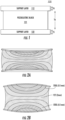
- the 400 kHz thickness-planar mode transducer like Fig. 1 , includes a piezoelectric element having thin metal shims positioned on first and second surfaces of the piezoelectric element.
- the shims provide mechanical mounting and electrical connection.
- the piezoelectric dimensions in the example illustrated in Figs. 2A and 2B are approximately 4X2X2 mm.
- the piezoelectric element has a thickness of about 2.0 mm and the shims have a thickness of about 0.1 mm.
- the transducer experiences compression and in Fig. 2B the transducer experiences expansion.
- Finite element simulations were carried out using Ansys Multiphysics.
- An axisymmetric model was used, containing a piezoelectric centre region enclosed between upper and lower stainless steel sheets (0.1 mm thick).
- the harmonic response was simulated for a 10Vpp drive, with frequency swept from 10 kHz to 1MHz. A 5 percent damping factor was applied.
- Figs. 3 and 4 illustrate contour plots showing results of axisymmetric transducer simulations, plotting axial velocity (m/s) at the center of the transducer.
- Fig. 3 illustrates results when the piezoelectric thickness (y_pzt) is varies and the radius (r_face) of 2.3mm (ref: A).
- Fig. 4 illustrates a varying radius (r_face) and a PZT thickness of 2mm (ref: B).
- the contour plots if Figs. 3 and 4 indicate desirable combinations of operating frequencies and transducer dimensions.
- Fig. 3 illustrates an optimal operating frequency of about 400 kHz when the piezoelectric element thickness, y_pzt, is 2.0 mm.
- FIG. 4 illustrates an optimal operating frequency of approximately 400 kHz when the radius of the front face, r_face, is 2.5 mm.
- the operating frequency varies with both thickness and radius of the transducer, indicating the coupled thickness-planar nature of the resonant mode.
- Fig. 5 the simulated axial velocities of a transducer discussed in U.S. Patent Application Serial No. 15/374,044 (Attorney Docket No. 10084-00003) and the transducer illustrated in Fig. 1 are compared on the graph.
- the simulated axial velocity of the Fig. 1 transducer (lower trace) is slightly lower than the axial velocity of the other transducer (dotted upper trace).
- the velocity of the Fig. 1 transducer is slightly lower, this slight loss in velocity may be a small disadvantage compared to the ease of manufacturing of the device of Fig. 1 .
- the flexible support layers are easier to manufacture in the device of Fig. 1 than the front and back blocks of the other transducer.
- a further advantage of embodiments of the present inventive concept is that the flexible support layers provide mechanical mounting, electrical connection and optionally, liquid or gas sealing functions, possibly eliminating the need for additional parts in the transducer assembly.
- some embodiments of the present inventive concept may include an acoustic matching layer 743 on one of a gas and liquid facing surface of one of the first and second conductive flexible support layers.
- the acoustic matching layer 743 is illustrated as being positioned on support layer 712, embodiments of the present inventive concept are not limited to this configuration.
- the acoustic matching layer 743 could be positioned on support layer 732 without departing from the scope of the present inventive concept.
- the acoustic matching layers are used to improve acoustic transmission efficiency between a high acoustic impedance acoustic element (PZT, impedance Z 1 ) and a low acoustic impedance medium (gas, impedance Z 3 ).
- the acoustic impedance of a material is defined as the product of density and speed of sound.
- a matching layer composed of a solid material with very low speed of sound and low density.
- suitable materials do not occur naturally and have to be constructed with special manufacturing processes. For example, suspensions of hollow glass microspheres in epoxy resin are used in the current Sensus transducer, matching layers using glass and resin microspheres are discussed, for example, in U.S. Patent No. 4,523,122 and a matching layer using a dry gel material is discussed in, for example, U.S. Patent No. 6,989,625 .
- the acoustic matching layer may include, for example, Polyethersulfone, Polypropylene, PTFE, PVDF, Nylon, Polyamide, PMMA, Vinylic/acrylic copolymer, Cellulose ester, Cellulose acetate, Nitrocellulose, and the like.
- Embodiments of the present inventive concept may use any acoustic matching layers without departing from the scope of the present inventive concept.
- Transducers in accordance with embodiments discussed herein may be used in any device which lends itself to such transducer.
- these transducers may be used in water meters, gas meters and the like.
- transducers may be used in gas meters as illustrated in Fig. 6 .
- the gas meter 600 includes three transducers.
- Transducer 1 (upstream) and transducer 2 (downstream) may be used to measure time-of-flight of an ultrasonic signal along the flow tube 610 in forward and reverse directions.
- the gas meter 600 may also be configured to compensate for gas properties and conditions using a separate sound measurement using transducer 3.
- Fig. 6 is provided for example only and embodiments of the present inventive concept are not limited to this configuration.
- Transducers as discussed herein may be used in many different devices without departing from the scope of the present inventive concept.
- the piezoelectric block may be manufactured or obtained from third party.
- the piezoelectric materials may be soft PZT, grades P5A and P5H or substantial equivalents thereof, but as discussed above, the piezoelectric materials are not limited to PZT.
- the conductive flexible support layers may be bonded to the piezoelectric block using an adhesive to provide an electrical connection, rather than a soldered wire.
- the adhesive may be, for example, a two-part epoxy resin.
- the bonded structure may then be cured under heat and pressure in a chamber, for example, a mechanical alignment jig.
- a chamber for example, a mechanical alignment jig.
- the quantity of applied adhesive and process conditions provide electrical contact between the piezoelectric electrodes and the flexible support layers, allowing electrical connection to be made to the metal parts and avoiding the need for a solder contact with the piezoelectric block. It will be understood that the manufacturing process is not limited to the process discussed herein and, in fact, more cost-effective manufacturing routes would likely be used for mass production without departing from the scope of the present inventive concept.
- some embodiments of the present inventive concept provide transducers that include upper and lower electrically conductive flexible support layers which provide mechanical protection, mounting and electrical contact, and optionally gas or liquid sealing functions.
- a matching layer as discussed above may be applied to the gas- or liquid-facing side of one of these sheets.
- Example embodiments are described above with reference to block diagrams and/or flowchart illustrations of systems and devices.
- the functions/acts noted in the blocks may occur out of the order noted in the flowcharts.
- two blocks shown in succession may in fact be executed substantially concurrently or the blocks may sometimes be executed in the reverse order, depending upon the functionality/acts involved.
- the functionality of a given block of the flowcharts and/or block diagrams may be separated into multiple blocks and/or the functionality of two or more blocks of the flowcharts and/or block diagrams may be at least partially integrated.
Landscapes
- Physics & Mathematics (AREA)
- General Physics & Mathematics (AREA)
- Engineering & Computer Science (AREA)
- Mechanical Engineering (AREA)
- Electromagnetism (AREA)
- Fluid Mechanics (AREA)
- Life Sciences & Earth Sciences (AREA)
- Health & Medical Sciences (AREA)
- Acoustics & Sound (AREA)
- Chemical & Material Sciences (AREA)
- Analytical Chemistry (AREA)
- Biochemistry (AREA)
- General Health & Medical Sciences (AREA)
- Immunology (AREA)
- Pathology (AREA)
- Transducers For Ultrasonic Waves (AREA)
- Piezo-Electric Transducers For Audible Bands (AREA)
- Investigating Or Analyzing Materials By The Use Of Ultrasonic Waves (AREA)
Claims (14)
- Transducteur (100), comprenant :un bloc piézoélectrique unique (121) présentant des première et seconde surfaces opposées ;une première couche de support flexible électriquement conductrice (112) sur la première surface du bloc piézoélectrique (121), la première couche de support flexible électriquement conductrice (112) présentant une première épaisseur (T4) ; etune seconde couche de support flexible électriquement conductrice (132) sur la seconde surface du bloc piézoélectrique (121), la seconde couche de support flexible électriquement conductrice (132) présentant une seconde épaisseur (T5),dans lequel les première et seconde épaisseurs (T4, T5) sont sensiblement identiques ; etcaractérisé en ce que les première et seconde couches de support flexibles électriquement conductrices (112, 132) s'étendent sur toute la longueur et surplombent les première et seconde surfaces opposées du bloc piézoélectrique unique (121), respectivement.
- Transducteur (100) selon la revendication 1, dans lequel les première et seconde épaisseurs (T4, T5) sont sensiblement inférieures à une épaisseur (T6) du bloc piézoélectrique (121).
- Transducteur (100) selon la revendication 1, dans lequel les première et seconde couches de support flexibles électriquement conductrices (112, 132) comprennent des feuilles de matériau métallique minces directement sur les première et seconde surfaces opposées du bloc piézoélectrique unique (121), respectivement.
- Transducteur (100) selon la revendication 3, dans lequel les feuilles de matériau métallique minces comprennent uniquement des feuilles de matériau d'acier inoxydable.
- Transducteur (100) selon la revendication 1, dans lequel les première et seconde couches de support flexibles électriquement conductrices (112, 132) comprennent des circuits flexibles avec une trace de cuivre.
- Transducteur (100) selon la revendication 1, dans lequel les première et seconde couches de support flexibles électriquement conductrices (112, 132) présentent une épaisseur (T4, T5) d'environ 0,025 mm à environ 0,1 mm.
- Transducteur (100) selon la revendication 1, dans lequel le bloc piézoélectrique (121) comprend un matériau PZT souple choisi parmi un matériau de qualité P5A et un matériau P5H.
- Transducteur (100) selon la revendication 1, dans lequel le bloc piézoélectrique (121) présente une épaisseur (T6) d'environ 0,5 mm à environ 5,0 mm.
- Transducteur (100) selon la revendication 1, dans lequel une fréquence de résonance du transducteur (100) est d'environ 400 kHz et les dimensions des première et seconde couches de support flexibles électriquement conductrices (112, 132) sont de 4,2 × 4,2 × 0,1 mm ; et les dimensions du bloc piézoélectrique (121) sont de 4 × 4 × 2 mm
- Transducteur (100) selon la revendication 1, dans lequel les première et seconde couches de support flexibles électriquement conductrices (112, 132) sont couplées aux première et seconde surfaces opposées du bloc piézoélectrique (121), respectivement, en utilisant un adhésif.
- Transducteur (100) selon la revendication 10, dans lequel un contact électrique entre le bloc piézoélectrique (121) et les première et seconde couches de support flexibles électriquement conductrices (112, 132) est obtenu en utilisant l'adhésif et sans fil soudé entre le bloc piézoélectrique (121) et les première et seconde couches de support flexibles électriquement conductrices (112, 132).
- Transducteur (100) selon la revendication 1, comprenant en outre une couche d'adaptation acoustique (743) sur l'une d'une surface faisant face à un gaz et à un liquide de l'une des première et seconde couches de support flexibles électriquement conductrices (112, 132).
- Transducteur (100) selon la revendication 1, dans lequel le transducteur (100) est un transducteur à ultrasons configuré pour être utilisé dans un compteur de gaz ou un compteur d'eau.
- Compteur, comprenant le transducteur selon la revendication 1.
Applications Claiming Priority (2)
| Application Number | Priority Date | Filing Date | Title |
|---|---|---|---|
| US15/374,129 US10518293B2 (en) | 2016-12-09 | 2016-12-09 | Thickness-planar mode transducers and related devices |
| PCT/US2017/065026 WO2018106869A1 (fr) | 2016-12-09 | 2017-12-07 | Transducteurs de mode plans dans le sens de l'épaisseur et dispositifs associés |
Publications (3)
| Publication Number | Publication Date |
|---|---|
| EP3551349A1 EP3551349A1 (fr) | 2019-10-16 |
| EP3551349C0 EP3551349C0 (fr) | 2024-04-24 |
| EP3551349B1 true EP3551349B1 (fr) | 2024-04-24 |
Family
ID=60782396
Family Applications (1)
| Application Number | Title | Priority Date | Filing Date |
|---|---|---|---|
| EP17818409.9A Active EP3551349B1 (fr) | 2016-12-09 | 2017-12-07 | Transducteurs de mode plans dans le sens de l'épaisseur et dispositifs associés |
Country Status (6)
| Country | Link |
|---|---|
| US (1) | US10518293B2 (fr) |
| EP (1) | EP3551349B1 (fr) |
| CN (1) | CN110290877B (fr) |
| CA (1) | CA3045679C (fr) |
| ES (1) | ES2979177T3 (fr) |
| WO (1) | WO2018106869A1 (fr) |
Families Citing this family (1)
| Publication number | Priority date | Publication date | Assignee | Title |
|---|---|---|---|---|
| JP7016198B2 (ja) * | 2019-03-29 | 2022-02-04 | 国立大学法人山形大学 | 圧電センサ |
Citations (5)
| Publication number | Priority date | Publication date | Assignee | Title |
|---|---|---|---|---|
| US5495137A (en) * | 1993-09-14 | 1996-02-27 | The Whitaker Corporation | Proximity sensor utilizing polymer piezoelectric film with protective metal layer |
| US20010021807A1 (en) * | 2000-03-07 | 2001-09-13 | Koetsu Saito | Ultrasonic probe |
| US8678565B2 (en) * | 2010-05-14 | 2014-03-25 | Konica Minolta Holdings, Inc. | Electromechanical transducer |
| US20150214470A1 (en) * | 2014-01-29 | 2015-07-30 | Canon Kabushiki Kaisha | Piezoelectric element, method for manufacturing piezoelectric element, and electronic apparatus |
| US20150298174A1 (en) * | 2011-02-15 | 2015-10-22 | Fujifilm Dimatix, Inc. | Piezoelectric transducers using micro-dome arrays |
Family Cites Families (17)
| Publication number | Priority date | Publication date | Assignee | Title |
|---|---|---|---|---|
| US4404489A (en) * | 1980-11-03 | 1983-09-13 | Hewlett-Packard Company | Acoustic transducer with flexible circuit board terminals |
| JPS5999900A (ja) * | 1982-11-29 | 1984-06-08 | Toshiba Corp | 超音波探触子 |
| EP0119855B2 (fr) | 1983-03-17 | 1992-06-10 | Matsushita Electric Industrial Co., Ltd. | Transducteurs ultrasonores ayant des couches d'adaptation d'impédance acoustique |
| US5295487A (en) * | 1992-02-12 | 1994-03-22 | Kabushiki Kaisha Toshiba | Ultrasonic probe |
| US5743855A (en) * | 1995-03-03 | 1998-04-28 | Acuson Corporation | Broadband phased array transducer design with frequency controlled two dimension capability and methods for manufacture thereof |
| EP1218115B1 (fr) * | 1999-07-02 | 2005-02-16 | Prosonic Company Ltd. | Transducteur ultrasonore lineaire ou courbe et technique de connexion associee |
| JP3611796B2 (ja) | 2001-02-28 | 2005-01-19 | 松下電器産業株式会社 | 超音波送受波器、超音波送受波器の製造方法及び超音波流量計 |
| KR20040086504A (ko) | 2002-01-28 | 2004-10-11 | 마츠시타 덴끼 산교 가부시키가이샤 | 음향 정합층, 초음파 송수파기 및 이들의 제조 방법, 및초음파 유량계 |
| KR100623634B1 (ko) | 2003-09-22 | 2006-09-13 | 김형윤 | 구조물의 건전상태 감시방법 |
| US7109642B2 (en) | 2003-11-29 | 2006-09-19 | Walter Guy Scott | Composite piezoelectric apparatus and method |
| GB2432671A (en) | 2005-11-29 | 2007-05-30 | Dolphiscan As | Ultrasonic transducer with transmitter layer and receiver layer each having elongated electrodes |
| KR20140033992A (ko) * | 2012-09-11 | 2014-03-19 | 삼성전자주식회사 | 초음파 변환기 |
| US10073065B2 (en) * | 2013-04-29 | 2018-09-11 | Indian Institute Of Technology Madras | Segmented strip design for a magnetostriction sensor (MsS) using amorphous material for long range inspection of defects and bends in pipes at high temperatures |
| US9419202B2 (en) * | 2013-06-21 | 2016-08-16 | General Electric Company | Ultrasound transducer and method for manufacturing an ultrasound transducer |
| US10265729B2 (en) * | 2015-02-06 | 2019-04-23 | Olympus Scientific Solutions Americas Inc. | Phased array ultrasonic transducers with solderless stack bonding assembly |
| CN105032749A (zh) * | 2015-07-09 | 2015-11-11 | 深圳市理邦精密仪器股份有限公司 | 多层叠片超声换能器及其制造方法 |
| US11225961B2 (en) * | 2017-02-21 | 2022-01-18 | Sensus Spectrum, Llc | Multi-element bending transducers and related methods and devices |
-
2016
- 2016-12-09 US US15/374,129 patent/US10518293B2/en active Active
-
2017
- 2017-12-07 CN CN201780075802.0A patent/CN110290877B/zh active Active
- 2017-12-07 WO PCT/US2017/065026 patent/WO2018106869A1/fr not_active Ceased
- 2017-12-07 ES ES17818409T patent/ES2979177T3/es active Active
- 2017-12-07 EP EP17818409.9A patent/EP3551349B1/fr active Active
- 2017-12-07 CA CA3045679A patent/CA3045679C/fr active Active
Patent Citations (5)
| Publication number | Priority date | Publication date | Assignee | Title |
|---|---|---|---|---|
| US5495137A (en) * | 1993-09-14 | 1996-02-27 | The Whitaker Corporation | Proximity sensor utilizing polymer piezoelectric film with protective metal layer |
| US20010021807A1 (en) * | 2000-03-07 | 2001-09-13 | Koetsu Saito | Ultrasonic probe |
| US8678565B2 (en) * | 2010-05-14 | 2014-03-25 | Konica Minolta Holdings, Inc. | Electromechanical transducer |
| US20150298174A1 (en) * | 2011-02-15 | 2015-10-22 | Fujifilm Dimatix, Inc. | Piezoelectric transducers using micro-dome arrays |
| US20150214470A1 (en) * | 2014-01-29 | 2015-07-30 | Canon Kabushiki Kaisha | Piezoelectric element, method for manufacturing piezoelectric element, and electronic apparatus |
Also Published As
| Publication number | Publication date |
|---|---|
| WO2018106869A1 (fr) | 2018-06-14 |
| CA3045679C (fr) | 2024-03-26 |
| CN110290877A (zh) | 2019-09-27 |
| US20180161814A1 (en) | 2018-06-14 |
| EP3551349C0 (fr) | 2024-04-24 |
| CA3045679A1 (fr) | 2018-06-14 |
| CN110290877B (zh) | 2022-03-22 |
| EP3551349A1 (fr) | 2019-10-16 |
| US10518293B2 (en) | 2019-12-31 |
| ES2979177T3 (es) | 2024-09-24 |
Similar Documents
| Publication | Publication Date | Title |
|---|---|---|
| CN111403593B (zh) | 一种用于制作高频宽带高灵敏度水声换能器的敏感元件及其制备方法 | |
| US3952216A (en) | Multiple-frequency transducer | |
| US11890644B2 (en) | Ultrasonic devices including acoustically matched regions therein | |
| CN103111410A (zh) | 新型超声波传感器 | |
| EP3586331B1 (fr) | Transducteurs de flexion à éléments multiples et procédés et dispositifs associés | |
| EP3551349B1 (fr) | Transducteurs de mode plans dans le sens de l'épaisseur et dispositifs associés | |
| CN115474128B (zh) | 一种高灵敏度水声换能器 | |
| US7388317B2 (en) | Ultrasonic transmitting/receiving device and method for fabricating the same | |
| CN112378510A (zh) | 一种高灵敏度弯张水听器及其制作方法 | |
| US7583010B1 (en) | Hybrid transducer | |
| US7288878B1 (en) | Piezoelectric transducer assembly | |
| EP3551348B1 (fr) | Transducteur en mode d'épaisseur et méthode de fabrication associée | |
| CN103117724B (zh) | 一种压电谐振器 | |
| CN203071889U (zh) | 一种压电谐振器 | |
| CN119603602B (zh) | 一种多功能榫卯形压电振子及其制备方法 | |
| CN116297847B (zh) | 用于接收单一模态兰姆波的板壳结构无损检测设备及方法 | |
| KR102304458B1 (ko) | 압전 단결정 소자를 이용한 초음파 센서 및 그 제조 방법 | |
| CN118541009A (zh) | 一种高可靠压电复合元件及其制备方法 | |
| JP2022072680A (ja) | 超音波トランスデューサ | |
| JPH0870497A (ja) | 超音波トランスデューサおよびその製造方法 |
Legal Events
| Date | Code | Title | Description |
|---|---|---|---|
| STAA | Information on the status of an ep patent application or granted ep patent |
Free format text: STATUS: UNKNOWN |
|
| STAA | Information on the status of an ep patent application or granted ep patent |
Free format text: STATUS: THE INTERNATIONAL PUBLICATION HAS BEEN MADE |
|
| PUAI | Public reference made under article 153(3) epc to a published international application that has entered the european phase |
Free format text: ORIGINAL CODE: 0009012 |
|
| STAA | Information on the status of an ep patent application or granted ep patent |
Free format text: STATUS: REQUEST FOR EXAMINATION WAS MADE |
|
| 17P | Request for examination filed |
Effective date: 20190611 |
|
| AK | Designated contracting states |
Kind code of ref document: A1 Designated state(s): AL AT BE BG CH CY CZ DE DK EE ES FI FR GB GR HR HU IE IS IT LI LT LU LV MC MK MT NL NO PL PT RO RS SE SI SK SM TR |
|
| AX | Request for extension of the european patent |
Extension state: BA ME |
|
| DAV | Request for validation of the european patent (deleted) | ||
| DAX | Request for extension of the european patent (deleted) | ||
| STAA | Information on the status of an ep patent application or granted ep patent |
Free format text: STATUS: EXAMINATION IS IN PROGRESS |
|
| 17Q | First examination report despatched |
Effective date: 20220223 |
|
| GRAP | Despatch of communication of intention to grant a patent |
Free format text: ORIGINAL CODE: EPIDOSNIGR1 |
|
| STAA | Information on the status of an ep patent application or granted ep patent |
Free format text: STATUS: GRANT OF PATENT IS INTENDED |
|
| INTG | Intention to grant announced |
Effective date: 20231208 |
|
| GRAS | Grant fee paid |
Free format text: ORIGINAL CODE: EPIDOSNIGR3 |
|
| GRAA | (expected) grant |
Free format text: ORIGINAL CODE: 0009210 |
|
| STAA | Information on the status of an ep patent application or granted ep patent |
Free format text: STATUS: THE PATENT HAS BEEN GRANTED |
|
| AK | Designated contracting states |
Kind code of ref document: B1 Designated state(s): AL AT BE BG CH CY CZ DE DK EE ES FI FR GB GR HR HU IE IS IT LI LT LU LV MC MK MT NL NO PL PT RO RS SE SI SK SM TR |
|
| REG | Reference to a national code |
Ref country code: GB Ref legal event code: FG4D |
|
| REG | Reference to a national code |
Ref country code: CH Ref legal event code: EP |
|
| REG | Reference to a national code |
Ref country code: DE Ref legal event code: R096 Ref document number: 602017081343 Country of ref document: DE |
|
| REG | Reference to a national code |
Ref country code: IE Ref legal event code: FG4D |
|
| U01 | Request for unitary effect filed |
Effective date: 20240425 |
|
| U07 | Unitary effect registered |
Designated state(s): AT BE BG DE DK EE FI FR IT LT LU LV MT NL PT SE SI Effective date: 20240503 |
|
| REG | Reference to a national code |
Ref country code: ES Ref legal event code: FG2A Ref document number: 2979177 Country of ref document: ES Kind code of ref document: T3 Effective date: 20240924 |
|
| PG25 | Lapsed in a contracting state [announced via postgrant information from national office to epo] |
Ref country code: IS Free format text: LAPSE BECAUSE OF FAILURE TO SUBMIT A TRANSLATION OF THE DESCRIPTION OR TO PAY THE FEE WITHIN THE PRESCRIBED TIME-LIMIT Effective date: 20240824 |
|
| PG25 | Lapsed in a contracting state [announced via postgrant information from national office to epo] |
Ref country code: HR Free format text: LAPSE BECAUSE OF FAILURE TO SUBMIT A TRANSLATION OF THE DESCRIPTION OR TO PAY THE FEE WITHIN THE PRESCRIBED TIME-LIMIT Effective date: 20240424 |
|
| PG25 | Lapsed in a contracting state [announced via postgrant information from national office to epo] |
Ref country code: GR Free format text: LAPSE BECAUSE OF FAILURE TO SUBMIT A TRANSLATION OF THE DESCRIPTION OR TO PAY THE FEE WITHIN THE PRESCRIBED TIME-LIMIT Effective date: 20240725 |
|
| PG25 | Lapsed in a contracting state [announced via postgrant information from national office to epo] |
Ref country code: PL Free format text: LAPSE BECAUSE OF FAILURE TO SUBMIT A TRANSLATION OF THE DESCRIPTION OR TO PAY THE FEE WITHIN THE PRESCRIBED TIME-LIMIT Effective date: 20240424 |
|
| PG25 | Lapsed in a contracting state [announced via postgrant information from national office to epo] |
Ref country code: PL Free format text: LAPSE BECAUSE OF FAILURE TO SUBMIT A TRANSLATION OF THE DESCRIPTION OR TO PAY THE FEE WITHIN THE PRESCRIBED TIME-LIMIT Effective date: 20240424 Ref country code: NO Free format text: LAPSE BECAUSE OF FAILURE TO SUBMIT A TRANSLATION OF THE DESCRIPTION OR TO PAY THE FEE WITHIN THE PRESCRIBED TIME-LIMIT Effective date: 20240724 Ref country code: IS Free format text: LAPSE BECAUSE OF FAILURE TO SUBMIT A TRANSLATION OF THE DESCRIPTION OR TO PAY THE FEE WITHIN THE PRESCRIBED TIME-LIMIT Effective date: 20240824 Ref country code: HR Free format text: LAPSE BECAUSE OF FAILURE TO SUBMIT A TRANSLATION OF THE DESCRIPTION OR TO PAY THE FEE WITHIN THE PRESCRIBED TIME-LIMIT Effective date: 20240424 Ref country code: GR Free format text: LAPSE BECAUSE OF FAILURE TO SUBMIT A TRANSLATION OF THE DESCRIPTION OR TO PAY THE FEE WITHIN THE PRESCRIBED TIME-LIMIT Effective date: 20240725 Ref country code: RS Free format text: LAPSE BECAUSE OF FAILURE TO SUBMIT A TRANSLATION OF THE DESCRIPTION OR TO PAY THE FEE WITHIN THE PRESCRIBED TIME-LIMIT Effective date: 20240724 |
|
| PG25 | Lapsed in a contracting state [announced via postgrant information from national office to epo] |
Ref country code: CZ Free format text: LAPSE BECAUSE OF FAILURE TO SUBMIT A TRANSLATION OF THE DESCRIPTION OR TO PAY THE FEE WITHIN THE PRESCRIBED TIME-LIMIT Effective date: 20240424 |
|
| PG25 | Lapsed in a contracting state [announced via postgrant information from national office to epo] |
Ref country code: RO Free format text: LAPSE BECAUSE OF FAILURE TO SUBMIT A TRANSLATION OF THE DESCRIPTION OR TO PAY THE FEE WITHIN THE PRESCRIBED TIME-LIMIT Effective date: 20240424 Ref country code: SK Free format text: LAPSE BECAUSE OF FAILURE TO SUBMIT A TRANSLATION OF THE DESCRIPTION OR TO PAY THE FEE WITHIN THE PRESCRIBED TIME-LIMIT Effective date: 20240424 |
|
| REG | Reference to a national code |
Ref country code: DE Ref legal event code: R097 Ref document number: 602017081343 Country of ref document: DE |
|
| PG25 | Lapsed in a contracting state [announced via postgrant information from national office to epo] |
Ref country code: SM Free format text: LAPSE BECAUSE OF FAILURE TO SUBMIT A TRANSLATION OF THE DESCRIPTION OR TO PAY THE FEE WITHIN THE PRESCRIBED TIME-LIMIT Effective date: 20240424 |
|
| PG25 | Lapsed in a contracting state [announced via postgrant information from national office to epo] |
Ref country code: SM Free format text: LAPSE BECAUSE OF FAILURE TO SUBMIT A TRANSLATION OF THE DESCRIPTION OR TO PAY THE FEE WITHIN THE PRESCRIBED TIME-LIMIT Effective date: 20240424 Ref country code: SK Free format text: LAPSE BECAUSE OF FAILURE TO SUBMIT A TRANSLATION OF THE DESCRIPTION OR TO PAY THE FEE WITHIN THE PRESCRIBED TIME-LIMIT Effective date: 20240424 Ref country code: RO Free format text: LAPSE BECAUSE OF FAILURE TO SUBMIT A TRANSLATION OF THE DESCRIPTION OR TO PAY THE FEE WITHIN THE PRESCRIBED TIME-LIMIT Effective date: 20240424 Ref country code: CZ Free format text: LAPSE BECAUSE OF FAILURE TO SUBMIT A TRANSLATION OF THE DESCRIPTION OR TO PAY THE FEE WITHIN THE PRESCRIBED TIME-LIMIT Effective date: 20240424 |
|
| U20 | Renewal fee for the european patent with unitary effect paid |
Year of fee payment: 8 Effective date: 20241227 |
|
| PLBE | No opposition filed within time limit |
Free format text: ORIGINAL CODE: 0009261 |
|
| STAA | Information on the status of an ep patent application or granted ep patent |
Free format text: STATUS: NO OPPOSITION FILED WITHIN TIME LIMIT |
|
| 26N | No opposition filed |
Effective date: 20250127 |
|
| PG25 | Lapsed in a contracting state [announced via postgrant information from national office to epo] |
Ref country code: MC Free format text: LAPSE BECAUSE OF FAILURE TO SUBMIT A TRANSLATION OF THE DESCRIPTION OR TO PAY THE FEE WITHIN THE PRESCRIBED TIME-LIMIT Effective date: 20240424 |
|
| REG | Reference to a national code |
Ref country code: CH Ref legal event code: PL |
|
| PG25 | Lapsed in a contracting state [announced via postgrant information from national office to epo] |
Ref country code: CH Free format text: LAPSE BECAUSE OF NON-PAYMENT OF DUE FEES Effective date: 20241231 |
|
| PG25 | Lapsed in a contracting state [announced via postgrant information from national office to epo] |
Ref country code: IE Free format text: LAPSE BECAUSE OF NON-PAYMENT OF DUE FEES Effective date: 20241207 |
|
| PGFP | Annual fee paid to national office [announced via postgrant information from national office to epo] |
Ref country code: GB Payment date: 20251229 Year of fee payment: 9 |
|
| U20 | Renewal fee for the european patent with unitary effect paid |
Year of fee payment: 9 Effective date: 20251229 |
|
| PG25 | Lapsed in a contracting state [announced via postgrant information from national office to epo] |
Ref country code: CY Free format text: LAPSE BECAUSE OF FAILURE TO SUBMIT A TRANSLATION OF THE DESCRIPTION OR TO PAY THE FEE WITHIN THE PRESCRIBED TIME-LIMIT; INVALID AB INITIO Effective date: 20171207 |
|
| PGFP | Annual fee paid to national office [announced via postgrant information from national office to epo] |
Ref country code: ES Payment date: 20260102 Year of fee payment: 9 |