EP3551130B1 - Mess- und simulationsvorrichtung für herzklappenerhaltende aortenwurzelaustauschoperationen - Google Patents
Mess- und simulationsvorrichtung für herzklappenerhaltende aortenwurzelaustauschoperationen Download PDFInfo
- Publication number
- EP3551130B1 EP3551130B1 EP17925444.6A EP17925444A EP3551130B1 EP 3551130 B1 EP3551130 B1 EP 3551130B1 EP 17925444 A EP17925444 A EP 17925444A EP 3551130 B1 EP3551130 B1 EP 3551130B1
- Authority
- EP
- European Patent Office
- Prior art keywords
- aortic
- replacement device
- valve
- aortic root
- legs
- Prior art date
- Legal status (The legal status is an assumption and is not a legal conclusion. Google has not performed a legal analysis and makes no representation as to the accuracy of the status listed.)
- Active
Links
Images


Classifications
-
- A—HUMAN NECESSITIES
- A61—MEDICAL OR VETERINARY SCIENCE; HYGIENE
- A61F—FILTERS IMPLANTABLE INTO BLOOD VESSELS; PROSTHESES; DEVICES PROVIDING PATENCY TO, OR PREVENTING COLLAPSING OF, TUBULAR STRUCTURES OF THE BODY, e.g. STENTS; ORTHOPAEDIC, NURSING OR CONTRACEPTIVE DEVICES; FOMENTATION; TREATMENT OR PROTECTION OF EYES OR EARS; BANDAGES, DRESSINGS OR ABSORBENT PADS; FIRST-AID KITS
- A61F2/00—Filters implantable into blood vessels; Prostheses, i.e. artificial substitutes or replacements for parts of the body; Appliances for connecting them with the body; Devices providing patency to, or preventing collapsing of, tubular structures of the body, e.g. stents
- A61F2/02—Prostheses implantable into the body
- A61F2/24—Heart valves ; Vascular valves, e.g. venous valves; Heart implants, e.g. passive devices for improving the function of the native valve or the heart muscle; Transmyocardial revascularisation [TMR] devices; Valves implantable in the body
- A61F2/2496—Devices for determining the dimensions of the prosthetic valve to be implanted, e.g. templates, sizers
-
- A—HUMAN NECESSITIES
- A61—MEDICAL OR VETERINARY SCIENCE; HYGIENE
- A61B—DIAGNOSIS; SURGERY; IDENTIFICATION
- A61B90/00—Instruments, implements or accessories specially adapted for surgery or diagnosis and not covered by any of the groups A61B1/00 - A61B50/00, e.g. for luxation treatment or for protecting wound edges
- A61B90/06—Measuring instruments not otherwise provided for
-
- A—HUMAN NECESSITIES
- A61—MEDICAL OR VETERINARY SCIENCE; HYGIENE
- A61B—DIAGNOSIS; SURGERY; IDENTIFICATION
- A61B17/00—Surgical instruments, devices or methods
- A61B17/04—Surgical instruments, devices or methods for suturing wounds; Holders or packages for needles or suture materials
- A61B17/0482—Needle or suture guides
-
- A—HUMAN NECESSITIES
- A61—MEDICAL OR VETERINARY SCIENCE; HYGIENE
- A61B—DIAGNOSIS; SURGERY; IDENTIFICATION
- A61B17/00—Surgical instruments, devices or methods
- A61B17/00234—Surgical instruments, devices or methods for minimally invasive surgery
- A61B2017/00238—Type of minimally invasive operation
- A61B2017/00243—Type of minimally invasive operation cardiac
-
- A—HUMAN NECESSITIES
- A61—MEDICAL OR VETERINARY SCIENCE; HYGIENE
- A61B—DIAGNOSIS; SURGERY; IDENTIFICATION
- A61B17/00—Surgical instruments, devices or methods
- A61B17/04—Surgical instruments, devices or methods for suturing wounds; Holders or packages for needles or suture materials
- A61B17/0401—Suture anchors, buttons or pledgets, i.e. means for attaching sutures to bone, cartilage or soft tissue; Instruments for applying or removing suture anchors
- A61B2017/0406—Pledgets
-
- A—HUMAN NECESSITIES
- A61—MEDICAL OR VETERINARY SCIENCE; HYGIENE
- A61B—DIAGNOSIS; SURGERY; IDENTIFICATION
- A61B17/00—Surgical instruments, devices or methods
- A61B17/04—Surgical instruments, devices or methods for suturing wounds; Holders or packages for needles or suture materials
- A61B17/0401—Suture anchors, buttons or pledgets, i.e. means for attaching sutures to bone, cartilage or soft tissue; Instruments for applying or removing suture anchors
- A61B2017/0414—Suture anchors, buttons or pledgets, i.e. means for attaching sutures to bone, cartilage or soft tissue; Instruments for applying or removing suture anchors having a suture-receiving opening, e.g. lateral opening
-
- A—HUMAN NECESSITIES
- A61—MEDICAL OR VETERINARY SCIENCE; HYGIENE
- A61B—DIAGNOSIS; SURGERY; IDENTIFICATION
- A61B17/00—Surgical instruments, devices or methods
- A61B17/04—Surgical instruments, devices or methods for suturing wounds; Holders or packages for needles or suture materials
- A61B17/0401—Suture anchors, buttons or pledgets, i.e. means for attaching sutures to bone, cartilage or soft tissue; Instruments for applying or removing suture anchors
- A61B2017/0464—Suture anchors, buttons or pledgets, i.e. means for attaching sutures to bone, cartilage or soft tissue; Instruments for applying or removing suture anchors for soft tissue
-
- A—HUMAN NECESSITIES
- A61—MEDICAL OR VETERINARY SCIENCE; HYGIENE
- A61B—DIAGNOSIS; SURGERY; IDENTIFICATION
- A61B17/00—Surgical instruments, devices or methods
- A61B17/11—Surgical instruments, devices or methods for performing anastomosis; Buttons for anastomosis
- A61B2017/1107—Surgical instruments, devices or methods for performing anastomosis; Buttons for anastomosis for blood vessels
-
- A—HUMAN NECESSITIES
- A61—MEDICAL OR VETERINARY SCIENCE; HYGIENE
- A61B—DIAGNOSIS; SURGERY; IDENTIFICATION
- A61B90/00—Instruments, implements or accessories specially adapted for surgery or diagnosis and not covered by any of the groups A61B1/00 - A61B50/00, e.g. for luxation treatment or for protecting wound edges
- A61B90/06—Measuring instruments not otherwise provided for
- A61B2090/061—Measuring instruments not otherwise provided for for measuring dimensions, e.g. length
-
- A—HUMAN NECESSITIES
- A61—MEDICAL OR VETERINARY SCIENCE; HYGIENE
- A61B—DIAGNOSIS; SURGERY; IDENTIFICATION
- A61B90/00—Instruments, implements or accessories specially adapted for surgery or diagnosis and not covered by any of the groups A61B1/00 - A61B50/00, e.g. for luxation treatment or for protecting wound edges
- A61B90/08—Accessories or related features not otherwise provided for
- A61B2090/0801—Prevention of accidental cutting or pricking
- A61B2090/08021—Prevention of accidental cutting or pricking of the patient or his organs
-
- A—HUMAN NECESSITIES
- A61—MEDICAL OR VETERINARY SCIENCE; HYGIENE
- A61F—FILTERS IMPLANTABLE INTO BLOOD VESSELS; PROSTHESES; DEVICES PROVIDING PATENCY TO, OR PREVENTING COLLAPSING OF, TUBULAR STRUCTURES OF THE BODY, e.g. STENTS; ORTHOPAEDIC, NURSING OR CONTRACEPTIVE DEVICES; FOMENTATION; TREATMENT OR PROTECTION OF EYES OR EARS; BANDAGES, DRESSINGS OR ABSORBENT PADS; FIRST-AID KITS
- A61F2250/00—Special features of prostheses classified in groups A61F2/00 - A61F2/26 or A61F2/82 or A61F9/00 or A61F11/00 or subgroups thereof
- A61F2250/0004—Special features of prostheses classified in groups A61F2/00 - A61F2/26 or A61F2/82 or A61F9/00 or A61F11/00 or subgroups thereof adjustable
- A61F2250/001—Special features of prostheses classified in groups A61F2/00 - A61F2/26 or A61F2/82 or A61F9/00 or A61F11/00 or subgroups thereof adjustable for adjusting a diameter
Definitions
- This invention is related to a novel device that can be used in valve-sparing aortic root replacement surgery, known as the 'David Procedure' (re-implantation technique), which is a special operation for the root of the aorta, the main vessel originating from the heart.
- 'David Procedure' re-implantation technique
- the traditional treatment method for aortic valve insufficiency due to aortic root dilatation or dissection is to replace the aorta with an artificial vessel (graft) and to replace the aortic leaflets (which may be structurally normal) with a mechanical aortic valve.
- the sizing of the graft is of utmost importance to achieve an optimal coaptation of the aortic leaflets and to avoid postoperative aortic insufficiency.
- a graft of smaller than optimal size results in prolapse (collapse) with ensuing aortic regurgitation, while selection of a larger graft results in central aortic regurgitation.
- the artificial vessel diameter determination techniques to be used as compatible with the patient are defined as follows:
- the first step in choosing the right size of the graft is the measurement of the aortic annulus. Several methods have been described for this measurement including:
- the Aortic Caliper (Caliper for aortic valve cusps MSS-1 and MSS-2) device measures the height (effective height) of the free edges of the aortic leaflets from their bases. It is stated in the literature that this distance must be 9 mm for surgical success. The caliper only measures this height but for a precise measurement, the surgeon must position this device accurately perpendicular to the ventriculoaortic plane (the plane just below the aortic valves).
- sutures are not aligned on a smooth plane under the three leaflets of the aortic valve, they need to be sutured at different heights on the inner surface of the artificial vessel (graft).
- the above-mentioned application refers to the device for the fixation and anchoring of aortic valve prosthesis.
- the invention is aimed to reduce the patient risk during the Implantation operation.
- a cardiac valve prosthesis equipped with anchor support in compliance with the invention, has been placed inside a cartridge unit temporarily, as folded during the implantation operation.
- the cartridge unit can be fixed to a guide system at the proximal position.
- the guide system is equipped with a flexible section in order to be applied into an aorta.
- Operating elements have been inserted inside the hollow guide system. With these elements, the pieces of the cartridge units can be moved radially around their axes and/or laterally in the proximal direction. In fact, the individual parts of the anchor support can be released sequentially with the cardiac valve prosthesis.”
- the invention relates to the correction of valvular heart disease.
- it relates to the fashioning, sizing and implanting of tissue as an annuloplasty band or ring to be used for the correction of valvular heart disease.
- the transvascular implantation of cardiac valve prostheses are performed via catheter systems.
- the invention relates to a valve sparing aortic root replacement device as defined by claim 1.
- the purpose of the invention is to present a valve protective aortic root replacement device that eliminates the possible disadvantages.
- Another purpose of the invention is to present an approach that allows the surgeon to obtain more reliable and accurate patient data during the David Procedure, which is a difficult procedure technically.
- Another purpose of the invention is to present an approach that does not force the surgeon to choose a method, as it acquires the data on patient basis.
- Another purpose of the invention is to present an approach that prevents the surgeon from not performing the David Procedure.
- Another purpose of the invention is to present an approach that allows the procedure to be performed in larger numbers.
- Another purpose of the invention is to present an approach that reduces the total operation time by reducing the time spent by the surgeon to choose and perform a certain method among a large number of methods.
- Another advantage of the invention is to present an approach that the device can be sterilized and used over and over since it is fully made of metal.
- Another advantage of the invention is to present an approach that eliminates additional costs since it does not require consumables as separate for each patient.
- the invention is a valve sparing aortic root replacement device as defined in Claim 1, used in the operation for valve sparing aortic root replacement.
- the invention is the valve sparing aortic root replacement device used in the operation for valve sparing aortic root replacement, which is a special operation aimed for the root of the main aorta exiting from the heart, or known as the 'David Procedure' in the literature, and its feature is characterized by; an adjustable circle (1 ) that determined the graft diameter with the circle screw (1.1) located on it, legs (2) connected to the referred adjustable circle (1) that are clamped on the referred aortic root and allow the placement of the valve sparing aortic root replacement device on the aortic root, slit surgical tube (3) that can hold the operation suture (3.3) that is passed through the aortic root without cutting the needles and prevent the unintended escape of the referred operation suture (3.3) thanks to the spiral slit on it that extends from end to end, surgical tube stopper (3.2) that wraps the output end of the referred operation suture (3.3) from the outside and forms a support, and the cusp caliper
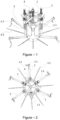
- FIG. 1 The perspective view of the invention subject valve sparing aortic root replacement device is illustrated in Figure - 1.
- FIG. 2 The top view of the invention subject valve sparing aortic root replacement device is illustrated in Figure - 2.
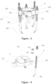
- FIG. 5 The perspective view of the commissure holders on the invention subject valve sparing aortic root replacement device is illustrated in Figure - 5.
- FIG. 7 The perspective view of the window showing the graft diameter scale on the invention subject valve protective aortic stem replacement device is illustrated in Figure - 7.
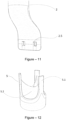
- FIG. 13 Another perspective view of the invention subject valve sparing aortic root replacement device is illustrated in Figure - 13.
- the main parts constituting the invention subject valve sparing aortic root replacement device are: an adjustable circle (1 ), legs (2), slit surgical tubes (3), cusp caliper (effective height caliper) (4).
- the main parts composing the referred adjustable circle (1 ) are: commissure holders (1 .3) clamped to the commissure (5.1) which is the point where the aortic leaflets (5.2) interconnect, circle screw (1.1) that allows for the referred commissure holders (1 .3) to approach or move away from each other by changing the diameter of the adjustable-diameter circle (1), and window (1.2) that shows the graft diameter scale, the number written on which at the position where the aortic leaflets (5.2) are positioned at the appropriate value is determined as the diameter of the artificial vessel to be chosen.
- the main parts composing the referred legs (2) are: support element (2.1) the convex surface of which sits on the inner surface of the referred adjustable circle (1) and ensures the perpendicular positioning of the legs, leg stabilizer clips (2.2) that fit into the parallel grooves on the legs (2) and ensure fixation, clip stabilizer (2.3) that disables the referred leg stabilizer clips (2.2) and allows the continuous movement of the legs (2), leg springs (2.4) that fulfill the pushing function so as to push the referred adjustable circle (1) from the aortic valve, suture holes (2.5) that ensure the referred legs (2) to stay fixed on the operation suture (3.3) that has been tensed by the slit surgical tubes (3), and the leg connectors (2.6) that allows the vertical movement of the adjustable circle (1) on the legs (2).
- the main parts composing the referred slit surgical tube (3) are: the operation suture (3.3), surgical teflon pledget (3.1) placed as spongy support material preventing the referred operation suture (3.3) from cutting the tissue, the surgical tube stopper that wraps the output end of the referred operation suture (3.3) from the outside and forms support.
- the main parts composing the referred cusp caliper (effective height caliper) (4) are: cusp caliper pins (4.1) that have millimeter scale placed on them, cusp caliper clips (4.2) that fixes the referred cusp caliper pins (4.1), cusp caliper pins (4.1) that perform measurement for each aortic leaflet (5.2) and pin pulling springs (4.3) that fulfill the function of pulling the referred pin endings (4.4).
- the main parts composing the referred aortic annulus (5) are: aortic leaflets (5.2) that connect at the center point and form the aortic valve and commissure (5.1) connected as the binary connection places of the referred aortic valves (5.2).
- the adjustable circle (1) is brought to the maximum width using the circle screw (1.1).
- each leg stabilizer clips (2.2) is placed in the clip stabilizers (2.3) groove that has been made for it by turning clockwise.
- the referred leg springs (2.4) push the adjustable- circle (1) so as to move it away from the aortic valve.
- the strength of the referred leg springs (2.4) is equal to the force by which the surgeon lifts the aortic leaflets (5.2) by pulling with handle forceps and the suture. In other words, they do not have a suspension force that will make any damages in the tissues.
- the referred legs (2) are in continuously movable position. From the 12 operation sutures (3.3) placed as standard, total 10 needles of the 5 critical operation sutures (3.3) that are always fixed and selected for every patient are passed through the suture holes (2.5) on the 5 legs (2) that correspond to them, and are suspended.
- the referred surgical teflon pledget (3.1) is positioned as the spongy support material that prevents the operation suture (3.3) from cutting the tissue.
- the invention subject valve sparing aortic root replacement device is suspended, and moved to the aortic root as guided by the operation suture (3.3).
- the referred slit surgical tubes (3) are placed on the referred 5 operation sutures (3.3).
- the referred slit surgical tubes (3) are moved through the suture holes (2.5) on the referred legs (2) and the surgical tube stopper (3.2) are closed. Under these circumstances, there are 5 slit siners (3) on the 5 measuring legs (2). But, the referred slit surgical tubes (3) have not yet been tightened.
- the referred adjustable circle (1) is slowly contracted and pushed towards the root tissue through the tensing of the operation sutures (3.3) by all slit surgical tubes at the point where the suture holes (2.5) on all legs (2) touch the aortic root tissue.
- the 5 legs (2) are fixed between the slit surgical tubes (3) and the root tissue, at the level of the operation suture (3.3).
- the referred adjustable circle (1) is pushed towards the aortic root and the commissure holders (1.3) are fixed to the aortic leaflet connections called aortic commissure (5.1 ).
- the referred valve sparing aortic root replacement device is slowly released so that it is positioned.
- the aortic commissures rise and remain suspended, and at this point, the movement of the device is limited at the point where the referred commissure holders (1.3) suspend the aortic commissures (5.1).
- leg stabilizer clips (2.2) on each leg (2) are released and it is ensured that each leg (2) is fixed. Now, the aortic valve is suspended with its three-dimensional structure, as it should naturally be.
- the central coaptations of the aortic leaflets (5.2) are ensured by narrowing the adjustable circle (1).
- the height of the aortic leaflet (5.2)(effective height value) is measured over and over again using the cusp caliper (effective height caliper) (4).
- the referred pin pulling springs (4.3) operates by pulling the pin endings (4.4).
- the pin endings (4.4) are positioned at the farthest point to the aortic leaflets (5.2), and resume their starting positions for a new measurement.
- the referred legs (2) are fixed and. thus show the positions of the 5 operation sutures (3.3).
- the referred commissure holders (1.3) are opened and the aortic valve structure is released.
- the referred surgical tube stoppers (3.2) are opened and the slit surgical tubes (3) are taken off the operation sutures (3.3).
- the referred device is detached from the operation sutures (3.3) and moved away from the patient.
- valve sparing aortic root replacement device holds all the measurements.
- the graft taken at the diameter indicated by the valve sparing aortic root replacement device is passed through the legs (2) of the device that are in the hand of the surgeon and attached to the commissure holders (1.3) at the same depth (5mm).
- the suture holes (2.5) on the legs (2) are marked on the graft.
- the places where the 3 aortic commissures (5.1) will be sutured on the graft are defined by marking the bottom points of the commissure holders (1.3).
- the graft is removed from the referred device, the other sutures are placed sequentially in between the points marked on the graft.
- the referred functional aortic annulus (5) has a 3-dimensional structure.
- the referred aortic commissure (5.1) and aortic leaflets (5.2) are structures of the referred functional aortic annulus (5).
- the referred three aortic commissures (5.1) and the three aortic leaflets (5.2) are connected as binary connection.
- the referred functional aortic annulus (5) is fully inserted into the artificial vessel (graft).
- the three commissures (5.1) are suspended in the artificial vessel and sutured. In this way, the three-dimensional structure is reconstructed.
- the referred aortic leaflets (5.2) coapt at the center point and form the aortic valve.
- the referred aortic leaflets (5.2) prevent blood from regurgitating into the heart after the heart has pumped the blood.
- the referred support element (2.1) is tightened by the referred leg connectors (2.6).
- the referred legs (2) move inside the leg connectors (2.6).
- the tightening strength of the support element (2.1) and the leg connector (2.6) allows horizontal movements inside the groove.
- the convex surface of the referred support element (2.1) sits on the inner surface of the adjustable circle (1).
- the concave surface of the leg connector (2.6) sits on the outside of the adjustable circle.
- the tightening of the support element (2.1) and the leg holder (2.6) does not prevent the horizontal movements in the groove.
- the leg connector (2.6) always remains perpendicular and keeps the legs (2) always perpendicular.
Landscapes
- Health & Medical Sciences (AREA)
- Life Sciences & Earth Sciences (AREA)
- Cardiology (AREA)
- General Health & Medical Sciences (AREA)
- Veterinary Medicine (AREA)
- Biomedical Technology (AREA)
- Heart & Thoracic Surgery (AREA)
- Engineering & Computer Science (AREA)
- Animal Behavior & Ethology (AREA)
- Public Health (AREA)
- Surgery (AREA)
- Oral & Maxillofacial Surgery (AREA)
- Transplantation (AREA)
- Vascular Medicine (AREA)
- Nuclear Medicine, Radiotherapy & Molecular Imaging (AREA)
- Medical Informatics (AREA)
- Molecular Biology (AREA)
- Pathology (AREA)
- Prostheses (AREA)
- External Artificial Organs (AREA)
Claims (14)
- Klappenerhaltendes Aortenwurzelersatzgerät zur Verwendung bei der Operation für klappenerhaltenden Aortenwurzelersatz, die eine spezielle Operation für Wurzel der Hauptschlagader ausgehend von Herz ist oder in der Literatur als 'David-Operation' bekannt ist, dadurch gekennzeichnet, dass sie die Folgende umfasst:• einen einstellbaren Kreis (1), der vorsieht, dass die Meßschenkel (2) um die Aortenwurzel durch die einstellbare Durchmesser-Charakteristik positioniert werden, und der die Positionen von Aortenkommissuren (5.1) in verschiedenen Durchmessern konfiguriert und die Koaptationssimulation der Aortenblättchen (5.2) vorsieht;• mindestens eine Kreisschraube (1.1), die vorsieht, dass die Durchmesserwerte dieses einstellbaren Kreises (1) wie gewünscht eingestellt werden, und die auf dem einstellbaren Kreis (1) positioniert wird;• mindestens einen in Verbindung mit dem einstellbaren Kreis (1) vorgesehenen Meßschenkel (2), der die Platzierung des klappenerhaltenden Aortenwurzelersatzgerätes vorsieht, die durch die geschlitzte chirurgische Tuben und die Suturen mit der Aortenwurzel befestigt wird, und der die Orientierung der Punkten vorsieht, in denen die Suturen durch das Transplantat hindurch treten, und der dementsprechend die Vorbereitung des Transplantates vorsieht;• mindestens eine geschlitzte chirurgische Tube (3), die die Schenkel (2) des Gerätes befestigt, die in die während der Operation verwendeten Operationssuturen (3.3) platziert werden und durch Führung mittels diesen Suturen zum Aortenwurzelgewebe auf dem Niveau der Operationssuturen (3.3) in die Aortenwurzel platziert werden;• mindestens einen chirurgischen Tube-Stopfen (3.2), der das offene Ende der geschlitzten chirurgischen Tube (3) bedeckt und die Operationssutur (3.3) in gespannter Stellung presst, um die Operationssuturen (3.3) in der geschlitzten chirurgischen Tube (3) in gespannter Position zu erhalten;• mindestens einen Schwelle-Messschieber (4), die auf der Oberkante des diesen einstellbaren Kreises (1) platziert wird und orthogonal zur Aortenwurzel positioniert wird und die Höhendifferenz zwischen der Anfangskante (niedrigstes Niveau) und der freien Kante (höchstes Niveau) der jeden Aortenblättchen (5.2) geometrisch messen kann.
- Klappenerhaltendes Aortenwurzelersatzgerät nach Anspruch 1, wobei das die vaskuläre Transplantatsdurchmesser-Skala zeigende Transplantatsdurchmesser anzeigende Fenster (1.2) durch die Bestimmung der Position, in der das Aortenblättchen (5.2) auf einem geeigneten Wert positioniert wird, auf dem einstellbaren Kreis (1) positioniert wird.
- Klappenerhaltendes Aortenwurzelersatzgerät nach Anspruch 1, wobei mindestens ein Kommissurhalter (1.3), der mit dem Aortenkommissur (5.1) befestigt, die der Punkt ist, in der die Aortenblättchen (5.2) miteinander verbunden sind, in dem Körper des einstellbaren Kreises (1) vorgesehen wird.
- Klappenerhaltendes Aortenwurzelersatzgerät nach Anspruch 1, wobei ein Trägerelement (2.1) vorgesehen wird, das in der Innenfläche des einstellbaren Kreises (1) positioniert wird und vorsieht, dass die Schenkel (2) in einer senkrechten Form gehaltet werden und sich die Schenkel (2) auf dem Kreis horizontal bewegen.
- Klappenerhaltendes Aortenwurzelersatzgerät nach Anspruch 1, wobei mindestens eine Schenkelstabilisator-Klammer (2.2) vorgesehen wird, die mit den parallelen Nuten auf den Schenkel (2) verbunden ist und die Befestigung von Schenkel (2) in der Orientierung der diesen parallelen Nuten vorsieht.
- Klappenerhaltendes Aortenwurzelersatzgerät nach Anspruch 1, wobei mindestens ein Klammerstabilisator (2.3) durch Deaktivierung der Schenkelstabilisator-Klammer (2.2) eine kontinuierliche Bewegung der Schenkel (2) ermöglicht.
- Klappenerhaltendes Aortenwurzelersatzgerät nach Anspruch 1, wobei mindestens eine Schenkelfeder (2.4) an den Schenkeln (2) vorgesehen wird, die eine Schubfunktion derart verwirklicht, dass der einstellbare Kreis (1) und der Kommissurhalter (1.3) von der Aortenklappe bewegt werden, und die die Resuspension von Aortenkommissur (5.1) und die Positionierung des ganzen Gerätes innerhalb der Aortenwurzel vorsieht.
- Klappenerhaltendes Aortenwurzelersatzgerät nach Anspruch 1, wobei es mindestens ein Suturloch (2.5) umfasst, das sich innerhalb der Schenkel (2) befindet und das vorsieht, dass die Schenkel (2) mit der durch die Schenkel hindurchtretenden und gespannten Operationssutur (3.3) befestigt werden.
- Klappenerhaltendes Aortenwurzelersatzgerät nach Anspruch 1, wobei mindestens ein Schenkelverbinder (2.6) innerhalb des einstellbaren Kreises (1) vorgesehen wird, der vorsieht, dass sich der einstellbare Kreis (1) auf den Schenkeln (2) bewegen.
- Klappenerhaltendes Aortenwurzelersatzgerät nach Anspruch 1, wobei es mindestens ein chirurgischer Teflon-Tupfer (3.1) umfasst, der verhindert, dass die Operationssutur (3.3) das Gewebe schneidet, und der als schwammiges Trägermaterial verwendet wird.
- Klappenerhaltendes Aortenwurzelersatzgerät nach Anspruch 1, wobei mindestens ein Stift von Schwelle-Messschieber (4.1) vorgesehen wird, der mit dem Schwelle-Messschieber (4) verbunden ist und der vorsieht, dass durch die auf diesem Stift von Schwelle-Messschieber (4.1) vorhandene Millimeter-Skala die Höhendifferenz zwischen der Anfangskante und der freien Kante der Aortenblättchen (5.2) geometrisch gemessen wird.
- Klappenerhaltendes Aortenwurzelersatzgerät nach Anspruch 1, wobei diese Stifte von Schwelle-Messschieber (4.1) mindestens eine Schwelle-Messschiebersklammer (4.2) umfassen, die vorsieht, dass diese Stifte stationär bleiben und in die Ausgangsposition gebracht zu werden.
- Klappenerhaltendes Aortenwurzelersatzgerät nach Anspruch 1, wobei mindestens ein Stiftende (4.4) innerhalb des Körpers des Schwelle-Messschiebers (4) vorgesehen wird, das für alle Aortenblättchen (5.2) Messung durchführt.
- Klappenerhaltendes Aortenwurzelersatzgerät nach Anspruch 1, wobei mindestens eine Stiftabziehfeder (4.3), die die Funktion für Ziehen dieser Stiftenden (4.4) zur Ausgangsposition durchführt, innerhalb des Körpers der Stiften von Schwelle-Messschieber (4.1) vorgesehen wird.
Applications Claiming Priority (2)
| Application Number | Priority Date | Filing Date | Title |
|---|---|---|---|
| TR2016/18240A TR201618240A2 (tr) | 2016-12-09 | 2016-12-09 | Aort kapak koruyucu kök replasman ameli̇yatlarinda kullanilan ölçüm ve si̇mülasyon terti̇bati |
| PCT/TR2017/050610 WO2019054961A2 (en) | 2016-12-09 | 2017-11-29 | MEASURING AND SIMULATION DEVICE USED FOR AORTIC ROOT REPLACEMENT OPERATIONS WITH VALVULAR AORTIC CONSERVATION |
Publications (4)
| Publication Number | Publication Date |
|---|---|
| EP3551130A2 EP3551130A2 (de) | 2019-10-16 |
| EP3551130A4 EP3551130A4 (de) | 2019-12-11 |
| EP3551130C0 EP3551130C0 (de) | 2023-11-22 |
| EP3551130B1 true EP3551130B1 (de) | 2023-11-22 |
Family
ID=63833624
Family Applications (1)
| Application Number | Title | Priority Date | Filing Date |
|---|---|---|---|
| EP17925444.6A Active EP3551130B1 (de) | 2016-12-09 | 2017-11-29 | Mess- und simulationsvorrichtung für herzklappenerhaltende aortenwurzelaustauschoperationen |
Country Status (4)
| Country | Link |
|---|---|
| US (1) | US11351029B2 (de) |
| EP (1) | EP3551130B1 (de) |
| TR (1) | TR201618240A2 (de) |
| WO (1) | WO2019054961A2 (de) |
Families Citing this family (9)
| Publication number | Priority date | Publication date | Assignee | Title |
|---|---|---|---|---|
| KR102838870B1 (ko) | 2020-06-09 | 2025-07-24 | 화이자 인코포레이티드 | 멜라노코르틴 4 수용체 길항제로서의 스피로 화합물 및 그의 용도 |
| WO2023026180A1 (en) | 2021-08-26 | 2023-03-02 | Pfizer Inc. | Amorphous form of (s)-2-(5-((3-ethoxypyridin-2-yl)oxy)pyridin-3-yl)-n-(tetrahydrofuran-3- yl)pyrimidine-5-carboxamide |
| JP2025535295A (ja) | 2022-10-18 | 2025-10-24 | ファイザー・インク | パタチン様ホスホリパーゼドメイン含有タンパク質3(pnpla3)修飾因子 |
| CR20250437A (es) | 2023-04-14 | 2025-12-09 | Pfizer | Antagonistas del receptor de polipéptido insulinotrópico dependiente de glucosa y usos de estos |
| TW202539633A (zh) | 2024-02-01 | 2025-10-16 | 美商輝瑞股份有限公司 | 葡萄糖依賴性促胰島素多肽受體拮抗劑及其用途 |
| WO2025224599A1 (en) | 2024-04-22 | 2025-10-30 | Pfizer Inc. | Pyrrolidine-based glucose-dependent insulinotropic polypeptide receptor antagonists and uses thereof |
| WO2026013531A1 (en) | 2024-07-10 | 2026-01-15 | Pfizer Inc. | Spiro[2.5]octane compounds |
| WO2026033382A1 (en) | 2024-08-07 | 2026-02-12 | Pfizer Inc. | Heterocyclic glp-1r modulators |
| WO2026042018A1 (en) | 2024-08-21 | 2026-02-26 | Pfizer Inc. | 4-{4-[(1-{[4-(propan-2-yl)phenyl]carbamoyl)-d-prolyl)amino]cyclohexyl}benzoic acid derivatives as gipr antagonists for the treatment of diabetes |
Family Cites Families (16)
| Publication number | Priority date | Publication date | Assignee | Title |
|---|---|---|---|---|
| US5716370A (en) | 1996-02-23 | 1998-02-10 | Williamson, Iv; Warren | Means for replacing a heart valve in a minimally invasive manner |
| US6494889B1 (en) * | 1999-09-01 | 2002-12-17 | Converge Medical, Inc. | Additional sutureless anastomosis embodiments |
| US6598307B2 (en) * | 1999-11-17 | 2003-07-29 | Jack W. Love | Device and method for assessing the geometry of a heart valve |
| CN1243520C (zh) | 2000-01-14 | 2006-03-01 | 维亚科公司 | 组织瓣环成形术带 |
| DE10010074B4 (de) | 2000-02-28 | 2005-04-14 | Fraunhofer-Gesellschaft zur Förderung der angewandten Forschung e.V. | Vorrichtung zur Befestigung und Verankerung von Herzklappenprothesen |
| DE102005003632A1 (de) | 2005-01-20 | 2006-08-17 | Fraunhofer-Gesellschaft zur Förderung der angewandten Forschung e.V. | Katheter für die transvaskuläre Implantation von Herzklappenprothesen |
| US20090299469A1 (en) | 2008-05-27 | 2009-12-03 | The Board Of Regents Of The University Of Texas System | Cone-shaped aortic root replacement graft and methods for making and using same |
| US8317696B2 (en) * | 2008-12-15 | 2012-11-27 | Coroneo, Inc. | Surgical tool for measurement of valve annulus and cusp geometry |
| US8715207B2 (en) * | 2009-03-19 | 2014-05-06 | Sorin Group Italia S.R.L. | Universal valve annulus sizing device |
| US10028834B2 (en) * | 2011-01-31 | 2018-07-24 | St. Jude Medical, Inc. | Adjustable prosthetic anatomical device holder and handle for the implantation of an annuloplasty ring |
| US10182913B2 (en) * | 2012-10-12 | 2019-01-22 | Nikola Dobrilovic | Heart valve sizing ring for valve-sparing aortic root remodeling procedures |
| US9468527B2 (en) * | 2013-06-12 | 2016-10-18 | Edwards Lifesciences Corporation | Cardiac implant with integrated suture fasteners |
| US9622863B2 (en) | 2013-11-22 | 2017-04-18 | Edwards Lifesciences Corporation | Aortic insufficiency repair device and method |
| US9180005B1 (en) * | 2014-07-17 | 2015-11-10 | Millipede, Inc. | Adjustable endolumenal mitral valve ring |
| US20190015191A1 (en) * | 2017-07-17 | 2019-01-17 | Denis BERDAJS | Prosthetic aortic root replacement graft |
| US11071626B2 (en) * | 2018-03-16 | 2021-07-27 | W. L. Gore & Associates, Inc. | Diametric expansion features for prosthetic valves |
-
2016
- 2016-12-09 TR TR2016/18240A patent/TR201618240A2/tr unknown
-
2017
- 2017-11-29 EP EP17925444.6A patent/EP3551130B1/de active Active
- 2017-11-29 US US16/467,204 patent/US11351029B2/en active Active
- 2017-11-29 WO PCT/TR2017/050610 patent/WO2019054961A2/en not_active Ceased
Also Published As
| Publication number | Publication date |
|---|---|
| EP3551130A2 (de) | 2019-10-16 |
| EP3551130A4 (de) | 2019-12-11 |
| WO2019054961A3 (en) | 2019-05-23 |
| US11351029B2 (en) | 2022-06-07 |
| TR201618240A2 (tr) | 2017-01-23 |
| US20200085581A1 (en) | 2020-03-19 |
| EP3551130C0 (de) | 2023-11-22 |
| WO2019054961A2 (en) | 2019-03-21 |
Similar Documents
| Publication | Publication Date | Title |
|---|---|---|
| EP3551130B1 (de) | Mess- und simulationsvorrichtung für herzklappenerhaltende aortenwurzelaustauschoperationen | |
| AU2004285424B2 (en) | Attachment device and methods of using the same | |
| US9005279B2 (en) | Beating heart buttress and implantation method to prevent prolapse of a heart valve | |
| US9662208B2 (en) | Devices and methods for surgical and percutaneous repair of heart valve lesions | |
| US20040059413A1 (en) | Suture template for facilitating implantation of a prosthetic heart valve | |
| US20060106415A1 (en) | Apparatus to facilitate implantation | |
| US6719785B2 (en) | Aortic heart valve prosthesis implantation tool | |
| WO2008066987A2 (en) | Apparatus, system, and method for delivering an annuloplasty ring | |
| EP0873094A1 (de) | Obturator zum kalibrieren von künstlichen aortenklappen | |
| JP2004510493A (ja) | 最小侵襲性の弁輪形成修復セグメント送達テンプレートシステム | |
| WO2000064382A2 (en) | Aortic heart valve prosthesis sizer and marker | |
| KR20240055007A (ko) | 인공 판막용 맞교차 정렬 시스템 및 정렬 방법 | |
| KR20210016360A (ko) | 주사기용 제거 가능한 체적 표시기 | |
| US20240081995A1 (en) | Self-expandable prosthetic heart valve |
Legal Events
| Date | Code | Title | Description |
|---|---|---|---|
| STAA | Information on the status of an ep patent application or granted ep patent |
Free format text: STATUS: THE INTERNATIONAL PUBLICATION HAS BEEN MADE |
|
| PUAI | Public reference made under article 153(3) epc to a published international application that has entered the european phase |
Free format text: ORIGINAL CODE: 0009012 |
|
| STAA | Information on the status of an ep patent application or granted ep patent |
Free format text: STATUS: REQUEST FOR EXAMINATION WAS MADE |
|
| 17P | Request for examination filed |
Effective date: 20190531 |
|
| AK | Designated contracting states |
Kind code of ref document: A2 Designated state(s): AL AT BE BG CH CY CZ DE DK EE ES FI FR GB GR HR HU IE IS IT LI LT LU LV MC MK MT NL NO PL PT RO RS SE SI SK SM TR |
|
| AX | Request for extension of the european patent |
Extension state: BA ME |
|
| A4 | Supplementary search report drawn up and despatched |
Effective date: 20191113 |
|
| RIC1 | Information provided on ipc code assigned before grant |
Ipc: A61B 17/04 20060101ALI20191107BHEP Ipc: A61F 2/24 20060101AFI20191107BHEP Ipc: A61B 17/11 20060101ALI20191107BHEP Ipc: A61F 2/07 20130101ALI20191107BHEP |
|
| DAV | Request for validation of the european patent (deleted) | ||
| DAX | Request for extension of the european patent (deleted) | ||
| STAA | Information on the status of an ep patent application or granted ep patent |
Free format text: STATUS: EXAMINATION IS IN PROGRESS |
|
| 17Q | First examination report despatched |
Effective date: 20220214 |
|
| GRAP | Despatch of communication of intention to grant a patent |
Free format text: ORIGINAL CODE: EPIDOSNIGR1 |
|
| STAA | Information on the status of an ep patent application or granted ep patent |
Free format text: STATUS: GRANT OF PATENT IS INTENDED |
|
| INTG | Intention to grant announced |
Effective date: 20230619 |
|
| GRAS | Grant fee paid |
Free format text: ORIGINAL CODE: EPIDOSNIGR3 |
|
| GRAA | (expected) grant |
Free format text: ORIGINAL CODE: 0009210 |
|
| STAA | Information on the status of an ep patent application or granted ep patent |
Free format text: STATUS: THE PATENT HAS BEEN GRANTED |
|
| AK | Designated contracting states |
Kind code of ref document: B1 Designated state(s): AL AT BE BG CH CY CZ DE DK EE ES FI FR GB GR HR HU IE IS IT LI LT LU LV MC MK MT NL NO PL PT RO RS SE SI SK SM TR |
|
| REG | Reference to a national code |
Ref country code: GB Ref legal event code: FG4D |
|
| REG | Reference to a national code |
Ref country code: CH Ref legal event code: EP |
|
| REG | Reference to a national code |
Ref country code: DE Ref legal event code: R096 Ref document number: 602017076880 Country of ref document: DE |
|
| REG | Reference to a national code |
Ref country code: IE Ref legal event code: FG4D |
|
| U01 | Request for unitary effect filed |
Effective date: 20231219 |
|
| U07 | Unitary effect registered |
Designated state(s): AT BE BG DE DK EE FI FR IT LT LU LV MT NL PT SE SI Effective date: 20240102 |
|
| U20 | Renewal fee for the european patent with unitary effect paid |
Year of fee payment: 7 Effective date: 20240125 |
|
| PG25 | Lapsed in a contracting state [announced via postgrant information from national office to epo] |
Ref country code: GR Free format text: LAPSE BECAUSE OF FAILURE TO SUBMIT A TRANSLATION OF THE DESCRIPTION OR TO PAY THE FEE WITHIN THE PRESCRIBED TIME-LIMIT Effective date: 20240223 |
|
| PG25 | Lapsed in a contracting state [announced via postgrant information from national office to epo] |
Ref country code: IS Free format text: LAPSE BECAUSE OF FAILURE TO SUBMIT A TRANSLATION OF THE DESCRIPTION OR TO PAY THE FEE WITHIN THE PRESCRIBED TIME-LIMIT Effective date: 20240322 |
|
| PG25 | Lapsed in a contracting state [announced via postgrant information from national office to epo] |
Ref country code: ES Free format text: LAPSE BECAUSE OF FAILURE TO SUBMIT A TRANSLATION OF THE DESCRIPTION OR TO PAY THE FEE WITHIN THE PRESCRIBED TIME-LIMIT Effective date: 20231122 |
|
| PG25 | Lapsed in a contracting state [announced via postgrant information from national office to epo] |
Ref country code: IS Free format text: LAPSE BECAUSE OF FAILURE TO SUBMIT A TRANSLATION OF THE DESCRIPTION OR TO PAY THE FEE WITHIN THE PRESCRIBED TIME-LIMIT Effective date: 20240322 Ref country code: GR Free format text: LAPSE BECAUSE OF FAILURE TO SUBMIT A TRANSLATION OF THE DESCRIPTION OR TO PAY THE FEE WITHIN THE PRESCRIBED TIME-LIMIT Effective date: 20240223 Ref country code: ES Free format text: LAPSE BECAUSE OF FAILURE TO SUBMIT A TRANSLATION OF THE DESCRIPTION OR TO PAY THE FEE WITHIN THE PRESCRIBED TIME-LIMIT Effective date: 20231122 |
|
| PG25 | Lapsed in a contracting state [announced via postgrant information from national office to epo] |
Ref country code: RS Free format text: LAPSE BECAUSE OF FAILURE TO SUBMIT A TRANSLATION OF THE DESCRIPTION OR TO PAY THE FEE WITHIN THE PRESCRIBED TIME-LIMIT Effective date: 20231122 Ref country code: PL Free format text: LAPSE BECAUSE OF FAILURE TO SUBMIT A TRANSLATION OF THE DESCRIPTION OR TO PAY THE FEE WITHIN THE PRESCRIBED TIME-LIMIT Effective date: 20231122 Ref country code: NO Free format text: LAPSE BECAUSE OF FAILURE TO SUBMIT A TRANSLATION OF THE DESCRIPTION OR TO PAY THE FEE WITHIN THE PRESCRIBED TIME-LIMIT Effective date: 20240222 Ref country code: HR Free format text: LAPSE BECAUSE OF FAILURE TO SUBMIT A TRANSLATION OF THE DESCRIPTION OR TO PAY THE FEE WITHIN THE PRESCRIBED TIME-LIMIT Effective date: 20231122 |
|
| PG25 | Lapsed in a contracting state [announced via postgrant information from national office to epo] |
Ref country code: CZ Free format text: LAPSE BECAUSE OF FAILURE TO SUBMIT A TRANSLATION OF THE DESCRIPTION OR TO PAY THE FEE WITHIN THE PRESCRIBED TIME-LIMIT Effective date: 20231122 |
|
| PG25 | Lapsed in a contracting state [announced via postgrant information from national office to epo] |
Ref country code: SK Free format text: LAPSE BECAUSE OF FAILURE TO SUBMIT A TRANSLATION OF THE DESCRIPTION OR TO PAY THE FEE WITHIN THE PRESCRIBED TIME-LIMIT Effective date: 20231122 |
|
| PG25 | Lapsed in a contracting state [announced via postgrant information from national office to epo] |
Ref country code: SM Free format text: LAPSE BECAUSE OF FAILURE TO SUBMIT A TRANSLATION OF THE DESCRIPTION OR TO PAY THE FEE WITHIN THE PRESCRIBED TIME-LIMIT Effective date: 20231122 Ref country code: SK Free format text: LAPSE BECAUSE OF FAILURE TO SUBMIT A TRANSLATION OF THE DESCRIPTION OR TO PAY THE FEE WITHIN THE PRESCRIBED TIME-LIMIT Effective date: 20231122 Ref country code: RO Free format text: LAPSE BECAUSE OF FAILURE TO SUBMIT A TRANSLATION OF THE DESCRIPTION OR TO PAY THE FEE WITHIN THE PRESCRIBED TIME-LIMIT Effective date: 20231122 Ref country code: CZ Free format text: LAPSE BECAUSE OF FAILURE TO SUBMIT A TRANSLATION OF THE DESCRIPTION OR TO PAY THE FEE WITHIN THE PRESCRIBED TIME-LIMIT Effective date: 20231122 |
|
| REG | Reference to a national code |
Ref country code: DE Ref legal event code: R097 Ref document number: 602017076880 Country of ref document: DE |
|
| PG25 | Lapsed in a contracting state [announced via postgrant information from national office to epo] |
Ref country code: MC Free format text: LAPSE BECAUSE OF FAILURE TO SUBMIT A TRANSLATION OF THE DESCRIPTION OR TO PAY THE FEE WITHIN THE PRESCRIBED TIME-LIMIT Effective date: 20231122 |
|
| PG25 | Lapsed in a contracting state [announced via postgrant information from national office to epo] |
Ref country code: MC Free format text: LAPSE BECAUSE OF FAILURE TO SUBMIT A TRANSLATION OF THE DESCRIPTION OR TO PAY THE FEE WITHIN THE PRESCRIBED TIME-LIMIT Effective date: 20231122 |
|
| PLBE | No opposition filed within time limit |
Free format text: ORIGINAL CODE: 0009261 |
|
| STAA | Information on the status of an ep patent application or granted ep patent |
Free format text: STATUS: NO OPPOSITION FILED WITHIN TIME LIMIT |
|
| 26N | No opposition filed |
Effective date: 20240823 |
|
| U20 | Renewal fee for the european patent with unitary effect paid |
Year of fee payment: 8 Effective date: 20241003 |
|
| PG25 | Lapsed in a contracting state [announced via postgrant information from national office to epo] |
Ref country code: CY Free format text: LAPSE BECAUSE OF FAILURE TO SUBMIT A TRANSLATION OF THE DESCRIPTION OR TO PAY THE FEE WITHIN THE PRESCRIBED TIME-LIMIT; INVALID AB INITIO Effective date: 20171129 |
|
| PG25 | Lapsed in a contracting state [announced via postgrant information from national office to epo] |
Ref country code: HU Free format text: LAPSE BECAUSE OF FAILURE TO SUBMIT A TRANSLATION OF THE DESCRIPTION OR TO PAY THE FEE WITHIN THE PRESCRIBED TIME-LIMIT; INVALID AB INITIO Effective date: 20171129 |
|
| PGFP | Annual fee paid to national office [announced via postgrant information from national office to epo] |
Ref country code: GB Payment date: 20250923 Year of fee payment: 9 |
|
| PGFP | Annual fee paid to national office [announced via postgrant information from national office to epo] |
Ref country code: IE Payment date: 20250924 Year of fee payment: 9 |
|
| REG | Reference to a national code |
Ref country code: CH Ref legal event code: U11 Free format text: ST27 STATUS EVENT CODE: U-0-0-U10-U11 (AS PROVIDED BY THE NATIONAL OFFICE) Effective date: 20251201 |
|
| PG25 | Lapsed in a contracting state [announced via postgrant information from national office to epo] |
Ref country code: TR Free format text: LAPSE BECAUSE OF FAILURE TO SUBMIT A TRANSLATION OF THE DESCRIPTION OR TO PAY THE FEE WITHIN THE PRESCRIBED TIME-LIMIT Effective date: 20231122 |
|
| U20 | Renewal fee for the european patent with unitary effect paid |
Year of fee payment: 9 Effective date: 20251127 |
|
| PGFP | Annual fee paid to national office [announced via postgrant information from national office to epo] |
Ref country code: CH Payment date: 20251201 Year of fee payment: 9 |