EP3550694A1 - Battery pack charging system - Google Patents
Battery pack charging system Download PDFInfo
- Publication number
- EP3550694A1 EP3550694A1 EP17877898.1A EP17877898A EP3550694A1 EP 3550694 A1 EP3550694 A1 EP 3550694A1 EP 17877898 A EP17877898 A EP 17877898A EP 3550694 A1 EP3550694 A1 EP 3550694A1
- Authority
- EP
- European Patent Office
- Prior art keywords
- battery pack
- signal
- charging device
- state
- port
- Prior art date
- Legal status (The legal status is an assumption and is not a legal conclusion. Google has not performed a legal analysis and makes no representation as to the accuracy of the status listed.)
- Pending
Links
Images


Classifications
-
- B—PERFORMING OPERATIONS; TRANSPORTING
- B60—VEHICLES IN GENERAL
- B60L—PROPULSION OF ELECTRICALLY-PROPELLED VEHICLES; SUPPLYING ELECTRIC POWER FOR AUXILIARY EQUIPMENT OF ELECTRICALLY-PROPELLED VEHICLES; ELECTRODYNAMIC BRAKE SYSTEMS FOR VEHICLES IN GENERAL; MAGNETIC SUSPENSION OR LEVITATION FOR VEHICLES; MONITORING OPERATING VARIABLES OF ELECTRICALLY-PROPELLED VEHICLES; ELECTRIC SAFETY DEVICES FOR ELECTRICALLY-PROPELLED VEHICLES
- B60L53/00—Methods of charging batteries, specially adapted for electric vehicles; Charging stations or on-board charging equipment therefor; Exchange of energy storage elements in electric vehicles
- B60L53/60—Monitoring or controlling charging stations
- B60L53/62—Monitoring or controlling charging stations in response to charging parameters, e.g. current, voltage or electrical charge
-
- B—PERFORMING OPERATIONS; TRANSPORTING
- B60—VEHICLES IN GENERAL
- B60L—PROPULSION OF ELECTRICALLY-PROPELLED VEHICLES; SUPPLYING ELECTRIC POWER FOR AUXILIARY EQUIPMENT OF ELECTRICALLY-PROPELLED VEHICLES; ELECTRODYNAMIC BRAKE SYSTEMS FOR VEHICLES IN GENERAL; MAGNETIC SUSPENSION OR LEVITATION FOR VEHICLES; MONITORING OPERATING VARIABLES OF ELECTRICALLY-PROPELLED VEHICLES; ELECTRIC SAFETY DEVICES FOR ELECTRICALLY-PROPELLED VEHICLES
- B60L50/00—Electric propulsion with power supplied within the vehicle
- B60L50/50—Electric propulsion with power supplied within the vehicle using propulsion power supplied by batteries or fuel cells
- B60L50/60—Electric propulsion with power supplied within the vehicle using propulsion power supplied by batteries or fuel cells using power supplied by batteries
- B60L50/64—Constructional details of batteries specially adapted for electric vehicles
-
- B—PERFORMING OPERATIONS; TRANSPORTING
- B60—VEHICLES IN GENERAL
- B60L—PROPULSION OF ELECTRICALLY-PROPELLED VEHICLES; SUPPLYING ELECTRIC POWER FOR AUXILIARY EQUIPMENT OF ELECTRICALLY-PROPELLED VEHICLES; ELECTRODYNAMIC BRAKE SYSTEMS FOR VEHICLES IN GENERAL; MAGNETIC SUSPENSION OR LEVITATION FOR VEHICLES; MONITORING OPERATING VARIABLES OF ELECTRICALLY-PROPELLED VEHICLES; ELECTRIC SAFETY DEVICES FOR ELECTRICALLY-PROPELLED VEHICLES
- B60L53/00—Methods of charging batteries, specially adapted for electric vehicles; Charging stations or on-board charging equipment therefor; Exchange of energy storage elements in electric vehicles
-
- B—PERFORMING OPERATIONS; TRANSPORTING
- B60—VEHICLES IN GENERAL
- B60L—PROPULSION OF ELECTRICALLY-PROPELLED VEHICLES; SUPPLYING ELECTRIC POWER FOR AUXILIARY EQUIPMENT OF ELECTRICALLY-PROPELLED VEHICLES; ELECTRODYNAMIC BRAKE SYSTEMS FOR VEHICLES IN GENERAL; MAGNETIC SUSPENSION OR LEVITATION FOR VEHICLES; MONITORING OPERATING VARIABLES OF ELECTRICALLY-PROPELLED VEHICLES; ELECTRIC SAFETY DEVICES FOR ELECTRICALLY-PROPELLED VEHICLES
- B60L53/00—Methods of charging batteries, specially adapted for electric vehicles; Charging stations or on-board charging equipment therefor; Exchange of energy storage elements in electric vehicles
- B60L53/60—Monitoring or controlling charging stations
- B60L53/66—Data transfer between charging stations and vehicles
-
- B—PERFORMING OPERATIONS; TRANSPORTING
- B60—VEHICLES IN GENERAL
- B60L—PROPULSION OF ELECTRICALLY-PROPELLED VEHICLES; SUPPLYING ELECTRIC POWER FOR AUXILIARY EQUIPMENT OF ELECTRICALLY-PROPELLED VEHICLES; ELECTRODYNAMIC BRAKE SYSTEMS FOR VEHICLES IN GENERAL; MAGNETIC SUSPENSION OR LEVITATION FOR VEHICLES; MONITORING OPERATING VARIABLES OF ELECTRICALLY-PROPELLED VEHICLES; ELECTRIC SAFETY DEVICES FOR ELECTRICALLY-PROPELLED VEHICLES
- B60L58/00—Methods or circuit arrangements for monitoring or controlling batteries or fuel cells, specially adapted for electric vehicles
- B60L58/10—Methods or circuit arrangements for monitoring or controlling batteries or fuel cells, specially adapted for electric vehicles for monitoring or controlling batteries
- B60L58/12—Methods or circuit arrangements for monitoring or controlling batteries or fuel cells, specially adapted for electric vehicles for monitoring or controlling batteries responding to state of charge [SoC]
-
- B—PERFORMING OPERATIONS; TRANSPORTING
- B60—VEHICLES IN GENERAL
- B60R—VEHICLES, VEHICLE FITTINGS, OR VEHICLE PARTS, NOT OTHERWISE PROVIDED FOR
- B60R16/00—Electric or fluid circuits specially adapted for vehicles and not otherwise provided for; Arrangement of elements of electric or fluid circuits specially adapted for vehicles and not otherwise provided for
- B60R16/02—Electric or fluid circuits specially adapted for vehicles and not otherwise provided for; Arrangement of elements of electric or fluid circuits specially adapted for vehicles and not otherwise provided for electric constitutive elements
- B60R16/03—Electric or fluid circuits specially adapted for vehicles and not otherwise provided for; Arrangement of elements of electric or fluid circuits specially adapted for vehicles and not otherwise provided for electric constitutive elements for supply of electrical power to vehicle subsystems or for
-
- H—ELECTRICITY
- H01—ELECTRIC ELEMENTS
- H01M—PROCESSES OR MEANS, e.g. BATTERIES, FOR THE DIRECT CONVERSION OF CHEMICAL ENERGY INTO ELECTRICAL ENERGY
- H01M10/00—Secondary cells; Manufacture thereof
- H01M10/42—Methods or arrangements for servicing or maintenance of secondary cells or secondary half-cells
- H01M10/44—Methods for charging or discharging
-
- H—ELECTRICITY
- H01—ELECTRIC ELEMENTS
- H01M—PROCESSES OR MEANS, e.g. BATTERIES, FOR THE DIRECT CONVERSION OF CHEMICAL ENERGY INTO ELECTRICAL ENERGY
- H01M50/00—Constructional details or processes of manufacture of the non-active parts of electrochemical cells other than fuel cells, e.g. hybrid cells
- H01M50/20—Mountings; Secondary casings or frames; Racks, modules or packs; Suspension devices; Shock absorbers; Transport or carrying devices; Holders
- H01M50/249—Mountings; Secondary casings or frames; Racks, modules or packs; Suspension devices; Shock absorbers; Transport or carrying devices; Holders specially adapted for aircraft or vehicles, e.g. cars or trains
-
- H—ELECTRICITY
- H02—GENERATION; CONVERSION OR DISTRIBUTION OF ELECTRIC POWER
- H02J—ELECTRIC POWER NETWORKS; CIRCUIT ARRANGEMENTS OR SYSTEMS FOR SUPPLYING OR DISTRIBUTING ELECTRIC POWER; SYSTEMS FOR STORING ELECTRIC ENERGY
- H02J7/00—Circuit arrangements for charging or discharging batteries or for supplying loads from batteries
-
- H—ELECTRICITY
- H02—GENERATION; CONVERSION OR DISTRIBUTION OF ELECTRIC POWER
- H02J—ELECTRIC POWER NETWORKS; CIRCUIT ARRANGEMENTS OR SYSTEMS FOR SUPPLYING OR DISTRIBUTING ELECTRIC POWER; SYSTEMS FOR STORING ELECTRIC ENERGY
- H02J7/00—Circuit arrangements for charging or discharging batteries or for supplying loads from batteries
- H02J7/02—Circuit arrangements for charging or discharging batteries or for supplying loads from batteries for charging batteries from AC mains by converters
-
- H—ELECTRICITY
- H02—GENERATION; CONVERSION OR DISTRIBUTION OF ELECTRIC POWER
- H02J—ELECTRIC POWER NETWORKS; CIRCUIT ARRANGEMENTS OR SYSTEMS FOR SUPPLYING OR DISTRIBUTING ELECTRIC POWER; SYSTEMS FOR STORING ELECTRIC ENERGY
- H02J7/00—Circuit arrangements for charging or discharging batteries or for supplying loads from batteries
- H02J7/90—Regulation of charging or discharging current or voltage
- H02J7/96—Regulation of charging or discharging current or voltage in response to battery voltage
-
- B—PERFORMING OPERATIONS; TRANSPORTING
- B60—VEHICLES IN GENERAL
- B60L—PROPULSION OF ELECTRICALLY-PROPELLED VEHICLES; SUPPLYING ELECTRIC POWER FOR AUXILIARY EQUIPMENT OF ELECTRICALLY-PROPELLED VEHICLES; ELECTRODYNAMIC BRAKE SYSTEMS FOR VEHICLES IN GENERAL; MAGNETIC SUSPENSION OR LEVITATION FOR VEHICLES; MONITORING OPERATING VARIABLES OF ELECTRICALLY-PROPELLED VEHICLES; ELECTRIC SAFETY DEVICES FOR ELECTRICALLY-PROPELLED VEHICLES
- B60L2240/00—Control parameters of input or output; Target parameters
- B60L2240/40—Drive Train control parameters
- B60L2240/54—Drive Train control parameters related to batteries
- B60L2240/549—Current
-
- H—ELECTRICITY
- H01—ELECTRIC ELEMENTS
- H01M—PROCESSES OR MEANS, e.g. BATTERIES, FOR THE DIRECT CONVERSION OF CHEMICAL ENERGY INTO ELECTRICAL ENERGY
- H01M10/00—Secondary cells; Manufacture thereof
- H01M10/42—Methods or arrangements for servicing or maintenance of secondary cells or secondary half-cells
- H01M10/425—Structural combination with electronic components, e.g. electronic circuits integrated to the outside of the casing
-
- H—ELECTRICITY
- H01—ELECTRIC ELEMENTS
- H01M—PROCESSES OR MEANS, e.g. BATTERIES, FOR THE DIRECT CONVERSION OF CHEMICAL ENERGY INTO ELECTRICAL ENERGY
- H01M10/00—Secondary cells; Manufacture thereof
- H01M10/42—Methods or arrangements for servicing or maintenance of secondary cells or secondary half-cells
- H01M10/425—Structural combination with electronic components, e.g. electronic circuits integrated to the outside of the casing
- H01M10/4257—Smart batteries, e.g. electronic circuits inside the housing of the cells or batteries
-
- H—ELECTRICITY
- H01—ELECTRIC ELEMENTS
- H01M—PROCESSES OR MEANS, e.g. BATTERIES, FOR THE DIRECT CONVERSION OF CHEMICAL ENERGY INTO ELECTRICAL ENERGY
- H01M10/00—Secondary cells; Manufacture thereof
- H01M10/42—Methods or arrangements for servicing or maintenance of secondary cells or secondary half-cells
- H01M10/425—Structural combination with electronic components, e.g. electronic circuits integrated to the outside of the casing
- H01M2010/4278—Systems for data transfer from batteries, e.g. transfer of battery parameters to a controller, data transferred between battery controller and main controller
-
- H—ELECTRICITY
- H01—ELECTRIC ELEMENTS
- H01M—PROCESSES OR MEANS, e.g. BATTERIES, FOR THE DIRECT CONVERSION OF CHEMICAL ENERGY INTO ELECTRICAL ENERGY
- H01M2220/00—Batteries for particular applications
- H01M2220/20—Batteries in motive systems, e.g. vehicle, ship, plane
-
- H—ELECTRICITY
- H02—GENERATION; CONVERSION OR DISTRIBUTION OF ELECTRIC POWER
- H02J—ELECTRIC POWER NETWORKS; CIRCUIT ARRANGEMENTS OR SYSTEMS FOR SUPPLYING OR DISTRIBUTING ELECTRIC POWER; SYSTEMS FOR STORING ELECTRIC ENERGY
- H02J2105/00—Networks for supplying or distributing electric power characterised by their spatial reach or by the load
- H02J2105/30—Networks for supplying or distributing electric power characterised by their spatial reach or by the load the load networks being external to vehicles, i.e. exchanging power with vehicles
-
- H—ELECTRICITY
- H02—GENERATION; CONVERSION OR DISTRIBUTION OF ELECTRIC POWER
- H02J—ELECTRIC POWER NETWORKS; CIRCUIT ARRANGEMENTS OR SYSTEMS FOR SUPPLYING OR DISTRIBUTING ELECTRIC POWER; SYSTEMS FOR STORING ELECTRIC ENERGY
- H02J2105/00—Networks for supplying or distributing electric power characterised by their spatial reach or by the load
- H02J2105/30—Networks for supplying or distributing electric power characterised by their spatial reach or by the load the load networks being external to vehicles, i.e. exchanging power with vehicles
- H02J2105/33—Networks for supplying or distributing electric power characterised by their spatial reach or by the load the load networks being external to vehicles, i.e. exchanging power with vehicles exchanging power with road vehicles
-
- H—ELECTRICITY
- H02—GENERATION; CONVERSION OR DISTRIBUTION OF ELECTRIC POWER
- H02J—ELECTRIC POWER NETWORKS; CIRCUIT ARRANGEMENTS OR SYSTEMS FOR SUPPLYING OR DISTRIBUTING ELECTRIC POWER; SYSTEMS FOR STORING ELECTRIC ENERGY
- H02J2105/00—Networks for supplying or distributing electric power characterised by their spatial reach or by the load
- H02J2105/30—Networks for supplying or distributing electric power characterised by their spatial reach or by the load the load networks being external to vehicles, i.e. exchanging power with vehicles
- H02J2105/33—Networks for supplying or distributing electric power characterised by their spatial reach or by the load the load networks being external to vehicles, i.e. exchanging power with vehicles exchanging power with road vehicles
- H02J2105/37—Networks for supplying or distributing electric power characterised by their spatial reach or by the load the load networks being external to vehicles, i.e. exchanging power with vehicles exchanging power with road vehicles exchanging power with electric vehicles [EV] or with hybrid electric vehicles [HEV]
-
- H—ELECTRICITY
- H02—GENERATION; CONVERSION OR DISTRIBUTION OF ELECTRIC POWER
- H02J—ELECTRIC POWER NETWORKS; CIRCUIT ARRANGEMENTS OR SYSTEMS FOR SUPPLYING OR DISTRIBUTING ELECTRIC POWER; SYSTEMS FOR STORING ELECTRIC ENERGY
- H02J7/00—Circuit arrangements for charging or discharging batteries or for supplying loads from batteries
- H02J7/40—Circuit arrangements for charging or discharging batteries or for supplying loads from batteries characterised by the exchange of charge or discharge related data
- H02J7/44—Circuit arrangements for charging or discharging batteries or for supplying loads from batteries characterised by the exchange of charge or discharge related data between battery management systems and power sources
-
- H—ELECTRICITY
- H02—GENERATION; CONVERSION OR DISTRIBUTION OF ELECTRIC POWER
- H02J—ELECTRIC POWER NETWORKS; CIRCUIT ARRANGEMENTS OR SYSTEMS FOR SUPPLYING OR DISTRIBUTING ELECTRIC POWER; SYSTEMS FOR STORING ELECTRIC ENERGY
- H02J7/00—Circuit arrangements for charging or discharging batteries or for supplying loads from batteries
- H02J7/80—Circuit arrangements for charging or discharging batteries or for supplying loads from batteries including monitoring or indicating arrangements
- H02J7/82—Control of state of charge [SOC]
-
- Y—GENERAL TAGGING OF NEW TECHNOLOGICAL DEVELOPMENTS; GENERAL TAGGING OF CROSS-SECTIONAL TECHNOLOGIES SPANNING OVER SEVERAL SECTIONS OF THE IPC; TECHNICAL SUBJECTS COVERED BY FORMER USPC CROSS-REFERENCE ART COLLECTIONS [XRACs] AND DIGESTS
- Y02—TECHNOLOGIES OR APPLICATIONS FOR MITIGATION OR ADAPTATION AGAINST CLIMATE CHANGE
- Y02E—REDUCTION OF GREENHOUSE GAS [GHG] EMISSIONS, RELATED TO ENERGY GENERATION, TRANSMISSION OR DISTRIBUTION
- Y02E60/00—Enabling technologies; Technologies with a potential or indirect contribution to GHG emissions mitigation
- Y02E60/10—Energy storage using batteries
-
- Y—GENERAL TAGGING OF NEW TECHNOLOGICAL DEVELOPMENTS; GENERAL TAGGING OF CROSS-SECTIONAL TECHNOLOGIES SPANNING OVER SEVERAL SECTIONS OF THE IPC; TECHNICAL SUBJECTS COVERED BY FORMER USPC CROSS-REFERENCE ART COLLECTIONS [XRACs] AND DIGESTS
- Y02—TECHNOLOGIES OR APPLICATIONS FOR MITIGATION OR ADAPTATION AGAINST CLIMATE CHANGE
- Y02T—CLIMATE CHANGE MITIGATION TECHNOLOGIES RELATED TO TRANSPORTATION
- Y02T10/00—Road transport of goods or passengers
- Y02T10/60—Other road transportation technologies with climate change mitigation effect
- Y02T10/70—Energy storage systems for electromobility, e.g. batteries
-
- Y—GENERAL TAGGING OF NEW TECHNOLOGICAL DEVELOPMENTS; GENERAL TAGGING OF CROSS-SECTIONAL TECHNOLOGIES SPANNING OVER SEVERAL SECTIONS OF THE IPC; TECHNICAL SUBJECTS COVERED BY FORMER USPC CROSS-REFERENCE ART COLLECTIONS [XRACs] AND DIGESTS
- Y02—TECHNOLOGIES OR APPLICATIONS FOR MITIGATION OR ADAPTATION AGAINST CLIMATE CHANGE
- Y02T—CLIMATE CHANGE MITIGATION TECHNOLOGIES RELATED TO TRANSPORTATION
- Y02T10/00—Road transport of goods or passengers
- Y02T10/60—Other road transportation technologies with climate change mitigation effect
- Y02T10/7072—Electromobility specific charging systems or methods for batteries, ultracapacitors, supercapacitors or double-layer capacitors
-
- Y—GENERAL TAGGING OF NEW TECHNOLOGICAL DEVELOPMENTS; GENERAL TAGGING OF CROSS-SECTIONAL TECHNOLOGIES SPANNING OVER SEVERAL SECTIONS OF THE IPC; TECHNICAL SUBJECTS COVERED BY FORMER USPC CROSS-REFERENCE ART COLLECTIONS [XRACs] AND DIGESTS
- Y02—TECHNOLOGIES OR APPLICATIONS FOR MITIGATION OR ADAPTATION AGAINST CLIMATE CHANGE
- Y02T—CLIMATE CHANGE MITIGATION TECHNOLOGIES RELATED TO TRANSPORTATION
- Y02T90/00—Enabling technologies or technologies with a potential or indirect contribution to GHG emissions mitigation
- Y02T90/10—Technologies relating to charging of electric vehicles
- Y02T90/12—Electric charging stations
-
- Y—GENERAL TAGGING OF NEW TECHNOLOGICAL DEVELOPMENTS; GENERAL TAGGING OF CROSS-SECTIONAL TECHNOLOGIES SPANNING OVER SEVERAL SECTIONS OF THE IPC; TECHNICAL SUBJECTS COVERED BY FORMER USPC CROSS-REFERENCE ART COLLECTIONS [XRACs] AND DIGESTS
- Y02—TECHNOLOGIES OR APPLICATIONS FOR MITIGATION OR ADAPTATION AGAINST CLIMATE CHANGE
- Y02T—CLIMATE CHANGE MITIGATION TECHNOLOGIES RELATED TO TRANSPORTATION
- Y02T90/00—Enabling technologies or technologies with a potential or indirect contribution to GHG emissions mitigation
- Y02T90/10—Technologies relating to charging of electric vehicles
- Y02T90/14—Plug-in electric vehicles
-
- Y—GENERAL TAGGING OF NEW TECHNOLOGICAL DEVELOPMENTS; GENERAL TAGGING OF CROSS-SECTIONAL TECHNOLOGIES SPANNING OVER SEVERAL SECTIONS OF THE IPC; TECHNICAL SUBJECTS COVERED BY FORMER USPC CROSS-REFERENCE ART COLLECTIONS [XRACs] AND DIGESTS
- Y02—TECHNOLOGIES OR APPLICATIONS FOR MITIGATION OR ADAPTATION AGAINST CLIMATE CHANGE
- Y02T—CLIMATE CHANGE MITIGATION TECHNOLOGIES RELATED TO TRANSPORTATION
- Y02T90/00—Enabling technologies or technologies with a potential or indirect contribution to GHG emissions mitigation
- Y02T90/10—Technologies relating to charging of electric vehicles
- Y02T90/16—Information or communication technologies improving the operation of electric vehicles
Definitions
- the present disclosure relates to a battery pack charging system.
- a battery pack charging system which enables use of a lithium-ion battery pack without signification modification of related parts of a wireless device and/or a charging device in a system using an existing lead-acid battery pack.
- a battery pack charging system in which a signal including state information of a charging device may be shared by both of a controller of a wireless device and a battery pack.
- a battery pack charging system includes a charging device configured to receive a first signal from a battery pack and determine a charge condition of the battery pack based on the first signal, the battery pack configured to generate the first signal based on a state of charge of the battery pack and transmit the first signal to the charging device, and a controller configured to receive a second signal from the charging device and transmit the second signal to the battery pack.
- the battery pack may generate the first signal based on the state of charge of the battery pack by a pulse width modulation (PWM) method.
- PWM pulse width modulation
- the battery pack may generate the first signal based on a first waveform when the battery pack is in a full state of charge, and generate the first signal based on a second waveform when the battery pack is in a non-chargeable state, the second waveform being different from the first waveform.
- the battery pack When the battery pack is in a first state of charge, the battery pack may generate the first signal based on a third waveform, and when the battery pack is in a second state of charge, the battery pack may generate the first signal based on a fourth waveform, the fourth waveform being different from the third waveform.
- the first state of charge may be a state in which the battery pack is chargeable with a first current
- the second state of charge may be a state in which the battery pack is chargeable with a second current
- the second current may be greater than or equal to the first current
- the controller may be provided in a vehicle, the battery pack may be provided in the vehicle and is further configured to supply electrical energy to the vehicle, and the charging device may be provided separately from the vehicle.
- the controller may convert the second signal received from the charging device according to a controller area network (CAN) communication protocol, and transmit the converted second signal to the battery pack.
- CAN controller area network
- the vehicle may include a charging port that electrically connects the charging device to the vehicle, and the charging port may include a first port that electrically connects the battery pack to the charging device, and a second port that electrically connects the controller to the charging device.
- the battery pack may transmit the first signal to the charging device through the first port, and the controller may receive the second signal from the charging device through the second port.
- the second signal may include information about one or more states of the charging device.
- a battery pack charging system capable of using a lithium-ion battery pack without significant modification of related parts of a wireless device and/or a charging device may be implemented.
- a battery pack charging system in which a signal including state information of a charging device may be shared by both of a controller of a wireless device and a battery pack, may be implemented.
- a battery pack charging system includes a charging device configured to receive a first signal from a battery pack and determine a charge condition of the battery pack based on the first signal, a battery pack configured to generate the first signal based on a state of charge of the battery pack and transmit the first signal to the charging device, and a controller configured to receive a second signal from the charging device and transmit the second signal to the battery pack.
- first and second are used herein merely to describe a variety of constituent elements, but the constituent elements are not limited by the terms. Such terms are used only for the purpose of distinguishing one constituent element from another constituent element.
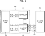
- FIG. 1 schematically illustrates a configuration of a battery pack charging system according to an embodiment of the present disclosure.
- a battery pack charging system may include a charging device 200 and a vehicle 100.
- the vehicle 100 may include a controller 110, a battery pack 120, and a charging port 130.
- the charging device 200 may be one of various devices for charging the battery pack 120 by supplying electric power to the battery pack 120 of the vehicle 100.
- the charging device 200 may receive electric power from a power source and supply the received electric power to the battery pack 120.
- the charging device 200 may receive electric power from an AC power source such as a system power source and supply the received electric power to the battery pack 120.
- an AC power source such as a system power source
- this is exemplary, and the present disclosure is not limited thereto.
- the charging device 200 may receive a signal (a first signal that is described below) including information about a state of charge of the battery pack 120, from the battery pack 120, and determine a charge condition of the battery pack 120 corresponding to the information. For example, the charging device 200 may receive from the battery pack 120 a signal indicating that the battery pack 120 is completely charged, and accordingly discontinue the supply of electric power to the battery pack 120. Furthermore, the charging device 200 may receive from the battery pack 120 a signal indicating that the battery pack 120 needs pre-charge, and accordingly supply current and/or power corresponding to the pre-charge to the battery pack 120.
- a signal (a first signal that is described below) including information about a state of charge of the battery pack 120
- the charging device 200 may receive from the battery pack 120 a signal indicating that the battery pack 120 is completely charged, and accordingly discontinue the supply of electric power to the battery pack 120.
- the charging device 200 may receive from the battery pack 120 a signal indicating that the battery pack 120 needs pre-charge, and accordingly supply current and/or power corresponding
- the charging device 200 may transmit a signal (a second signal described below) including information about one or more states of the charging device 200, to the battery pack 120.
- the charging device 200 may transmit a signal indicating that the vehicle 100 and the charging device 200 are currently connected to each other, to the battery pack 120.
- the charging device 200 may transmit a signal including current charging current and/or voltage to the battery pack 120.
- the charging device 200 may include a communication unit (not shown), a second controller (not shown), and a memory (not shown).
- the communication unit of the charging device 200 may be a device including hardware and software needed for transceiving a control signal through a wired/wireless connection to a device such as the controller 110 and/or the battery pack 120 of the vehicle 100.
- the second controller of the charging device 200 may include all types of devices, such as a processor, capable of processing data.
- a processor may mean, for example, a data processing device embedded in hardware and having a physically structured circuit to perform a function realized by codes or commands included in a program.
- an example of the data processing device embedded in hardware may include a processor such as a microprocessor, a central processing unit (CPU), a processor core, a multiprocessor, a application-specific integrated circuit (ASIC), or a field programmable gate array (FPGA), but the present disclosure is not limited thereto.
- the memory of the charging device 200 may perform a function of temporarily or permanently storing data that is processed by the charging device 200.
- the memory may include a magnetic storage media or a flash storage media, but the present disclosure is not limited thereto.
- the charging device 200 may include a charge interface 210 connected to the charging port 130 of the vehicle 100.
- the charge interface 210 may include ports P+_D and P-_D for supplying electric power, a port P1_D for receiving the first signal, and a port P2_D for transmitting the second signal.
- the ports P+_D and P-_D for supplying electric power may be connected to power ports P+_P2 and P-_P2 of the charging port 130.
- the port P1_D for receiving the first signal may be connected to a port P1_P2 for transmitting the first signal of the charging port 130.
- the port P2_D for transmitting the second signal may be connected to a port P2_P2 for transmitting the first signal of the charging port 130.
- a port A and a port B are connected to each other may signify that the port A and the port B are electrically connected to each other.
- the vehicle 100 may be a vehicle driven by using electricity.
- the vehicle 100 may be a car that is driven by receiving electric power from the battery pack 120 that is charged and driving a motor.
- the vehicle 100 may be a hybrid car driven by a motor that receives electric power from the battery pack 120, or by an internal combustion engine that is driven by using fuel, according to a condition.
- the vehicle 100 according to the present disclosure may mean all vehicles that are driven by using electric power of a battery pack at at least a moment.
- the vehicle 100 may include, as described above, the controller 110, the battery pack 120, and the charging port 130.
- the controller 110 may include all types of devices capable of processing data like a processor that performs driving control, drive control, and charge control of the vehicle 100.
- a processor may mean, for example, a data processing device embedded in hardware and having a physically structured circuit to perform a function realized by codes or commands included in a program.
- an example of the data processing device embedded in hardware may include a processor such as a microprocessor, a CPU, a processor core, a multiprocessor, an ASIC, or a FPGA, but the present disclosure is not limited thereto.
- the controller 110 may receive a signal (second signal) including information about one or more states of the charging device 200 from the charging device 200, and transmit the received signal to the battery pack 120, as part of the charge control.
- the controller 110 may convert the second signal according to a controller area network (CAN) communication protocol, and transmit a converted second signal to the battery pack 120.
- CAN controller area network
- a port P2_C1 for receiving the second signal of the controller 110 and a port P2_P3 for transmitting the second signal of the charging port 130 may be connected to each other.
- the controller 110 may be connected to the battery pack 120 according to a CAN network protocol.
- CAN H ports a port P2_C2 of the controller 110 and a port P2_B1 of the battery pack 120
- CAN L ports a port P2_C3 of the controller 110 and a port P2_B2 of the battery pack 120
- a signal including the state information of the charging device 200 may be transmitted to both of the controller 110 and the battery pack 120. Furthermore, since the controller 110 according to an embodiment of the present disclosure converts the second signal according to the CAN communication protocol and transmits the converted signal to the battery pack 120, the second signal may be shared without signification modification of the battery pack 120 and/or the controller 110.
- the battery pack 120 is a portion for storing electric power and may include a rechargeable unit battery.
- a unit battery may include, for example, a lithium-ion battery or a lithium polymer battery, but the present disclosure is not limited thereto.
- the battery pack 120 may include one or more unit batteries.
- the battery pack 120 may include one unit battery or a plurality of unit batteries.
- the unit batteries may be connected to each other in series, in parallel, or by a combination of serial and parallel connections.
- the number and connection type of the unit batteries included in the battery pack 120 may be determined depending on desired output voltage and electric power storage capacity.
- the battery pack 120 may include a battery management module for managing the above-described unit battery.
- the battery management module may determine whether one or more unit batteries work well and perform various operations according to a result of the determination.
- the battery management module may perform an overcharge protection function, an overdischarge protection function, an overcurrent protection function, an overvoltage protection function, an overheat protection function, or a cell balancing function. Furthermore, the battery management module may determine whether one or more unit batteries work well by checking a current, a voltage, a temperature, a remaining electric power amount, life, or a state of charge (SOC) of the unit batteries. For example, the battery management module may measure cell voltages and temperatures of one or more unit batteries by using sensors.
- SOC state of charge
- the battery management module may include all types of devices capable of processing data like a processor. Since the processor is described above, a description thereof is omitted.
- the battery management module may generate the first signal based on the state of charge of one or more unit batteries and transmit the generated signal to the charging device 200.
- the first signal may be a signal including information about the state of charge of the battery pack 120, as described above.
- the battery management module may generate the first signal in various methods.
- the battery management module may generate the first signal based on the state of charge of one or more unit batteries by a pulse width modulation (PWM).
- PWM pulse width modulation
- FIG. 2 illustrates an example of the first signal generated by the PWM method in the battery pack 120 according to an embodiment of the present disclosure.
- the battery pack 120 may generate a first signal based on a first waveform when the battery pack 120 is in a full state of charge. Similarly, the battery pack 120 may generate a first signal based on a second waveform, which is different from the first waveform, when the battery pack 120 is in a non-chargeable state.
- the battery pack 120 may generate a first signal based on a third waveform when the battery pack 120 is in a first state of charge, and generate a first signal based on a fourth waveform, which is different from the third waveform, when the battery pack 120 is in a second state of charge.
- the above-described first state of charge may be a state in which the battery pack 120 is chargeable with a first current (for example, a state needing pre charge), and the second state of charge may be a state in which the battery pack 120 is chargeable with a second current (for example, a state needing normal charge).
- the second current may be greater than or equal to the first current.
- the charging device 200 may check the state of the battery pack 120.
- waveforms are exemplary, and thus the present disclosure is not limited thereto.
- the types and specific forms of waveforms may vary according to a variety of pieces of information to be transmitted by the battery pack 120 to the charging device 200.
- the battery pack 120 may be electrically connected to the charging port 130.
- the charging port 130 may be electrically connected to the charging device 200 to transmit the first signal.
- a port P1_B for transmitting the first signal of the battery pack 120 may be connected to a port P1_P1 for transmitting the first signal of the charging port 130, and the port P1_P2 for transmitting the first signal of the charging port 130 may be connected to the port P1_D for receiving the first signal of the charging device 200.
- FIG. 3 is a block diagram illustrating a process in which a second signal is transmitted from the charging device 200 to the battery pack 120, according to an embodiment of the present disclosure.
- the charging device 200 may transmit a signal (second signal) including information about one or more states of the charging device 200 to the battery pack 120.
- the port P2_D for transmitting the second signal of the charging device 200 may be connected to the port P2_P2 for transmitting the first signal of the charging port 130.
- the port P2_P3 for transmitting the second signal of the charging port 130 and the port P2_C1 for receiving the second signal of the controller 110 may be connected to each other.
- the CAN H ports (the port P2_C2 of the controller 110 and the port P2_B1 of the battery pack 120) and the CAN L ports (the port P2_C3 of the controller 110 and the port P2_B2 of the battery pack 120) of the controller 110 and the battery pack 120 may be connected to each other.
- the second signal that is generated by the charging device 200 based on the information about one or more states of the charging device 200 may be transmitted to the battery pack 120 along a path 310 from the charging device 200 to the battery pack 120 via the charging port 130, the controller 110.
- the battery pack charging system may transmit the signal including information about the state of the charging device 200 to both of the controller 110 and the battery pack 120. Furthermore, as the controller 110 according to an embodiment of the present disclosure transmit the second signal to the battery pack 120 by converting the second signal according to the CAN communication protocol, the second signal may be shared without signification modification of the battery pack 120 and/or the controller 110.
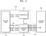
- FIG. 4 is a block diagram illustrating a process in which the first signal is transmitted from the battery pack 120 to the charging device 200, according to an embodiment of the present disclosure.
- the battery pack 120 may generate the first signal based on the state of charge of the battery pack 120 by the PWM method.
- the battery pack 120 may generate a first signal based on a first waveform when the battery pack 120 is in a full state of charge.
- the battery pack 120 may generate a first signal based on a second waveform, which is different from the first waveform, when the battery pack 120 is in a non-chargeable state.
- the battery pack 120 may generate a first signal based on a third waveform when the battery pack 120 is in a first state of charge, and generate a first signal based on a fourth waveform, which is different from the third waveform, when the battery pack 120 is in a second state of charge.
- the above-described first state of charge may be a state in which the battery pack 120 is chargeable with a first current (for example, a state needing pre charge)
- the second state of charge may be a state in which the battery pack 120 is chargeable with a second current (for example, a state needing normal charge).
- the second current may be greater than or equal to the first current.
- the charging device 200 may check the state of the battery pack 120.
- waveforms are exemplary, and thus the present disclosure is not limited thereto.
- the types and specific forms of waveforms may vary according to a variety of pieces of information to be transmitted by the battery pack 120 to the charging device 200.
- the battery pack 120 may be electrically connected to the charging port 130.
- the charging port 130 may be electrically connected to the charging device 200 to transmit the first signal.
- the port P1_B for transmitting the first signal of the battery pack 120 may be connected to the port P1_P1 for transmitting the first signal of the charging port 130
- the port P1_P2 for transmitting the first signal of the charging port 130 may be connected to the port P1_D for receiving the first signal of the charging device 200.
- the first signal that is generated by the battery pack 120 based on the state of charge of the battery pack 120 may be transmitted to the charging device 200 along a path 320 from the battery pack 120 to the charging device 200 via the charging port 130.
- the battery pack 120 may transmit the state of charge to the charging device 200, and thus appropriately control the charging device 200 for charging the battery pack 120.
Landscapes
- Engineering & Computer Science (AREA)
- Power Engineering (AREA)
- Mechanical Engineering (AREA)
- Transportation (AREA)
- Chemical Kinetics & Catalysis (AREA)
- Chemical & Material Sciences (AREA)
- Electrochemistry (AREA)
- General Chemical & Material Sciences (AREA)
- Sustainable Energy (AREA)
- Sustainable Development (AREA)
- Life Sciences & Earth Sciences (AREA)
- Manufacturing & Machinery (AREA)
- Aviation & Aerospace Engineering (AREA)
- Microelectronics & Electronic Packaging (AREA)
- Charge And Discharge Circuits For Batteries Or The Like (AREA)
Abstract
Description
- The present disclosure relates to a battery pack charging system.
- With the development of electrical energy storage technologies, the types of battery packs installed in mobile devices have gradually diversified.
- However, in order to apply a new battery pack to existing wireless devices, related parts of a wireless device and/or charging devices need to be significantly modified.
- In particular, in wireless devices using lead-acid battery packs, significant modification of the wireless devices is required to replace existing lead-acid battery packs with lithium-ion battery packs.
- Provided is a battery pack charging system which enables use of a lithium-ion battery pack without signification modification of related parts of a wireless device and/or a charging device in a system using an existing lead-acid battery pack.
- Also, provided is a battery pack charging system in which a signal including state information of a charging device may be shared by both of a controller of a wireless device and a battery pack.
- According to an aspect of the present disclosure, a battery pack charging system includes a charging device configured to receive a first signal from a battery pack and determine a charge condition of the battery pack based on the first signal, the battery pack configured to generate the first signal based on a state of charge of the battery pack and transmit the first signal to the charging device, and a controller configured to receive a second signal from the charging device and transmit the second signal to the battery pack.
- The battery pack may generate the first signal based on the state of charge of the battery pack by a pulse width modulation (PWM) method.
- The battery pack may generate the first signal based on a first waveform when the battery pack is in a full state of charge, and generate the first signal based on a second waveform when the battery pack is in a non-chargeable state, the second waveform being different from the first waveform.
- When the battery pack is in a first state of charge, the battery pack may generate the first signal based on a third waveform, and when the battery pack is in a second state of charge, the battery pack may generate the first signal based on a fourth waveform, the fourth waveform being different from the third waveform.
- The first state of charge may be a state in which the battery pack is chargeable with a first current, the second state of charge may be a state in which the battery pack is chargeable with a second current, and the second current may be greater than or equal to the first current.
- The controller may be provided in a vehicle, the battery pack may be provided in the vehicle and is further configured to supply electrical energy to the vehicle, and the charging device may be provided separately from the vehicle.
- The controller may convert the second signal received from the charging device according to a controller area network (CAN) communication protocol, and transmit the converted second signal to the battery pack.
- The vehicle may include a charging port that electrically connects the charging device to the vehicle, and the charging port may include a first port that electrically connects the battery pack to the charging device, and a second port that electrically connects the controller to the charging device.
- The battery pack may transmit the first signal to the charging device through the first port, and the controller may receive the second signal from the charging device through the second port.
- The second signal may include information about one or more states of the charging device.
- According to various embodiments of the present disclosure, in a system using an existing lead-acid battery pack, a battery pack charging system capable of using a lithium-ion battery pack without significant modification of related parts of a wireless device and/or a charging device may be implemented.
- Furthermore, a battery pack charging system, in which a signal including state information of a charging device may be shared by both of a controller of a wireless device and a battery pack, may be implemented.
-
-
FIG. 1 schematically illustrates a configuration of a battery pack charging system according to an embodiment of the present disclosure. -
FIG. 2 illustrates an example of a first signal generated by a PWM method in a battery pack, according to an embodiment of the present disclosure. -
FIG. 3 is a block diagram illustrating a process in which a second signal is transmitted from a charging device to a battery pack, according to an embodiment of the present disclosure. -
FIG. 4 is a block diagram illustrating a process in which a first signal is transmitted from a battery pack to a charging device, according to an embodiment of the present disclosure. - According to an aspect of the present disclosure, a battery pack charging system includes a charging device configured to receive a first signal from a battery pack and determine a charge condition of the battery pack based on the first signal, a battery pack configured to generate the first signal based on a state of charge of the battery pack and transmit the first signal to the charging device, and a controller configured to receive a second signal from the charging device and transmit the second signal to the battery pack.
- As the disclosure allows for various changes and numerous embodiments, embodiments will be illustrated in the drawings and described in detail in the written description. However, this is not intended to limit the present disclosure to particular modes of practice, and it is to be appreciated that all changes, equivalents, and substitutes that do not depart from the spirit and technical scope of the present disclosure are encompassed in the present disclosure. In the description of the present disclosure, certain detailed explanations of the related art are omitted when it is deemed that they may unnecessarily obscure the essence of the disclosure.
- For example, a particular shape, structure, and characteristics in the present specification may be implemented by being changed from one embodiment to another embodiment without deviating from the spirit and scope of the present disclosure. Furthermore, the position and arrangement of individual constituent element in each embodiment may be understood to be modified without deviating from the spirit and scope of the present disclosure. Accordingly, the below-described detailed description may not be interpreted to be a limiting meaning, and the scope of the present disclosure may be interpreted to comprehend the scope claimed by the claims and all scopes equivalent thereto. In the drawings, similar reference numerals denote the same or similar elements in various aspects. In other words, described particular items are simple examples. Particular implementations may be changed from such exemplary detailed items, and may be continuously considered within the spirit and scope of the present disclosure.
- Terms such as "first" and "second" are used herein merely to describe a variety of constituent elements, but the constituent elements are not limited by the terms. Such terms are used only for the purpose of distinguishing one constituent element from another constituent element.
- Terms used in the present specification are used for explaining a specific embodiment, not for limiting the present disclosure. Thus, an expression used in a singular form in the present specification also includes the expression in its plural form unless clearly specified otherwise in context. Also, terms such as "include" or "comprise" may be construed to denote a certain characteristic, number, step, operation, constituent element, or a combination thereof, but may not be construed to exclude the existence of or a possibility of addition of one or more other characteristics, numbers, steps, operations, constituent elements, or combinations thereof. Terms such as "first" and "second" are used herein merely to describe a variety of constituent elements, but the constituent elements are not limited by the terms. Such terms are used only for the purpose of distinguishing one constituent element from another constituent element.
- Hereinafter, the present disclosure will be described in detail by explaining embodiments of the disclosure with reference to the attached drawings. Like reference numerals in the drawings denote like elements. Redundant descriptions thereof are omitted.
-
FIG. 1 schematically illustrates a configuration of a battery pack charging system according to an embodiment of the present disclosure. - Referring to
FIG. 1 , a battery pack charging system according to an embodiment of the present disclosure may include acharging device 200 and avehicle 100. Thevehicle 100 may include acontroller 110, abattery pack 120, and acharging port 130. - The
charging device 200 according to an embodiment of the present disclosure may be one of various devices for charging thebattery pack 120 by supplying electric power to thebattery pack 120 of thevehicle 100. - The
charging device 200 according to an embodiment of the present disclosure may receive electric power from a power source and supply the received electric power to thebattery pack 120. For example, thecharging device 200 may receive electric power from an AC power source such as a system power source and supply the received electric power to thebattery pack 120. However, this is exemplary, and the present disclosure is not limited thereto. - The
charging device 200 according to an embodiment of the present disclosure may receive a signal (a first signal that is described below) including information about a state of charge of thebattery pack 120, from thebattery pack 120, and determine a charge condition of thebattery pack 120 corresponding to the information. For example, thecharging device 200 may receive from the battery pack 120 a signal indicating that thebattery pack 120 is completely charged, and accordingly discontinue the supply of electric power to thebattery pack 120. Furthermore, thecharging device 200 may receive from the battery pack 120 a signal indicating that thebattery pack 120 needs pre-charge, and accordingly supply current and/or power corresponding to the pre-charge to thebattery pack 120. - The
charging device 200 according to an embodiment of the present disclosure may transmit a signal (a second signal described below) including information about one or more states of thecharging device 200, to thebattery pack 120. For example, thecharging device 200 may transmit a signal indicating that thevehicle 100 and thecharging device 200 are currently connected to each other, to thebattery pack 120. Furthermore, thecharging device 200 may transmit a signal including current charging current and/or voltage to thebattery pack 120. To this end, thecharging device 200 according to an embodiment of the present disclosure may include a communication unit (not shown), a second controller (not shown), and a memory (not shown). - The communication unit of the
charging device 200 according to an embodiment of the present disclosure may be a device including hardware and software needed for transceiving a control signal through a wired/wireless connection to a device such as thecontroller 110 and/or thebattery pack 120 of thevehicle 100. - The second controller of the
charging device 200 according to an embodiment of the present disclosure may include all types of devices, such as a processor, capable of processing data. A processor may mean, for example, a data processing device embedded in hardware and having a physically structured circuit to perform a function realized by codes or commands included in a program. As such, an example of the data processing device embedded in hardware may include a processor such as a microprocessor, a central processing unit (CPU), a processor core, a multiprocessor, a application-specific integrated circuit (ASIC), or a field programmable gate array (FPGA), but the present disclosure is not limited thereto. - The memory of the
charging device 200 according to an embodiment of the present disclosure may perform a function of temporarily or permanently storing data that is processed by the chargingdevice 200. The memory may include a magnetic storage media or a flash storage media, but the present disclosure is not limited thereto. - The charging
device 200 according to an embodiment of the present disclosure may include acharge interface 210 connected to the chargingport 130 of thevehicle 100. Thecharge interface 210 may include ports P+_D and P-_D for supplying electric power, a port P1_D for receiving the first signal, and a port P2_D for transmitting the second signal. The ports P+_D and P-_D for supplying electric power may be connected to power ports P+_P2 and P-_P2 of the chargingport 130. The port P1_D for receiving the first signal may be connected to a port P1_P2 for transmitting the first signal of the chargingport 130. The port P2_D for transmitting the second signal may be connected to a port P2_P2 for transmitting the first signal of the chargingport 130. - In the present disclosure, "a port A and a port B are connected to each other" may signify that the port A and the port B are electrically connected to each other.
- The
vehicle 100 according to an embodiment of the present disclosure may be a vehicle driven by using electricity. For example, thevehicle 100 may be a car that is driven by receiving electric power from thebattery pack 120 that is charged and driving a motor. Furthermore, thevehicle 100 may be a hybrid car driven by a motor that receives electric power from thebattery pack 120, or by an internal combustion engine that is driven by using fuel, according to a condition. As such, thevehicle 100 according to the present disclosure may mean all vehicles that are driven by using electric power of a battery pack at at least a moment. - The
vehicle 100 according to an embodiment of the present disclosure may include, as described above, thecontroller 110, thebattery pack 120, and the chargingport 130. - First, the
controller 110 according to an embodiment of the present disclosure may include all types of devices capable of processing data like a processor that performs driving control, drive control, and charge control of thevehicle 100. A processor may mean, for example, a data processing device embedded in hardware and having a physically structured circuit to perform a function realized by codes or commands included in a program. As such, an example of the data processing device embedded in hardware may include a processor such as a microprocessor, a CPU, a processor core, a multiprocessor, an ASIC, or a FPGA, but the present disclosure is not limited thereto. - Accordingly, the
controller 110 according to an embodiment may receive a signal (second signal) including information about one or more states of thecharging device 200 from the chargingdevice 200, and transmit the received signal to thebattery pack 120, as part of the charge control. In this regard, thecontroller 110 according to an embodiment of the present disclosure may convert the second signal according to a controller area network (CAN) communication protocol, and transmit a converted second signal to thebattery pack 120. - To this end, according to an embodiment of the present disclosure, a port P2_C1 for receiving the second signal of the
controller 110 and a port P2_P3 for transmitting the second signal of the chargingport 130 may be connected to each other. Furthermore thecontroller 110 according to an embodiment of the present disclosure may be connected to thebattery pack 120 according to a CAN network protocol. In other words, CAN H ports (a port P2_C2 of thecontroller 110 and a port P2_B1 of the battery pack 120) and CAN L ports (a port P2_C3 of thecontroller 110 and a port P2_B2 of the battery pack 120) of thecontroller 110 and thebattery pack 120 may be connected to each other. - Accordingly, in the battery pack charging system according to an embodiment of the present disclosure, a signal including the state information of the
charging device 200 may be transmitted to both of thecontroller 110 and thebattery pack 120. Furthermore, since thecontroller 110 according to an embodiment of the present disclosure converts the second signal according to the CAN communication protocol and transmits the converted signal to thebattery pack 120, the second signal may be shared without signification modification of thebattery pack 120 and/or thecontroller 110. - The
battery pack 120 according to an embodiment of the present disclosure is a portion for storing electric power and may include a rechargeable unit battery. In this regard, a unit battery may include, for example, a lithium-ion battery or a lithium polymer battery, but the present disclosure is not limited thereto. - The
battery pack 120 according to an embodiment of the present disclosure may include one or more unit batteries. In this regard, thebattery pack 120 may include one unit battery or a plurality of unit batteries. In this regard, the unit batteries may be connected to each other in series, in parallel, or by a combination of serial and parallel connections. The number and connection type of the unit batteries included in thebattery pack 120 may be determined depending on desired output voltage and electric power storage capacity. - The
battery pack 120 according to an embodiment of the present disclosure may include a battery management module for managing the above-described unit battery. In this regard, the battery management module may determine whether one or more unit batteries work well and perform various operations according to a result of the determination. - The battery management module may perform an overcharge protection function, an overdischarge protection function, an overcurrent protection function, an overvoltage protection function, an overheat protection function, or a cell balancing function. Furthermore, the battery management module may determine whether one or more unit batteries work well by checking a current, a voltage, a temperature, a remaining electric power amount, life, or a state of charge (SOC) of the unit batteries. For example, the battery management module may measure cell voltages and temperatures of one or more unit batteries by using sensors.
- The battery management module according to an embodiment of the present disclosure may include all types of devices capable of processing data like a processor. Since the processor is described above, a description thereof is omitted.
- The battery management module according to an embodiment of the present disclosure may generate the first signal based on the state of charge of one or more unit batteries and transmit the generated signal to the
charging device 200. In this regard, the first signal may be a signal including information about the state of charge of thebattery pack 120, as described above. - The battery management module according to an embodiment of the present disclosure may generate the first signal in various methods. For example, the battery management module according to an embodiment may generate the first signal based on the state of charge of one or more unit batteries by a pulse width modulation (PWM).
-
FIG. 2 illustrates an example of the first signal generated by the PWM method in thebattery pack 120 according to an embodiment of the present disclosure. - The
battery pack 120 according to an embodiment of the present disclosure may generate a first signal based on a first waveform when thebattery pack 120 is in a full state of charge. Similarly, thebattery pack 120 may generate a first signal based on a second waveform, which is different from the first waveform, when thebattery pack 120 is in a non-chargeable state. - Furthermore, the
battery pack 120 according to an embodiment of the present disclosure may generate a first signal based on a third waveform when thebattery pack 120 is in a first state of charge, and generate a first signal based on a fourth waveform, which is different from the third waveform, when thebattery pack 120 is in a second state of charge. - In this regard, the above-described first state of charge may be a state in which the
battery pack 120 is chargeable with a first current (for example, a state needing pre charge), and the second state of charge may be a state in which thebattery pack 120 is chargeable with a second current (for example, a state needing normal charge). The second current may be greater than or equal to the first current. - In other words, as the
battery pack 120 according to an embodiment adjusts the width of a pulse included in the first signal according to the state of thebattery pack 120, the chargingdevice 200 may check the state of thebattery pack 120. - However, the above-described types and specific forms of waveforms are exemplary, and thus the present disclosure is not limited thereto. The types and specific forms of waveforms may vary according to a variety of pieces of information to be transmitted by the
battery pack 120 to thecharging device 200. - To transmit the first signal generated by the above-described method to the
charging device 200, thebattery pack 120 according to an embodiment of the present disclosure may be electrically connected to the chargingport 130. The chargingport 130 may be electrically connected to thecharging device 200 to transmit the first signal. In detail, a port P1_B for transmitting the first signal of thebattery pack 120 may be connected to a port P1_P1 for transmitting the first signal of the chargingport 130, and the port P1_P2 for transmitting the first signal of the chargingport 130 may be connected to the port P1_D for receiving the first signal of thecharging device 200. -
FIG. 3 is a block diagram illustrating a process in which a second signal is transmitted from the chargingdevice 200 to thebattery pack 120, according to an embodiment of the present disclosure. - As described above, the charging
device 200 according to an embodiment of the present disclosure may transmit a signal (second signal) including information about one or more states of thecharging device 200 to thebattery pack 120. Furthermore, the port P2_D for transmitting the second signal of thecharging device 200 may be connected to the port P2_P2 for transmitting the first signal of the chargingport 130. The port P2_P3 for transmitting the second signal of the chargingport 130 and the port P2_C1 for receiving the second signal of thecontroller 110 may be connected to each other. The CAN H ports (the port P2_C2 of thecontroller 110 and the port P2_B1 of the battery pack 120) and the CAN L ports (the port P2_C3 of thecontroller 110 and the port P2_B2 of the battery pack 120) of thecontroller 110 and thebattery pack 120 may be connected to each other. - Accordingly, the second signal that is generated by the charging
device 200 based on the information about one or more states of thecharging device 200 may be transmitted to thebattery pack 120 along apath 310 from the chargingdevice 200 to thebattery pack 120 via the chargingport 130, thecontroller 110. - Accordingly, the battery pack charging system according to an embodiment of the present disclosure may transmit the signal including information about the state of the
charging device 200 to both of thecontroller 110 and thebattery pack 120. Furthermore, as thecontroller 110 according to an embodiment of the present disclosure transmit the second signal to thebattery pack 120 by converting the second signal according to the CAN communication protocol, the second signal may be shared without signification modification of thebattery pack 120 and/or thecontroller 110. -
FIG. 4 is a block diagram illustrating a process in which the first signal is transmitted from thebattery pack 120 to thecharging device 200, according to an embodiment of the present disclosure. - As described above, the
battery pack 120 according to an embodiment may generate the first signal based on the state of charge of thebattery pack 120 by the PWM method. - For example, the
battery pack 120 according to an embodiment of the present disclosure may generate a first signal based on a first waveform when thebattery pack 120 is in a full state of charge. Similarly, thebattery pack 120 may generate a first signal based on a second waveform, which is different from the first waveform, when thebattery pack 120 is in a non-chargeable state. - Furthermore, the
battery pack 120 according to an embodiment of the present disclosure may generate a first signal based on a third waveform when thebattery pack 120 is in a first state of charge, and generate a first signal based on a fourth waveform, which is different from the third waveform, when thebattery pack 120 is in a second state of charge. In this regard, the above-described first state of charge may be a state in which thebattery pack 120 is chargeable with a first current (for example, a state needing pre charge), and the second state of charge may be a state in which thebattery pack 120 is chargeable with a second current (for example, a state needing normal charge). The second current may be greater than or equal to the first current. - In other words, as the
battery pack 120 according to an embodiment adjusts the width of a pulse included in the first signal according to the state of thebattery pack 120, the chargingdevice 200 may check the state of thebattery pack 120. - However, the above-described types and specific forms of waveforms are exemplary, and thus the present disclosure is not limited thereto. The types and specific forms of waveforms may vary according to a variety of pieces of information to be transmitted by the
battery pack 120 to thecharging device 200. - To transmit the first signal generated by the above-described method to the
charging device 200, thebattery pack 120 according to an embodiment of the present disclosure may be electrically connected to the chargingport 130. The chargingport 130 may be electrically connected to thecharging device 200 to transmit the first signal. In detail, the port P1_B for transmitting the first signal of thebattery pack 120 may be connected to the port P1_P1 for transmitting the first signal of the chargingport 130, and the port P1_P2 for transmitting the first signal of the chargingport 130 may be connected to the port P1_D for receiving the first signal of thecharging device 200. - Accordingly, the first signal that is generated by the
battery pack 120 based on the state of charge of thebattery pack 120 may be transmitted to thecharging device 200 along apath 320 from thebattery pack 120 to thecharging device 200 via the chargingport 130. - As such, the
battery pack 120 according to an embodiment of the present disclosure may transmit the state of charge to thecharging device 200, and thus appropriately control thecharging device 200 for charging thebattery pack 120. - While this disclosure has been particularly shown and described with reference to preferred embodiments thereof, it will be understood by those of ordinary skill in the art that various changes in form and details may be made therein without departing from the spirit and scope of the disclosure as defined by the appended claims. The preferred embodiments should be considered in descriptive sense only and not for purposes of limitation. Therefore, the scope of the disclosure is defined not by the detailed description of the disclosure but by the appended claims, and all differences within the scope will be construed as being included in the present disclosure.
Claims (10)
- A battery pack charging system comprising:a charging device configured to receive a first signal from a battery pack and determine a charge condition of the battery pack based on the first signal;the battery pack configured to generate the first signal based on a state of charge of the battery pack and transmit the first signal to the charging device; anda controller configured to receive a second signal from the charging device and transmit the second signal to the battery pack.
- The battery pack charging system of claim 1, wherein the battery pack generates the first signal based on the state of charge of the battery pack by a pulse width modulation (PWM) method.
- The battery pack charging system of claim 2, wherein the battery pack generates the first signal based on a first waveform when the battery pack is in a full state of charge, and generates the first signal based on a second waveform when the battery pack is in a non-chargeable state, the second waveform being different from the first waveform.
- The battery pack charging system of claim 2, wherein, when the battery pack is in a first state of charge, the battery pack generates the first signal based on a third waveform, and when the battery pack is in a second state of charge, the battery pack generates the first signal based on a fourth waveform, the fourth waveform being different from the third waveform.
- The battery pack charging system of claim 4, wherein the first state of charge is a state in which the battery pack is chargeable with a first current,
the second state of charge is a state in which the battery pack is chargeable with a second current, and
the second current is greater than or equal to the first current. - The battery pack charging system of claim 1, wherein the controller is provided in a vehicle,
the battery pack is provided in the vehicle and is further configured to supply electrical energy to the vehicle, and
the charging device is provided separately from the vehicle. - The battery pack charging system of claim 6, wherein the controller converts the second signal received from the charging device according to a controller area network (CAN) communication protocol, and transmits the converted second signal to the battery pack.
- The battery pack charging system of claim 6, wherein the vehicle comprises a charging port that electrically connects the charging device to the vehicle, and
the charging port comprises:a first port that electrically connects the battery pack to the charging device; anda second port that electrically connects the controller to the charging device. - The battery pack charging system of claim 8, wherein the battery pack transmits the first signal to the charging device through the first port, and
the controller receives the second signal from the charging device through the second port. - The battery pack charging system of claim 1, wherein the second signal comprises information about one or more states of the charging device.
Applications Claiming Priority (2)
| Application Number | Priority Date | Filing Date | Title |
|---|---|---|---|
| KR1020160164382A KR102314043B1 (en) | 2016-12-05 | 2016-12-05 | Battery Pack Charging System |
| PCT/KR2017/011360 WO2018105874A1 (en) | 2016-12-05 | 2017-10-16 | Battery pack charging system |
Publications (2)
| Publication Number | Publication Date |
|---|---|
| EP3550694A1 true EP3550694A1 (en) | 2019-10-09 |
| EP3550694A4 EP3550694A4 (en) | 2020-06-10 |
Family
ID=62491604
Family Applications (1)
| Application Number | Title | Priority Date | Filing Date |
|---|---|---|---|
| EP17877898.1A Pending EP3550694A4 (en) | 2016-12-05 | 2017-10-16 | BATTERY PACK CHARGING SYSTEM |
Country Status (5)
| Country | Link |
|---|---|
| US (1) | US12179622B2 (en) |
| EP (1) | EP3550694A4 (en) |
| KR (1) | KR102314043B1 (en) |
| CN (1) | CN109075592B (en) |
| WO (1) | WO2018105874A1 (en) |
Cited By (1)
| Publication number | Priority date | Publication date | Assignee | Title |
|---|---|---|---|---|
| US20220216721A1 (en) * | 2019-09-29 | 2022-07-07 | Autel Intelligent Technology Corp., Ltd. | Control system and method for improving battery output energy efficiency, and electronic device |
Families Citing this family (11)
| Publication number | Priority date | Publication date | Assignee | Title |
|---|---|---|---|---|
| USD1012855S1 (en) | 2019-09-05 | 2024-01-30 | Techtronic Cordless Gp | Battery pack |
| USD929336S1 (en) | 2019-09-05 | 2021-08-31 | Techtronic Cordless Gp | Electrical interface |
| USD929337S1 (en) | 2019-09-05 | 2021-08-31 | Techtronic Cordless Gp | Electrical interface |
| USD929335S1 (en) | 2019-09-05 | 2021-08-31 | Techtronic Cordless Gp | Electrical interface |
| USD953268S1 (en) | 2019-09-05 | 2022-05-31 | Techtronic Cordless Gp | Electrical interface |
| USD929339S1 (en) | 2019-09-05 | 2021-08-31 | Techtronic Cordless Gp | Electrical interface |
| USD929334S1 (en) | 2019-09-05 | 2021-08-31 | Techtronic Cordless Gp | Electrical interface |
| USD929338S1 (en) | 2019-09-05 | 2021-08-31 | Techtronic Cordless Gp | Electrical interface |
| CN110867919B (en) * | 2019-11-21 | 2022-03-25 | 深圳市睿鑫智科技有限公司 | System capable of realizing synchronization of charging signals |
| US20230275444A1 (en) * | 2022-02-25 | 2023-08-31 | Milwaukee Electric Tool Corporation | Magnet coupling assembly |
| US20240092220A1 (en) * | 2022-09-15 | 2024-03-21 | GM Global Technology Operations LLC | Key-off electrical load management for a vehicle |
Family Cites Families (71)
| Publication number | Priority date | Publication date | Assignee | Title |
|---|---|---|---|---|
| US5619117A (en) * | 1982-06-07 | 1997-04-08 | Norand Corporation | Battery pack having memory |
| DE69220228T2 (en) * | 1991-08-01 | 1997-09-25 | Wavedriver Ltd | Battery powered electric vehicle and electrical supply system |
| JPH06343202A (en) * | 1993-06-01 | 1994-12-13 | Nissan Motor Co Ltd | Electric vehicle charging device |
| US6768285B2 (en) | 1995-08-24 | 2004-07-27 | Ellen James | Power system for converting variable source power to constant load power |
| US6087802A (en) * | 1995-08-24 | 2000-07-11 | James; Ellen | Lightweight, compact, on-board electric vehicle battery charger |
| US7059769B1 (en) * | 1997-06-27 | 2006-06-13 | Patrick Henry Potega | Apparatus for enabling multiple modes of operation among a plurality of devices |
| US6459175B1 (en) * | 1997-11-17 | 2002-10-01 | Patrick H. Potega | Universal power supply |
| US6236186B1 (en) * | 1999-12-23 | 2001-05-22 | Intermec Ip | Method and system for discriminating between different types of batteries and charging the same |
| JP2002014749A (en) * | 2000-06-30 | 2002-01-18 | Mitsubishi Electric Corp | Power system |
| JP4207651B2 (en) * | 2003-05-07 | 2009-01-14 | ソニー株式会社 | Charger |
| US7270910B2 (en) * | 2003-10-03 | 2007-09-18 | Black & Decker Inc. | Thermal management systems for battery packs |
| US20070230227A1 (en) * | 2004-04-29 | 2007-10-04 | Palmer Douglas A | Universal Power Adapter |
| US7317297B1 (en) * | 2004-07-15 | 2008-01-08 | National Semiconductor Corporation | Battery temperature sensor pin used as communication channel |
| CN201515238U (en) * | 2004-10-18 | 2010-06-23 | 布莱克和戴克公司 | Cordless power tool system and battery pack for cordless power tool system |
| JP2006302733A (en) * | 2005-04-22 | 2006-11-02 | Matsushita Electric Ind Co Ltd | Battery pack and connection system thereof |
| EP1780867B1 (en) * | 2005-10-28 | 2016-11-30 | Black & Decker Inc. | Battery pack for cordless power tools |
| KR100824905B1 (en) * | 2006-08-24 | 2008-04-23 | 삼성에스디아이 주식회사 | Hybrid battery and its full charge capacity calculation method |
| US7764046B2 (en) * | 2006-08-31 | 2010-07-27 | Semiconductor Energy Laboratory Co., Ltd. | Power storage device and semiconductor device provided with the power storage device |
| US8222870B2 (en) | 2007-03-07 | 2012-07-17 | O2Micro, Inc | Battery management systems with adjustable charging current |
| JP2009247195A (en) | 2008-03-31 | 2009-10-22 | O2 Micro Inc | Battery management system with adjustable charging current |
| US8111038B2 (en) * | 2008-06-12 | 2012-02-07 | O2 Micro, Inc | Vehicle electronic systems with battery management functions |
| CN101714647B (en) * | 2008-10-08 | 2012-11-28 | 株式会社牧田 | Battery pack for power tool, and power tool |
| JP5267050B2 (en) | 2008-10-30 | 2013-08-21 | 株式会社豊田自動織機 | Battery level monitor system |
| KR20110012114A (en) * | 2009-07-29 | 2011-02-09 | 엘지전자 주식회사 | Battery control device and method of the car |
| US8278875B2 (en) * | 2010-05-14 | 2012-10-02 | Coulomb Technologies, Inc. | Safety supervisory module of an electric vehicle charging station |
| KR101245277B1 (en) | 2010-06-08 | 2013-03-19 | 주식회사 엘지화학 | Battery pack charging system and method |
| JP5312504B2 (en) * | 2011-03-29 | 2013-10-09 | 三菱電機株式会社 | Energy management system |
| KR20120136821A (en) | 2011-06-10 | 2012-12-20 | 현대자동차주식회사 | Method for controling starting reset of electric vehicle |
| JP5594239B2 (en) * | 2011-06-27 | 2014-09-24 | 株式会社デンソー | In-vehicle storage battery charging system |
| JP5835152B2 (en) * | 2011-09-16 | 2015-12-24 | 日立金属株式会社 | Vehicle charging device |
| KR101283602B1 (en) | 2011-12-08 | 2013-07-05 | 현대자동차주식회사 | Charging network system for electric vehicle |
| KR101995577B1 (en) * | 2011-12-14 | 2019-07-04 | 한국전자통신연구원 | Device and method for controlling energy of vehicle according to storage state level |
| KR20130068160A (en) * | 2011-12-14 | 2013-06-26 | 한국전자통신연구원 | Structure for energy management system and energy managemant method in electric vehicel |
| US9071074B2 (en) | 2012-02-20 | 2015-06-30 | Eaton Corporation | Multi-standard, alternating current or direct current compatible electric vehicle supply equipment |
| KR101338003B1 (en) * | 2012-03-07 | 2013-12-09 | 한국전기연구원 | Device of power line communication for electric vehicle charging and system for it |
| DE102012203852A1 (en) * | 2012-03-13 | 2013-09-19 | Bayerische Motoren Werke Aktiengesellschaft | Device for charging an energy store of one or more electrically operated vehicles |
| US9466992B2 (en) * | 2012-05-19 | 2016-10-11 | Tesla Motors, Inc. | Method and system for servicing high voltage battery packs |
| JP2014023244A (en) * | 2012-07-17 | 2014-02-03 | Toyota Motor Corp | Power stand |
| EP2907218A4 (en) * | 2012-10-09 | 2016-06-08 | J B Wright | INTELLIGENT DISTRIBUTED BATTERY SYSTEM AND METHOD THEREOF |
| JP2014137890A (en) * | 2013-01-16 | 2014-07-28 | Makita Corp | Charging device |
| US10870360B2 (en) * | 2013-02-12 | 2020-12-22 | Cps Technology Holdings Llc | Battery monitoring network |
| JP5546658B1 (en) * | 2013-03-04 | 2014-07-09 | 三菱電機株式会社 | Electric vehicle |
| US20160036098A1 (en) * | 2013-03-22 | 2016-02-04 | Sony Corporation | Management apparatus, communication apparatus, management method, and management system |
| KR101721517B1 (en) * | 2013-03-26 | 2017-03-30 | 쥬코쿠 덴료쿠 가부시키 가이샤 | Method for controlling charge/discharge system, and charge/discharge system |
| KR102154274B1 (en) * | 2013-03-29 | 2020-09-10 | 주식회사 케이티 | Electric vehicle charging management apparatus and method |
| US20140300311A1 (en) * | 2013-04-08 | 2014-10-09 | Magnadyne Corporation | Portable power bank and battery booster |
| KR101480616B1 (en) | 2013-06-05 | 2015-01-09 | 현대자동차주식회사 | On-board battery charger for electric vehicles and control method thereof |
| CN105263739A (en) * | 2013-06-07 | 2016-01-20 | 株式会社丰田自动织机 | Battery and charging device management system, method, and charging device |
| JP6300006B2 (en) * | 2013-12-19 | 2018-03-28 | カシオ計算機株式会社 | Electronic device and program |
| CN203942309U (en) * | 2014-05-29 | 2014-11-12 | 长城汽车股份有限公司 | Charging system for electric automobile |
| US9573476B2 (en) * | 2014-06-09 | 2017-02-21 | GM Global Technology Operations LLC | Method and apparatus for controller wakeup using control pilot signal from charge port |
| JP2016021845A (en) * | 2014-07-16 | 2016-02-04 | 株式会社 ハセテック | Charger and charge control device |
| AU2015301449B2 (en) * | 2014-08-14 | 2018-07-05 | Schumacher Electric Corp. | Compact multifunctional battery booster |
| KR101821007B1 (en) | 2014-09-01 | 2018-01-22 | 엘에스산전 주식회사 | Recharging device and recharging method for vehicle |
| KR20160072982A (en) * | 2014-12-16 | 2016-06-24 | 현대자동차주식회사 | Method for selecting recharging mode and recharging system for carrying out the same |
| US10389141B2 (en) | 2014-12-19 | 2019-08-20 | California Institute Of Technology | Systems and methods for management and monitoring of energy storage and distribution |
| DE102015206047A1 (en) | 2015-04-02 | 2016-10-06 | Volkswagen Aktiengesellschaft | Adapter for a charging plug system |
| CN104868545A (en) * | 2015-05-22 | 2015-08-26 | 重庆川仪自动化股份有限公司 | Control method of cell charging, control circuit and control system thereof |
| WO2016206648A1 (en) * | 2015-06-26 | 2016-12-29 | 苏州宝时得电动工具有限公司 | Autonomous mobile device and wireless charging system thereof |
| CN113921289B (en) * | 2015-07-31 | 2022-12-02 | 新塞尔斯有限公司 | Power supply system and method for generating output electric signal and authenticating battery pack |
| CN105098900B (en) * | 2015-08-05 | 2018-05-29 | 青岛海信移动通信技术股份有限公司 | Mobile terminal, can directly charge source adapter and charging method |
| CN105098945B (en) * | 2015-08-05 | 2018-01-09 | 青岛海信移动通信技术股份有限公司 | One kind can directly charge source adapter |
| CN104993562B (en) * | 2015-08-05 | 2017-12-05 | 青岛海信移动通信技术股份有限公司 | Can directly be charged source adapter |
| KR101780284B1 (en) * | 2015-10-26 | 2017-10-10 | 현대자동차주식회사 | Method for selecting automatic recharging mode and recharging system for carrying out the same |
| US10093195B2 (en) * | 2015-11-13 | 2018-10-09 | Nio Usa, Inc. | Integrated vehicle charging panel system and method of use |
| US9964415B2 (en) * | 2015-11-13 | 2018-05-08 | Nio Usa, Inc. | Tracking power consumption and payment |
| US20170136893A1 (en) * | 2015-11-13 | 2017-05-18 | NextEv USA, Inc. | Vehicle skin charging system and method |
| US10252631B2 (en) * | 2015-11-13 | 2019-04-09 | Nio Usa, Inc. | Communications between vehicle and charging system |
| CN205265301U (en) * | 2015-12-30 | 2016-05-25 | 江苏绿城信息技术有限公司 | Car stake of charging |
| CN106537724B (en) * | 2016-02-05 | 2020-01-10 | Oppo广东移动通信有限公司 | Charging method, adapter and mobile terminal |
| US20170327002A1 (en) * | 2016-05-11 | 2017-11-16 | Leslie G. Lilly | Pulse modulation for driving an electric vehicle drive and for harvesting energy |
-
2016
- 2016-12-05 KR KR1020160164382A patent/KR102314043B1/en active Active
-
2017
- 2017-10-16 CN CN201780025964.3A patent/CN109075592B/en active Active
- 2017-10-16 EP EP17877898.1A patent/EP3550694A4/en active Pending
- 2017-10-16 US US16/079,723 patent/US12179622B2/en active Active
- 2017-10-16 WO PCT/KR2017/011360 patent/WO2018105874A1/en not_active Ceased
Cited By (2)
| Publication number | Priority date | Publication date | Assignee | Title |
|---|---|---|---|---|
| US20220216721A1 (en) * | 2019-09-29 | 2022-07-07 | Autel Intelligent Technology Corp., Ltd. | Control system and method for improving battery output energy efficiency, and electronic device |
| US12451716B2 (en) * | 2019-09-29 | 2025-10-21 | Autel Intelligent Technology Corp., Ltd. | Control system and method for improving battery output energy efficiency, and electronic device |
Also Published As
| Publication number | Publication date |
|---|---|
| CN109075592B (en) | 2023-03-28 |
| US20190061652A1 (en) | 2019-02-28 |
| WO2018105874A1 (en) | 2018-06-14 |
| KR102314043B1 (en) | 2021-10-18 |
| EP3550694A4 (en) | 2020-06-10 |
| CN109075592A (en) | 2018-12-21 |
| US12179622B2 (en) | 2024-12-31 |
| KR20180064131A (en) | 2018-06-14 |
Similar Documents
| Publication | Publication Date | Title |
|---|---|---|
| US12179622B2 (en) | Battery pack charging system | |
| CN105703447B (en) | Direct Balance Charging Method for Rechargeable Batteries | |
| US12401203B2 (en) | Charging method, battery management system of traction battery and charging pile | |
| US8264201B2 (en) | Battery management system and driving method thereof | |
| EP3739720A1 (en) | Battery control method and apparatus, battery module, and battery pack | |
| EP2645527A1 (en) | Battery pack | |
| EP2793309B1 (en) | System for automatically recognizing battery characteristic, battery information storage device for the same, and method for automatically optimizing battery management device by using the same | |
| US20100121511A1 (en) | Li-ion battery array for vehicle and other large capacity applications | |
| US20120169117A1 (en) | Battery system and electric vehicle including the same | |
| CN102738847B (en) | Charging module and rechargeable battery combination for electric vehicles | |
| EP3339086A1 (en) | Motor vehicle and charge and discharge control circuit thereof | |
| CN116325286B (en) | Charging and discharging device, battery charging method and charging and discharging system | |
| KR102783740B1 (en) | Portable electric vehicle battery charger | |
| CN205565813U (en) | Rechargeable battery group directly balances charging device | |
| KR101741303B1 (en) | Voltage balancing apparatus and method between battery racks | |
| KR20240157923A (en) | Battery pack, charging method thereof, and electric vehicle having the same | |
| EP3576211A1 (en) | Method and system for managing battery pack | |
| KR101472886B1 (en) | Device for Voltage Balancing of Battery Pack and Balancing Process Using the Same | |
| CN207166171U (en) | A kind of battery charge controller of lithium battery pack | |
| US20210111438A1 (en) | Battery unit for a vehicle with a separate communication unit | |
| KR102759864B1 (en) | Hybrid Balancing Battery Management System, Battery Pack and EV including the same | |
| CN109326838A (en) | Battery all standing safety monitoring system and battery management method | |
| Hnatova et al. | Вattery management system | |
| KR20150051494A (en) | Battery system for rapid charging | |
| ES2938792A1 (en) | RECHARGEABLE BATTERY MANAGEMENT SYSTEM FOR BATTERY PACKS FOR ELECTRIC VEHICLES (Machine-translation by Google Translate, not legally binding) |
Legal Events
| Date | Code | Title | Description |
|---|---|---|---|
| STAA | Information on the status of an ep patent application or granted ep patent |
Free format text: STATUS: THE INTERNATIONAL PUBLICATION HAS BEEN MADE |
|
| PUAI | Public reference made under article 153(3) epc to a published international application that has entered the european phase |
Free format text: ORIGINAL CODE: 0009012 |
|
| STAA | Information on the status of an ep patent application or granted ep patent |
Free format text: STATUS: REQUEST FOR EXAMINATION WAS MADE |
|
| 17P | Request for examination filed |
Effective date: 20190605 |
|
| AK | Designated contracting states |
Kind code of ref document: A1 Designated state(s): AL AT BE BG CH CY CZ DE DK EE ES FI FR GB GR HR HU IE IS IT LI LT LU LV MC MK MT NL NO PL PT RO RS SE SI SK SM TR |
|
| AX | Request for extension of the european patent |
Extension state: BA ME |
|
| DAV | Request for validation of the european patent (deleted) | ||
| DAX | Request for extension of the european patent (deleted) | ||
| A4 | Supplementary search report drawn up and despatched |
Effective date: 20200513 |
|
| RIC1 | Information provided on ipc code assigned before grant |
Ipc: B60L 58/12 20190101ALI20200507BHEP Ipc: B60R 16/03 20060101ALI20200507BHEP Ipc: H01M 10/42 20060101ALN20200507BHEP Ipc: H01M 10/44 20060101ALI20200507BHEP Ipc: H01M 2/10 20060101ALI20200507BHEP Ipc: B60L 53/66 20190101ALI20200507BHEP Ipc: B60L 53/62 20190101ALI20200507BHEP Ipc: H02J 7/00 20060101AFI20200507BHEP |
|
| STAA | Information on the status of an ep patent application or granted ep patent |
Free format text: STATUS: EXAMINATION IS IN PROGRESS |
|
| 17Q | First examination report despatched |
Effective date: 20230224 |