EP3550163B1 - Sliding member - Google Patents
Sliding member Download PDFInfo
- Publication number
- EP3550163B1 EP3550163B1 EP19162305.7A EP19162305A EP3550163B1 EP 3550163 B1 EP3550163 B1 EP 3550163B1 EP 19162305 A EP19162305 A EP 19162305A EP 3550163 B1 EP3550163 B1 EP 3550163B1
- Authority
- EP
- European Patent Office
- Prior art keywords
- metal layer
- mass
- layer
- copper alloy
- ferrite phase
- Prior art date
- Legal status (The legal status is an assumption and is not a legal conclusion. Google has not performed a legal analysis and makes no representation as to the accuracy of the status listed.)
- Revoked
Links
Images
Classifications
-
- F—MECHANICAL ENGINEERING; LIGHTING; HEATING; WEAPONS; BLASTING
- F16—ENGINEERING ELEMENTS AND UNITS; GENERAL MEASURES FOR PRODUCING AND MAINTAINING EFFECTIVE FUNCTIONING OF MACHINES OR INSTALLATIONS; THERMAL INSULATION IN GENERAL
- F16C—SHAFTS; FLEXIBLE SHAFTS; ELEMENTS OR CRANKSHAFT MECHANISMS; ROTARY BODIES OTHER THAN GEARING ELEMENTS; BEARINGS
- F16C33/00—Parts of bearings; Special methods for making bearings or parts thereof
- F16C33/02—Parts of sliding-contact bearings
- F16C33/04—Brasses; Bushes; Linings
- F16C33/043—Sliding surface consisting mainly of ceramics, cermets or hard carbon, e.g. diamond like carbon [DLC]
-
- F—MECHANICAL ENGINEERING; LIGHTING; HEATING; WEAPONS; BLASTING
- F16—ENGINEERING ELEMENTS AND UNITS; GENERAL MEASURES FOR PRODUCING AND MAINTAINING EFFECTIVE FUNCTIONING OF MACHINES OR INSTALLATIONS; THERMAL INSULATION IN GENERAL
- F16C—SHAFTS; FLEXIBLE SHAFTS; ELEMENTS OR CRANKSHAFT MECHANISMS; ROTARY BODIES OTHER THAN GEARING ELEMENTS; BEARINGS
- F16C33/00—Parts of bearings; Special methods for making bearings or parts thereof
- F16C33/02—Parts of sliding-contact bearings
- F16C33/04—Brasses; Bushes; Linings
- F16C33/06—Sliding surface mainly made of metal
- F16C33/14—Special methods of manufacture; Running-in
-
- C—CHEMISTRY; METALLURGY
- C22—METALLURGY; FERROUS OR NON-FERROUS ALLOYS; TREATMENT OF ALLOYS OR NON-FERROUS METALS
- C22C—ALLOYS
- C22C32/00—Non-ferrous alloys containing at least 5% by weight but less than 50% by weight of oxides, carbides, borides, nitrides, silicides or other metal compounds, e.g. oxynitrides, sulfides, whether added as such or formed in situ
-
- C—CHEMISTRY; METALLURGY
- C22—METALLURGY; FERROUS OR NON-FERROUS ALLOYS; TREATMENT OF ALLOYS OR NON-FERROUS METALS
- C22C—ALLOYS
- C22C38/00—Ferrous alloys, e.g. steel alloys
- C22C38/02—Ferrous alloys, e.g. steel alloys containing silicon
-
- C—CHEMISTRY; METALLURGY
- C22—METALLURGY; FERROUS OR NON-FERROUS ALLOYS; TREATMENT OF ALLOYS OR NON-FERROUS METALS
- C22C—ALLOYS
- C22C38/00—Ferrous alloys, e.g. steel alloys
- C22C38/04—Ferrous alloys, e.g. steel alloys containing manganese
-
- C—CHEMISTRY; METALLURGY
- C22—METALLURGY; FERROUS OR NON-FERROUS ALLOYS; TREATMENT OF ALLOYS OR NON-FERROUS METALS
- C22C—ALLOYS
- C22C38/00—Ferrous alloys, e.g. steel alloys
- C22C38/60—Ferrous alloys, e.g. steel alloys containing lead, selenium, tellurium, or antimony, or more than 0.04% by weight of sulfur
-
- C—CHEMISTRY; METALLURGY
- C22—METALLURGY; FERROUS OR NON-FERROUS ALLOYS; TREATMENT OF ALLOYS OR NON-FERROUS METALS
- C22C—ALLOYS
- C22C9/00—Alloys based on copper
-
- C—CHEMISTRY; METALLURGY
- C22—METALLURGY; FERROUS OR NON-FERROUS ALLOYS; TREATMENT OF ALLOYS OR NON-FERROUS METALS
- C22C—ALLOYS
- C22C9/00—Alloys based on copper
- C22C9/01—Alloys based on copper with aluminium as the next major constituent
-
- C—CHEMISTRY; METALLURGY
- C22—METALLURGY; FERROUS OR NON-FERROUS ALLOYS; TREATMENT OF ALLOYS OR NON-FERROUS METALS
- C22C—ALLOYS
- C22C9/00—Alloys based on copper
- C22C9/02—Alloys based on copper with tin as the next major constituent
-
- C—CHEMISTRY; METALLURGY
- C22—METALLURGY; FERROUS OR NON-FERROUS ALLOYS; TREATMENT OF ALLOYS OR NON-FERROUS METALS
- C22C—ALLOYS
- C22C9/00—Alloys based on copper
- C22C9/04—Alloys based on copper with zinc as the next major constituent
-
- C—CHEMISTRY; METALLURGY
- C22—METALLURGY; FERROUS OR NON-FERROUS ALLOYS; TREATMENT OF ALLOYS OR NON-FERROUS METALS
- C22C—ALLOYS
- C22C9/00—Alloys based on copper
- C22C9/05—Alloys based on copper with manganese as the next major constituent
-
- C—CHEMISTRY; METALLURGY
- C22—METALLURGY; FERROUS OR NON-FERROUS ALLOYS; TREATMENT OF ALLOYS OR NON-FERROUS METALS
- C22C—ALLOYS
- C22C9/00—Alloys based on copper
- C22C9/06—Alloys based on copper with nickel or cobalt as the next major constituent
-
- C—CHEMISTRY; METALLURGY
- C22—METALLURGY; FERROUS OR NON-FERROUS ALLOYS; TREATMENT OF ALLOYS OR NON-FERROUS METALS
- C22C—ALLOYS
- C22C9/00—Alloys based on copper
- C22C9/08—Alloys based on copper with lead as the next major constituent
-
- C—CHEMISTRY; METALLURGY
- C22—METALLURGY; FERROUS OR NON-FERROUS ALLOYS; TREATMENT OF ALLOYS OR NON-FERROUS METALS
- C22C—ALLOYS
- C22C9/00—Alloys based on copper
- C22C9/10—Alloys based on copper with silicon as the next major constituent
-
- F—MECHANICAL ENGINEERING; LIGHTING; HEATING; WEAPONS; BLASTING
- F16—ENGINEERING ELEMENTS AND UNITS; GENERAL MEASURES FOR PRODUCING AND MAINTAINING EFFECTIVE FUNCTIONING OF MACHINES OR INSTALLATIONS; THERMAL INSULATION IN GENERAL
- F16C—SHAFTS; FLEXIBLE SHAFTS; ELEMENTS OR CRANKSHAFT MECHANISMS; ROTARY BODIES OTHER THAN GEARING ELEMENTS; BEARINGS
- F16C17/00—Sliding-contact bearings for exclusively rotary movement
- F16C17/02—Sliding-contact bearings for exclusively rotary movement for radial load only
-
- F—MECHANICAL ENGINEERING; LIGHTING; HEATING; WEAPONS; BLASTING
- F16—ENGINEERING ELEMENTS AND UNITS; GENERAL MEASURES FOR PRODUCING AND MAINTAINING EFFECTIVE FUNCTIONING OF MACHINES OR INSTALLATIONS; THERMAL INSULATION IN GENERAL
- F16C—SHAFTS; FLEXIBLE SHAFTS; ELEMENTS OR CRANKSHAFT MECHANISMS; ROTARY BODIES OTHER THAN GEARING ELEMENTS; BEARINGS
- F16C33/00—Parts of bearings; Special methods for making bearings or parts thereof
- F16C33/02—Parts of sliding-contact bearings
- F16C33/04—Brasses; Bushes; Linings
- F16C33/06—Sliding surface mainly made of metal
- F16C33/10—Construction relative to lubrication
-
- F—MECHANICAL ENGINEERING; LIGHTING; HEATING; WEAPONS; BLASTING
- F16—ENGINEERING ELEMENTS AND UNITS; GENERAL MEASURES FOR PRODUCING AND MAINTAINING EFFECTIVE FUNCTIONING OF MACHINES OR INSTALLATIONS; THERMAL INSULATION IN GENERAL
- F16C—SHAFTS; FLEXIBLE SHAFTS; ELEMENTS OR CRANKSHAFT MECHANISMS; ROTARY BODIES OTHER THAN GEARING ELEMENTS; BEARINGS
- F16C33/00—Parts of bearings; Special methods for making bearings or parts thereof
- F16C33/02—Parts of sliding-contact bearings
- F16C33/04—Brasses; Bushes; Linings
- F16C33/06—Sliding surface mainly made of metal
- F16C33/12—Structural composition; Use of special materials or surface treatments, e.g. for rust-proofing
- F16C33/121—Use of special materials
-
- F—MECHANICAL ENGINEERING; LIGHTING; HEATING; WEAPONS; BLASTING
- F16—ENGINEERING ELEMENTS AND UNITS; GENERAL MEASURES FOR PRODUCING AND MAINTAINING EFFECTIVE FUNCTIONING OF MACHINES OR INSTALLATIONS; THERMAL INSULATION IN GENERAL
- F16C—SHAFTS; FLEXIBLE SHAFTS; ELEMENTS OR CRANKSHAFT MECHANISMS; ROTARY BODIES OTHER THAN GEARING ELEMENTS; BEARINGS
- F16C33/00—Parts of bearings; Special methods for making bearings or parts thereof
- F16C33/02—Parts of sliding-contact bearings
- F16C33/04—Brasses; Bushes; Linings
- F16C33/06—Sliding surface mainly made of metal
- F16C33/12—Structural composition; Use of special materials or surface treatments, e.g. for rust-proofing
- F16C33/122—Multilayer structures of sleeves, washers or liners
- F16C33/127—Details of intermediate layers, e.g. nickel dams
-
- C—CHEMISTRY; METALLURGY
- C21—METALLURGY OF IRON
- C21D—MODIFYING THE PHYSICAL STRUCTURE OF FERROUS METALS; GENERAL DEVICES FOR HEAT TREATMENT OF FERROUS OR NON-FERROUS METALS OR ALLOYS; MAKING METAL MALLEABLE, e.g. BY DECARBURISATION OR TEMPERING
- C21D2211/00—Microstructure comprising significant phases
- C21D2211/005—Ferrite
-
- C—CHEMISTRY; METALLURGY
- C21—METALLURGY OF IRON
- C21D—MODIFYING THE PHYSICAL STRUCTURE OF FERROUS METALS; GENERAL DEVICES FOR HEAT TREATMENT OF FERROUS OR NON-FERROUS METALS OR ALLOYS; MAKING METAL MALLEABLE, e.g. BY DECARBURISATION OR TEMPERING
- C21D2211/00—Microstructure comprising significant phases
- C21D2211/009—Pearlite
-
- F—MECHANICAL ENGINEERING; LIGHTING; HEATING; WEAPONS; BLASTING
- F16—ENGINEERING ELEMENTS AND UNITS; GENERAL MEASURES FOR PRODUCING AND MAINTAINING EFFECTIVE FUNCTIONING OF MACHINES OR INSTALLATIONS; THERMAL INSULATION IN GENERAL
- F16C—SHAFTS; FLEXIBLE SHAFTS; ELEMENTS OR CRANKSHAFT MECHANISMS; ROTARY BODIES OTHER THAN GEARING ELEMENTS; BEARINGS
- F16C2204/00—Metallic materials; Alloys
- F16C2204/10—Alloys based on copper
- F16C2204/12—Alloys based on copper with tin as the next major constituent
-
- F—MECHANICAL ENGINEERING; LIGHTING; HEATING; WEAPONS; BLASTING
- F16—ENGINEERING ELEMENTS AND UNITS; GENERAL MEASURES FOR PRODUCING AND MAINTAINING EFFECTIVE FUNCTIONING OF MACHINES OR INSTALLATIONS; THERMAL INSULATION IN GENERAL
- F16C—SHAFTS; FLEXIBLE SHAFTS; ELEMENTS OR CRANKSHAFT MECHANISMS; ROTARY BODIES OTHER THAN GEARING ELEMENTS; BEARINGS
- F16C2204/00—Metallic materials; Alloys
- F16C2204/10—Alloys based on copper
- F16C2204/14—Alloys based on copper with zinc as the next major constituent
-
- F—MECHANICAL ENGINEERING; LIGHTING; HEATING; WEAPONS; BLASTING
- F16—ENGINEERING ELEMENTS AND UNITS; GENERAL MEASURES FOR PRODUCING AND MAINTAINING EFFECTIVE FUNCTIONING OF MACHINES OR INSTALLATIONS; THERMAL INSULATION IN GENERAL
- F16C—SHAFTS; FLEXIBLE SHAFTS; ELEMENTS OR CRANKSHAFT MECHANISMS; ROTARY BODIES OTHER THAN GEARING ELEMENTS; BEARINGS
- F16C2204/00—Metallic materials; Alloys
- F16C2204/10—Alloys based on copper
- F16C2204/16—Alloys based on copper with lead as the next major constituent
-
- F—MECHANICAL ENGINEERING; LIGHTING; HEATING; WEAPONS; BLASTING
- F16—ENGINEERING ELEMENTS AND UNITS; GENERAL MEASURES FOR PRODUCING AND MAINTAINING EFFECTIVE FUNCTIONING OF MACHINES OR INSTALLATIONS; THERMAL INSULATION IN GENERAL
- F16C—SHAFTS; FLEXIBLE SHAFTS; ELEMENTS OR CRANKSHAFT MECHANISMS; ROTARY BODIES OTHER THAN GEARING ELEMENTS; BEARINGS
- F16C2204/00—Metallic materials; Alloys
- F16C2204/10—Alloys based on copper
- F16C2204/18—Alloys based on copper with bismuth as the next major constituent
-
- F—MECHANICAL ENGINEERING; LIGHTING; HEATING; WEAPONS; BLASTING
- F16—ENGINEERING ELEMENTS AND UNITS; GENERAL MEASURES FOR PRODUCING AND MAINTAINING EFFECTIVE FUNCTIONING OF MACHINES OR INSTALLATIONS; THERMAL INSULATION IN GENERAL
- F16C—SHAFTS; FLEXIBLE SHAFTS; ELEMENTS OR CRANKSHAFT MECHANISMS; ROTARY BODIES OTHER THAN GEARING ELEMENTS; BEARINGS
- F16C2204/00—Metallic materials; Alloys
- F16C2204/60—Ferrous alloys, e.g. steel alloys
- F16C2204/62—Low carbon steel, i.e. carbon content below 0.4 wt%
-
- F—MECHANICAL ENGINEERING; LIGHTING; HEATING; WEAPONS; BLASTING
- F16—ENGINEERING ELEMENTS AND UNITS; GENERAL MEASURES FOR PRODUCING AND MAINTAINING EFFECTIVE FUNCTIONING OF MACHINES OR INSTALLATIONS; THERMAL INSULATION IN GENERAL
- F16C—SHAFTS; FLEXIBLE SHAFTS; ELEMENTS OR CRANKSHAFT MECHANISMS; ROTARY BODIES OTHER THAN GEARING ELEMENTS; BEARINGS
- F16C2204/00—Metallic materials; Alloys
- F16C2204/60—Ferrous alloys, e.g. steel alloys
- F16C2204/74—Ferrous alloys, e.g. steel alloys with manganese as the next major constituent
-
- F—MECHANICAL ENGINEERING; LIGHTING; HEATING; WEAPONS; BLASTING
- F16—ENGINEERING ELEMENTS AND UNITS; GENERAL MEASURES FOR PRODUCING AND MAINTAINING EFFECTIVE FUNCTIONING OF MACHINES OR INSTALLATIONS; THERMAL INSULATION IN GENERAL
- F16C—SHAFTS; FLEXIBLE SHAFTS; ELEMENTS OR CRANKSHAFT MECHANISMS; ROTARY BODIES OTHER THAN GEARING ELEMENTS; BEARINGS
- F16C2220/00—Shaping
- F16C2220/20—Shaping by sintering pulverised material, e.g. powder metallurgy
-
- F—MECHANICAL ENGINEERING; LIGHTING; HEATING; WEAPONS; BLASTING
- F16—ENGINEERING ELEMENTS AND UNITS; GENERAL MEASURES FOR PRODUCING AND MAINTAINING EFFECTIVE FUNCTIONING OF MACHINES OR INSTALLATIONS; THERMAL INSULATION IN GENERAL
- F16C—SHAFTS; FLEXIBLE SHAFTS; ELEMENTS OR CRANKSHAFT MECHANISMS; ROTARY BODIES OTHER THAN GEARING ELEMENTS; BEARINGS
- F16C2300/00—Application independent of particular apparatuses
- F16C2300/02—General use or purpose, i.e. no use, purpose, special adaptation or modification indicated or a wide variety of uses mentioned
-
- F—MECHANICAL ENGINEERING; LIGHTING; HEATING; WEAPONS; BLASTING
- F16—ENGINEERING ELEMENTS AND UNITS; GENERAL MEASURES FOR PRODUCING AND MAINTAINING EFFECTIVE FUNCTIONING OF MACHINES OR INSTALLATIONS; THERMAL INSULATION IN GENERAL
- F16C—SHAFTS; FLEXIBLE SHAFTS; ELEMENTS OR CRANKSHAFT MECHANISMS; ROTARY BODIES OTHER THAN GEARING ELEMENTS; BEARINGS
- F16C2360/00—Engines or pumps
- F16C2360/22—Internal combustion engines
-
- F—MECHANICAL ENGINEERING; LIGHTING; HEATING; WEAPONS; BLASTING
- F16—ENGINEERING ELEMENTS AND UNITS; GENERAL MEASURES FOR PRODUCING AND MAINTAINING EFFECTIVE FUNCTIONING OF MACHINES OR INSTALLATIONS; THERMAL INSULATION IN GENERAL
- F16C—SHAFTS; FLEXIBLE SHAFTS; ELEMENTS OR CRANKSHAFT MECHANISMS; ROTARY BODIES OTHER THAN GEARING ELEMENTS; BEARINGS
- F16C2361/00—Apparatus or articles in engineering in general
- F16C2361/65—Gear shifting, change speed gear, gear box
-
- F—MECHANICAL ENGINEERING; LIGHTING; HEATING; WEAPONS; BLASTING
- F16—ENGINEERING ELEMENTS AND UNITS; GENERAL MEASURES FOR PRODUCING AND MAINTAINING EFFECTIVE FUNCTIONING OF MACHINES OR INSTALLATIONS; THERMAL INSULATION IN GENERAL
- F16C—SHAFTS; FLEXIBLE SHAFTS; ELEMENTS OR CRANKSHAFT MECHANISMS; ROTARY BODIES OTHER THAN GEARING ELEMENTS; BEARINGS
- F16C33/00—Parts of bearings; Special methods for making bearings or parts thereof
- F16C33/02—Parts of sliding-contact bearings
- F16C33/04—Brasses; Bushes; Linings
- F16C33/06—Sliding surface mainly made of metal
- F16C33/10—Construction relative to lubrication
- F16C33/1095—Construction relative to lubrication with solids as lubricant, e.g. dry coatings, powder
-
- F—MECHANICAL ENGINEERING; LIGHTING; HEATING; WEAPONS; BLASTING
- F16—ENGINEERING ELEMENTS AND UNITS; GENERAL MEASURES FOR PRODUCING AND MAINTAINING EFFECTIVE FUNCTIONING OF MACHINES OR INSTALLATIONS; THERMAL INSULATION IN GENERAL
- F16C—SHAFTS; FLEXIBLE SHAFTS; ELEMENTS OR CRANKSHAFT MECHANISMS; ROTARY BODIES OTHER THAN GEARING ELEMENTS; BEARINGS
- F16C33/00—Parts of bearings; Special methods for making bearings or parts thereof
- F16C33/02—Parts of sliding-contact bearings
- F16C33/04—Brasses; Bushes; Linings
- F16C33/06—Sliding surface mainly made of metal
- F16C33/12—Structural composition; Use of special materials or surface treatments, e.g. for rust-proofing
- F16C33/128—Porous bearings, e.g. bushes of sintered alloy
Definitions
- the present invention relates to a sliding member, for example used for a bearing of an internal combustion engine or an automatic transmission or for bearings of various machines.
- the present invention specifically relates to a sliding member including a sliding layer on a back-metal layer.
- a cylindrical or semi-cylindrical sliding bearing formed from a sliding member including a sliding layer including a copper alloy and a steel back-metal layer has been used.
- JP 06-322462A and JP 2002-220631 A each describe a sliding member including a sliding layer including a copper-lead bearing alloy or phosphor bronze.
- a sliding layer including a copper alloy provides seizure resistance and wear resistance as well as a sliding property.
- a back-metal layer functions as a support of the copper alloy and provides strength to the sliding member.
- a sliding member bears a dynamic load from a counter shaft member on a sliding surface of a sliding layer.
- the bearing is fitted into a cylindrical hole of the internal combustion engine, the automatic transmission or the like, and bears a dynamic load from a rotating counter shaft member.
- the bearing housing is more likely to be elastically deformed by a dynamic load from a counter shaft member.
- the sliding member (sliding bearing) fitted into the bearing holding hole of the bearing housing is elastically deformed in a circumferential direction.
- the sliding bearing of the conventional sliding member since there is a difference in amount of elastic deformation between the sliding layer including the copper alloy and the steel back-metal layer, shear occurs in some cases at an interface between the sliding layer and the steel back-metal layer. This may cause breakage of the sliding member.
- JP 2006-22869A addresses improvement of bonding strength of a bearing alloy layer and a steel back-metal layer.
- a Cu-Sn-Fe-based alloy is used as a copper alloy. Through heat treatment, a Sn-Fe compound is deposited and grains of the copper alloy are made finer. Thus, the bonding strength of the bearing alloy layer and the steel back-metal layer is increased
- US 2015 2 67 747 A1 discloses a sliding member comprising all the features of claim 1 except the sliding layer comprising a copper alloy.
- a sliding layer comprising a nickel alloy is mentioned.
- JP 2006-22869A can increase the bonding strength of the bearing alloy layer and the steel back-metal layer.
- the bonding strength is insufficient to prevent shear between the bearing alloy layer and the steel back-metal layer when a dynamic load is applied. Therefore, an object of the present invention is to provide a sliding member including a sliding layer more strongly bonded to a back-metal layer than a conventional sliding member.
- a sliding member including: a back-metal layer having a back surface and a bonding surface; and a sliding layer including a copper alloy on the bonding surface of the back-metal layer.
- the back-metal layer includes a hypoeutectoid steel including 0.07 to 0.35 mass% of carbon and has a structure including a ferrite phase and pearlite.
- the back-metal layer includes a high ferrite phase portion at the bonding surface.
- a volume ratio Pc and a volume ratio Ps satisfy Ps/Pc ⁇ 0.4, where the volume ratio Pc is a volume ratio of pearlite in the structure at a center portion in a thickness direction of the back-metal layer, and the volume ratio Ps is a volume ratio of pearlite in the high ferrite phase portion.
- the high ferrite phase portion preferably has a thickness T1 of 1 to 50 ⁇ m.
- the back-metal layer preferably includes 0.07 to 0.35 mass% of C, 0.4 mass% or less of Si, 1 mass% or less of Mn, 0.04 mass% or less of P, 0.05 mass% or less of S, and the balance of Fe and inevitable impurities.
- the copper alloy preferably includes 0.5 to 12 mass% of Sn, 0.01 to 0.2 mass% of P, and the balance of Cu and inevitable impurities.
- the copper alloy may further include one or more elements selected from 0.1 to 15 mass% of Ni, 0.5 to 10 mass% of Fe, 0.01 to 5 mass% of Al, 0.01 to 5 mass% of Si, 0.1 to 5 mass% of Mn, 0.1 to 30 mass% of Zn, 0.1 to 5 mass% of Sb, 0.1 to 5 mass% of In, 0.1 to 5 mass% of Ag, 0.5 to 25 mass% of Pb, and 0.5 to 20 mass% of Bi.
- the sliding layer may include 0.1 to 10 volume % of hard particles composed of one or more selected from Al 2 O 3 , SiO 2 , AlN, Mo 2 C, WC, Fe 2 P, and Fe 3 P, which are dispersed in a matrix of the copper alloy.
- the sliding layer may include 0.1 to 10 volume % of a solid lubricant composed of one or more selected from MoS 2 , WS 2 , graphite, and h-BN, which are dispersed in a matrix of the copper alloy.
- the sliding layer may include both the hard particles and the solid lubricant in the matrix of the copper alloy.
- the sliding layer may include either the hard particles or the solid lubricant alone.
- the high ferrite phase portion is positioned at the bonding surface of the back-metal layer, which is an interface between the back-metal layer and the sliding layer.
- the high ferrite phase portion has a volume ratio of the pearlite lower by not less than 60% than the volume ratio of the pearlite in the structure at the center portion in the thickness direction of the back-metal layer.
- a difference in elastic deformation between the ferrite phase and the copper alloy is small as compared with a difference in elastic deformation between the pearlite and the copper alloy. Accordingly, when an external force is applied to the sliding member, a difference in amount of elastic deformation is small at an interface between the copper alloy of the sliding layer and the high ferrite phase portion of the back-metal layer. Thus, shear is less likely to occur at the interface, and thus the copper alloy of the sliding layer is strongly bonded to the back-metal layer.
- the back-metal layer has a structure of a hypoeutectoid steel including a normal amount of pearlite, and thus has high strength. Accordingly, the sliding member is less likely to be plastically deformed by circumferential stress applied to the sliding member when the sliding member is fitted into a bearing housing or by circumferential force applied to the sliding member during operation of a bearing device.
- Fig. 4 is a schematic diagram illustrating a cross section of a conventional sliding member 11.
- the sliding member 11 is configured such that a sliding layer 13 of a copper alloy 14 is located on a surface of a back-metal layer 12.
- the back-metal layer 12 of a hypoeutectoid steel includes 0.07 to 0.35 mass% of carbon and has a normal structure of a hypoeutectoid steel (corresponding to a structure illustrated in Fig. 3 ). That is, the back-metal layer 12 has a structure including mainly a ferrite phase 6 and granular pearlite 7 is dispersed in a matrix of the ferrite phase.
- the back-metal layer 12 has a uniform structure throughout a thickness direction of the back-metal layer 12. Accordingly, the back-metal layer 12 has substantially uniform deformation resistance to an external force in the thickness direction of the back-metal layer 12.
- a bearing housing is more likely to be elastically deformed by a dynamic load from a counter shaft member.
- a circumferential force which varies according to deformation of a bearing housing is applied to the sliding member (sliding bearing) fitted into a bearing holding hole of the bearing housing, and the force causes elastic deformation to the sliding member.
- the back-metal layer 12 has a normal structure of a hypoeutectoid steel.
- the back-metal layer 12 has higher strength and resultant higher deformation resistance than the copper alloy 14 of the sliding layer 13.
- Fig. 1 is a schematic diagram illustrating a cross section of the sliding member 1 including a sliding layer 3 including a copper alloy 4 located on a back-metal layer 2.
- the back-metal layer 2 has a surface (bonding surface 21) on which the sliding layer 3 is located and a back surface 22 opposite to the bonding surface 21.
- a high ferrite phase portion 5 (described below) is formed at the bonding surface 21 of the back-metal layer 2.
- the bonding surface 21 is an interface between the back-metal layer 2 and the copper alloy 4.
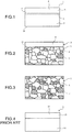
- Fig. 2 is an enlarged view illustrating a structure of the high ferrite phase portion 5 near the bonding surface 21 of the back-metal layer 2.
- Fig. 3 is an enlarged view illustrating a structure of a center portion in a thickness direction of the back-metal layer 2 (hereinafter simply referred to as "center portion of the back-metal layer 2").
- center portion of the back-metal layer 2 For easier understanding, a ferrite phase 6 and pearlite 7 in the structure are exaggerated in Figs. 2 and 3 .
- the back-metal layer 2 includes a hypoeutectoid steel including 0.07 to 0.35 mass% of carbon.
- the back-metal layer 2 has a structure including the ferrite phase 6 and the pearlite 7 as illustrated in Fig. 3 . If the carbon content in the hypoeutectoid steel is less than 0.07 mass%, the back-metal layer 2 has low strength, and it causes insufficient strength of the sliding member 1. On the other hand, if the carbon content in the hypoeutectoid steel is more than 0.35 mass%, a ratio of the pearlite 7 in the high ferrite phase portion 5 of the back-metal layer 2 becomes low.
- the back-metal layer 2 may include: 0.07 to 0.35 mass% of carbon; one or more elements selected from 0.4 mass% or less of Si, 1 mass% or less of Mn, 0.04 mass% or less of P, and 0.05 mass% or less of S; and the balance of Fe and inevitable impurities.
- the back-metal layer 2 has a structure including the ferrite phase 6 and the pearlite 7. This does not exclude that a structure of the back-metal layer 2 includes a fine precipitations, for example the fine precipitations undetectable when the structure is observed at a magnification of 1000 times with use of a scanning electron microscope.
- some elements of the copper alloy 4 may be diffused and solid-solved in the ferrite phase 6 near the bonding surface 21 (i.e. near a surface of the high ferrite phase portion 5) during second sintering (described later) which is an interface between the back-metal layer 2 and the sliding layer 3.
- second sintering described later
- a volume ratio Ps of the pearlite 7 in the structure of the high ferrite phase portion 5 is lower by not less than 60% than a volume ratio Pc of the pearlite 7 in the structure at the center portion of the back-metal layer 2. That is, a volume ratio Pc and a volume ratio Ps satisfy a relationship: Ps/Pc ⁇ 0.4.
- the ferrite phase 6 includes a small amount of carbon, which is 0.02 mass% at a maximum.
- the ferrite phase 6 has a composition similar to that of pure iron.
- the pearlite 7 has a lamellar structure in which a ferrite phase and a cementite (iron carbide Fe 3 C) phase are alternately arranged to form a thin plate.
- the pearlite 7 has higher strength than the ferrite phase 6.
- the back-metal layer 2 has higher deformation resistance, as a ratio of the pearlite 7 in the structure is higher.
- the high ferrite phase portion 5 Since the volume ratio of the pearlite 7 in the structure of the high ferrite phase portion 5 is lower by not less than 60% than the volume ratio of the pearlite 7 in the structure at the center portion of the back-metal layer 2, the high ferrite phase portion 5 has lower deformation resistance than the center portion of the back-metal layer 2.
- An area ratio of the pearlite 7 in the structure is measured by taking electronic images of the center portion of the back-metal layer 2 and a portion near the bonding surface 21 of the back-metal layer 2 in a plurality of cross-sectional portions (e.g., 5 portions) cut in a direction parallel to a thickness direction of the sliding member 1 (a direction perpendicular to a sliding surface of the sliding layer 3).
- the images are taken at a magnification of 500 times with use of an electron microscope, and measuring the area ratio of the pearlite 7 in the images with a general image analysis method (analysis software: Image-Pro Plus (Version 4.5) manufactured by Planetron, Inc.).
- the area ratio of the pearlite 7 at the portion near the bonding surface of the back-metal layer 2 is lower by not less than 60% than the area ratio of the pearlite 7 in the structure at the center portion of the back-metal layer 2, it can be confirmed that the high ferrite phase portion 5 is located at the bonding surface 21 of the back-metal layer 2.
- the center portion of the back-metal layer 2 does not need to be strictly a center position in the thickness direction of the back-metal layer 2. This is because a structure between the back surface 22 of the back-metal layer 2 and the high ferrite phase portion 5 is substantially uniform (with almost the same area ratio of the ferrite phase 6 / the pearlite 7).
- the "center portion (in the thickness direction) of the back-metal layer 2" described herein includes the center position in the thickness direction of the back-metal layer 2 and a portion near the center position.
- the volume ratio of the pearlite 7 in the structure is measured as the area ratio in cross-sectional view. A value of the area ratio corresponds to a value of the volume ratio of the pearlite 7 in the structure.
- the area ratio of the pearlite 7 at the surface (bonding surface 21) of the high ferrite phase portion 5 is preferably 0 to 2% in order to increase bonding strength between the sliding layer 3 and the high ferrite phase portion 5.
- the area ratio of the pearlite 7 at the surface of the high ferrite phase portion 5 can not be directly measured, but can be obtained by taking images of a plurality of portions of the cross-sectional structure by the same method described above and measuring a ratio of a length of a line included within the pearlite 7 in relation to an entire length of a line indicating the bonding surface 21 of the high ferrite phase portion 5 which is an interface between the high ferrite phase portion 5 and the sliding layer 3 in the images, with use of a general image analysis method (analysis software: Image-Pro Plus (Version 4.5) manufactured by Planetron, Inc.). This ratio corresponds to the area rate of the pearlite 7 at the surface of the high ferrite phase portion 5.
- the copper alloy 4 of the sliding layer 3 may be a general copper alloy for a sliding member, and a composition thereof is not limited.
- the copper alloy 4 includes 0.5 to 12 mass% of Sn, 0.01 to 0.2 mass% of P, and the balance of Cu and inevitable impurities.
- Sn and P have an effect of increasing strength of the copper alloy. If the Sn or P content is less than its lower limit, the effect is insufficient. If the Sn or P content is more than its upper limit, the copper alloy becomes brittle.
- the copper alloy 4 may include: 0.5 to 12 mass% of Sn; 0.01 to 0.2 mass% of P; and one or more elements selected from 0.1 to 15 mass% of Ni, 0.5 to 10 mass% of Fe, 0.01 to 5 mass% of Al, 0.01 to 5 mass% of Si, 0.1 to 5 mass% of Mn, 0.1 to 30 mass% of Zn, 0.1 to 5 mass% of Sb, 0.1 to 5 mass% of In, 0.1 to 5 mass% of Ag, 0.5 to 25 mass% of Pb, and 0.5 to 20 mass% of Bi.
- Ni, Fe, Al, Si, Mn, Zn, Sb, In and Ag have an effect of increasing strength of the copper alloy 4.
- the copper alloy 4 becomes brittle.
- Pb and Bi have an effect of increasing a lubricating property of the copper alloy 4. If the Pb or Bi content is less than its lower limit, the effect is insufficient. If the Pb or Bi content is more than its upper limit, the copper alloy 4 becomes brittle.
- a total amount of the elements is preferably not more than 40 mass%.
- the sliding layer 3 may further include 0.1 to 10 volume % of hard particles composed of one or more selected from Al 2 O 3 , SiO 2 , AlN, Mo 2 C, WC, Fe 2 P, and Fe 3 P.
- the hard particles are dispersed in a matrix of the copper alloy 4 of the sliding layer 3 and have an effect of improving wear resistance of the sliding layer 3. If an amount of the hard particles is less than the lower limit, the effect is insufficient. If the amount of the hard particles is more than the upper limit, the sliding layer 3 becomes brittle.
- the sliding layer 3 may further include 0.1 to 10 volume % of a solid lubricant composed of one or more selected from MoS 2 , WS 2 , graphite, and h-BN.
- the solid lubricant particles are dispersed in the matrix of the copper alloy 4 of the sliding layer 3 and have an effect of improving a lubricating property of the sliding layer 3. If an amount of the solid lubricant is less than the lower limit, the effect is insufficient. If the amount of the solid lubricant content is more than the upper limit, the sliding layer 3 becomes brittle.
- the back-metal layer 2 includes a hypoeutectoid steel including 0.07 to 0.35 mass% of carbon.
- the hypoeutectoid steel has a structure including a ferrite phase 6 and pearlite 7.
- a ratio of the pearlite 7 is determined according to the carbon content and is normally not more than 30 volume %.
- the center portion of the back-metal layer 2 has such a normal structure of the hypoeutectoid steel.
- the high ferrite phase portion 5 is formed in which a volume ratio of the pearlite 7 is lower by not less than 60% than a volume ratio of the pearlite 7 in the structure at the center portion of the back-metal layer.
- the high ferrite phase portion 5 has lower deformation resistance than other regions (especially, near the center portion) of the back-metal layer 2.
- a copper alloy powder having the composition described above for a sliding layer is prepared.
- a sliding layer includes the hard particles and/or the solid lubricant, a mixed powder of the copper alloy powder and the hard particles and/or the solid lubricant particles is produced.
- the prepared copper alloy powder or mixed powder is scattered on a steel (hypoeutectoid steel) plate having the composition described above. Then, it is first-sintered in a sintering furnace in a reducing atmosphere at a temperature of 800°C to 950°C without applying pressure to the scattered powder, to form a porous copper alloy layer on the steel plate. Then, the copper alloy layer is cooled to a room temperature.
- the porous copper alloy layer on the steel plate is subjected to first-rolling in order to make the porous layer dense and activate a region near a surface of the steel plate in contact with the copper alloy layer.
- first rolling has been performed in order to reduce pores and dense a porous copper alloy layer, buts a steel plate has been hardly rolled.
- a reduction in the first rolling is increased as compared with the conventional one, and the rolling is further proceeded after the porous copper alloy layer is densified.
- the porous copper alloy layer before the first-rolling has lower hardness than the steel plate.
- the porous copper alloy layer Until the porous copper alloy layer has been densified in the first rolling, only the porous copper alloy layer is plastically deformed and thus can be sufficiently work hardened.
- the densified and work-hardened copper alloy layer is further rolled, the hardness of the copper alloy layer and that of the steel plate are reversed, so that the copper alloy layer has higher hardness than the steel plate (e.g., a surface of the densified copper alloy layer subjected to the first rolling has a Vickers hardness (Hv) higher by approximately 20 HV than a Vickers hardness of a back surface of the steel plate).
- Hv Vickers hardness
- the steel plate is also rolled in the rolling. Accordingly, in the first rolling, more strain is introduced in the region near the surface of the steel plate in contact with the hardened copper alloy layer than an inner portion of the steel plate, thereby the region becomes in an active state.
- the rolled member is subjected to second sintering in the sintering furnace in a reducing atmosphere at a temperature of 800°C to 950°C to sinter the copper alloy layer, and is then cooled to a room temperature.
- a high ferrite phase portion is formed at a surface of the back-metal layer, which surface is an interface between the back-metal layer and the copper alloy layer.
- the back-metal layer (the steel plate) of the rolled member reaches an A1 transformation point (727°C) during heating in the second sintering step, a recrystallization occurs earlier at a region near a bonding surface of the back-metal layer which is the interface between the back-metal layer and the copper alloy layer, since the region is in a more active state than the inner portion of the back-metal layer. Accordingly, immediately before the temperature reaches the A1 transformation point, a ratio of a ferrite phase and pearlite is not different between the structure of the portion near the bonding surface and that of the inner portion of the back-metal layer. However, a size of grains of the ferrite phase is larger at the region near the surface of the back-metal layer than those at the inner portion.
- the pearlite transforms into an austenitic phase, so that the back-metal layer has a structure including the ferrite phase and the austenitic phase (immediately after the temperature reaches the A1 transformation point, there is no difference in a ratio of the austenitic phase in the structure and concentration of carbon atoms solid-solved in the austenitic phase between the region near the bonding surface and the inner portion).
- the ferrite phase gradually transforms into an austenitic phase, so that the ratio of the ferrite phase in the structure is reducing.
- the ferrite phase at the region near the bonding surface of the back-metal layer has a larger grain size and is more stable than that at the inner portion of the back-metal layer, and is thus less likely to be transformed into an austenitic phase.
- the ratio of the austenitic phase in the structure at the region near the surface is always lower than the ratio at the inner portion.
- carbon atoms included in the pearlite are solid-solved in the austenitic phase that present by a smaller amount (volume) at the region near the surface than at the inner portion of the back-metal layer.
- This causes a difference in concentration of carbon atoms in the austenitic phase between at the region near the surface and at the inner portion of the back-metal layer.
- carbon atoms in the austenitic phase at the region near the surface diffuse into the austenitic phase of the inner portion of the back-metal layer.
- the amount of carbon at the region near the surface becomes smaller than that at the inner portion of the back-metal layer.
- the back-metal layer reaches the A1 transformation point during cooling, its structure transforms into a ferrite phase and pearlite.
- the volume ratio of the pearlite in the structure at the region near the surface becomes lower than that at the inner portion of the back-metal layer for the following reasons. That is, as described above, during the temperature rise,
- the first rolling is performed only to such an extent that the porous copper alloy layer is densified and the back-metal layer is not rolled.
- more strain is not introduced into the region near the interface of the back-metal layer (the steel plate) with the densified copper alloy layer than in the inner portion of the back-metal layer, and the region near the interface is not in an active state.
- the subsequent second sintering step there is no difference in the volume ratio of the pearlite between the region near the surface and the inner portion of the back-metal layer.
- the sliding member of the present invention is not limited to a bearing for an internal combustion engine and an automatic transmission, but can be applied to a bearing for various machines.
- a shape of the bearing is not limited to a cylindrical shape or a semi-cylindrical shape.
- the sliding member of the present invention can also be applied to an annular shaped or semi-annular shaped thrust bearing for bearing an axial load of a shaft member or an annular shaped end plate having a substantially U-shaped cross section for a clutch (one-way clutch) of an automatic transmission.
- the sliding member of the present invention may have a coating layer on the surface of the sliding layer and/or the back-metal layer.
- the coating layer may include Sn, Bi, or Pb or an alloy based on these metals, or include synthetic resin, or the coating layer may be based on synthetic resin.
- a surface of the sliding layer is referred to as a "sliding surface” in this description, even when the coating layer is applied to the surface of the sliding layer.
Landscapes
- Engineering & Computer Science (AREA)
- Chemical & Material Sciences (AREA)
- Mechanical Engineering (AREA)
- General Engineering & Computer Science (AREA)
- Materials Engineering (AREA)
- Metallurgy (AREA)
- Organic Chemistry (AREA)
- Ceramic Engineering (AREA)
- Sliding-Contact Bearings (AREA)
Description
- The present invention relates to a sliding member, for example used for a bearing of an internal combustion engine or an automatic transmission or for bearings of various machines. The present invention specifically relates to a sliding member including a sliding layer on a back-metal layer.
- For a bearing device of an internal combustion engine, an automatic transmission and the like, a cylindrical or semi-cylindrical sliding bearing formed from a sliding member including a sliding layer including a copper alloy and a steel back-metal layer has been used. For example,
JP 06-322462A JP 2002-220631 A - During operation of the internal combustion engine or the automatic transmission, a sliding member bears a dynamic load from a counter shaft member on a sliding surface of a sliding layer. For example, for holding a sliding bearing, the bearing is fitted into a cylindrical hole of the internal combustion engine, the automatic transmission or the like, and bears a dynamic load from a rotating counter shaft member. In recent years, in order to reduce fuel consumption, weight reduction has been achieved in the internal combustion engine and the automatic transmission, and this has caused the bearing housing to have lower rigidity than before. Accordingly, during operation of the internal combustion engine, in the bearing device of the internal combustion engine and the automatic transmission connected to the internal combustion engine, the bearing housing is more likely to be elastically deformed by a dynamic load from a counter shaft member. Due to the deformation of the bearing housing, the sliding member (sliding bearing) fitted into the bearing holding hole of the bearing housing is elastically deformed in a circumferential direction. Thus, when a varying circumferential force is applied to the sliding bearing of the conventional sliding member, since there is a difference in amount of elastic deformation between the sliding layer including the copper alloy and the steel back-metal layer, shear occurs in some cases at an interface between the sliding layer and the steel back-metal layer. This may cause breakage of the sliding member.
-
JP 2006-22869A JP 2006-22869A -
US 2015 2 67 747 A1 discloses a sliding member comprising all the features ofclaim 1 except the sliding layer comprising a copper alloy. Here, a sliding layer comprising a nickel alloy is mentioned. - The technique of
JP 2006-22869A - According to an aspect of the present invention, provided is a sliding member including: a back-metal layer having a back surface and a bonding surface; and a sliding layer including a copper alloy on the bonding surface of the back-metal layer. The back-metal layer includes a hypoeutectoid steel including 0.07 to 0.35 mass% of carbon and has a structure including a ferrite phase and pearlite. According to the present invention, the back-metal layer includes a high ferrite phase portion at the bonding surface. A volume ratio Pc and a volume ratio Ps satisfy Ps/Pc ≤ 0.4, where the volume ratio Pc is a volume ratio of pearlite in the structure at a center portion in a thickness direction of the back-metal layer, and the volume ratio Ps is a volume ratio of pearlite in the high ferrite phase portion.
- According to an embodiment, the high ferrite phase portion preferably has a thickness T1 of 1 to 50 µm.
- According to an embodiment, a ratio X1 (= T1/T) of the thickness T1 of the high ferrite phase portion in relation to a thickness T of the back-metal layer is preferably not more than 0.07.
- According to an embodiment, the back-metal layer preferably includes 0.07 to 0.35 mass% of C, 0.4 mass% or less of Si, 1 mass% or less of Mn, 0.04 mass% or less of P, 0.05 mass% or less of S, and the balance of Fe and inevitable impurities. The copper alloy preferably includes 0.5 to 12 mass% of Sn, 0.01 to 0.2 mass% of P, and the balance of Cu and inevitable impurities. The copper alloy may further include one or more elements selected from 0.1 to 15 mass% of Ni, 0.5 to 10 mass% of Fe, 0.01 to 5 mass% of Al, 0.01 to 5 mass% of Si, 0.1 to 5 mass% of Mn, 0.1 to 30 mass% of Zn, 0.1 to 5 mass% of Sb, 0.1 to 5 mass% of In, 0.1 to 5 mass% of Ag, 0.5 to 25 mass% of Pb, and 0.5 to 20 mass% of Bi.
- According to an embodiment, the sliding layer may include 0.1 to 10 volume % of hard particles composed of one or more selected from Al2O3, SiO2, AlN, Mo2C, WC, Fe2P, and Fe3P, which are dispersed in a matrix of the copper alloy. The sliding layer may include 0.1 to 10 volume % of a solid lubricant composed of one or more selected from MoS2, WS2, graphite, and h-BN, which are dispersed in a matrix of the copper alloy. The sliding layer may include both the hard particles and the solid lubricant in the matrix of the copper alloy. Alternatively, the sliding layer may include either the hard particles or the solid lubricant alone.
- According to the sliding member of the present invention, the high ferrite phase portion is positioned at the bonding surface of the back-metal layer, which is an interface between the back-metal layer and the sliding layer. The high ferrite phase portion has a volume ratio of the pearlite lower by not less than 60% than the volume ratio of the pearlite in the structure at the center portion in the thickness direction of the back-metal layer. A difference in elastic deformation between the ferrite phase and the copper alloy is small as compared with a difference in elastic deformation between the pearlite and the copper alloy. Accordingly, when an external force is applied to the sliding member, a difference in amount of elastic deformation is small at an interface between the copper alloy of the sliding layer and the high ferrite phase portion of the back-metal layer. Thus, shear is less likely to occur at the interface, and thus the copper alloy of the sliding layer is strongly bonded to the back-metal layer.
- On the other hand, a portion of the back-metal layer except the high ferrite phase portion can ensure strength necessary for the back-metal layer. Except the high ferrite phase portion, the back-metal layer has a structure of a hypoeutectoid steel including a normal amount of pearlite, and thus has high strength. Accordingly, the sliding member is less likely to be plastically deformed by circumferential stress applied to the sliding member when the sliding member is fitted into a bearing housing or by circumferential force applied to the sliding member during operation of a bearing device.
-
-
Fig. 1 is a schematic diagram of a cross section in a direction perpendicular to a sliding surface of a sliding layer of a sliding member according to the present invention. -
Fig. 2 is a schematic diagram of a cross-sectional structure of a high ferrite phase portion of a back-metal layer illustrated inFig. 1 . -
Fig. 3 is a schematic diagram of a cross-sectional structure at a center portion in a thickness direction of the back-metal layer illustrated inFig. 1 . -
Fig. 4 is a schematic diagram of a cross section in a direction perpendicular to a sliding surface of a sliding layer of a conventional sliding member. -
Fig. 4 is a schematic diagram illustrating a cross section of a conventional slidingmember 11. The slidingmember 11 is configured such that a slidinglayer 13 of acopper alloy 14 is located on a surface of a back-metal layer 12. The back-metal layer 12 of a hypoeutectoid steel includes 0.07 to 0.35 mass% of carbon and has a normal structure of a hypoeutectoid steel (corresponding to a structure illustrated inFig. 3 ). That is, the back-metal layer 12 has a structure including mainly a ferrite phase 6 andgranular pearlite 7 is dispersed in a matrix of the ferrite phase. The back-metal layer 12 has a uniform structure throughout a thickness direction of the back-metal layer 12. Accordingly, the back-metal layer 12 has substantially uniform deformation resistance to an external force in the thickness direction of the back-metal layer 12. - As described above, during operation of a bearing device, a bearing housing is more likely to be elastically deformed by a dynamic load from a counter shaft member. In the conventional sliding
member 11, therefore, a circumferential force which varies according to deformation of a bearing housing is applied to the sliding member (sliding bearing) fitted into a bearing holding hole of the bearing housing, and the force causes elastic deformation to the sliding member. In the conventional slidingmember 11, the back-metal layer 12 has a normal structure of a hypoeutectoid steel. Thus, the back-metal layer 12 has higher strength and resultant higher deformation resistance than thecopper alloy 14 of the slidinglayer 13. Accordingly, a difference in amount of elastic deformation between the back-metal layer 12 and thecopper alloy 14 of the slidinglayer 13 is large at an interface between the back-metal layer 12 and the slidinglayer 13. Thus, shear is more likely to occur between the back-metal layer 12 and thesliding layer 13. - An embodiment of a sliding
member 1 according to the present invention will be described below with reference toFigs. 1 to 3. Fig. 1 is a schematic diagram illustrating a cross section of the slidingmember 1 including a slidinglayer 3 including acopper alloy 4 located on a back-metal layer 2. The back-metal layer 2 has a surface (bonding surface 21) on which the slidinglayer 3 is located and aback surface 22 opposite to thebonding surface 21. A high ferrite phase portion 5 (described below) is formed at thebonding surface 21 of the back-metal layer 2. Thebonding surface 21 is an interface between the back-metal layer 2 and thecopper alloy 4. -
Fig. 2 is an enlarged view illustrating a structure of the highferrite phase portion 5 near thebonding surface 21 of the back-metal layer 2.Fig. 3 is an enlarged view illustrating a structure of a center portion in a thickness direction of the back-metal layer 2 (hereinafter simply referred to as "center portion of the back-metal layer 2"). For easier understanding, a ferrite phase 6 andpearlite 7 in the structure are exaggerated inFigs. 2 and 3 . - The back-
metal layer 2 includes a hypoeutectoid steel including 0.07 to 0.35 mass% of carbon. The back-metal layer 2 has a structure including the ferrite phase 6 and thepearlite 7 as illustrated inFig. 3 . If the carbon content in the hypoeutectoid steel is less than 0.07 mass%, the back-metal layer 2 has low strength, and it causes insufficient strength of the slidingmember 1. On the other hand, if the carbon content in the hypoeutectoid steel is more than 0.35 mass%, a ratio of thepearlite 7 in the highferrite phase portion 5 of the back-metal layer 2 becomes low. - The back-
metal layer 2 may include: 0.07 to 0.35 mass% of carbon; one or more elements selected from 0.4 mass% or less of Si, 1 mass% or less of Mn, 0.04 mass% or less of P, and 0.05 mass% or less of S; and the balance of Fe and inevitable impurities. The back-metal layer 2 has a structure including the ferrite phase 6 and thepearlite 7. This does not exclude that a structure of the back-metal layer 2 includes a fine precipitations, for example the fine precipitations undetectable when the structure is observed at a magnification of 1000 times with use of a scanning electron microscope. - Furthermore, in some cases, some elements of the copper alloy 4 (described later) may be diffused and solid-solved in the ferrite phase 6 near the bonding surface 21 (i.e. near a surface of the high ferrite phase portion 5) during second sintering (described later) which is an interface between the back-
metal layer 2 and the slidinglayer 3. Such cases are also included in the scope of the present invention. - A volume ratio Ps of the
pearlite 7 in the structure of the highferrite phase portion 5 is lower by not less than 60% than a volume ratio Pc of thepearlite 7 in the structure at the center portion of the back-metal layer 2. That is, a volume ratio Pc and a volume ratio Ps satisfy a relationship: Ps/Pc ≤ 0.4. - The ferrite phase 6 includes a small amount of carbon, which is 0.02 mass% at a maximum. The ferrite phase 6 has a composition similar to that of pure iron. On the other hand, the
pearlite 7 has a lamellar structure in which a ferrite phase and a cementite (iron carbide Fe3C) phase are alternately arranged to form a thin plate. Thepearlite 7 has higher strength than the ferrite phase 6. Thus, the back-metal layer 2 has higher deformation resistance, as a ratio of thepearlite 7 in the structure is higher. Since the volume ratio of thepearlite 7 in the structure of the highferrite phase portion 5 is lower by not less than 60% than the volume ratio of thepearlite 7 in the structure at the center portion of the back-metal layer 2, the highferrite phase portion 5 has lower deformation resistance than the center portion of the back-metal layer 2. - An area ratio of the
pearlite 7 in the structure is measured by taking electronic images of the center portion of the back-metal layer 2 and a portion near thebonding surface 21 of the back-metal layer 2 in a plurality of cross-sectional portions (e.g., 5 portions) cut in a direction parallel to a thickness direction of the sliding member 1 (a direction perpendicular to a sliding surface of the sliding layer 3). The images are taken at a magnification of 500 times with use of an electron microscope, and measuring the area ratio of thepearlite 7 in the images with a general image analysis method (analysis software: Image-Pro Plus (Version 4.5) manufactured by Planetron, Inc.). When the area ratio of thepearlite 7 at the portion near the bonding surface of the back-metal layer 2 is lower by not less than 60% than the area ratio of thepearlite 7 in the structure at the center portion of the back-metal layer 2, it can be confirmed that the highferrite phase portion 5 is located at thebonding surface 21 of the back-metal layer 2. - The center portion of the back-
metal layer 2 does not need to be strictly a center position in the thickness direction of the back-metal layer 2. This is because a structure between theback surface 22 of the back-metal layer 2 and the highferrite phase portion 5 is substantially uniform (with almost the same area ratio of the ferrite phase 6 / the pearlite 7). Thus, the "center portion (in the thickness direction) of the back-metal layer 2" described herein includes the center position in the thickness direction of the back-metal layer 2 and a portion near the center position. In the above observation, the volume ratio of thepearlite 7 in the structure is measured as the area ratio in cross-sectional view. A value of the area ratio corresponds to a value of the volume ratio of thepearlite 7 in the structure. - The area ratio of the
pearlite 7 at the surface (bonding surface 21) of the highferrite phase portion 5 is preferably 0 to 2% in order to increase bonding strength between the slidinglayer 3 and the highferrite phase portion 5. The area ratio of thepearlite 7 at the surface of the highferrite phase portion 5 can not be directly measured, but can be obtained by taking images of a plurality of portions of the cross-sectional structure by the same method described above and measuring a ratio of a length of a line included within thepearlite 7 in relation to an entire length of a line indicating thebonding surface 21 of the highferrite phase portion 5 which is an interface between the highferrite phase portion 5 and the slidinglayer 3 in the images, with use of a general image analysis method (analysis software: Image-Pro Plus (Version 4.5) manufactured by Planetron, Inc.). This ratio corresponds to the area rate of thepearlite 7 at the surface of the highferrite phase portion 5. - The high
ferrite phase portion 5 preferably has a thickness T1 of 1 to 50 µm from thebonding surface 21. More preferably, the highferrite phase portion 5 has a thickness T1 of 1 to 20 µm.If the highferrite phase portion 5 has a thickness of less than 1 µm, the highferrite phase portion 5 is not formed partially on thebonding surface 21 of the back-metal layer 2, in some cases. In a general sliding member, the back-metal layer 2 has a thickness of 0.7 mm at a minimum. Thus, when the highferrite phase portion 5 has a thickness T1 of not more than 50 µm, strength of the back-metal layer 2 is little influenced by the thickness T1. Furthermore, a ratio X1 (X1 = T1/T) of the thickness T1 of the highferrite phase portion 5 in relation to a thickness T of the back-metal layer 2 is preferably not more than 0.07. - The
copper alloy 4 of the slidinglayer 3 may be a general copper alloy for a sliding member, and a composition thereof is not limited. For example, thecopper alloy 4 includes 0.5 to 12 mass% of Sn, 0.01 to 0.2 mass% of P, and the balance of Cu and inevitable impurities. Sn and P have an effect of increasing strength of the copper alloy. If the Sn or P content is less than its lower limit, the effect is insufficient. If the Sn or P content is more than its upper limit, the copper alloy becomes brittle. - Alternatively, the
copper alloy 4 may include: 0.5 to 12 mass% of Sn; 0.01 to 0.2 mass% of P; and one or more elements selected from 0.1 to 15 mass% of Ni, 0.5 to 10 mass% of Fe, 0.01 to 5 mass% of Al, 0.01 to 5 mass% of Si, 0.1 to 5 mass% of Mn, 0.1 to 30 mass% of Zn, 0.1 to 5 mass% of Sb, 0.1 to 5 mass% of In, 0.1 to 5 mass% of Ag, 0.5 to 25 mass% of Pb, and 0.5 to 20 mass% of Bi. Ni, Fe, Al, Si, Mn, Zn, Sb, In and Ag have an effect of increasing strength of thecopper alloy 4. If the content of any of these elements is less than its lower limit, the effect is insufficient. If the content of any of these elements is more than its upper limit, thecopper alloy 4 becomes brittle. Pb and Bi have an effect of increasing a lubricating property of thecopper alloy 4. If the Pb or Bi content is less than its lower limit, the effect is insufficient. If the Pb or Bi content is more than its upper limit, thecopper alloy 4 becomes brittle. When thecopper alloy 4 includes two or more of these selected elements, a total amount of the elements is preferably not more than 40 mass%. - The sliding
layer 3 may further include 0.1 to 10 volume % of hard particles composed of one or more selected from Al2O3, SiO2, AlN, Mo2C, WC, Fe2P, and Fe3P. The hard particles are dispersed in a matrix of thecopper alloy 4 of the slidinglayer 3 and have an effect of improving wear resistance of the slidinglayer 3. If an amount of the hard particles is less than the lower limit, the effect is insufficient. If the amount of the hard particles is more than the upper limit, the slidinglayer 3 becomes brittle. - The sliding
layer 3 may further include 0.1 to 10 volume % of a solid lubricant composed of one or more selected from MoS2, WS2, graphite, and h-BN. The solid lubricant particles are dispersed in the matrix of thecopper alloy 4 of the slidinglayer 3 and have an effect of improving a lubricating property of the slidinglayer 3. If an amount of the solid lubricant is less than the lower limit, the effect is insufficient. If the amount of the solid lubricant content is more than the upper limit, the slidinglayer 3 becomes brittle. - The back-
metal layer 2 includes a hypoeutectoid steel including 0.07 to 0.35 mass% of carbon. The hypoeutectoid steel has a structure including a ferrite phase 6 andpearlite 7. A ratio of thepearlite 7 is determined according to the carbon content and is normally not more than 30 volume %. The center portion of the back-metal layer 2 has such a normal structure of the hypoeutectoid steel. However, at thebonding surface 21 of the back-metal layer 2, which is an interface between the back-metal layer 2 and the slidinglayer 3, the highferrite phase portion 5 is formed in which a volume ratio of thepearlite 7 is lower by not less than 60% than a volume ratio of thepearlite 7 in the structure at the center portion of the back-metal layer. The highferrite phase portion 5 has lower deformation resistance than other regions (especially, near the center portion) of the back-metal layer 2. Thus, even when a circumferential force due to elastic deformation of a bearing housing is applied to the slidingmember 1 used in a bearing device to cause elastically deformation in the slidingmember 1, a difference in deformation resistance between thecopper alloy 4 of the slidinglayer 3 and the highferrite phase portion 5 of the back-metal layer 2 is small at the interface, thereby a difference in amount of elastic deformation therebetween is small. Accordingly, shear is less likely to occur at the interface between the back-metal layer 2 and the slidinglayer 3. - A method of producing the sliding member according to the present embodiment will be described below.
- First, a copper alloy powder having the composition described above for a sliding layer is prepared. When a sliding layer includes the hard particles and/or the solid lubricant, a mixed powder of the copper alloy powder and the hard particles and/or the solid lubricant particles is produced.
- The prepared copper alloy powder or mixed powder is scattered on a steel (hypoeutectoid steel) plate having the composition described above. Then, it is first-sintered in a sintering furnace in a reducing atmosphere at a temperature of 800°C to 950°C without applying pressure to the scattered powder, to form a porous copper alloy layer on the steel plate. Then, the copper alloy layer is cooled to a room temperature.
- Next, the porous copper alloy layer on the steel plate is subjected to first-rolling in order to make the porous layer dense and activate a region near a surface of the steel plate in contact with the copper alloy layer. In a conventional process of production of a sliding member, first rolling has been performed in order to reduce pores and dense a porous copper alloy layer, buts a steel plate has been hardly rolled. In the production of the sliding member according to the present invention, however, a reduction in the first rolling is increased as compared with the conventional one, and the rolling is further proceeded after the porous copper alloy layer is densified. The porous copper alloy layer before the first-rolling has lower hardness than the steel plate. Until the porous copper alloy layer has been densified in the first rolling, only the porous copper alloy layer is plastically deformed and thus can be sufficiently work hardened. When the densified and work-hardened copper alloy layer is further rolled, the hardness of the copper alloy layer and that of the steel plate are reversed, so that the copper alloy layer has higher hardness than the steel plate (e.g., a surface of the densified copper alloy layer subjected to the first rolling has a Vickers hardness (Hv) higher by approximately 20 HV than a Vickers hardness of a back surface of the steel plate). Thus, the steel plate is also rolled in the rolling. Accordingly, in the first rolling, more strain is introduced in the region near the surface of the steel plate in contact with the hardened copper alloy layer than an inner portion of the steel plate, thereby the region becomes in an active state.
- Next, the rolled member is subjected to second sintering in the sintering furnace in a reducing atmosphere at a temperature of 800°C to 950°C to sinter the copper alloy layer, and is then cooled to a room temperature. At this point, a high ferrite phase portion is formed at a surface of the back-metal layer, which surface is an interface between the back-metal layer and the copper alloy layer.
- It is presumed that the high ferrite phase portion is formed by a mechanism below.
- Before the back-metal layer (the steel plate) of the rolled member reaches an A1 transformation point (727°C) during heating in the second sintering step, a recrystallization occurs earlier at a region near a bonding surface of the back-metal layer which is the interface between the back-metal layer and the copper alloy layer, since the region is in a more active state than the inner portion of the back-metal layer. Accordingly, immediately before the temperature reaches the A1 transformation point, a ratio of a ferrite phase and pearlite is not different between the structure of the portion near the bonding surface and that of the inner portion of the back-metal layer. However, a size of grains of the ferrite phase is larger at the region near the surface of the back-metal layer than those at the inner portion.
- When the back-metal layer reaches the A1 transformation point, the pearlite transforms into an austenitic phase, so that the back-metal layer has a structure including the ferrite phase and the austenitic phase (immediately after the temperature reaches the A1 transformation point, there is no difference in a ratio of the austenitic phase in the structure and concentration of carbon atoms solid-solved in the austenitic phase between the region near the bonding surface and the inner portion). Then, as the temperature rises beyond the A1 transformation point to a A3 transformation point (at which the structure becomes a single austenitic phase), the ferrite phase gradually transforms into an austenitic phase, so that the ratio of the ferrite phase in the structure is reducing.
- The ferrite phase at the region near the bonding surface of the back-metal layer has a larger grain size and is more stable than that at the inner portion of the back-metal layer, and is thus less likely to be transformed into an austenitic phase. During the heating, the ratio of the austenitic phase in the structure at the region near the surface is always lower than the ratio at the inner portion.
- Carbon atoms hardly solid-solute in the ferrite phase (approximately 0.02 mass% C solid-solve a maximum). Thus, carbon atoms included in the pearlite are solid-solved in the austenitic phase that present by a smaller amount (volume) at the region near the surface than at the inner portion of the back-metal layer. This causes a difference in concentration of carbon atoms in the austenitic phase between at the region near the surface and at the inner portion of the back-metal layer. In order to reduce the difference, carbon atoms in the austenitic phase at the region near the surface diffuse into the austenitic phase of the inner portion of the back-metal layer. Thus, the amount of carbon at the region near the surface becomes smaller than that at the inner portion of the back-metal layer.
- Then, when the back-metal layer reaches the A1 transformation point during cooling, its structure transforms into a ferrite phase and pearlite. After the cooling, the volume ratio of the pearlite in the structure at the region near the surface becomes lower than that at the inner portion of the back-metal layer for the following reasons. That is, as described above, during the temperature rise,
- (i) the amount of carbon included at the region near the bonding surface is smaller than the amount of carbon at the inner portion, and
- (ii) during the temperature rise, the volume ratio of the ferrite phase remaining in the structure is different between the region near the surface and the inner portion.
- In the conventional production, the first rolling is performed only to such an extent that the porous copper alloy layer is densified and the back-metal layer is not rolled. Thus, more strain is not introduced into the region near the interface of the back-metal layer (the steel plate) with the densified copper alloy layer than in the inner portion of the back-metal layer, and the region near the interface is not in an active state. Thus, after the subsequent second sintering step, there is no difference in the volume ratio of the pearlite between the region near the surface and the inner portion of the back-metal layer.
- Furthermore, (as disclosed in
JP 2006-22869A - The sliding member of the present invention is not limited to a bearing for an internal combustion engine and an automatic transmission, but can be applied to a bearing for various machines. Furthermore, a shape of the bearing is not limited to a cylindrical shape or a semi-cylindrical shape. For example, the sliding member of the present invention can also be applied to an annular shaped or semi-annular shaped thrust bearing for bearing an axial load of a shaft member or an annular shaped end plate having a substantially U-shaped cross section for a clutch (one-way clutch) of an automatic transmission.
- Furthermore, the sliding member of the present invention may have a coating layer on the surface of the sliding layer and/or the back-metal layer. The coating layer may include Sn, Bi, or Pb or an alloy based on these metals, or include synthetic resin, or the coating layer may be based on synthetic resin. (Please note that a surface of the sliding layer is referred to as a "sliding surface" in this description, even when the coating layer is applied to the surface of the sliding layer.)
Claims (5)
- A sliding member (1) comprising:a back-metal layer (2) having a back surface (22) and a bonding surface (21); anda sliding layer (3) comprising:a copper alloy (4) on the bonding surface (21) of the back-metal layer (2);optionally, 0.1 to 10 volume % of hard particles composed of one or more selected from Al2O3, SiO2, AIN, Mo2C, WC, Fe2P, and Fe3P, the hard particles being dispersed in a matrix of the copper alloy (4); andoptionally, 0.1 to 10 volume % of a solid lubricant composed of one or more selected from MoS2, WS2, graphite, and h-BN, the lubricant being dispersed in a matrix of the copper alloy (4),wherein the back-metal layer (2) comprises a hypoeutectoid steel including 0.07 to 0.35 mass% of carbon and has a structure comprising a ferrite phase (6) and pearlite (7),wherein the back-metal layer (2) comprises a high ferrite phase portion (5) at the bonding surface (21), andwherein a volume ratio Pc and a volume ratio Ps satisfy

- The sliding member according to claim 1, wherein the high ferrite phase portion (5) has a thickness T1 of 1 to 50 µm.
- The sliding member according to claim 1 or 2, wherein a ratio X1 of the thickness T1 of the high ferrite phase portion (5) in relation to a thickness T of the back-metal layer (2) is not more than 0.07.
- The sliding member according to any one of the preceding claims, wherein the back-metal layer (2) comprises 0.07 to 0.35 mass% of C, not more than 0.4 mass% of Si, not more than 1 mass% of Mn, not more than 0.04 mass% of P, not more than 0.05 mass% of S, and the balance of Fe and inevitable impurities.
- The sliding member according to any one of the preceding claims, wherein the copper alloy (4) comprises;0.5 to 12 mass% of Sn,0.01 to 0.2 mass% of Poptionally, one or more elements selected from 0.1 to 15 mass% of Ni, 0.5 to 10 mass% of Fe, 0.01 to 5 mass% of A1, 0.01 to 5 mass% of Si, 0.1 to 5 mass% of Mn, 0.1 to 30 mass% of Zn, 0.1 to 5 mass% of Sb, 0.1 to 5 mass% of In, 0.1 to 5 mass% of Ag, 0.5 to 25 mass% of Pb, and 0.5 to 20 mass% of Bi;, andthe balance of Cu and inevitable impurities.
Applications Claiming Priority (1)
| Application Number | Priority Date | Filing Date | Title |
|---|---|---|---|
| JP2018059981A JP7111484B2 (en) | 2018-03-27 | 2018-03-27 | sliding member |
Publications (2)
| Publication Number | Publication Date |
|---|---|
| EP3550163A1 EP3550163A1 (en) | 2019-10-09 |
| EP3550163B1 true EP3550163B1 (en) | 2021-05-05 |
Family
ID=65801907
Family Applications (1)
| Application Number | Title | Priority Date | Filing Date |
|---|---|---|---|
| EP19162305.7A Revoked EP3550163B1 (en) | 2018-03-27 | 2019-03-12 | Sliding member |
Country Status (5)
| Country | Link |
|---|---|
| US (1) | US10955003B2 (en) |
| EP (1) | EP3550163B1 (en) |
| JP (1) | JP7111484B2 (en) |
| KR (1) | KR102154090B1 (en) |
| CN (1) | CN110307253B (en) |
Cited By (1)
| Publication number | Priority date | Publication date | Assignee | Title |
|---|---|---|---|---|
| DE102024106060A1 (en) * | 2024-03-01 | 2025-09-04 | Ks Gleitlager Gmbh | Plain bearing composite material |
Families Citing this family (7)
| Publication number | Priority date | Publication date | Assignee | Title |
|---|---|---|---|---|
| JP7389600B2 (en) * | 2019-09-26 | 2023-11-30 | 大同メタル工業株式会社 | sliding member |
| JP7389601B2 (en) * | 2019-09-26 | 2023-11-30 | 大同メタル工業株式会社 | sliding member |
| JP7344093B2 (en) * | 2019-11-07 | 2023-09-13 | 大同メタル工業株式会社 | sliding member |
| CN111074090A (en) * | 2019-12-05 | 2020-04-28 | 洛阳轴承研究所有限公司 | Copper alloy material for high-bearing thrust bearing, preparation method of copper alloy material and high-bearing thrust bearing for electric submersible pump |
| CN110983151B (en) * | 2019-12-10 | 2021-09-21 | 华南理工大学 | High-iron copper-based oil-retaining bearing material containing nano WC and preparation method thereof |
| JP7032469B2 (en) * | 2020-03-26 | 2022-03-08 | 大同メタル工業株式会社 | Sliding member |
| CN113005326B (en) * | 2021-02-25 | 2022-03-22 | 宁波金田铜业(集团)股份有限公司 | Copper alloy strip and preparation method thereof |
Citations (3)
| Publication number | Priority date | Publication date | Assignee | Title |
|---|---|---|---|---|
| US5429876A (en) | 1993-05-13 | 1995-07-04 | Daido Metal Company Ltd. | Copper-lead based bearing alloy material excellent in corrosion resistance and a method of producing the same |
| JPH0941033A (en) | 1995-08-02 | 1997-02-10 | Kanai Hiroaki | Nondecarburizing annealing method for steel wire |
| US20150267747A1 (en) | 2014-03-24 | 2015-09-24 | Daido Metal Company Ltd. | Sliding member |
Family Cites Families (16)
| Publication number | Priority date | Publication date | Assignee | Title |
|---|---|---|---|---|
| JPH0726125B2 (en) * | 1990-03-29 | 1995-03-22 | 大同メタル工業株式会社 | Method of manufacturing bimetal for plain bearing |
| JP3357561B2 (en) * | 1997-01-29 | 2002-12-16 | 大同メタル工業株式会社 | Multi-layer resin sliding material |
| JP4301416B2 (en) * | 1997-10-23 | 2009-07-22 | 大豊工業株式会社 | Slide bearing and bearing device for internal combustion engine |
| JP4988093B2 (en) | 2001-01-24 | 2012-08-01 | 大豊工業株式会社 | Phosphor bronze composite sintered material |
| JP2003089831A (en) | 2001-07-12 | 2003-03-28 | Komatsu Ltd | Copper-based sintered sliding material and multi-layer sintered sliding member |
| JP2006022869A (en) | 2004-07-07 | 2006-01-26 | Nsk Ltd | Universal joint |
| KR20110042365A (en) | 2008-09-10 | 2011-04-26 | 다이호 고교 가부시키가이샤 | Sliding parts made of PU-free Cu-based sintered materials |
| EP2431488A4 (en) * | 2009-04-28 | 2013-12-11 | Taiho Kogyo Co Ltd | SINTERED LEAD-FREE COPPER SLIP MATERIAL AND SLIPPER PIECE |
| JP5367502B2 (en) * | 2009-08-19 | 2013-12-11 | オイレス工業株式会社 | Iron-based sintered sliding member and manufacturing method thereof |
| KR101777717B1 (en) | 2010-04-23 | 2017-09-12 | 가부시키가이샤 구리모토 뎃코쇼 | Copper alloy for sliding member |
| JP5377557B2 (en) | 2011-03-30 | 2013-12-25 | 大同メタル工業株式会社 | Copper-based sliding material |
| JP6198652B2 (en) | 2014-03-24 | 2017-09-20 | 大同メタル工業株式会社 | Sliding member |
| JP6198653B2 (en) | 2014-03-24 | 2017-09-20 | 大同メタル工業株式会社 | Sliding member |
| US9677021B2 (en) | 2014-05-14 | 2017-06-13 | Daido Metal Company Ltd. | Sliding member |
| EP3031953B1 (en) | 2014-12-08 | 2018-03-28 | Daido Metal Company Ltd. | Sliding member |
| EP3093136B1 (en) * | 2015-05-14 | 2018-08-01 | Daido Metal Company Ltd. | Sliding member |
-
2018
- 2018-03-27 JP JP2018059981A patent/JP7111484B2/en active Active
-
2019
- 2019-02-15 US US16/276,749 patent/US10955003B2/en active Active
- 2019-02-19 CN CN201910122336.8A patent/CN110307253B/en active Active
- 2019-03-12 EP EP19162305.7A patent/EP3550163B1/en not_active Revoked
- 2019-03-22 KR KR1020190033159A patent/KR102154090B1/en active Active
Patent Citations (3)
| Publication number | Priority date | Publication date | Assignee | Title |
|---|---|---|---|---|
| US5429876A (en) | 1993-05-13 | 1995-07-04 | Daido Metal Company Ltd. | Copper-lead based bearing alloy material excellent in corrosion resistance and a method of producing the same |
| JPH0941033A (en) | 1995-08-02 | 1997-02-10 | Kanai Hiroaki | Nondecarburizing annealing method for steel wire |
| US20150267747A1 (en) | 2014-03-24 | 2015-09-24 | Daido Metal Company Ltd. | Sliding member |
Non-Patent Citations (5)
Cited By (1)
| Publication number | Priority date | Publication date | Assignee | Title |
|---|---|---|---|---|
| DE102024106060A1 (en) * | 2024-03-01 | 2025-09-04 | Ks Gleitlager Gmbh | Plain bearing composite material |
Also Published As
| Publication number | Publication date |
|---|---|
| CN110307253A (en) | 2019-10-08 |
| CN110307253B (en) | 2021-06-01 |
| KR102154090B1 (en) | 2020-09-09 |
| KR20190113608A (en) | 2019-10-08 |
| US20190301529A1 (en) | 2019-10-03 |
| JP7111484B2 (en) | 2022-08-02 |
| US10955003B2 (en) | 2021-03-23 |
| JP2019173060A (en) | 2019-10-10 |
| EP3550163A1 (en) | 2019-10-09 |
Similar Documents
| Publication | Publication Date | Title |
|---|---|---|
| EP3550163B1 (en) | Sliding member | |
| US11098761B2 (en) | Sliding member | |
| JP2003194061A (en) | Copper-based sintered sliding material and its manufacturing method | |
| KR100814656B1 (en) | Free copper alloy sliding material | |
| GB2386610A (en) | A sliding bearing material | |
| US11333198B2 (en) | Sliding member | |
| KR20100049605A (en) | Lead-free, sintered sliding bearing material and sintering powder for producing the latter | |
| JP4122305B2 (en) | Slide bearing for internal combustion engine | |
| EP1273769A2 (en) | Cam lobe piece of built-up type camshaft | |
| EP4431757A1 (en) | Sliding member and bearing | |
| CN117128242B (en) | Copper sliding components | |
| JP7623416B2 (en) | Copper-based sliding materials | |
| KR102890932B1 (en) | Copper-based sliding member | |
| EP2778248B1 (en) | Thrust bearing | |
| CN117128242A (en) | Copper sliding components |
Legal Events
| Date | Code | Title | Description |
|---|---|---|---|
| PUAI | Public reference made under article 153(3) epc to a published international application that has entered the european phase |
Free format text: ORIGINAL CODE: 0009012 |
|
| STAA | Information on the status of an ep patent application or granted ep patent |
Free format text: STATUS: REQUEST FOR EXAMINATION WAS MADE |
|
| 17P | Request for examination filed |
Effective date: 20190312 |
|
| AK | Designated contracting states |
Kind code of ref document: A1 Designated state(s): AL AT BE BG CH CY CZ DE DK EE ES FI FR GB GR HR HU IE IS IT LI LT LU LV MC MK MT NL NO PL PT RO RS SE SI SK SM TR |
|
| AX | Request for extension of the european patent |
Extension state: BA ME |
|
| GRAP | Despatch of communication of intention to grant a patent |
Free format text: ORIGINAL CODE: EPIDOSNIGR1 |
|
| STAA | Information on the status of an ep patent application or granted ep patent |
Free format text: STATUS: GRANT OF PATENT IS INTENDED |
|
| INTG | Intention to grant announced |
Effective date: 20201208 |
|
| GRAS | Grant fee paid |
Free format text: ORIGINAL CODE: EPIDOSNIGR3 |
|
| GRAA | (expected) grant |
Free format text: ORIGINAL CODE: 0009210 |
|
| STAA | Information on the status of an ep patent application or granted ep patent |
Free format text: STATUS: THE PATENT HAS BEEN GRANTED |
|
| AK | Designated contracting states |
Kind code of ref document: B1 Designated state(s): AL AT BE BG CH CY CZ DE DK EE ES FI FR GB GR HR HU IE IS IT LI LT LU LV MC MK MT NL NO PL PT RO RS SE SI SK SM TR |
|
| REG | Reference to a national code |
Ref country code: GB Ref legal event code: FG4D |
|
| REG | Reference to a national code |
Ref country code: CH Ref legal event code: EP |
|
| REG | Reference to a national code |
Ref country code: AT Ref legal event code: REF Ref document number: 1390174 Country of ref document: AT Kind code of ref document: T Effective date: 20210515 |
|
| REG | Reference to a national code |
Ref country code: IE Ref legal event code: FG4D |
|
| REG | Reference to a national code |
Ref country code: DE Ref legal event code: R096 Ref document number: 602019004350 Country of ref document: DE |
|
| REG | Reference to a national code |
Ref country code: LT Ref legal event code: MG9D |
|
| REG | Reference to a national code |
Ref country code: AT Ref legal event code: MK05 Ref document number: 1390174 Country of ref document: AT Kind code of ref document: T Effective date: 20210505 |
|
| PG25 | Lapsed in a contracting state [announced via postgrant information from national office to epo] |
Ref country code: BG Free format text: LAPSE BECAUSE OF FAILURE TO SUBMIT A TRANSLATION OF THE DESCRIPTION OR TO PAY THE FEE WITHIN THE PRESCRIBED TIME-LIMIT Effective date: 20210805 Ref country code: AT Free format text: LAPSE BECAUSE OF FAILURE TO SUBMIT A TRANSLATION OF THE DESCRIPTION OR TO PAY THE FEE WITHIN THE PRESCRIBED TIME-LIMIT Effective date: 20210505 Ref country code: FI Free format text: LAPSE BECAUSE OF FAILURE TO SUBMIT A TRANSLATION OF THE DESCRIPTION OR TO PAY THE FEE WITHIN THE PRESCRIBED TIME-LIMIT Effective date: 20210505 Ref country code: HR Free format text: LAPSE BECAUSE OF FAILURE TO SUBMIT A TRANSLATION OF THE DESCRIPTION OR TO PAY THE FEE WITHIN THE PRESCRIBED TIME-LIMIT Effective date: 20210505 Ref country code: LT Free format text: LAPSE BECAUSE OF FAILURE TO SUBMIT A TRANSLATION OF THE DESCRIPTION OR TO PAY THE FEE WITHIN THE PRESCRIBED TIME-LIMIT Effective date: 20210505 |
|
| PG25 | Lapsed in a contracting state [announced via postgrant information from national office to epo] |
Ref country code: NO Free format text: LAPSE BECAUSE OF FAILURE TO SUBMIT A TRANSLATION OF THE DESCRIPTION OR TO PAY THE FEE WITHIN THE PRESCRIBED TIME-LIMIT Effective date: 20210805 Ref country code: PL Free format text: LAPSE BECAUSE OF FAILURE TO SUBMIT A TRANSLATION OF THE DESCRIPTION OR TO PAY THE FEE WITHIN THE PRESCRIBED TIME-LIMIT Effective date: 20210505 Ref country code: LV Free format text: LAPSE BECAUSE OF FAILURE TO SUBMIT A TRANSLATION OF THE DESCRIPTION OR TO PAY THE FEE WITHIN THE PRESCRIBED TIME-LIMIT Effective date: 20210505 Ref country code: PT Free format text: LAPSE BECAUSE OF FAILURE TO SUBMIT A TRANSLATION OF THE DESCRIPTION OR TO PAY THE FEE WITHIN THE PRESCRIBED TIME-LIMIT Effective date: 20210906 Ref country code: SE Free format text: LAPSE BECAUSE OF FAILURE TO SUBMIT A TRANSLATION OF THE DESCRIPTION OR TO PAY THE FEE WITHIN THE PRESCRIBED TIME-LIMIT Effective date: 20210505 Ref country code: RS Free format text: LAPSE BECAUSE OF FAILURE TO SUBMIT A TRANSLATION OF THE DESCRIPTION OR TO PAY THE FEE WITHIN THE PRESCRIBED TIME-LIMIT Effective date: 20210505 Ref country code: GR Free format text: LAPSE BECAUSE OF FAILURE TO SUBMIT A TRANSLATION OF THE DESCRIPTION OR TO PAY THE FEE WITHIN THE PRESCRIBED TIME-LIMIT Effective date: 20210806 Ref country code: IS Free format text: LAPSE BECAUSE OF FAILURE TO SUBMIT A TRANSLATION OF THE DESCRIPTION OR TO PAY THE FEE WITHIN THE PRESCRIBED TIME-LIMIT Effective date: 20210905 |
|
| REG | Reference to a national code |
Ref country code: NL Ref legal event code: MP Effective date: 20210505 |
|
| PG25 | Lapsed in a contracting state [announced via postgrant information from national office to epo] |
Ref country code: NL Free format text: LAPSE BECAUSE OF FAILURE TO SUBMIT A TRANSLATION OF THE DESCRIPTION OR TO PAY THE FEE WITHIN THE PRESCRIBED TIME-LIMIT Effective date: 20210505 |
|
| PG25 | Lapsed in a contracting state [announced via postgrant information from national office to epo] |
Ref country code: CZ Free format text: LAPSE BECAUSE OF FAILURE TO SUBMIT A TRANSLATION OF THE DESCRIPTION OR TO PAY THE FEE WITHIN THE PRESCRIBED TIME-LIMIT Effective date: 20210505 Ref country code: DK Free format text: LAPSE BECAUSE OF FAILURE TO SUBMIT A TRANSLATION OF THE DESCRIPTION OR TO PAY THE FEE WITHIN THE PRESCRIBED TIME-LIMIT Effective date: 20210505 Ref country code: SM Free format text: LAPSE BECAUSE OF FAILURE TO SUBMIT A TRANSLATION OF THE DESCRIPTION OR TO PAY THE FEE WITHIN THE PRESCRIBED TIME-LIMIT Effective date: 20210505 Ref country code: RO Free format text: LAPSE BECAUSE OF FAILURE TO SUBMIT A TRANSLATION OF THE DESCRIPTION OR TO PAY THE FEE WITHIN THE PRESCRIBED TIME-LIMIT Effective date: 20210505 Ref country code: SK Free format text: LAPSE BECAUSE OF FAILURE TO SUBMIT A TRANSLATION OF THE DESCRIPTION OR TO PAY THE FEE WITHIN THE PRESCRIBED TIME-LIMIT Effective date: 20210505 Ref country code: ES Free format text: LAPSE BECAUSE OF FAILURE TO SUBMIT A TRANSLATION OF THE DESCRIPTION OR TO PAY THE FEE WITHIN THE PRESCRIBED TIME-LIMIT Effective date: 20210505 Ref country code: EE Free format text: LAPSE BECAUSE OF FAILURE TO SUBMIT A TRANSLATION OF THE DESCRIPTION OR TO PAY THE FEE WITHIN THE PRESCRIBED TIME-LIMIT Effective date: 20210505 |
|
| REG | Reference to a national code |
Ref country code: DE Ref legal event code: R026 Ref document number: 602019004350 Country of ref document: DE |
|
| PLBI | Opposition filed |
Free format text: ORIGINAL CODE: 0009260 |
|
| PLAX | Notice of opposition and request to file observation + time limit sent |
Free format text: ORIGINAL CODE: EPIDOSNOBS2 |
|
| 26 | Opposition filed |
Opponent name: KS GLEITLAGER GMBH Effective date: 20220207 |
|
| PG25 | Lapsed in a contracting state [announced via postgrant information from national office to epo] |
Ref country code: IS Free format text: LAPSE BECAUSE OF FAILURE TO SUBMIT A TRANSLATION OF THE DESCRIPTION OR TO PAY THE FEE WITHIN THE PRESCRIBED TIME-LIMIT Effective date: 20210905 Ref country code: AL Free format text: LAPSE BECAUSE OF FAILURE TO SUBMIT A TRANSLATION OF THE DESCRIPTION OR TO PAY THE FEE WITHIN THE PRESCRIBED TIME-LIMIT Effective date: 20210505 |
|
| PLBB | Reply of patent proprietor to notice(s) of opposition received |
Free format text: ORIGINAL CODE: EPIDOSNOBS3 |
|
| PG25 | Lapsed in a contracting state [announced via postgrant information from national office to epo] |
Ref country code: IT Free format text: LAPSE BECAUSE OF FAILURE TO SUBMIT A TRANSLATION OF THE DESCRIPTION OR TO PAY THE FEE WITHIN THE PRESCRIBED TIME-LIMIT Effective date: 20210505 |
|
| PG25 | Lapsed in a contracting state [announced via postgrant information from national office to epo] |
Ref country code: MC Free format text: LAPSE BECAUSE OF FAILURE TO SUBMIT A TRANSLATION OF THE DESCRIPTION OR TO PAY THE FEE WITHIN THE PRESCRIBED TIME-LIMIT Effective date: 20210505 |
|
| REG | Reference to a national code |
Ref country code: CH Ref legal event code: PL |
|
| REG | Reference to a national code |
Ref country code: BE Ref legal event code: MM Effective date: 20220331 |
|
| PG25 | Lapsed in a contracting state [announced via postgrant information from national office to epo] |
Ref country code: LU Free format text: LAPSE BECAUSE OF NON-PAYMENT OF DUE FEES Effective date: 20220312 Ref country code: LI Free format text: LAPSE BECAUSE OF NON-PAYMENT OF DUE FEES Effective date: 20220331 Ref country code: IE Free format text: LAPSE BECAUSE OF NON-PAYMENT OF DUE FEES Effective date: 20220312 Ref country code: CH Free format text: LAPSE BECAUSE OF NON-PAYMENT OF DUE FEES Effective date: 20220331 |
|
| PG25 | Lapsed in a contracting state [announced via postgrant information from national office to epo] |
Ref country code: BE Free format text: LAPSE BECAUSE OF NON-PAYMENT OF DUE FEES Effective date: 20220331 |
|
| P01 | Opt-out of the competence of the unified patent court (upc) registered |
Effective date: 20230623 |
|
| PG25 | Lapsed in a contracting state [announced via postgrant information from national office to epo] |
Ref country code: MK Free format text: LAPSE BECAUSE OF FAILURE TO SUBMIT A TRANSLATION OF THE DESCRIPTION OR TO PAY THE FEE WITHIN THE PRESCRIBED TIME-LIMIT Effective date: 20210505 Ref country code: CY Free format text: LAPSE BECAUSE OF FAILURE TO SUBMIT A TRANSLATION OF THE DESCRIPTION OR TO PAY THE FEE WITHIN THE PRESCRIBED TIME-LIMIT Effective date: 20210505 |
|
| PGFP | Annual fee paid to national office [announced via postgrant information from national office to epo] |
Ref country code: DE Payment date: 20240320 Year of fee payment: 6 Ref country code: GB Payment date: 20240320 Year of fee payment: 6 |
|
| PG25 | Lapsed in a contracting state [announced via postgrant information from national office to epo] |
Ref country code: HU Free format text: LAPSE BECAUSE OF FAILURE TO SUBMIT A TRANSLATION OF THE DESCRIPTION OR TO PAY THE FEE WITHIN THE PRESCRIBED TIME-LIMIT; INVALID AB INITIO Effective date: 20190312 |
|
| PGFP | Annual fee paid to national office [announced via postgrant information from national office to epo] |
Ref country code: FR Payment date: 20240328 Year of fee payment: 6 |
|
| PG25 | Lapsed in a contracting state [announced via postgrant information from national office to epo] |
Ref country code: TR Free format text: LAPSE BECAUSE OF FAILURE TO SUBMIT A TRANSLATION OF THE DESCRIPTION OR TO PAY THE FEE WITHIN THE PRESCRIBED TIME-LIMIT Effective date: 20210505 |
|
| REG | Reference to a national code |
Ref country code: DE Ref legal event code: R103 Ref document number: 602019004350 Country of ref document: DE Ref country code: DE Ref legal event code: R064 Ref document number: 602019004350 Country of ref document: DE |
|
| PG25 | Lapsed in a contracting state [announced via postgrant information from national office to epo] |
Ref country code: MT Free format text: LAPSE BECAUSE OF FAILURE TO SUBMIT A TRANSLATION OF THE DESCRIPTION OR TO PAY THE FEE WITHIN THE PRESCRIBED TIME-LIMIT Effective date: 20210505 |
|
| RDAF | Communication despatched that patent is revoked |
Free format text: ORIGINAL CODE: EPIDOSNREV1 |
|
| RDAG | Patent revoked |
Free format text: ORIGINAL CODE: 0009271 |
|
| STAA | Information on the status of an ep patent application or granted ep patent |
Free format text: STATUS: PATENT REVOKED |
|
| REG | Reference to a national code |
Ref country code: CH Ref legal event code: PL |
|
| 27W | Patent revoked |
Effective date: 20240905 |
|
| GBPR | Gb: patent revoked under art. 102 of the ep convention designating the uk as contracting state |
Effective date: 20240905 |