EP3550135A1 - Activation method utilized in electrically controlled common rail engine - Google Patents
Activation method utilized in electrically controlled common rail engine Download PDFInfo
- Publication number
- EP3550135A1 EP3550135A1 EP17896851.7A EP17896851A EP3550135A1 EP 3550135 A1 EP3550135 A1 EP 3550135A1 EP 17896851 A EP17896851 A EP 17896851A EP 3550135 A1 EP3550135 A1 EP 3550135A1
- Authority
- EP
- European Patent Office
- Prior art keywords
- gas discharging
- fine filter
- fuel
- discharging device
- common rail
- Prior art date
- Legal status (The legal status is an assumption and is not a legal conclusion. Google has not performed a legal analysis and makes no representation as to the accuracy of the status listed.)
- Withdrawn
Links
- 230000004913 activation Effects 0.000 title claims abstract description 32
- 238000000034 method Methods 0.000 title description 4
- 238000007599 discharging Methods 0.000 claims abstract description 68
- 239000007789 gas Substances 0.000 claims abstract description 65
- 239000000446 fuel Substances 0.000 claims abstract description 36
- 238000012546 transfer Methods 0.000 claims abstract description 17
- 239000002828 fuel tank Substances 0.000 claims abstract description 16
- 239000002737 fuel gas Substances 0.000 claims abstract description 4
- 238000002347 injection Methods 0.000 claims description 11
- 239000007924 injection Substances 0.000 claims description 11
- 238000012360 testing method Methods 0.000 claims description 4
- 238000012795 verification Methods 0.000 claims description 3
- 229910000831 Steel Inorganic materials 0.000 description 3
- 238000012986 modification Methods 0.000 description 3
- 230000004048 modification Effects 0.000 description 3
- 238000011045 prefiltration Methods 0.000 description 3
- 238000007789 sealing Methods 0.000 description 3
- 239000010959 steel Substances 0.000 description 3
- 230000000694 effects Effects 0.000 description 2
- 230000009286 beneficial effect Effects 0.000 description 1
- 238000013461 design Methods 0.000 description 1
- 238000010586 diagram Methods 0.000 description 1
- 230000002035 prolonged effect Effects 0.000 description 1
- 238000004904 shortening Methods 0.000 description 1
Images


Classifications
-
- F—MECHANICAL ENGINEERING; LIGHTING; HEATING; WEAPONS; BLASTING
- F02—COMBUSTION ENGINES; HOT-GAS OR COMBUSTION-PRODUCT ENGINE PLANTS
- F02M—SUPPLYING COMBUSTION ENGINES IN GENERAL WITH COMBUSTIBLE MIXTURES OR CONSTITUENTS THEREOF
- F02M37/00—Apparatus or systems for feeding liquid fuel from storage containers to carburettors or fuel-injection apparatus; Arrangements for purifying liquid fuel specially adapted for, or arranged on, internal-combustion engines
- F02M37/20—Apparatus or systems for feeding liquid fuel from storage containers to carburettors or fuel-injection apparatus; Arrangements for purifying liquid fuel specially adapted for, or arranged on, internal-combustion engines characterised by means for preventing vapour lock
-
- F—MECHANICAL ENGINEERING; LIGHTING; HEATING; WEAPONS; BLASTING
- F02—COMBUSTION ENGINES; HOT-GAS OR COMBUSTION-PRODUCT ENGINE PLANTS
- F02M—SUPPLYING COMBUSTION ENGINES IN GENERAL WITH COMBUSTIBLE MIXTURES OR CONSTITUENTS THEREOF
- F02M37/00—Apparatus or systems for feeding liquid fuel from storage containers to carburettors or fuel-injection apparatus; Arrangements for purifying liquid fuel specially adapted for, or arranged on, internal-combustion engines
- F02M37/0011—Constructional details; Manufacturing or assembly of elements of fuel systems; Materials therefor
- F02M37/0023—Valves in the fuel supply and return system
-
- F—MECHANICAL ENGINEERING; LIGHTING; HEATING; WEAPONS; BLASTING
- F02—COMBUSTION ENGINES; HOT-GAS OR COMBUSTION-PRODUCT ENGINE PLANTS
- F02M—SUPPLYING COMBUSTION ENGINES IN GENERAL WITH COMBUSTIBLE MIXTURES OR CONSTITUENTS THEREOF
- F02M37/00—Apparatus or systems for feeding liquid fuel from storage containers to carburettors or fuel-injection apparatus; Arrangements for purifying liquid fuel specially adapted for, or arranged on, internal-combustion engines
- F02M37/22—Arrangements for purifying liquid fuel specially adapted for, or arranged on, internal-combustion engines, e.g. arrangements in the feeding system
- F02M37/32—Arrangements for purifying liquid fuel specially adapted for, or arranged on, internal-combustion engines, e.g. arrangements in the feeding system characterised by filters or filter arrangements
-
- F—MECHANICAL ENGINEERING; LIGHTING; HEATING; WEAPONS; BLASTING
- F02—COMBUSTION ENGINES; HOT-GAS OR COMBUSTION-PRODUCT ENGINE PLANTS
- F02M—SUPPLYING COMBUSTION ENGINES IN GENERAL WITH COMBUSTIBLE MIXTURES OR CONSTITUENTS THEREOF
- F02M37/00—Apparatus or systems for feeding liquid fuel from storage containers to carburettors or fuel-injection apparatus; Arrangements for purifying liquid fuel specially adapted for, or arranged on, internal-combustion engines
- F02M37/22—Arrangements for purifying liquid fuel specially adapted for, or arranged on, internal-combustion engines, e.g. arrangements in the feeding system
- F02M37/54—Arrangements for purifying liquid fuel specially adapted for, or arranged on, internal-combustion engines, e.g. arrangements in the feeding system characterised by air purging means
-
- F—MECHANICAL ENGINEERING; LIGHTING; HEATING; WEAPONS; BLASTING
- F02—COMBUSTION ENGINES; HOT-GAS OR COMBUSTION-PRODUCT ENGINE PLANTS
- F02M—SUPPLYING COMBUSTION ENGINES IN GENERAL WITH COMBUSTIBLE MIXTURES OR CONSTITUENTS THEREOF
- F02M37/00—Apparatus or systems for feeding liquid fuel from storage containers to carburettors or fuel-injection apparatus; Arrangements for purifying liquid fuel specially adapted for, or arranged on, internal-combustion engines
- F02M37/04—Feeding by means of driven pumps
Definitions
- the present invention relates to the field of engines, in particular, to a care-free activation system of an electrically controlled common rail engine.
- an existing electrically controlled common rail engine a fuel system is an important factor affecting activation performance thereof.
- an existing common rail system mainly improves the activation performance of an engine by optimizing system components and optimizing a complete machine layout design.
- An electronic fuel transfer pump is added to some engines to speed up gas discharging of an oil channel, so a purpose of speeding up the activation can be achieved, and complete machine costs may be increased.
- presence of gas from a fuel transfer pump to a fuel injection pump affects the activation performance.
- the present invention is directed to a care-free activation system of an electrically controlled common rail engine, which can effectively increase activation performance of the engine.
- the gas discharging device is a one-way valve.
- an opening pressure of the gas discharging device is between 1.5 bar and 6 bar.
- the gas discharging device is arranged on the fine filter.
- the present invention by arranging the gas discharging device at the oil feeding port of the fine filter, air in the fine filter can be discharged via the gas discharging device, thereby implementing active gas discharging, and effectively increasing activation performance of the engine.
- the present invention is ingenious in structure and high in reliability, and effectively reduces costs due to no additional control system.
- the present invention can significantly increase activation speed of an engine.
- the present invention provides a care-free activation system of an electrically controlled common rail engine.
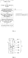
- the system includes a fuel tank 1, a pre-filter 2, a fuel transfer pump 3, a fine filter 4, and a fuel injection pump 5.
- the fuel tank 1 is sequentially connected to the pre-filter 2, the fuel transfer pump 3, the fine filter 4, and the fuel injection pump 5 via an oil pipe 7.
- a fuel return port of the fuel injection pump 5 is also connected to the fuel tank 1 via the oil pipe 7.
- a gas discharging device 6 discharging fuel gas is arranged between the fuel transfer pump 3 and the fuel injection pump 5.
- An outlet of the gas discharging device 6 communicates with the fuel tank 1 via the oil pipe.
- a fixing mount 42 is arranged at an oil feeding port 41 of the fine filter 4. The gas discharging device 6 is fixed to the fine filter 4 via the fixing mount 42.
- the gas discharging device 6 and the fixing mount 42 are connected tightly through screw threads to fix the gas discharging device 6 to the fine filter 4. An influence of vibration of an engine during normal operation on the gas discharging device 6 can be effectively avoided. Normal service life of the gas discharging device 6 can be prolonged, and operation stability can be increased.
- the gas discharging device 6 may also be connected to two segments of connecting oil pipe 7 between an oil outlet of the fuel transfer pump 3 and an oil inlet of the fuel injection pump 5 via a three-way joint.
- the gas discharging device 6 is a one-way valve.
- the gas discharging device 6 includes a valve body 61, a valve body inlet 66 provided at one end of the valve body 61, and a gas discharging hole 62 provided on a side surface of the valve body 61.
- the valve body inlet 66 communicates with the fixing mount 42.
- the gas discharging hole 62 communicates with the fuel tank 1 via the oil pipe.
- a hole diameter of the gas discharging hole 62 is 0.5 mm.
- the hole diameter of the gas discharging hole 62 is preset according to the above formula with the experimental data before installing the gas discharging device 6, and the hole diameter of the gas discharging hole 62 is verified according to the above formula with the experimental data measured after installing the gas discharging device 6, so that the gas discharging device 6 can ensure sufficient gas discharging capability, and avoid excessive fuel flowing back to the fuel tank 1 via the gas discharging hole, thereby not affecting the normal operation of the engine.
- An opening pressure of the one-way valve is 5 bar.
- the opening pressure of the one-way valve may also be 1.5 bar or 2 bar or 3 bar or 4 bar or 6 bar.
- the hole diameter of the gas discharging hole 62 may also be 0.2 mm or 0.7 mm or 1 mm or 1.5 mm or 2 mm or 3 mm.
- Table 1 Number of tests Gas discharging hole (mm) start drag (s) Axial pressure setup start (s) Axial pressure closed (s) Ignition time (s) Activation time (s) Axial pressure setup to delay (s) Axial pressure setup to closed loop (s) successful ignition (s) 0 7.014 8.794 9.324 9.364 2.66 1.78 0.53 0.31 1 0.5 4.838 5.666 6.066 6.186 1.619 0.828 0.4 0.271 2 0.5 5.926 6.836 7.307 7.467 1.77 0.91 0.471 0.229
Landscapes
- Engineering & Computer Science (AREA)
- Chemical & Material Sciences (AREA)
- Combustion & Propulsion (AREA)
- Mechanical Engineering (AREA)
- General Engineering & Computer Science (AREA)
- Fuel-Injection Apparatus (AREA)
- Lubrication Details And Ventilation Of Internal Combustion Engines (AREA)
Abstract
Description
- The present invention relates to the field of engines, in particular, to a care-free activation system of an electrically controlled common rail engine.
- In an existing electrically controlled common rail engine, a fuel system is an important factor affecting activation performance thereof. At present, an existing common rail system mainly improves the activation performance of an engine by optimizing system components and optimizing a complete machine layout design. However, these methods cannot completely solve the problem of long activation time or failure in activation. An electronic fuel transfer pump is added to some engines to speed up gas discharging of an oil channel, so a purpose of speeding up the activation can be achieved, and complete machine costs may be increased. Meanwhile, it is not recognized in the prior art that presence of gas from a fuel transfer pump to a fuel injection pump affects the activation performance.
- The present invention is directed to a care-free activation system of an electrically controlled common rail engine, which can effectively increase activation performance of the engine.
- To this end, a care-free activation system of an electrically controlled common rail engine is provided. The system includes a fuel tank, a fuel transfer pump, a fine filter, and a fuel injection pump. A gas discharging device discharging fuel gas is arranged on an oil channel between an oil outlet of the fuel transfer pump and an oil inlet of the fuel injection pump. An outlet of the gas discharging device communicates with the fuel tank via an oil pipe.
- Preferably, the gas discharging device is a one-way valve.
- Preferably, an opening pressure of the gas discharging device is between 1.5 bar and 6 bar.
- Preferably, the gas discharging device includes a valve body, a valve body inlet provided at one end of the valve body, and a gas discharging hole provided on a side surface of the valve body. The valve body inlet communicates with the oil channel between the oil outlet of the fuel transfer pump and the fine filter. The gas discharging hole communicates with the fuel tank via the oil pipe. The hole diameter of the gas discharging hole is between 0.2 mm and 3 mm.
- Preferably, the hole diameter of the gas discharging hole is preliminarily determined according to a following formula and confirmed by test verification:

- Preferably, the gas discharging device is arranged on the fine filter.
- Preferably, a fixing mount is arranged at an oil feeding port on a filter mount of the fine filter, and the gas discharging device is fixed to the fine filter via the fixing mount.
- Compared with the prior art, the present invention has the following beneficial effects.
- In the present invention, by arranging the gas discharging device at the oil feeding port of the fine filter, air in the fine filter can be discharged via the gas discharging device, thereby implementing active gas discharging, and effectively increasing activation performance of the engine. Compared with a scheme adopting an electronic fuel transfer pump, the present invention is ingenious in structure and high in reliability, and effectively reduces costs due to no additional control system. Compared with a scheme without an electronic fuel transfer pump, the present invention can significantly increase activation speed of an engine.
-
-
Fig. 1 is a schematic structural view of the present invention. -
Fig. 2 is a structural block diagram of the present invention. -
Fig. 3 is a flowchart of a method in the present invention. -
Fig. 4 is a schematic structural view of a gas discharging device in the present invention. -
Fig. 5 is a schematic view of a structural relationship between a fine filter and a gas discharging device in the present invention. - The present invention is further described below with reference to embodiments, but does not constitute any limitation to the present invention, and any finite number of modifications made within the scope of the claims of the present invention are still within the scope of the claims of the present invention.
- As shown in
Fig. 1 to Fig. 5 , the present invention provides a care-free activation system of an electrically controlled common rail engine. The system includes afuel tank 1, a pre-filter 2, afuel transfer pump 3, afine filter 4, and afuel injection pump 5. Thefuel tank 1 is sequentially connected to the pre-filter 2, thefuel transfer pump 3, thefine filter 4, and thefuel injection pump 5 via anoil pipe 7. A fuel return port of thefuel injection pump 5 is also connected to thefuel tank 1 via theoil pipe 7. Agas discharging device 6 discharging fuel gas is arranged between thefuel transfer pump 3 and thefuel injection pump 5. An outlet of thegas discharging device 6 communicates with thefuel tank 1 via the oil pipe. Afixing mount 42 is arranged at anoil feeding port 41 of thefine filter 4. Thegas discharging device 6 is fixed to thefine filter 4 via thefixing mount 42. - In the present embodiment, the
gas discharging device 6 and thefixing mount 42 are connected tightly through screw threads to fix thegas discharging device 6 to thefine filter 4. An influence of vibration of an engine during normal operation on thegas discharging device 6 can be effectively avoided. Normal service life of thegas discharging device 6 can be prolonged, and operation stability can be increased. In addition, thegas discharging device 6 may also be connected to two segments of connectingoil pipe 7 between an oil outlet of thefuel transfer pump 3 and an oil inlet of thefuel injection pump 5 via a three-way joint. - The
gas discharging device 6 is a one-way valve. Thegas discharging device 6 includes avalve body 61, avalve body inlet 66 provided at one end of thevalve body 61, and agas discharging hole 62 provided on a side surface of thevalve body 61. Thevalve body inlet 66 communicates with thefixing mount 42. Thegas discharging hole 62 communicates with thefuel tank 1 via the oil pipe. A hole diameter of thegas discharging hole 62 is 0.5 mm. - The hole diameter of the
gas discharging hole 62 is preliminarily determined according to a following formula and confirmed by test verification:
gas discharging hole 62, P is a pressure in thefine filter 4, V is a volume of thefine filter 4, a is a cross-sectional area of thegas discharging hole 62, and v is a flow velocity of fuel. - In the present embodiment, when calculating the hole diameter of the
gas discharging hole 62, the hole diameter of thegas discharging hole 62 is preset according to the above formula with the experimental data before installing thegas discharging device 6, and the hole diameter of thegas discharging hole 62 is verified according to the above formula with the experimental data measured after installing thegas discharging device 6, so that thegas discharging device 6 can ensure sufficient gas discharging capability, and avoid excessive fuel flowing back to thefuel tank 1 via the gas discharging hole, thereby not affecting the normal operation of the engine. - An opening pressure of the one-way valve is 5 bar. In addition, the opening pressure of the one-way valve may also be 1.5 bar or 2 bar or 3 bar or 4 bar or 6 bar.
- In addition, the hole diameter of the
gas discharging hole 62 may also be 0.2 mm or 0.7 mm or 1 mm or 1.5 mm or 2 mm or 3 mm. - An operation process of the present embodiment is as follows: after the engine is activated to operate, fuel in the
fuel tank 1 sequentially passes through the pre-filter 2, thefuel transfer pump 3 and thefine filter 4 via theoil pipe 7 and is then injected to thefuel injection pump 5. When there is air in thefine filter 4, pressure in thefine filter 4 is increased to push away a sealingsteel ball 65 of the one-way valve 6, and the air in thefine filter 4 and part of the fuel enter the one-way valve 6 through thevalve body inlet 66, pass through thegas discharging hole 62 in the side surface of thevalve body 61 and are discharged back into thefuel tank 1 via theoil pipe 7; and when the air in thefine filter 4 is discharged, the intensity of pressure is lower than the pressure of apressure limiting spring 63 against the sealingsteel ball 65, such that the sealingsteel ball 65 is in contact with thevalve body inlet 66, the one-way valve 6 is closed, and the air in thefine filter 4 can be reduced, thereby shortening the next activation time of the engine and achieving a purpose of smooth activation. - The effect contrast between the present invention and the existing activation system of the electrically controlled common rail engine is shown in Table 1.
Table 1 Number of tests Gas discharging hole (mm) start drag (s) Axial pressure setup start (s) Axial pressure closed (s) Ignition time (s) Activation time (s) Axial pressure setup to delay (s) Axial pressure setup to closed loop (s) successful ignition (s) 0 7.014 8.794 9.324 9.364 2.66 1.78 0.53 0.31 1 0.5 4.838 5.666 6.066 6.186 1.619 0.828 0.4 0.271 2 0.5 5.926 6.836 7.307 7.467 1.77 0.91 0.471 0.229 - It can be seen from Table 1 that the activation time of the present invention is significantly and effectively shortened compared to the activation time of the existing electrically controlled common rail engine, thereby effectively increasing activation performance of the engine.
- The above is only a preferred implementation of the present invention, and it should be noted that those skilled in the art can make various modifications and improvements without departing from the structure of the present invention, and such modifications and improvements do not affect the implementation effects and applicability of the present invention.
Claims (7)
- A care-free activation system of an electrically controlled common rail engine, comprising a fuel tank (1), a fuel transfer pump (3), a fine filter (4), and a fuel injection pump (5), characterized in that, a gas discharging device (6) discharging fuel gas is arranged on an oil channel between an oil outlet of the fuel transfer pump (3) and an oil inlet of the fuel injection pump (5), and an outlet of the gas discharging device (6) communicates with the fuel tank (1) via an oil pipe.
- The care-free activation system of the electrically controlled common rail engine according to claim 1, characterized in that, the gas discharging device (6) is a one-way valve.
- The care-free activation system of the electrically controlled common rail engine according to claim 2, characterized in that, an opening pressure of the gas discharging device (6) is between 1.5 bar and 6 bar.
- The care-free activation system of the electrically controlled common rail engine according to claim 2, characterized in that, the gas discharging device (6) comprises a valve body (61), a valve body inlet (66) provided at one end of the valve body (61), and a gas discharging hole (62) provided on a side surface of the valve body (61), the valve body inlet (66) communicating with the oil channel between the oil outlet of the fuel transfer pump (3) and the fine filter (4), the gas discharging hole (62) communicating with the fuel tank (1) via the oil pipe, a hole diameter of the gas discharging hole (62) is between 0.2 mm and 3 mm.
- The care-free activation system of the electrically controlled common rail engine according to claim 4, characterized in that, the hole diameter of the gas discharging hole (62) is preliminarily determined according to a following formula and confirmed by test verification:

- The care-free activation system of the electrically controlled common rail engine according to claim 2, characterized in that, the gas discharging device (6) is arranged on the fine filter (4).
- The care-free activation system of the electrically controlled common rail engine according to claim 6, characterized in that, a fixing mount (42) is arranged at an oil feeding port (41) on a filter mount of the fine filter (4), and the gas discharging device (6) is fixed to the fine filter (4) via the fixing mount (42).
Applications Claiming Priority (2)
| Application Number | Priority Date | Filing Date | Title |
|---|---|---|---|
| CN201710088361.XA CN107061082A (en) | 2017-02-17 | 2017-02-17 | The carefree activation system of electric-controlled co-rail engine |
| PCT/CN2017/106273 WO2018149160A1 (en) | 2017-02-17 | 2017-10-23 | Activation method utilized in electrically controlled common rail engine |
Publications (2)
| Publication Number | Publication Date |
|---|---|
| EP3550135A1 true EP3550135A1 (en) | 2019-10-09 |
| EP3550135A4 EP3550135A4 (en) | 2019-12-04 |
Family
ID=59622744
Family Applications (1)
| Application Number | Title | Priority Date | Filing Date |
|---|---|---|---|
| EP17896851.7A Withdrawn EP3550135A4 (en) | 2017-02-17 | 2017-10-23 | Activation method utilized in electrically controlled common rail engine |
Country Status (4)
| Country | Link |
|---|---|
| US (1) | US20190331074A1 (en) |
| EP (1) | EP3550135A4 (en) |
| CN (1) | CN107061082A (en) |
| WO (1) | WO2018149160A1 (en) |
Families Citing this family (4)
| Publication number | Priority date | Publication date | Assignee | Title |
|---|---|---|---|---|
| CN106837642A (en) * | 2017-02-17 | 2017-06-13 | 广西玉柴机器股份有限公司 | A kind of electric-controlled co-rail engine quick start method |
| CN107061082A (en) * | 2017-02-17 | 2017-08-18 | 广西玉柴机器股份有限公司 | The carefree activation system of electric-controlled co-rail engine |
| CN111472905B (en) * | 2020-04-07 | 2025-08-15 | 三一重机有限公司 | Fuel system of rotary drilling rig, rotary drilling rig and control method of fuel system |
| CN117622496B (en) * | 2024-01-23 | 2024-06-04 | 西安爱生技术集团有限公司 | A UAV fuel system suitable for electronically controlled engines and a design method thereof |
Family Cites Families (22)
| Publication number | Priority date | Publication date | Assignee | Title |
|---|---|---|---|---|
| US5544483A (en) * | 1993-02-19 | 1996-08-13 | Volkswagen Ag | Internal combustion engine with a secondary air-fuel supply |
| CN100379974C (en) * | 2000-09-20 | 2008-04-09 | 三国株式会社 | Fuel supply device and fuel filter for the fuel supply device |
| US6959696B2 (en) * | 2002-04-12 | 2005-11-01 | Briggs & Stratton Corporation | Internal combustion engine evaporative emission control system |
| US7779818B2 (en) * | 2007-07-12 | 2010-08-24 | Caterpillar Inc. | System and method for priming a fluid system |
| US8186332B2 (en) * | 2009-07-20 | 2012-05-29 | Mann & Hummel Gmbh | Fluid filter with integrated temperature regulation |
| JP5786502B2 (en) * | 2011-07-05 | 2015-09-30 | 浜名湖電装株式会社 | Evaporative fuel purge device |
| JP5663624B2 (en) * | 2013-03-26 | 2015-02-04 | 株式会社ミツバ | Fuel supply device |
| JP6036575B2 (en) * | 2013-06-25 | 2016-11-30 | 京三電機株式会社 | Fuel filter device |
| CN103742322A (en) * | 2013-09-18 | 2014-04-23 | 任化一 | Automatic air exhausting device for diesel engine oil way |
| CN203822509U (en) * | 2014-04-30 | 2014-09-10 | 中国重汽集团济南动力有限公司 | Diesel engine oil circuit electric control air bleeding device |
| CN103953479A (en) * | 2014-04-30 | 2014-07-30 | 中国重汽集团济南动力有限公司 | Electrically controlled air discharging device for oil way of diesel engine |
| JP5921618B2 (en) * | 2014-08-08 | 2016-05-24 | ヤマハ発動機株式会社 | Fuel supply device, fuel supply method and ship propulsion device |
| US9611801B2 (en) * | 2014-12-15 | 2017-04-04 | Ford Global Technologies, Llc | Methods and systems for fixed and variable pressure fuel injection |
| CN204553029U (en) * | 2015-03-09 | 2015-08-12 | 广西华原过滤系统股份有限公司 | A kind of automatic vent fuel oil filtering system |
| US10774799B2 (en) * | 2015-03-25 | 2020-09-15 | Cd Patents, Llc | Fuel-air separator and improved air bleed system |
| CN204716436U (en) * | 2015-06-18 | 2015-10-21 | 常州市万航工矿设备有限公司 | Internal combustion locomotive oil supplying device |
| CN105156241A (en) * | 2015-08-24 | 2015-12-16 | 太仓澄天机械有限公司 | Diesel engine fuel oil air removal device |
| CN205955876U (en) * | 2016-07-04 | 2017-02-15 | 广西华原过滤系统股份有限公司 | Help improving novel diesel oil filter of engine cold start performance |
| CN205936908U (en) * | 2016-07-12 | 2017-02-08 | 潍柴动力股份有限公司 | Automatically controlled engine fuel oil system |
| CN206448893U (en) * | 2017-02-17 | 2017-08-29 | 广西玉柴机器股份有限公司 | The carefree activation system of electric-controlled co-rail engine |
| CN107061082A (en) * | 2017-02-17 | 2017-08-18 | 广西玉柴机器股份有限公司 | The carefree activation system of electric-controlled co-rail engine |
| CN106837642A (en) * | 2017-02-17 | 2017-06-13 | 广西玉柴机器股份有限公司 | A kind of electric-controlled co-rail engine quick start method |
-
2017
- 2017-02-17 CN CN201710088361.XA patent/CN107061082A/en active Pending
- 2017-10-23 WO PCT/CN2017/106273 patent/WO2018149160A1/en not_active Ceased
- 2017-10-23 US US16/468,294 patent/US20190331074A1/en not_active Abandoned
- 2017-10-23 EP EP17896851.7A patent/EP3550135A4/en not_active Withdrawn
Also Published As
| Publication number | Publication date |
|---|---|
| WO2018149160A1 (en) | 2018-08-23 |
| CN107061082A (en) | 2017-08-18 |
| US20190331074A1 (en) | 2019-10-31 |
| EP3550135A4 (en) | 2019-12-04 |
Similar Documents
| Publication | Publication Date | Title |
|---|---|---|
| EP3550137A1 (en) | Rapid activation method utilized in electrically controlled common rail engine | |
| EP3550135A1 (en) | Activation method utilized in electrically controlled common rail engine | |
| US7617991B2 (en) | Injector fuel filter with built-in orifice for flow restriction | |
| US7527043B2 (en) | Liquid fuel system with anti-drainback valve and engine using same | |
| WO2006074833A1 (en) | Exhaust gas subsequent processing method and method therefor | |
| CN105526025A (en) | Evaporation fuel purge system | |
| US8931261B2 (en) | Apparatus, system, and method for diverting fluid | |
| JPH0427757A (en) | Water injection diesel engine | |
| CN104421074A (en) | Fuel delivery system including integrated check valve | |
| JP5804639B2 (en) | Fuel leak detection method and common rail fuel injection control device | |
| JPH1082351A (en) | Control method and control device for internal combustion engine | |
| CN206448893U (en) | The carefree activation system of electric-controlled co-rail engine | |
| CN110242387A (en) | Hydrocarbon spraying system and its control method | |
| DE102005037150A1 (en) | Device for metering a reducing agent | |
| WO2010072443A1 (en) | Device for feeding metered fuel | |
| JP2015086812A (en) | Failure diagnosis system of common rail system, and failure diagnosis method therein | |
| CN108119274B (en) | Fuel supply pump in fuel injection system | |
| US8042522B2 (en) | Fuel rail vent system | |
| JP2014224519A (en) | Fuel press-feeding control method and common rail type fuel injection control device | |
| CN111520238A (en) | Gas fuel supply pressure control device | |
| DE102014226476A1 (en) | Shut-off valve for a dosing module and method for its diagnosis | |
| KR100230848B1 (en) | Filer damper | |
| DE102013212734A1 (en) | Method for operating a hydraulic conveying and dosing system | |
| CN201148930Y (en) | Oil circuit device of locomotive jet engine | |
| KR20020077763A (en) | Injector of vehicle using gas fuel and apparatus for supplying fuel using thereof |
Legal Events
| Date | Code | Title | Description |
|---|---|---|---|
| PUAI | Public reference made under article 153(3) epc to a published international application that has entered the european phase |
Free format text: ORIGINAL CODE: 0009012 |
|
| 17P | Request for examination filed |
Effective date: 20190703 |
|
| AK | Designated contracting states |
Kind code of ref document: A1 Designated state(s): AL AT BE BG CH CY CZ DE DK EE ES FI FR GB GR HR HU IE IS IT LI LT LU LV MC MK MT NL NO PL PT RO RS SE SI SK SM TR |
|
| AX | Request for extension of the european patent |
Extension state: BA ME |
|
| A4 | Supplementary search report drawn up and despatched |
Effective date: 20191106 |
|
| RIC1 | Information provided on ipc code assigned before grant |
Ipc: F16K 15/00 20060101ALI20191030BHEP Ipc: F02M 37/20 20060101AFI20191030BHEP Ipc: F02M 37/04 20060101ALN20191030BHEP Ipc: F02M 37/00 20060101ALI20191030BHEP Ipc: F02M 37/54 20190101ALI20191030BHEP Ipc: F02M 37/32 20190101ALI20191030BHEP |
|
| STAA | Information on the status of an ep patent application or granted ep patent |
Free format text: STATUS: THE APPLICATION HAS BEEN WITHDRAWN |
|
| 18W | Application withdrawn |
Effective date: 20200414 |