EP3549901A1 - Schubmaststapler - Google Patents
Schubmaststapler Download PDFInfo
- Publication number
- EP3549901A1 EP3549901A1 EP19160171.5A EP19160171A EP3549901A1 EP 3549901 A1 EP3549901 A1 EP 3549901A1 EP 19160171 A EP19160171 A EP 19160171A EP 3549901 A1 EP3549901 A1 EP 3549901A1
- Authority
- EP
- European Patent Office
- Prior art keywords
- attachment
- load
- mast
- sensor device
- linear actuator
- Prior art date
- Legal status (The legal status is an assumption and is not a legal conclusion. Google has not performed a legal analysis and makes no representation as to the accuracy of the status listed.)
- Granted
Links
Images

Classifications
-
- B—PERFORMING OPERATIONS; TRANSPORTING
- B66—HOISTING; LIFTING; HAULING
- B66F—HOISTING, LIFTING, HAULING OR PUSHING, NOT OTHERWISE PROVIDED FOR, e.g. DEVICES WHICH APPLY A LIFTING OR PUSHING FORCE DIRECTLY TO THE SURFACE OF A LOAD
- B66F17/00—Safety devices, e.g. for limiting or indicating lifting force
- B66F17/003—Safety devices, e.g. for limiting or indicating lifting force for fork-lift trucks
-
- B—PERFORMING OPERATIONS; TRANSPORTING
- B66—HOISTING; LIFTING; HAULING
- B66F—HOISTING, LIFTING, HAULING OR PUSHING, NOT OTHERWISE PROVIDED FOR, e.g. DEVICES WHICH APPLY A LIFTING OR PUSHING FORCE DIRECTLY TO THE SURFACE OF A LOAD
- B66F9/00—Devices for lifting or lowering bulky or heavy goods for loading or unloading purposes
- B66F9/06—Devices for lifting or lowering bulky or heavy goods for loading or unloading purposes movable, with their loads, on wheels or the like, e.g. fork-lift trucks
- B66F9/075—Constructional features or details
- B66F9/0755—Position control; Position detectors
-
- B—PERFORMING OPERATIONS; TRANSPORTING
- B66—HOISTING; LIFTING; HAULING
- B66F—HOISTING, LIFTING, HAULING OR PUSHING, NOT OTHERWISE PROVIDED FOR, e.g. DEVICES WHICH APPLY A LIFTING OR PUSHING FORCE DIRECTLY TO THE SURFACE OF A LOAD
- B66F9/00—Devices for lifting or lowering bulky or heavy goods for loading or unloading purposes
- B66F9/06—Devices for lifting or lowering bulky or heavy goods for loading or unloading purposes movable, with their loads, on wheels or the like, e.g. fork-lift trucks
- B66F9/075—Constructional features or details
- B66F9/08—Masts; Guides; Chains
- B66F9/10—Masts; Guides; Chains movable in a horizontal direction relative to truck
Definitions
- the invention relates to a reach truck with a two spaced apart in the vehicle transverse direction of the wheel arms, wherein a mast in the vehicle longitudinal direction by means of a linear actuator is slidably disposed between the two Radarmen, wherein on the mast, a fork carriage by means of a lifting drive is arranged lowered and raised, wherein on the fork carriage an attachment for handling a load is arranged.
- Reach trucks are equipped with a mast for stacking and storing transport goods (loads).
- a fork carriage is moved in the vertical direction, i. raised and lowered, over which the load in height and position is moved.
- the mast is displaced in the horizontal vehicle longitudinal direction, i. pushed forwards in the vehicle longitudinal direction or retracted to the rear.
- An attachment is arranged on the fork carriage for handling the load.
- the attachment is formed by a fork with two forks. With the attachment or on the forks, the load, for example by means of a pallet, recorded.
- Reach trucks may optionally have a sideshift device of the attachment, a so-called sideshifter, or the mast, a so-called Hubgerüstquerschub.
- a sideshift device of the attachment a so-called sideshifter, or the mast, a so-called Hubgerüstquerschub.
- the attachment can be adjusted laterally in the horizontal vehicle transverse direction.
- the side shift device a fine positioning of the attachment for receiving the load or for depositing the load, for example, on a shelf, performed.
- the lateral positioning of the attachment by means of the side sliding device must be performed in known reach trucks by the driver.
- Reach trucks may optionally have a so-called center transverse thrust of the mast or center side pusher of the attachment.
- center transverse thrust of the mast or center side slide of the attachment is on Pressing the mast transverse thrust or the side slide device of the attachment operated in the middle position. From the center position of the mast transverse thrust and the side sliding of the attachment in both directions of movement can travel the same way.
- Reach trucks may optionally be provided with a push / pull lock which prevents inadvertent lowering of the load received by the attachment to the wheel arms.
- the push / Senksperr worn is enabled or disabled depending on the Schubwegposition of the mast. In addition, the possibility of retraction of the mast is limited depending on the lifting height of the fork carriage.
- the push / Senksperr issued is designed such that the lowering of the attachment by means of the lifting drive between the two wheel arms is prevented (Senksperre), as long as the mast is retracted in a position between the two radar arms position in the vehicle longitudinal direction. As a result, wide loads during lowering can not accidentally be deposited on the wheel arms and become unstable.
- the driver can cancel the lowering lock of the push / lock locking device by pressing an acknowledge button.
- the attachment In order to be able to deposit a load handled with the attachment on the roadway, the attachment must be lowered to the lowering lock and then the mast extended in the vehicle longitudinal direction to the front end stop. Then the attachment can be lowered further and deposited the load on the road surface become.
- the push / Senksperr worn is also designed so that when fully extended in the vehicle longitudinal direction forward to the end mast lifting the attachment without Senksperre can be completely lowered, but then the retraction and thus the retraction of the mast to the rear by means of thrust drive is locked (thrust lock ).
- An essential component of a reach truck are the two wheel arms, in which or on which the mast in the vehicle longitudinal direction by means of Thrust drive is moved.
- the wheel arms are also a potential hazard, since a recorded or auf redesignde load can collide with the radar arms.
- the standard loading and unloading process of a load with a reach truck involves pulling the load between the wheel arms to move it.
- both when lowering the attachment and when retracting the mast there is a risk of collision of the attachment or the load with a radar arm or two radar arms when the attachment or the load is not centrally positioned in the vehicle transverse direction or wider than the clear dimension between the two radar arms is.
- attachments exceed the clear distance between the two arms, so that a complete lowering of the fork carriage is only possible with fully pushed out to the front mast.
- the present invention has for its object to provide a reach truck of the type mentioned, which also enables untrained drivers to avoid collisions of the load or the attachment with a radar arm or both radar arms and has an increased turnover performance.
- the reach truck has a sensor device with a handled by the attachment load and / or a protrusion of the load or the attachment is detected in the outer contour of the wheel arms inside, and the sensor device with a shear drive of the mast and the lifting drive of the fork carriage controlling device is in operative connection, wherein the control device is designed such that the thrust drive and the linear actuator are controlled in response to the sensor device that a movement of the linear actuator and the linear actuator are stopped such that a collision of the load and / or the attachment with a wheel arm or both arms is prevented.
- the invention is thus detected with the sensor device, whether the load and / or the attachment protrudes into the outer contour of the wheel arms and only in the event that the load and / or the attachment in the outer contour of the wheel arms protrudes into, ie the further lowering of the Attachment or the further retraction process of the mast would lead to a collision of the load or the attachment with a radar arm or two radar arms, the retraction movement of the mast by means of the thrust drive and the lowering movement of the attachment stopped by the lifting drive such that a collision of the load and / or of the attachment with a wheel arm or both arms is prevented.
- an assistance system is achieved, which effectively prevents a collision of the load or the attachment with a radar arms or both radar arms and with the inexperienced driver can safely prevent collisions of the load or the attachment with a radar arms or two radar arms. Furthermore, the lowering movement of the attachment or the retraction of the mast will only be terminated if this Movements would actually lead to a collision of the load or the attachment with a radar arm or two radar arms, so that the workflow is not interrupted
- the reach truck is provided with a push / Senksperr adopted the thrust drive and the linear actuator and controls the control device, the push / Senksperr recognized the thrust drive and the linear actuator, wherein the control device is designed such that the push / Senksperr worn in dependence is controlled by the sensor device.
- the control device is designed in such a way that the push / shut-off device is activated only when the load is handled by the sensor device and / or the load or attachment protrudes into the outer contour of a wheel arm or both wheel arms is detected.
- the push / Senksperr adopted thus limited only the lowering movement of the attachment or the withdrawal movement of the mast, when in fact the risk of collision of the load or the attachment with a radar arm or two radar arms. If no such risk of collision is detected by the sensor device, the push / lock locking device is deactivated, so that the attachment can be lowered without lowering lock and the mast can be withdrawn to the rear without a push lock.
- the control device is designed according to an alternative or additional embodiment of the invention such that the push / Senksperr worn is only deactivated if the sensor device not handled by the attachment load and / or no protrusion of the load or the attachment in the outer contour of a Radarms or both wheel arms is detected inside.
- the push / Senksperr worn can thus only be deactivated by the driver when there is no risk of collision of the load or the attachment with a wheel arm or both arms.
- the push / lock device is activated only when the sensor device detects a load handled by the attachment and / or a protrusion of the load or attachment into the outer contour of a wheel arm or both wheel arms, and can only be deactivated when the load is released Sensor means no load handled by the attachment and / or no protrusion of the load or the attachment is detected in the outer contour of a radar arm or both wheel arms inside.
- the control device controls a tilt drive of the mast and / or a side slide device of the attachment or the mast and / or an auxiliary hydraulic function of the attachment, such as a Zinkenverstellêt, wherein the control device is designed such that the tilt drive of the mast and / or the Sideshift device of the attachment or the mast and / or the auxiliary hydraulic function of the attachment are controlled in response to the sensor device such that movement of the tilting mechanism of the mast and / or the side sliding device of the attachment or the mast and / or the auxiliary hydraulic function of the attachment are stopped such that a collision of the load and / or the attachment with a wheel arm or both arms is prevented.
- the control device is designed such that the tilt drive of the mast and / or the Sideshift device of the attachment or the mast and / or the auxiliary hydraulic function of the attachment are controlled in response to the sensor device such that movement of the tilting mechanism of the mast and / or the side sliding device of the attachment or the mast and / or the auxiliary hydraulic function of the attachment are stopped such that a
- control device makes it possible for the control device to block or stop shifting, for example by actuating the tilt drive or the side shift device or the auxiliary hydraulic function, of a load or attachment located within the two wheel arms, which results in a collision of the load or of the attachment with a wheel arm or two radar arms.
- the sensor device can be designed as a load recognition sensor, for example as a pressure sensor for detecting the pressure in a lifting cylinder device of the lifting drive. If a load handled by the attachment is detected with the load detection sensor, this can be detected by the control device as a potential risk of collision of the load with a Radarm or both radar arms are evaluated and the movement of the linear actuator and the linear actuator are stopped so that a collision of the load with a wheel arm or both arms is prevented or the push / Senksperr adopted be activated.
- a load recognition sensor for example as a pressure sensor for detecting the pressure in a lifting cylinder device of the lifting drive.
- the sensor device can be designed as a sensor device monitoring the outer contour of the wheel arms. With such a sensor device can be detected in a simple manner, whether a load or the attachment protrudes into the outer contour of the wheel arms into it and thus a risk of collision of the load or the attachment with a wheel or both radar arms are detected.
- the sensor device may be designed as a line sensor that detects a line or as a surface sensor that detects a collision surface.
- the collision surfaces formed by the outer surfaces of the wheel arms can be easily monitored for possible collision with the load or the attachment.
- a line sensor detecting a line the spanning collision surface can be calculated from the process (lowering / retreating) of the load from the controller.
- area sensors the entire collision areas or partial areas thereof can be measured directly.
- the sensor device can be designed as an optical sensor, for example LED or laser, or as a distance sensor (1D, 2D or 3D) or as a switch or as an ultrasonic sensor or as an inductive sensor or as a capacitive sensor or as a magnetic sensor or as a camera.
- an optical sensor for example LED or laser
- the invention achieves a number of advantages: Inexperienced drivers are assisted in handling a load, since stopping the implement lowering operation or the mast back-off operation is automatically terminated by the controller before the load or implement collides with either or both of the radar arms. Even experienced drivers are supported in the workflow and can work faster by the deceleration of the lowering movement of the attachment and the return movement of the mast initiated by the controller so and carried out that the attachment or the load comes with a close but safe distance to the outer contour of the wheel arms to a halt, so that the driver as long as possible fast lowering movements of the attachment and retracting movements of the mast can perform.
- the driver is assisted in such a way that the recorded load can be lowered optimally deep without causing a collision with one or both of the wheel arms. This enables an optimally low load center of the reach truck with the load picked up and safe operation.
- the operator In a reach truck having a midway thrust of the mast of the attachment, the operator is assisted in load handling with asymmetrical implement contours or asymmetric load contours or wider contours of the implement or wider contours of the load than the clearance between the wheel arms with the control device collisions of the load or the attachment with a wheel arm or both radar arms are avoided.
- the driver of the reach truck is supported by the control device during load handling of a load located within the two wheel arms, since the movement of a side sliding device and / or a tilt drive and / or the operation of an auxiliary hydraulic function of the attachment, such as a Zinkenverstell réelles be limited such that collisions of the load with one or both radar arms are avoided by the control device.
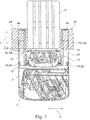
- an inventive reach truck 1 which has a vehicle frame 2, the two spaced in the vehicle transverse direction Q spaced wheel arms 2a, 2b has. At the front ends of the wheel arms 2a, 2b are each a load wheel 4a, 4b arranged. In the vehicle longitudinal direction L spaced from the load wheels 4a, 4b, a steerable drive wheel 5 is arranged on the vehicle frame 2.
- the reach truck 1 is supported by the drive wheel 5 and the two load wheels 4a, 4b on a roadway.
- a mast 10 in the vehicle longitudinal direction L is displaceably arranged by means of a linear actuator not shown.
- the mast 10 is arranged on a thrust carriage 11, which is displaceable by means of the thrust drive to the wheel arms 2a, 2b in the vehicle longitudinal direction L.
- a fork carriage 12 On the mast 10, a fork carriage 12 is lowered by means of a lifting drive 13 and arranged liftable. On the fork carriage 12, an attachment 15 for handling a load is arranged. In the illustrated embodiment, the attachment 15 is formed by two forks 16a, 16b. The load is in the illustrated embodiment of FIG. 1 formed by a pallet P.
- the mast 10 can be arranged tiltable about a horizontal tilt axis N, by which the mast 10 by means of a tilt drive not shown to the front V and back H are inclined can.
- the tilting axis N is arranged in the illustrated embodiment between the slide carriage 11 and the mast 10.
- a side sliding device may be provided, with which the attachment 15 or the mast 10 in the vehicle transverse direction Q can be moved.
- the attachment 15 can be moved relative to the mast 10 in the vehicle transverse direction Q or the mast 10 are moved relative to the thrust carriage 11 in the vehicle transverse direction Q with the side slide.
- the mast 10 in a fully retracted by the thrust drive to the rear position. Starting from the illustrated position, the mast 10 can be moved by means of the thrust drive in the horizontal vehicle longitudinal direction to the front.
- FIG. 1 a pallet P located on the forks 16a, 16b is shown.
- the pallet P has an outer contour and width which is smaller than the clear width between the two wheel arms 2a, 2b, so that the pallet P between the two wheel arms 2a, 2b can be lowered onto the road surface.
- the reach truck 1 is provided with a push / Senksperr worn which prevents unintentional lowering of the attachment 15 received with the load (pallet P) on the wheel arms 2a, 2b.
- the push / Senksperr worn is enabled or disabled depending on the Schubwegposition the mast 10.
- the retraction of the mast 10 is limited depending on the lifting height of the fork carriage 12.
- the push / Senksperr immunity is designed such that the lowering of the attachment 15 by means of the lifting drive between the two wheel arms 2a, 2b is prevented (Senksperre), as long as the mast 10 is retracted by means of the linear actuator in a located between the two wheel arms 2a, 2b position in the vehicle longitudinal direction L.
- the push / Senksperr worn is further designed such that when fully extended in the vehicle longitudinal direction L forward to the end stop mast 10 the attachment 15 can be completely lowered by means of the lifting drive without Senksperre, but then the retraction and thus the retraction of the mast 10 is locked to the rear by means of the thrust drive (thrust lock).
- the reach truck 1 has a sensor device 20 with which a load handled by the attachment 15 and / or a protrusion of the load or attachment 15 into the outer contour of the wheel arms 2a, 2b is detected.
- the sensor device 20 is in operative connection with a control device 21 controlling the linear actuator and the linear actuator, in particular an electronic control device.
- the control device 21 is configured such that the thrust drive and the lifting drive are controlled in such a manner in dependence on the sensor device 20 that a movement of the thrust drive and the lifting drive are stopped such that a collision of the load and / or the attachment 15 with a Radarm 2a 2b or both wheel arms 2a, 2b is prevented.
- the control device 21 controls for this purpose the push / Senksperr issued of the linear actuator and the linear actuator and is designed such that the push / Senksperr issued is driven in response to the sensor device 20.
- the sensor device 20 is preferably designed as a sensor device 22 monitoring the outer contour of the wheel arms 2a, 2b.
- the sensor device 22 can be designed as a line sensor or area sensor.
- interference contour a protrusion of the load or the attachment 15 in the contour of the wheel arms 2a, 2b detected in. This detection is referred to below as interference contour.
- the detection of a Störachir ie the detection of a protrusion of the load or the attachment 15 in the contour of the wheel arms 2a, 2b in by collision surfaces KF on the Radarmen 2a, 2b, in the FIGS. 1 and 2 are clarified with the hatching, is on possible interference contours, ie a projecting into the collision surface KF load or projecting into the collision surface KF protruding attachment 15, is monitored.
- the detection of the interference contour by means of the sensor device 20 is further processed in the control device 21 and connected to the function of the push / Senksperr unpleasant.
- this compound can be so pronounced that the push / Senksperr worn is only activated when a disturbing contour is present, and the push / Senksperr worn can only be switched off when no interference contour is present.
- the control device 21 is in this case designed such that the push / Senksperr worn is only activated when the sensor device 20 handled by the attachment 15 load and / or a protrusion of the load or the attachment 15 in the collision surface KF and thus in the outer contour the wheel arms 2a, 2b is detected inside. If as in the FIG. 1 is shown, the load (pallet P) is smaller than the clear width between the two wheel arms 2a, 2b and thus the load (pallet P) does not project into the collision surfaces KF and thus into the outer contour of the wheel arms 2a, 2b, is the Push / Senksperr issued deactivated so that the attachment 15 can be completely lowered with the load thereon, although the mast 10 is by means of the thrust drive in the retracted position.
- the control device 21 ends the lowering movement of the fork carriage 12 and / or the backward movement of the mast 10 such that there is no collision of the attachment 15 or the load thus received with the wheel arms 2a, 2b.
- the control device 21 initiates a corresponding braking operation of the lowering movement of the attachment 15 and / or the return movement of the lifting frame 10, so that the attachment 15 or the load is stopped before contact with the outer contour of the wheel arms 2a, 2b.
- collision surfaces KF greater than the outer contour (width and height) of the wheel arms 2a, 2b.
- control device 21 is designed such that the push / Senksperr worn is only deactivated if the sensor device 20 is not handled by the attachment 15 load and / or no protrusion of the load or the attachment 15 in the collision surface KF and thus in the outer contour the wheel arms 2a, 2b is detected inside.
- the control device 20 may further control the tilt drive of the mast 10 and / or a side slide device of the attachment 15 or the mast 10 and / or an optional auxiliary hydraulic function of the attachment 15, such as a Zinkenverstell réelle, and be designed such that the tilt drive of the mast 10 and / or the side slide device of the attachment 15 or the mast 10 and / or the auxiliary hydraulic function of the attachment are controlled in response to the sensor device 20 such that a movement of the tilt drive of the mast 10 and / or the side slide device of the attachment 15 or the mast 10 and / or or the auxiliary hydraulic function of the attachment are stopped such that a collision of the load and / or the attachment 15 with a wheel arm 2a or 2b or two Radarmen 2a, 2b is prevented.
- the control device 21 thus blocks the shifting of a load by means of the tilt drive and / or the side slide device and / or the additional hydraulic function of the attachment 15 within both wheel arms 2a, 2b, which could lead to a collision with the wheel arms 2a, 2b.
- a load detection can alternatively also be used.
- the sensor device can be designed as a load recognition sensor, for example as a pressure sensor for detecting the pressure in a lifting cylinder device of the lifting drive.
- each recorded load is then detected as a disturbing contour and, when a recorded load is detected, the push / shut-off locking device is activated. If there is no load on the attachment, the push / pull locking device is deactivated accordingly.
Landscapes
- Engineering & Computer Science (AREA)
- Structural Engineering (AREA)
- Transportation (AREA)
- Life Sciences & Earth Sciences (AREA)
- Geology (AREA)
- Mechanical Engineering (AREA)
- Civil Engineering (AREA)
- Forklifts And Lifting Vehicles (AREA)
Abstract
Description
- Die Erfindung betrifft einen Schubmaststapler mit einem zwei in Fahrzeugquerrichtung voneinander beabstandet angeordneten Radarmen, wobei zwischen den beiden Radarmen ein Hubgerüst in Fahrzeuglängsrichtung mittels eines Schubantriebs verschiebbar angeordnet ist, wobei an dem Hubgerüst ein Gabelträger mittels eines Hubantriebs absenkbar und anhebbar angeordnet ist, wobei an dem Gabelträger ein Anbaugerät zum Handhaben einer Last angeordnet ist.
- Schubmaststapler sind mit einem Hubgerüst zum Stapeln und Einlagern von Transportgütern (Lasten) ausgestattet. Über das Hubgerüst wird ein Gabelträger in vertikaler Richtung verschoben, d.h. angehoben und abgesenkt, über den die Last in Höhe und Position bewegt wird. Bei einem Schubmaststapler wird beim Stapelvorgang der Last zusätzlich das Hubgerüst in horizontaler Fahrzeuglängsrichtung verschoben, d.h. in Fahrzeuglängsrichtung nach Vorne ausgeschoben bzw. nach Hinten zurückgezogen. Am Gabelträger ist für die Handhabung der Last ein Anbaugerät angeordnet. In der Regel ist das Anbaugerät von einer Lastgabel mit zwei Gabelzinken gebildet. Mit dem Anbaugerät bzw. auf den Gabelzinken wird die Last, beispielsweise mittels einer Palette, aufgenommen.
- Schubmaststapler können optional eine Seitenschiebereinrichtung des Anbaugeräts, einen sogenannten Seitenschieber, oder des Hubgerüstes, einen sogenannten Hubgerüstquerschub, aufweisen. Über die Seitenschiebereinrichtung kann das Anbaugerät in horizontaler Fahrzeugquerrichtung seitlich verstellt werden. Mit der Seitenschiebereinrichtung kann eine Feinpositionierung des Anbaugeräts zur Aufnahme der Last bzw. zum Absetzen der Last, beispielsweise in einem Regal, durchgeführt werden. Die seitliche Positionierung des Anbaugeräts mittels der Seitenschiebereinrichtung muss bei bekannten Schubmaststaplern vom Fahrer durchgeführt werden.
- Schubmaststapler können optional einen sogenannten Mittequerschub des Hubgerüstes bzw. Mitteseitenschieber des Anbaugeräts aufweisen. Mit dem Mittequerschub des Hubgerüstes bzw. Mitteseitenschieber des Anbaugeräts wird auf Tastendruck der Hubgerüstquerschub bzw. die Seitenschiebereinrichtung des Anbaugeräts in die Mittelposition betätigt. Von der Mittelposition aus kann der Hubgerüstquerschub bzw. die Seitenschiebereinrichtung des Anbaugeräts in beide Bewegungsrichtungen den gleichen Weg zurücklegen.
- Schubmaststapler können optional mit einer Schub-/Senksperreinrichtung versehen sein, die ein unbeabsichtigtes Absenken der mit dem Anbaugerät aufgenommenen Last auf die Radarme verhindert. Die Schub-/Senksperreinrichtung wird in Abhängigkeit der Schubwegposition des Hubgerüstes freigegebene oder gesperrt. Zusätzlich wird die Rückzugmöglichkeit des Hubgerüstes eingeschränkt in Abhängigkeit der Hubhöhe des Gabelträgers. Die Schub-/Senksperreinrichtung ist derart ausgeführt, dass das Absenken des Anbaugeräts mittels des Hubantriebs zwischen die beiden Radarme verhindert wird (Senksperre), solange das Hubgerüst in einer zwischen den beiden Radarmen befindlichen Position in Fahrzeuglängsrichtung eingefahren ist. Dadurch können breite Lasten beim Senken nicht versehentlich auf die Radarme abgelegt und instabil werden. Der Fahrer kann die Senksperre der Schub-/Senksperreinrichtung durch Betätigen einer Quittiertaste aufheben. Um eine mit dem Anbaugerät gehandhabte Last auf der Fahrbahn absetzen zu können, muss das Anbaugerät bis zur Senksperre abgesenkt werden und anschließend das Hubgerüst in Fahrzeuglängsrichtung nach Vorne bis zu einem Endanschlag ausgefahren werden Anschließend kann das Anbaugerät weiter abgesenkt werden und die Last auf die Fahrbahnoberfläche abgesetzt werden. Die Schub-/Senksperreinrichtung ist weiterhin derart ausgeführt, dass bei vollständig in Fahrzeuglängsrichtung nach Vorne bis zum Endanschlag ausgefahrenem Hubgerüst das Anbaugerät ohne Senksperre ganz abgesenkt werden kann, jedoch dann das Einfahren und somit das Zurückziehen des Hubgerüstes nach Hinten mittels des Schubantriebs gesperrt ist (Schubsperre). Dadurch wird verhindert, dass eine mit dem Anbaugerät aufgenommene Last beim Zurückziehen des Hubgerüstes durch Kontakt mit den Radarmen von dem Anbaugeräts, beispielswiese den Gabelzinken, abgestreift wird. Der Fahrer muss zum Zurückziehen des Hubgerüstes zuerst die Last wieder auf eine Hubhöhe oberhalb der Radarme anhheben oder die Schubsperre der Schub-/Senksperreinrichtung durch Quittieren aufheben.
- Ein wesentlicher Bestandteil eines Schubmaststaplers sind die beiden Radarme, in denen bzw. auf denen das Hubgerüst in Fahrzeuglängsrichtung mittels des Schubantriebs verschoben wird. Die Radarme stellen jedoch auch ein Gefahrenpotential dar, da eine aufgenommene bzw. aufzunehmende Last mit den Radarmen kollidieren kann. Zum Standardein- und auslagerprozess einer Last mit einem Schubmaststapler gehört es, dass die Last zwischen die Radarme zurückgezogen wird, um diese zu verfahren. Sowohl beim Absenken des Anbaugeräts als auch beim Zurückziehen des Hubgerüstes besteht jedoch die Gefahr der Kollision des Anbaugeräts oder der Last mit einem Radarm oder beiden Radarmen, wenn das Anbaugerät bzw. die Last nicht in Fahrzeugquerrichtung mittig positioniert ist oder aber breiter als das lichte Maß zwischen den beiden Radarmen ist. Oftmals Überschreiten Anbaugeräten das lichte Maß zwischen den beiden Radarmen, so dass ein vollständiges Absenken des Gabelträgers nur mit vollständig nach Vorne ausgeschobenem Hubgerüst möglich ist.
- Bei bekannten Schubmaststaplern beenden bei der Handhabung einer Last geübte Fahrer den Senkvorgang des Anbaugeräts und den Rückzugvorgang des Hubgerüstes nach hinten bevor es zu einer Kollision der Last bzw. des Anbaugeräts mit einem Radarm oder beiden Radarmen kommt.
- Bei bekannten Schubmaststaplern, die mit einer Seitenschiebereinrichtung des Anbaugeräts oder des Hubgerüstes versehen sind, können geübte Fahrer die Anbaugerätekontur und die Kontur der Ladung mit der Seitenschiebereinrichtung gezielt zwischen den beiden Radarmen positionieren, um eine Kollision der Last bzw. des Anbaugeräts mit einem Radarm oder beiden Radarmen zu vermeiden.
- Bei bekannten Schubmaststaplern, die einen Mittequerschub des Hubgerüstes bzw. Mitteseitenschieber des Anbaugeräts aufweisen, kann zwar die Last oder das Anbaugerät in der Mitte symmetrisch zwischen den beiden Radarmen positioniert werden. Bei einer breiten Last, einem breiten Anbaugerät oder einer asymmetrischen Kontur des Anbaugeräts oder einer asymmetrischen Kontur der Last kann jedoch weiterhin eine Kollision der Last bzw. des Anbaugeräts mit einem Radarm oder beiden Radarmen auftreten.
- Bei bekannten Schubmaststapler, die mit einer Schub-/Senksperreinrichtung versehen sind, verhindert die Schub-/Senksperreinrichtung immer das unachtsame Absenken des Anbaugeräts oder unachtsame Zurückziehen des Hubgerüstes ohne zu berücksichtigen, ob es beim Senken des Anbaugeräts oder dem Zurückziehen des Hubgerüstes durch die aufgenommene Last oder das Anbaugerät tatsächlich zu einer Kollision mit einem Radarm oder beiden Radarmen kommen würde. Dadurch kommt es zu einer Unterbrechung des Arbeitsflusses.
- Der vorliegenden Erfindung liegt die Aufgabe zugrunde, einen Schubmaststapler der eingangs genannten Gattung zur Verfügung zu stellen, der es auch ungeübten Fahrern ermöglicht, Kollisionen der Last bzw. des Anbaugeräts mit einem Radarm oder beiden Radarmen zu vermeiden und der eine erhöhte Umschlagsleistung aufweist.
- Diese Aufgabe wird erfindungsgemäß dadurch gelöst, dass der Schubmaststapler eine Sensoreinrichtung aufweist, mit der eine von dem Anbaugerät gehandhabte Last und/oder ein Überstehen der Last oder des Anbaugeräts in die Außenkontur der Radarme hinein detektiert wird, und die Sensoreinrichtung mit einer den Schubantrieb des Hubgerüstes und den Hubantrieb des Gabelträgers steuernden Steuereinrichtung in Wirkverbindung steht, wobei die Steuereinrichtung derart ausgebildet ist, dass der Schubantriebs und der Hubantrieb derart in Abhängigkeit von der Sensoreinrichtung angesteuert werden, dass eine Bewegung des Schubantriebs und des Hubantriebs derart gestoppt werden, dass eine Kollision der Last und/oder des Anbaugeräts mit einem Radarm oder beiden Radarmen verhindert wird.
- Erfindungsgemäß wird somit mit der Sensoreinrichtung detektiert, ob die Last und/oder das Anbaugerät in die Außenkontur der Radarme hinein übersteht und nur für den Fall, dass die Last und/oder das Anbaugerät in die Außenkontur der Radarme hinein übersteht, d.h. der weitere Senkvorgang des Anbaugeräts oder der weitere Rückzugvorgang des Hubgerüstes zu einer Kollision der Last oder des Anbaugeräts mit einem Radarm oder beiden Radarmen führen würde, die Rückzugbewegung des Hubgerüstes mittels des Schubantriebs und die Senkenbewegung des Anbaugeräts mittels des Hubantriebs derart gestoppt, dass eine Kollision der Last und/oder des Anbaugeräts mit einem Radarm oder beiden Radarmen verhindert wird. Dadurch wird ein Assistenzsystem erzielt, das wirksam eine Kollision der Last bzw. des Anbaugeräts mit einem Radarme oder beiden Radarmen verhindert und mit dem auch ungeübte Fahrer sicher Kollisionen der Last bzw. des Anbaugeräts mit einem Radarme oder beiden Radarmen verhindert können. Weiterhin wird die Senkenbewegung des Anbaugeräts oder das Zurückziehen des Hubgerüstes nur dann beendet, wenn diese Bewegungen tatsächlich zu einer Kollision der Last bzw. des Anbaugeräts mit einem Radarm oder beiden Radarmen führen würden, so dass der Arbeitsfluss nicht unterbrochen wird
- Gemäß einer Weiterbildung der Erfindung ist der Schubmaststapler mit einer Schub-/Senksperreinrichtung des Schubantriebs und des Hubantriebs versehen und steuert die Steuereinrichtung die Schub-/Senksperreinrichtung des Schubantriebs und des Hubantriebs, wobei die Steuereinrichtung derart ausgebildet ist, dass die Schub-/Senksperreinrichtung in Abhängigkeit von der Sensoreinrichtung angesteuert wird. Dadurch wird es auf einfache Weise möglich, die Schub-/Senksperreinrichtung situationsabhängig nur dann zu aktivieren, wenn es beim Senken des Anbaugeräts oder dem Zurückziehen des Hubgerüstes durch die aufgenommene Last oder das Anbaugerät tatsächlich zu einer Kollision mit einem Radarm oder beiden Radarmen kommen würde. Dadurch können Unterbrechung des Arbeitsflusses verhindert werden.
- Die Steuereinrichtung ist gemäß einer Ausgestaltungsform der Erfindung derart ausgebildet, dass die Schub-/Senksperreinrichtung nur aktiviert wird, wenn von der Sensoreinrichtung eine von dem Anbaugerät gehandhabte Last und/oder ein Überstehen der Last oder des Anbaugeräts in die Außenkontur eines Radarms oder beider Radarme hinein detektiert wird. Die Schub-/Senksperreinrichtung begrenzt somit nur dann die Senkenbewegung des Anbaugeräts oder die Rückzugsbewegung des Hubgerüstes, wenn tatsächlich die Gefahr einer Kollision der Last oder das Anbaugeräts mit einem Radarm oder beiden Radarmen besteht. Wird von der Sensoreinrichtung keine derartige Kollisionsgefahr detektiert, ist die Schub-/Senksperreinrichtung deaktiviert, so dass das Anbaugeräts ohne Senksperre abgesenkt werden kann und das Hubgerüst ohne Schubsperre nach Hinten zurückgezogen werden kann.
- Die Steuereinrichtung ist gemäß einer alternativen oder zusätzlichen Ausgestaltungsform der Erfindung derart ausgebildet, dass die Schub-/Senksperreinrichtung nur deaktivierbar ist, wenn von der Sensoreinrichtung keine von dem Anbaugerät gehandhabte Last und/oder kein Überstehen der Last oder des Anbaugeräts in die Außenkontur eines Radarms oder beider Radarme hinein detektiert wird. Die Schub-/Senksperreinrichtung kann somit nur dann vom Fahrer deaktiviert werden, wenn keine Gefahr einer Kollision der Last oder das Anbaugeräts mit einem Radarm oder beiden Radarmen besteht.
- Es ist auch eine Kombination beider Maßnahmen möglich, d.h. die Schub-/Senksperreinrichtung wird nur aktiviert, wenn von der Sensoreinrichtung eine von dem Anbaugerät gehandhabte Last und/oder ein Überstehen der Last oder des Anbaugeräts in die Außenkontur eines Radarms oder beider Radarme hinein detektiert wird, und kann nur deaktiviert werden, wenn von der Sensoreinrichtung keine von dem Anbaugerät gehandhabte Last und/oder kein Überstehen der Last oder des Anbaugeräts in die Außenkontur eines Radarms oder beider Radarme hinein detektiert wird.
- Gemäß einer Weiterbildung der Erfindung steuert die Steuereinrichtung einen Neigeantrieb des Hubgerüstes und/oder eine Seitenschiebereinrichtung des Anbaugeräts oder des Hubgerüstes und/oder eine Zusatzhydraulikfunktion des Anbaugeräts, beispielsweise ein Zinkenverstellgerät, wobei die Steuereinrichtung derart ausgebildet ist, dass der Neigeantrieb des Hubgerüstes und/oder die Seitenschiebereinrichtung des Anbaugeräts oder des Hubgerüstes und/oder die Zusatzhydraulikfunktion des Anbaugeräts derart in Abhängigkeit von der Sensoreinrichtung angesteuert werden, dass eine Bewegung des Neigeantriebs des Hubgerüstes und/oder der Seitenschiebereinrichtung des Anbaugeräts oder des Hubgerüstes und/oder der Zusatzhydraulikfunktion des Anbaugeräts derart gestoppt werden, dass eine Kollision der Last und/oder des Anbaugeräts mit einem Radarm oder beiden Radarmen verhindert wird. Dies ermöglicht es, dass die Steuereinrichtung das Verschieben, beispielsweise durch Betätigen des Neigeantriebs oder der Seitenschiebereinrichtung oder der Zusatzhydraulikfunktion, einer innerhalb der beiden Radarme befindlichen Last bzw. Anbaugeräts sperrt bzw. beendet, welches zu einer Kollision der Last bzw. des Anbaugeräts mit einem Radarm oder beiden Radarmen führen würde.
- Die Sensoreinrichtung kann gemäß einer Ausgestaltungsform der Erfindung als Lasterkennungssensor ausgebildet sein, beispielsweise als Drucksensor zur Erfassung des Drucks in einer Hubzylindereinrichtung des Hubantriebs. Sofern mit dem Lasterkennungssensor eine von dem Anbaugerät gehandhabte Last detektiert wird, kann dies von der Steuereinrichtung als potentielle Kollisionsgefahr der Last mit einem Radarm oder beiden Radarmen gewertet werden und die Bewegung des Schubantriebs und des Hubantriebs derart gestoppt werden, dass eine Kollision der Last mit einem Radarm oder beiden Radarmen verhindert wird oder die Schub-/Senksperreinrichtung aktiviert werden.
- Die Sensoreinrichtung kann gemäß einer Ausgestaltungsform der Erfindung als eine die Außenkontur der Radarme überwachende Sensorvorrichtung ausgebildet sein. Mit einer derartigen Sensorvorrichtung kann auf einfache Weise detektiert werden, ob eine Last oder das Anbaugerät in die Außenkontur der Radarme hinein übersteht und somit eine Kollisionsgefahr der Last oder des Anbaugeräts mit einem Radarm oder beiden Radarmen detektiert werden.
- Die Sensorvorrichtung kann als Liniensensor, der eine Linie detektiert, oder als Flächensensor ausgebildet sein, der eine Kollisionsfläche detektiert. Mit derartigen Sensorvorrichtungen können auf einfache Weise die Kollisionsflächen, die von den Außenflächen der Radarme gebildet sind, auf mögliche Kollision mit der Last oder dem Anbaugerät überwacht werden. Mit einem Liniensensor, der eine Linie detektiert, kann die sich aufspannende Kollisionsfläche aus dem Verfahren (Senken/Zurückziehen) der Last von der Steuereinrichtung berechnet werden. Mit Flächensensoren können die gesamten Kollisionsflächen oder Teilflächen davon direkt gemessen werden.
- Die Sensorvorrichtung kann als optischer Sensor, beispielsweise LED oder Laser, oder als Abstandssensor (1D, 2D oder 3D) oder als Schalter oder als Ultraschallsensor oder als induktiver Sensor oder als kapazitiver Sensor oder als magnetischer Sensor oder als Kamera ausgebildet sein.
- Mit der Erfindung werden eine Reihe von Vorteilen erzielt:
Ungeübte Fahrer werden bei der Handhabung einer Last assistiert, da das Beenden des Senkvorgangs des Anbaugeräts oder des Rückschubvorgangs des Hubgerüstes automatisch von der Steuereinrichtung beendet wird, bevor es zu einer Kollision der Last oder des Anbaugeräts mit einem oder beiden Radarmen kommt. Auch geübte Fahrer werden im Arbeitsablauf unterstützt und können schneller arbeiten, indem der Abbremsvorgang der Senkenbewegung des Anbaugeräts und der Rückschubbewegung des Hubgerüstes von der Steuereinrichtung derart eingeleitet und durchgeführt wird, dass das Anbaugerät bzw. die Last mit knappem aber sicherem Abstand zur Außenkontur der Radarme zum Stehen kommt, so dass der Fahrer möglichst lange schnelle Senkenbewegungen des Anbaugeräts und Rückzugsbewegungen des Hubgerüstes ausführen kann. - Zusätzlich wird der Fahrer dahingehend unterstützt, dass die aufgenommene Last optimal tief, ohne eine Kollision mit einem oder beiden Radarmen hervorzurufen, abgesenkt werden kann. Dieses ermöglicht einen optimal tiefen Lastschwerpunkt des Schubmaststaplers mit aufgenommener Last und einen sicheren Betrieb.
- Bei einem Schubmaststapler mit einer Seitenschiebereinrichtung des Anbaugeräts oder des Hubgerüstes können ungeübte Fahrer und auch geübte Fahrer mit schwereinsehbaren Lasten überprüft werden, ob die Last bzw. das Anbaugerät innerhalb der Außenkontur der Radarme positioniert ist.
- Bei einem Schubmaststapler, der einen Mittequerschub des Hubgerüstes bzw. Mitteseitenschieber des Anbaugeräts aufweist, wird der Fahrer beim Lasthandling mit asymmetrischen Anbaugerätekonturen oder asymmetrischen Lastkonturen oder breiteren Konturen des Anbaugeräts oder breiteren Konturen der Last, als die lichte Weite zwischen den Radarmen hergibt, unterstützt, da mit der Steuereinrichtung Kollisionen der Last oder des Anbaugeräts mit einem Radarm oder beiden Radarmen vermieden werden.
- Bei einem Schubmaststapler, der eine Schub-/Senksperreinrichtung aufweist, wird beim Lasthandling von Lastkonturen, die kleiner sind als die lichte Weite zwischen den beiden Radarmen, der Fahrer von der Steuereinrichtung unterstützt, da von der Steuereinrichtung bei derartigen Lasten, bei denen keine Kollisionsgefahr mit den Radarmen besteht, die Schub-/Senksperreinrichtung deaktiviert ist, so dass das Anbaugerät ohne Senksperre abgesenkt werden kann und das Hubgerüst ohne Schubsperre nach Hinten zurückgezogen werden kann. Unterbrechungen des Arbeitsflusses werden somit vermieden, so dass eine erhöhte Umschlagsleistung des Flurförderzeugs ermöglicht wird.
- Zusätzlich wird der Fahrer des Schubmaststaplers von der Steuereinrichtung unterstützt beim Lasthandling einer innerhalb der beiden Radarme befindlichen Last, da von der Steuereinrichtung die Verfahrbewegungen einer Seitenschiebereinrichtung und/oder eines Neigeantriebs und/oder die Betätigung einer Zusatzhydraulikfunktion des Anbaugeräts, beispielsweise eines Zinkenverstellgeräts, derart begrenzt werden, dass Kollisionen der Last mit einem oder beiden Radarmen vermieden werden.
- Weitere Vorteile und Einzelheiten der Erfindung werden anhand des in den schematischen Figuren dargestellten Ausführungsbeispiels näher erläutert. Hierbei zeigt
- Figur 1
- ein erfindungsgemäßer Schubmaststapler in einer Draufsicht und
- Figur 2
- eine Seitenansicht des Schubmaststaplers der
Figur 1 ohne Last. - In den
Figuren 1 und2 ist ein erfindungsgemäßer Schubmaststapler 1 dargestellt, der einen Fahrzeugrahmen 2 aufweist, der zwei in Fahrzeugquerrichtung Q voneinander beabstandet angeordneten Radarme 2a, 2b aufweist. An den vorderen Enden der Radarme 2a, 2b ist jeweils ein Lastrad 4a, 4b angeordnet. In Fahrzeuglängsrichtung L beabstandet von den Lasträdern 4a, 4b ist an dem Fahrzeugrahmen 2 ein lenkbares Antriebsrad 5 angeordnet. Der Schubmaststapler 1 stützt sich mit dem Antriebsrad 5 und den beiden Lasträdern 4a, 4b auf einer Fahrbahn ab. - Zwischen den beiden Radarmen 2a, 2b ist ein Hubgerüst 10 in Fahrzeuglängsrichtung L mittels eines nicht näher dargestellten Schubantriebs verschiebbar angeordnet. Hierzu ist das Hubgerüst 10 an einem Schubschlitten 11 angeordnet, der mittels des Schubantriebs an den Radarmen 2a, 2b in Fahrzeuglängsrichtung L verschiebbar ist.
- An dem Hubgerüst 10 ist ein Gabelträger 12 mittels eines Hubantriebs 13 absenkbar und anhebbar angeordnet ist. An dem Gabelträger 12 ist ein Anbaugerät 15 zum Handhaben einer Last angeordnet. Im dargestellten Ausführungsbeispiel ist das Anbaugerät 15 von zwei Gabelzinken 16a, 16b gebildet. Die Last ist im dargestellten Ausführungsbeispiel der
Figur 1 von einer Palette P gebildet - Weiterhin kann bei dem Schubmaststapler 1 das Hubgerüst 10 um eine horizontale Neigeachse N neigbar angeordnet sein, um die das Hubgerüst 10 mittels eines nicht näher dargestellten Neigeantriebs nach Vorne V und nach hinten H geneigt werden kann. Die Neigeachse N ist im dargestellten Ausführungsbeispiel zwischen dem Schubschlitten 11 und dem Hubgerüst 10 angeordnet.
- Weiterhin kann bei dem Schubmaststapler 1 eine Seitenschiebereinrichtung vorgesehen sein, mit dem das Anbaugerät 15 oder das Hubgerüst 10 in Fahrzeugquerrichtung Q verschoben werden kann. Hierzu kann mit der Seitenschiebereinrichtung das Anbaugerät 15 relativ zum Hubgerüst 10 in Fahrzeugquerrichtung Q verschoben werden oder das Hubgerüst 10 relativ zum dem Schubschlitten 11 in Fahrzeugquerrichtung Q verschoben werden.
- In den
Figuren 1 und2 befindet sich das Hubgerüst 10 in einer vollständig mittels des Schubantriebs nach Hinten zurückgezogenen Position. Ausgehend von der dargestellten Position kann das Hubgerüst 10 mittels des Schubantriebs in horizontaler Fahrzeuglängsrichtung nach Vorne verschoben werden. - In den
Figuren 1 und2 befindet sich der Gabelträger 12 mit dem Anbaugerät 15 in einer vollständig abgesenkten Stellung. - In der
Figur 1 ist eine auf den Gabelzinken 16a, 16b befindliche Palette P dargestellt. Die Palette P hat eine Außenkontur und Breite, die geringer als die lichte Weite zwischen den beiden Radarmen 2a, 2b ist, so dass die Palette P zwischen den beiden Radarmen 2a, 2b auf die Fahrbahnoberfläche abgesenkt werden kann. - Der Schubmaststapler 1 ist mit einer Schub-/Senksperreinrichtung versehen, die ein unbeabsichtigtes Absenken der mit dem Anbaugerät 15 aufgenommenen Last (Palette P) auf die Radarme 2a, 2b verhindert. Die Schub-/Senksperreinrichtung wird in Abhängigkeit der Schubwegposition des Hubgerüstes 10 freigegebene oder gesperrt. Zusätzlich wird die Rückzugmöglichkeit des Hubgerüstes 10 eingeschränkt in Abhängigkeit der Hubhöhe des Gabelträgers 12. Die Schub-/Senksperreinrichtung ist derart ausgeführt, dass das Absenken des Anbaugeräts 15 mittels des Hubantriebs zwischen die beiden Radarme 2a, 2b verhindert wird (Senksperre), solange das Hubgerüst 10 mittels des Schubantriebs in einer zwischen den beiden Radarmen 2a, 2b befindlichen Position in Fahrzeuglängsrichtung L eingefahren ist. Die Schub-/Senksperreinrichtung ist weiterhin derart ausgeführt, dass bei vollständig in Fahrzeuglängsrichtung L nach Vorne bis zum Endanschlag ausgefahrenem Hubgerüst 10 das Anbaugerät 15 mittels des Hubantriebs ohne Senksperre ganz abgesenkt werden kann, jedoch dann das Einfahren und somit das Zurückziehen des Hubgerüstes 10 nach Hinten mittels des Schubantriebs gesperrt ist (Schubsperre).
- Erfindungsgemäß weist der Schubmaststapler 1 eine Sensoreinrichtung 20 auf, mit der eine von dem Anbaugerät 15 gehandhabte Last und/oder ein Überstehen der Last oder des Anbaugeräts 15 in die Außenkontur der Radarme 2a, 2b hinein detektiert wird. Die Sensoreinrichtung 20 steht mit einer den Schubantrieb und den Hubantrieb steuernden Steuereinrichtung 21, insbesondere einer elektronischen Steuereinrichtung, in Wirkverbindung. Die Steuereinrichtung 21 ist derart ausgebildet, dass der Schubantriebs und der Hubantrieb derart in Abhängigkeit von der Sensoreinrichtung 20 angesteuert werden, dass eine Bewegung des Schubantriebs und des Hubantriebs derart gestoppt werden, dass eine Kollision der Last und/oder des Anbaugeräts 15 mit einem Radarm 2a bzw. 2b oder beiden Radarmen 2a, 2b verhindert wird.
- Die Steuereinrichtung 21 steuert hierzu die Schub-/Senksperreinrichtung des Schubantriebs und des Hubantriebs und ist derart ausgebildet, dass die Schub-/Senksperreinrichtung in Abhängigkeit von der Sensoreinrichtung 20 angesteuert wird.
- Die Sensoreinrichtung 20 ist bevorzugt als eine die Außenkontur der Radarme 2a, 2b überwachende Sensorvorrichtung 22 ausgebildet. Die Sensorvorrichtung 22 kann als Liniensensor oder Flächensensor ausgebildet sein.
- Mit der Sensoreinrichtung 20 wird ein Überstehen der Last oder des Anbaugeräts 15 in die Kontur der Radarme 2a, 2b hinein detektiert. Diese Detektion wird im Folgenden als Störkontur bezeichnet.
- Von der Sensoreinrichtung 20 erfolgt die Erfassung einer Störkontor, d.h. die Detektion eines Überstehens der Last oder des Anbaugeräts 15 in die Kontur der Radarme 2a, 2b hinein, indem Kollisionsflächen KF an den Radarmen 2a, 2b, die in den
Figuren 1 und2 mit den Schraffuren verdeutlicht sind, auf mögliche Störkonturen, d.h. eine in die Kollisionsfläche KF hineinragende Last oder ein in die Kollisionsfläche KF hineinragende hineinragendes Anbaugerät 15, überwacht wird. - Die Detektion der Störkontur mittels der Sensoreinrichtung 20 wird in der Steuereinrichtung 21 weiterverarbeitet und mit der Funktion der Schub-/Senksperreinrichtung verbunden.
- Diese Verbindung kann derart ausgeprägt sein, dass die Schub-/Senksperreinrichtung nur aktiviert wird, wenn eine Störkontur vorhanden ist.
- Diese Verbindung kann alternativ oder zusätzlich derart ausgeprägt sein, dass die Schub-/Senksperreinrichtung nur abschaltbar ist, wenn keine Störkontur vorhanden ist.
- Zudem kann diese Verbindung derart ausgeprägt sein, dass die Schub-/Senksperreinrichtung nur aktiviert wird, wenn eine Störkontur vorhanden ist, und die Schub-/Senksperreinrichtung nur abschaltbar ist, wenn keine Störkontur vorhanden ist.
- Die Steuereinrichtung 21 ist hierbei derart ausgebildet, dass die Schub-/Senksperreinrichtung nur aktiviert wird, wenn von der Sensoreinrichtung 20 eine von dem Anbaugerät 15 gehandhabte Last und/oder ein Überstehen der Last oder des Anbaugeräts 15 in die Kollisionsfläche KF und somit in die Außenkontur der Radarme 2a, 2b hinein detektiert wird. Sofern wie in der
Figur 1 dargestellt ist, die Last (Palette P) kleiner als die lichte Weite zwischen den beiden Radarmen 2a, 2b ist und somit die Last (Palette P) nicht in die Kollisionsflächen KF und somit in die Außenkontur der Radarme 2a, 2b hinein übersteht, ist die Schub-/Senksperreinrichtung deaktiviert, so dass das Anbaugerät 15 mit der darauf befindlichen Last vollständig abgesenkt werden kann, obwohl sich das Hubgerüst 10 mittels des Schubantriebs in der zurückgezogen Stellung befindet. Sofern eine Last oder das Anbaugerät 15 beim Senken mittels des Hubantriebs oder beim Zurückziehen des Hubgerüstes 10 mittels des Schubantriebs in die Kollisionsfläche KF und somit in die Außenkontur einer oder beider Radarme 2a, 2b hineinragt, beendet die Steuereinrichtung 21 die Senkenbewegung des Gabelträgers 12 und/oder die Rückschubbewegung des Hubgerüstes 10 derart, dass es zu keiner Kollision des Anbaugeräts 15 bzw. der damit aufgenommenen Last mit den Radarmen 2a, 2b kommt. Die Steuereinrichtung 21 leitet hierzu einen entsprechenden Abbremsvorgang der Senkenbewegung des Anbaugeräts 15 und/oder der Rückschubbewegung des Hubgerüstes 10 ein, so dass das Anbaugerät 15 oder die Last vor Kontakt mit der Außenkontur der Radarme 2a, 2b gestoppt werden. Hierzu sind die von der Sensoreinrichtung 20 überwachten Kollisionsflächen KF größer als die Außenkontur (Breite und Höhe) der Radarme 2a, 2b. - Weiterhin ist die Steuereinrichtung 21 derart ausgebildet, dass die Schub-/Senksperreinrichtung nur deaktivierbar ist, wenn von der Sensoreinrichtung 20 keine von dem Anbaugerät 15 gehandhabte Last und/oder kein Überstehen der Last oder des Anbaugeräts 15 in die Kollisionsfläche KF und somit in die Außenkontur der Radarme 2a, 2b hinein detektiert wird.
- Die Steuereinrichtung 20 kann weiterhin den Neigeantrieb des Hubgerüstes 10 und/oder eine Seitenschiebereinrichtung des Anbaugeräts 15 oder des Hubgerüstes 10 und/oder eine gegebenenfalls vorhandene Zusatzhydraulikfunktion des Anbaugeräts 15, beispielsweise ein Zinkenverstellgerät, steuern und derart ausgebildet sein, dass der Neigeantrieb des Hubgerüstes 10 und/oder die Seitenschiebereinrichtung des Anbaugeräts 15 oder des Hubgerüstes 10 und/oder die Zusatzhydraulikfunktion des Anbaugeräts derart in Abhängigkeit von der Sensoreinrichtung 20 angesteuert werden, dass eine Bewegung des Neigeantriebs des Hubgerüstes 10 und/oder der Seitenschiebereinrichtung des Anbaugeräts 15 oder des Hubgerüstes 10 und/oder der Zusatzhydraulikfunktion des Anbaugeräts derart gestoppt werden, dass eine Kollision der Last und/oder des Anbaugeräts 15 mit einem Radarm 2a bzw. 2b oder beiden Radarmen 2a, 2b verhindert wird. Von der Steuereinrichtung 21 wird somit das Verschieben einer Last mittels des Neigeantriebs und/oder der Seitenschiebereinrichtung und/oder der Zusatzhydraulikfunktion des Anbaugeräts 15 innerhalb beiden Radarme 2a, 2b gesperrt, die zu einer Kollision mit der den Radarmen 2a, 2b führen könnte.
- Alternativ zu der die Kollisionsflächen KF überwachenden Sensoreinrichtung 20 kann alternativ auch eine Lasterkennung genutzt werden. Die Sensoreinrichtung kann hierzu als Lasterkennungssensor ausgebildet ist, beispielsweise als Drucksensor zur Erfassung des Drucks in einer Hubzylindereinrichtung des Hubantriebs. Hierbei wird dann jede aufgenommene Last als Störkontur detektiert und bei Ermittlung einer aufgenommenen Last die Schub-/Senksperreinrichtung aktiviert. Befindet sich keine Last auf dem Anbaugerät ist entsprechend die Schub-/Senksperreinrichtung deaktiviert.
Claims (8)
- Schubmaststapler (1) mit einem zwei in Fahrzeugquerrichtung (Q) voneinander beabstandet angeordneten Radarmen (2a, 2b), wobei zwischen den beiden Radarmen (2a, 2b) ein Hubgerüst (10) in Fahrzeuglängsrichtung (L) mittels eines Schubantriebs verschiebbar angeordnet ist, wobei an dem Hubgerüst (10) ein Gabelträger (12) mittels eines Hubantriebs absenkbar und anhebbar angeordnet ist, wobei an dem Gabelträger (12) ein Anbaugerät (15) zum Handhaben einer Last angeordnet ist, dadurch gekennzeichnet, dass der Schubmaststapler (1) eine Sensoreinrichtung (20) aufweist, mit der eine von dem Anbaugerät (15) gehandhabte Last und/oder ein Überstehen der Last oder des Anbaugeräts (15) in die Außenkontur der Radarme (2a; 2b) hinein detektiert wird, und die Sensoreinrichtung (20) mit einer den Schubantrieb und den Hubantrieb steuernden Steuereinrichtung (21) in Wirkverbindung steht, wobei die Steuereinrichtung (21) derart ausgebildet ist, dass der Schubantriebs und der Hubantrieb derart in Abhängigkeit von der Sensoreinrichtung (20) angesteuert werden, dass eine Bewegung des Schubantriebs und des Hubantriebs derart gestoppt werden, dass eine Kollision der Last und/oder des Anbaugeräts (15) mit einem Radarm (2a; 2b) oder beiden Radarmen (2a, 2b) verhindert wird.
- Schubmaststapler nach Anspruch 1, dadurch gekennzeichnet, dass der Schubmaststapler (1) mit einer Schub-/Senksperreinrichtung des Schubantriebs und des Hubantriebs versehen ist und die Steuereinrichtung (21) die Schub-/Senksperreinrichtung des Schubantriebs und des Hubantriebs steuert, wobei die Steuereinrichtung (21) derart ausgebildet ist, dass die Schub-/Senksperreinrichtung in Abhängigkeit von der Sensoreinrichtung (20) angesteuert wird.
- Schubmaststapler nach Anspruch 2, dadurch gekennzeichnet, dass die Steuereinrichtung (21) derart ausgebildet ist, dass die Schub-/Senksperreinrichtung nur aktiviert wird, wenn von der Sensoreinrichtung (20) eine von dem Anbaugerät (15) gehandhabte Last und/oder ein Überstehen der Last oder des Anbaugeräts (15) in die Außenkontur eines Radarms (2a; 2b) oder beider Radarme (2a, 2b) hinein detektiert wird.
- Schubmaststapler nach Anspruch 2 oder 3, dadurch gekennzeichnet, dass die Steuereinrichtung (21) derart ausgebildet ist, dass die Schub-/Senksperreinrichtung nur deaktivierbar ist, wenn von der Sensoreinrichtung (20) keine von dem Anbaugerät (15) gehandhabte Last und/oder kein Überstehen der Last oder des Anbaugeräts (15) in die Außenkontur eines Radarms (2a; 2b) oder beider Radarme (2a, 2b) hinein detektiert wird.
- Schubmaststapler nach einem der Ansprüche 1 bis 4, dadurch gekennzeichnet, dass die Steuereinrichtung (21) einen Neigeantrieb des Hubgerüstes und/oder eine Seitenschiebereinrichtung des Anbaugeräts (15) oder des Hubgerüstes (10) und/oder eine Zusatzhydraulikfunktion des Anbaugeräts (15) steuert, wobei die Steuereinrichtung (21) derart ausgebildet ist, dass der Neigeantrieb des Hubgerüstes (10) und/oder die Seitenschiebereinrichtung des Anbaugeräts (15) oder des Hubgerüstes (10) und/oder die Zusatzhydraulikfunktion des Anbaugeräts (15) derart in Abhängigkeit von der Sensoreinrichtung (20) angesteuert werden, dass eine Bewegung des Neigeantriebs des Hubgerüstes (10) und/oder der Seitenschiebereinrichtung des Anbaugeräts (15) oder des Hubgerüstes (10) und/oder der Zusatzhydraulikfunktion des Anbaugeräts (15) derart gestoppt werden, dass eine Kollision der Last und/oder des Anbaugeräts (15) mit einem Radarm (2a; 2b) oder beiden Radarmen (2a, 2b) verhindert wird.
- Schubmaststapler nach einem der Ansprüche 1 bis 5, dadurch gekennzeichnet, dass die Sensoreinrichtung (20) als Lasterkennungssensor ausgebildet ist, beispielsweise als Drucksensor zur Erfassung des Drucks in einer Hubzylindereinrichtung des Hubantriebs.
- Schubmaststapler nach einem der Ansprüche 1 bis 5, dadurch gekennzeichnet, dass die Sensoreinrichtung (20) als eine die Außenkontur der Radarme (2a, 2b) überwachende Sensorvorrichtung (22) ausgebildet ist.
- Schubmaststapler nach Anspruch 7, dadurch gekennzeichnet, dass die Sensorvorrichtung (22) als Liniensensor, der eine Linie detektiert, oder als Flächensensor ausgebildet ist, der eine Kollisionsfläche (KF) detektiert.
Applications Claiming Priority (2)
| Application Number | Priority Date | Filing Date | Title |
|---|---|---|---|
| DE102018105698 | 2018-03-13 | ||
| DE102018109869.3A DE102018109869A1 (de) | 2018-03-13 | 2018-04-24 | Schubmaststapler |
Publications (3)
| Publication Number | Publication Date |
|---|---|
| EP3549901A1 true EP3549901A1 (de) | 2019-10-09 |
| EP3549901A9 EP3549901A9 (de) | 2019-11-27 |
| EP3549901B1 EP3549901B1 (de) | 2021-01-06 |
Family
ID=67774099
Family Applications (1)
| Application Number | Title | Priority Date | Filing Date |
|---|---|---|---|
| EP19160171.5A Revoked EP3549901B1 (de) | 2018-03-13 | 2019-03-01 | Schubmaststapler |
Country Status (2)
| Country | Link |
|---|---|
| EP (1) | EP3549901B1 (de) |
| DE (1) | DE102018109869A1 (de) |
Cited By (1)
| Publication number | Priority date | Publication date | Assignee | Title |
|---|---|---|---|---|
| DE102018128406A1 (de) * | 2018-11-13 | 2020-05-14 | Jungheinrich Aktiengesellschaft | Flurförderzeug mit einem Notstoppsystem |
Families Citing this family (2)
| Publication number | Priority date | Publication date | Assignee | Title |
|---|---|---|---|---|
| CN113335940A (zh) * | 2021-05-20 | 2021-09-03 | 南京驭逡通信科技有限公司 | 一种智能制造的码垛工业机器人及其码垛方法 |
| DE102022132171A1 (de) * | 2022-12-05 | 2024-06-06 | Jungheinrich Aktiengesellschaft | Verfahren zur automatischen Prüfung von mindestens einem Schutzbereich an einem Flurförderzeug |
Citations (5)
| Publication number | Priority date | Publication date | Assignee | Title |
|---|---|---|---|---|
| EP1602621A2 (de) * | 2004-06-03 | 2005-12-07 | Still Gmbh | Flurförderzeug mit einer Sicherheitseinrichtung für ein Hubgerüst |
| DE102008008922A1 (de) * | 2008-02-13 | 2009-08-20 | Still Gmbh | Flurförderzeug mit Umgebungssensor |
| DE102008027701A1 (de) * | 2008-04-20 | 2009-10-29 | Still Gmbh | Steuerungsverfahren für Flurförderzeug |
| EP2518002A1 (de) | 2011-04-29 | 2012-10-31 | Jungheinrich Aktiengesellschaft | Flurförderzeug mit einer Endschalteranlage |
| WO2016043998A1 (en) | 2014-09-15 | 2016-03-24 | Crown Equipment Corporation | Lift truck with optical load sensing structure |
Family Cites Families (2)
| Publication number | Priority date | Publication date | Assignee | Title |
|---|---|---|---|---|
| AU5640490A (en) | 1989-12-04 | 1991-06-26 | Caterpillar Industrial Inc. | Apparatus and method for controllably positioning forks of a material handling vehicle |
| EP2168904B1 (de) | 2008-09-29 | 2011-11-30 | BT Products AB | Flurförderzeug mit automatisierter seitlicher Bewegung der Lastaufnamemittel |
-
2018
- 2018-04-24 DE DE102018109869.3A patent/DE102018109869A1/de active Pending
-
2019
- 2019-03-01 EP EP19160171.5A patent/EP3549901B1/de not_active Revoked
Patent Citations (5)
| Publication number | Priority date | Publication date | Assignee | Title |
|---|---|---|---|---|
| EP1602621A2 (de) * | 2004-06-03 | 2005-12-07 | Still Gmbh | Flurförderzeug mit einer Sicherheitseinrichtung für ein Hubgerüst |
| DE102008008922A1 (de) * | 2008-02-13 | 2009-08-20 | Still Gmbh | Flurförderzeug mit Umgebungssensor |
| DE102008027701A1 (de) * | 2008-04-20 | 2009-10-29 | Still Gmbh | Steuerungsverfahren für Flurförderzeug |
| EP2518002A1 (de) | 2011-04-29 | 2012-10-31 | Jungheinrich Aktiengesellschaft | Flurförderzeug mit einer Endschalteranlage |
| WO2016043998A1 (en) | 2014-09-15 | 2016-03-24 | Crown Equipment Corporation | Lift truck with optical load sensing structure |
Cited By (2)
| Publication number | Priority date | Publication date | Assignee | Title |
|---|---|---|---|---|
| DE102018128406A1 (de) * | 2018-11-13 | 2020-05-14 | Jungheinrich Aktiengesellschaft | Flurförderzeug mit einem Notstoppsystem |
| DE102018128406B4 (de) | 2018-11-13 | 2023-05-11 | Jungheinrich Aktiengesellschaft | Flurförderzeug mit einem Notstoppsystem |
Also Published As
| Publication number | Publication date |
|---|---|
| EP3549901B1 (de) | 2021-01-06 |
| DE102018109869A1 (de) | 2019-09-19 |
| EP3549901A9 (de) | 2019-11-27 |
Similar Documents
| Publication | Publication Date | Title |
|---|---|---|
| DE10305900C5 (de) | Stapler | |
| DE102008054085B4 (de) | Flurförderzeug | |
| EP3549901A9 (de) | Schubmaststapler | |
| EP4136049B1 (de) | Flurförderzeug mit lastaufnahmemitteln zur aufnahme von langgut | |
| EP3216744B1 (de) | Verfahren zur steuerung eines flurförderzeugs beim kommissionieren | |
| DE102016120117A1 (de) | Flurförderzeug mit einer Sensoreinrichtung zur Überwachung eines Umgebungsbereiches | |
| EP2805911A1 (de) | Flurförderzeug, insbesondere Kommissionierflurförderzeug mit einem anhebbaren und absenkbaren Fahrerstand | |
| WO2007012360A1 (de) | Fördersystem und verfahren zum gleichzeitigen transport von werkstücken und monteuren in einer fertigungslinie | |
| EP2518002A1 (de) | Flurförderzeug mit einer Endschalteranlage | |
| EP1447376B1 (de) | Schubmaststapler | |
| DE102008027701A1 (de) | Steuerungsverfahren für Flurförderzeug | |
| EP3272699B1 (de) | Regalstapler | |
| DE2017624A1 (de) | Lasttragwagen für schmale Gänge | |
| EP2848575B1 (de) | Steuerungsverfahren für Hubhöhenvorwahl eines Flurförderzeugs | |
| DE19956619B4 (de) | Lagersystem für Paletten | |
| EP4148002B1 (de) | Flurförderzeug | |
| EP3913455B1 (de) | Steuerung eines fahrzeugs über referenz- sensordaten | |
| EP3819255B1 (de) | Flurförderzeug, insbesondere schubmaststapler | |
| EP3770107B1 (de) | Flurförderzeug mit einer assistenzeinrichtung | |
| EP3514103A1 (de) | Flurförderzeug | |
| DE4112503A1 (de) | Notstoppeinrichtung fuer flurfoerderzeuge | |
| DE3214391A1 (de) | Selbstfahrendes fahrzeug | |
| DE102020107927A1 (de) | Transportsystem zum Kommissionieren | |
| DE102019131224A1 (de) | Moduleinheit zum Aufbau eines Routenzugs zum Transportieren von Gegenständen, Routenzug mit einer Anzahl von derartigen Moduleinheiten sowie Verfahren zum Betreiben einer solchen Moduleinheit | |
| DE102010053793B4 (de) | Steuersystem zur Führung eines Flurförderzeugs |
Legal Events
| Date | Code | Title | Description |
|---|---|---|---|
| PUAI | Public reference made under article 153(3) epc to a published international application that has entered the european phase |
Free format text: ORIGINAL CODE: 0009012 |
|
| STAA | Information on the status of an ep patent application or granted ep patent |
Free format text: STATUS: THE APPLICATION HAS BEEN PUBLISHED |
|
| AK | Designated contracting states |
Kind code of ref document: A1 Designated state(s): AL AT BE BG CH CY CZ DE DK EE ES FI FR GB GR HR HU IE IS IT LI LT LU LV MC MK MT NL NO PL PT RO RS SE SI SK SM TR |
|
| AX | Request for extension of the european patent |
Extension state: BA ME |
|
| TPAC | Observations filed by third parties |
Free format text: ORIGINAL CODE: EPIDOSNTIPA |
|
| STAA | Information on the status of an ep patent application or granted ep patent |
Free format text: STATUS: REQUEST FOR EXAMINATION WAS MADE |
|
| 17P | Request for examination filed |
Effective date: 20200326 |
|
| RBV | Designated contracting states (corrected) |
Designated state(s): AL AT BE BG CH CY CZ DE DK EE ES FI FR GB GR HR HU IE IS IT LI LT LU LV MC MK MT NL NO PL PT RO RS SE SI SK SM TR |
|
| GRAP | Despatch of communication of intention to grant a patent |
Free format text: ORIGINAL CODE: EPIDOSNIGR1 |
|
| STAA | Information on the status of an ep patent application or granted ep patent |
Free format text: STATUS: GRANT OF PATENT IS INTENDED |
|
| TPAC | Observations filed by third parties |
Free format text: ORIGINAL CODE: EPIDOSNTIPA |
|
| INTG | Intention to grant announced |
Effective date: 20200922 |
|
| GRAS | Grant fee paid |
Free format text: ORIGINAL CODE: EPIDOSNIGR3 |
|
| GRAA | (expected) grant |
Free format text: ORIGINAL CODE: 0009210 |
|
| STAA | Information on the status of an ep patent application or granted ep patent |
Free format text: STATUS: THE PATENT HAS BEEN GRANTED |
|
| AK | Designated contracting states |
Kind code of ref document: B1 Designated state(s): AL AT BE BG CH CY CZ DE DK EE ES FI FR GB GR HR HU IE IS IT LI LT LU LV MC MK MT NL NO PL PT RO RS SE SI SK SM TR |
|
| REG | Reference to a national code |
Ref country code: GB Ref legal event code: FG4D Free format text: NOT ENGLISH |
|
| REG | Reference to a national code |
Ref country code: AT Ref legal event code: REF Ref document number: 1352147 Country of ref document: AT Kind code of ref document: T Effective date: 20210115 Ref country code: CH Ref legal event code: EP |
|
| REG | Reference to a national code |
Ref country code: DE Ref legal event code: R096 Ref document number: 502019000625 Country of ref document: DE |
|
| REG | Reference to a national code |
Ref country code: IE Ref legal event code: FG4D Free format text: LANGUAGE OF EP DOCUMENT: GERMAN |
|
| REG | Reference to a national code |
Ref country code: SE Ref legal event code: TRGR |
|
| REG | Reference to a national code |
Ref country code: NL Ref legal event code: MP Effective date: 20210106 |
|
| REG | Reference to a national code |
Ref country code: LT Ref legal event code: MG9D |
|
| PG25 | Lapsed in a contracting state [announced via postgrant information from national office to epo] |
Ref country code: BG Free format text: LAPSE BECAUSE OF FAILURE TO SUBMIT A TRANSLATION OF THE DESCRIPTION OR TO PAY THE FEE WITHIN THE PRESCRIBED TIME-LIMIT Effective date: 20210406 Ref country code: HR Free format text: LAPSE BECAUSE OF FAILURE TO SUBMIT A TRANSLATION OF THE DESCRIPTION OR TO PAY THE FEE WITHIN THE PRESCRIBED TIME-LIMIT Effective date: 20210106 Ref country code: GR Free format text: LAPSE BECAUSE OF FAILURE TO SUBMIT A TRANSLATION OF THE DESCRIPTION OR TO PAY THE FEE WITHIN THE PRESCRIBED TIME-LIMIT Effective date: 20210407 Ref country code: FI Free format text: LAPSE BECAUSE OF FAILURE TO SUBMIT A TRANSLATION OF THE DESCRIPTION OR TO PAY THE FEE WITHIN THE PRESCRIBED TIME-LIMIT Effective date: 20210106 Ref country code: PT Free format text: LAPSE BECAUSE OF FAILURE TO SUBMIT A TRANSLATION OF THE DESCRIPTION OR TO PAY THE FEE WITHIN THE PRESCRIBED TIME-LIMIT Effective date: 20210506 Ref country code: NO Free format text: LAPSE BECAUSE OF FAILURE TO SUBMIT A TRANSLATION OF THE DESCRIPTION OR TO PAY THE FEE WITHIN THE PRESCRIBED TIME-LIMIT Effective date: 20210406 Ref country code: LT Free format text: LAPSE BECAUSE OF FAILURE TO SUBMIT A TRANSLATION OF THE DESCRIPTION OR TO PAY THE FEE WITHIN THE PRESCRIBED TIME-LIMIT Effective date: 20210106 |
|
| PG25 | Lapsed in a contracting state [announced via postgrant information from national office to epo] |
Ref country code: LV Free format text: LAPSE BECAUSE OF FAILURE TO SUBMIT A TRANSLATION OF THE DESCRIPTION OR TO PAY THE FEE WITHIN THE PRESCRIBED TIME-LIMIT Effective date: 20210106 Ref country code: PL Free format text: LAPSE BECAUSE OF FAILURE TO SUBMIT A TRANSLATION OF THE DESCRIPTION OR TO PAY THE FEE WITHIN THE PRESCRIBED TIME-LIMIT Effective date: 20210106 Ref country code: RS Free format text: LAPSE BECAUSE OF FAILURE TO SUBMIT A TRANSLATION OF THE DESCRIPTION OR TO PAY THE FEE WITHIN THE PRESCRIBED TIME-LIMIT Effective date: 20210106 |
|
| PG25 | Lapsed in a contracting state [announced via postgrant information from national office to epo] |
Ref country code: IS Free format text: LAPSE BECAUSE OF FAILURE TO SUBMIT A TRANSLATION OF THE DESCRIPTION OR TO PAY THE FEE WITHIN THE PRESCRIBED TIME-LIMIT Effective date: 20210506 |
|
| REG | Reference to a national code |
Ref country code: DE Ref legal event code: R026 Ref document number: 502019000625 Country of ref document: DE |
|
| PLBI | Opposition filed |
Free format text: ORIGINAL CODE: 0009260 |
|
| PLAX | Notice of opposition and request to file observation + time limit sent |
Free format text: ORIGINAL CODE: EPIDOSNOBS2 |
|
| PG25 | Lapsed in a contracting state [announced via postgrant information from national office to epo] |
Ref country code: SM Free format text: LAPSE BECAUSE OF FAILURE TO SUBMIT A TRANSLATION OF THE DESCRIPTION OR TO PAY THE FEE WITHIN THE PRESCRIBED TIME-LIMIT Effective date: 20210106 Ref country code: CZ Free format text: LAPSE BECAUSE OF FAILURE TO SUBMIT A TRANSLATION OF THE DESCRIPTION OR TO PAY THE FEE WITHIN THE PRESCRIBED TIME-LIMIT Effective date: 20210106 Ref country code: EE Free format text: LAPSE BECAUSE OF FAILURE TO SUBMIT A TRANSLATION OF THE DESCRIPTION OR TO PAY THE FEE WITHIN THE PRESCRIBED TIME-LIMIT Effective date: 20210106 Ref country code: MC Free format text: LAPSE BECAUSE OF FAILURE TO SUBMIT A TRANSLATION OF THE DESCRIPTION OR TO PAY THE FEE WITHIN THE PRESCRIBED TIME-LIMIT Effective date: 20210106 |
|
| 26 | Opposition filed |
Opponent name: CROWN EQUIPMENT CORPORATION Effective date: 20211006 Opponent name: JUNGHEINRICH AKTIENGESELLSCHAFT Effective date: 20211001 |
|
| PG25 | Lapsed in a contracting state [announced via postgrant information from national office to epo] |
Ref country code: DK Free format text: LAPSE BECAUSE OF FAILURE TO SUBMIT A TRANSLATION OF THE DESCRIPTION OR TO PAY THE FEE WITHIN THE PRESCRIBED TIME-LIMIT Effective date: 20210106 Ref country code: RO Free format text: LAPSE BECAUSE OF FAILURE TO SUBMIT A TRANSLATION OF THE DESCRIPTION OR TO PAY THE FEE WITHIN THE PRESCRIBED TIME-LIMIT Effective date: 20210106 Ref country code: SK Free format text: LAPSE BECAUSE OF FAILURE TO SUBMIT A TRANSLATION OF THE DESCRIPTION OR TO PAY THE FEE WITHIN THE PRESCRIBED TIME-LIMIT Effective date: 20210106 |
|
| REG | Reference to a national code |
Ref country code: BE Ref legal event code: MM Effective date: 20210331 |
|
| PG25 | Lapsed in a contracting state [announced via postgrant information from national office to epo] |
Ref country code: FR Free format text: LAPSE BECAUSE OF NON-PAYMENT OF DUE FEES Effective date: 20210306 Ref country code: IE Free format text: LAPSE BECAUSE OF NON-PAYMENT OF DUE FEES Effective date: 20210301 Ref country code: LU Free format text: LAPSE BECAUSE OF NON-PAYMENT OF DUE FEES Effective date: 20210301 Ref country code: AL Free format text: LAPSE BECAUSE OF FAILURE TO SUBMIT A TRANSLATION OF THE DESCRIPTION OR TO PAY THE FEE WITHIN THE PRESCRIBED TIME-LIMIT Effective date: 20210106 Ref country code: ES Free format text: LAPSE BECAUSE OF FAILURE TO SUBMIT A TRANSLATION OF THE DESCRIPTION OR TO PAY THE FEE WITHIN THE PRESCRIBED TIME-LIMIT Effective date: 20210106 |
|
| PLBB | Reply of patent proprietor to notice(s) of opposition received |
Free format text: ORIGINAL CODE: EPIDOSNOBS3 |
|
| PG25 | Lapsed in a contracting state [announced via postgrant information from national office to epo] |
Ref country code: SI Free format text: LAPSE BECAUSE OF FAILURE TO SUBMIT A TRANSLATION OF THE DESCRIPTION OR TO PAY THE FEE WITHIN THE PRESCRIBED TIME-LIMIT Effective date: 20210106 |
|
| PG25 | Lapsed in a contracting state [announced via postgrant information from national office to epo] |
Ref country code: IT Free format text: LAPSE BECAUSE OF FAILURE TO SUBMIT A TRANSLATION OF THE DESCRIPTION OR TO PAY THE FEE WITHIN THE PRESCRIBED TIME-LIMIT Effective date: 20210106 |
|
| PG25 | Lapsed in a contracting state [announced via postgrant information from national office to epo] |
Ref country code: IS Free format text: LAPSE BECAUSE OF FAILURE TO SUBMIT A TRANSLATION OF THE DESCRIPTION OR TO PAY THE FEE WITHIN THE PRESCRIBED TIME-LIMIT Effective date: 20210506 |
|
| PG25 | Lapsed in a contracting state [announced via postgrant information from national office to epo] |
Ref country code: BE Free format text: LAPSE BECAUSE OF NON-PAYMENT OF DUE FEES Effective date: 20210331 |
|
| REG | Reference to a national code |
Ref country code: CH Ref legal event code: PL |
|
| REG | Reference to a national code |
Ref country code: DE Ref legal event code: R103 Ref document number: 502019000625 Country of ref document: DE Ref country code: DE Ref legal event code: R064 Ref document number: 502019000625 Country of ref document: DE |
|
| PG25 | Lapsed in a contracting state [announced via postgrant information from national office to epo] |
Ref country code: LI Free format text: LAPSE BECAUSE OF NON-PAYMENT OF DUE FEES Effective date: 20220331 Ref country code: CH Free format text: LAPSE BECAUSE OF NON-PAYMENT OF DUE FEES Effective date: 20220331 |
|
| PGFP | Annual fee paid to national office [announced via postgrant information from national office to epo] |
Ref country code: SE Payment date: 20230315 Year of fee payment: 5 Ref country code: DE Payment date: 20230320 Year of fee payment: 5 |
|
| P01 | Opt-out of the competence of the unified patent court (upc) registered |
Effective date: 20230518 |
|
| PG25 | Lapsed in a contracting state [announced via postgrant information from national office to epo] |
Ref country code: NL Free format text: LAPSE BECAUSE OF NON-PAYMENT OF DUE FEES Effective date: 20210206 Ref country code: CY Free format text: LAPSE BECAUSE OF FAILURE TO SUBMIT A TRANSLATION OF THE DESCRIPTION OR TO PAY THE FEE WITHIN THE PRESCRIBED TIME-LIMIT Effective date: 20210106 |
|
| PG25 | Lapsed in a contracting state [announced via postgrant information from national office to epo] |
Ref country code: HU Free format text: LAPSE BECAUSE OF FAILURE TO SUBMIT A TRANSLATION OF THE DESCRIPTION OR TO PAY THE FEE WITHIN THE PRESCRIBED TIME-LIMIT; INVALID AB INITIO Effective date: 20190301 |
|
| RDAF | Communication despatched that patent is revoked |
Free format text: ORIGINAL CODE: EPIDOSNREV1 |
|
| GBPC | Gb: european patent ceased through non-payment of renewal fee |
Effective date: 20230301 |
|
| PG25 | Lapsed in a contracting state [announced via postgrant information from national office to epo] |
Ref country code: GB Free format text: LAPSE BECAUSE OF NON-PAYMENT OF DUE FEES Effective date: 20230301 |
|
| PG25 | Lapsed in a contracting state [announced via postgrant information from national office to epo] |
Ref country code: GB Free format text: LAPSE BECAUSE OF NON-PAYMENT OF DUE FEES Effective date: 20230301 |
|
| RDAG | Patent revoked |
Free format text: ORIGINAL CODE: 0009271 |
|
| STAA | Information on the status of an ep patent application or granted ep patent |
Free format text: STATUS: PATENT REVOKED |
|
| REG | Reference to a national code |
Ref country code: CH Ref legal event code: PL |
|
| 27W | Patent revoked |
Effective date: 20230113 |
|
| PG25 | Lapsed in a contracting state [announced via postgrant information from national office to epo] |
Ref country code: MK Free format text: LAPSE BECAUSE OF FAILURE TO SUBMIT A TRANSLATION OF THE DESCRIPTION OR TO PAY THE FEE WITHIN THE PRESCRIBED TIME-LIMIT Effective date: 20210106 |
|
| REG | Reference to a national code |
Ref country code: AT Ref legal event code: MA03 Ref document number: 1352147 Country of ref document: AT Kind code of ref document: T Effective date: 20230113 |
|
| REG | Reference to a national code |
Ref country code: SE Ref legal event code: ECNC |
|
| PG25 | Lapsed in a contracting state [announced via postgrant information from national office to epo] |
Ref country code: TR Free format text: LAPSE BECAUSE OF FAILURE TO SUBMIT A TRANSLATION OF THE DESCRIPTION OR TO PAY THE FEE WITHIN THE PRESCRIBED TIME-LIMIT Effective date: 20210106 |
|
| PG25 | Lapsed in a contracting state [announced via postgrant information from national office to epo] |
Ref country code: MT Free format text: LAPSE BECAUSE OF FAILURE TO SUBMIT A TRANSLATION OF THE DESCRIPTION OR TO PAY THE FEE WITHIN THE PRESCRIBED TIME-LIMIT Effective date: 20210106 |
|
| PGFP | Annual fee paid to national office [announced via postgrant information from national office to epo] |
Ref country code: AT Payment date: 20260410 Year of fee payment: 4 |