EP3549821B1 - Fahrzeugsitz - Google Patents
Fahrzeugsitz Download PDFInfo
- Publication number
- EP3549821B1 EP3549821B1 EP18165911.1A EP18165911A EP3549821B1 EP 3549821 B1 EP3549821 B1 EP 3549821B1 EP 18165911 A EP18165911 A EP 18165911A EP 3549821 B1 EP3549821 B1 EP 3549821B1
- Authority
- EP
- European Patent Office
- Prior art keywords
- section
- frame
- vehicle seat
- gas pressure
- pressure generator
- Prior art date
- Legal status (The legal status is an assumption and is not a legal conclusion. Google has not performed a legal analysis and makes no representation as to the accuracy of the status listed.)
- Active
Links
Images


Classifications
-
- B—PERFORMING OPERATIONS; TRANSPORTING
- B60—VEHICLES IN GENERAL
- B60R—VEHICLES, VEHICLE FITTINGS, OR VEHICLE PARTS, NOT OTHERWISE PROVIDED FOR
- B60R21/00—Arrangements or fittings on vehicles for protecting or preventing injuries to occupants or pedestrians in case of accidents or other traffic risks
- B60R21/02—Occupant safety arrangements or fittings, e.g. crash pads
- B60R21/16—Inflatable occupant restraints or confinements designed to inflate upon impact or impending impact, e.g. air bags
- B60R21/20—Arrangements for storing inflatable members in their non-use or deflated condition; Arrangement or mounting of air bag modules or components
- B60R21/217—Inflation fluid source retainers, e.g. reaction canisters; Connection of bags, covers, diffusers or inflation fluid sources therewith or together
-
- B—PERFORMING OPERATIONS; TRANSPORTING
- B60—VEHICLES IN GENERAL
- B60N—SEATS SPECIALLY ADAPTED FOR VEHICLES; VEHICLE PASSENGER ACCOMMODATION NOT OTHERWISE PROVIDED FOR
- B60N2/00—Seats specially adapted for vehicles; Arrangement or mounting of seats in vehicles
- B60N2/68—Seat frames
-
- B—PERFORMING OPERATIONS; TRANSPORTING
- B60—VEHICLES IN GENERAL
- B60N—SEATS SPECIALLY ADAPTED FOR VEHICLES; VEHICLE PASSENGER ACCOMMODATION NOT OTHERWISE PROVIDED FOR
- B60N2/00—Seats specially adapted for vehicles; Arrangement or mounting of seats in vehicles
- B60N2/68—Seat frames
- B60N2/682—Joining means
-
- B—PERFORMING OPERATIONS; TRANSPORTING
- B60—VEHICLES IN GENERAL
- B60R—VEHICLES, VEHICLE FITTINGS, OR VEHICLE PARTS, NOT OTHERWISE PROVIDED FOR
- B60R21/00—Arrangements or fittings on vehicles for protecting or preventing injuries to occupants or pedestrians in case of accidents or other traffic risks
- B60R21/02—Occupant safety arrangements or fittings, e.g. crash pads
- B60R21/16—Inflatable occupant restraints or confinements designed to inflate upon impact or impending impact, e.g. air bags
- B60R21/20—Arrangements for storing inflatable members in their non-use or deflated condition; Arrangement or mounting of air bag modules or components
- B60R21/207—Arrangements for storing inflatable members in their non-use or deflated condition; Arrangement or mounting of air bag modules or components in vehicle seats
-
- B—PERFORMING OPERATIONS; TRANSPORTING
- B60—VEHICLES IN GENERAL
- B60R—VEHICLES, VEHICLE FITTINGS, OR VEHICLE PARTS, NOT OTHERWISE PROVIDED FOR
- B60R21/00—Arrangements or fittings on vehicles for protecting or preventing injuries to occupants or pedestrians in case of accidents or other traffic risks
- B60R21/02—Occupant safety arrangements or fittings, e.g. crash pads
- B60R21/16—Inflatable occupant restraints or confinements designed to inflate upon impact or impending impact, e.g. air bags
- B60R21/26—Inflatable occupant restraints or confinements designed to inflate upon impact or impending impact, e.g. air bags characterised by the inflation fluid source or means to control inflation fluid flow
- B60R21/264—Inflatable occupant restraints or confinements designed to inflate upon impact or impending impact, e.g. air bags characterised by the inflation fluid source or means to control inflation fluid flow using instantaneous generation of gas, e.g. pyrotechnic
Definitions
- the invention relates to a vehicle seat, in particular a motor vehicle seat, having a seat part and a backrest, wherein at least the seat part or the backrest has a frame, the frame comprising at least one frame side part.
- Vehicle seats are currently provided with integrated safety features to protect the vehicle occupant.
- Vehicle seats must be designed in such a way that the vehicle seat is structurally sound and provides the support necessary for a vehicle occupant.
- an airbag can be incorporated into the vehicle seat structure. When an airbag is incorporated into the vehicle seat structure, the vehicle seat must allow for adequate deployment of the airbag.
- the DE 10 2017 120 434 A1 relates generally to a vehicle seat assembly and, more particularly, to a mounting architecture and energy transfer structure for controlling side airbag deployment on the seat back of the vehicle seat assembly.
- a vehicle seat having a structure including left and right side flanges connected to each other and arranged side by side and along a side direction.
- the flanges are defined by a plate that extends longitudinally between two ends of the structure.
- the flange integrates a semi-cylindrical receiving portion that extends along the longitudinal direction.
- the receiving section has a radial one Opening against which a guide portion extends.
- a gas generator is described which is connected to an airbag.
- a side impact airbag device is known in a seat back frame of a seat structure, the seat back frame having a side frame each provided on a respective side of a seat in the transverse direction.
- An airbag is received in a concave portion formed in the side frame opposing a vehicle door so that the concave portion extends inward from one end portion of the seat back frame in the transverse direction of the seat.
- the concave portion houses an inflator and a folded airbag.
- a seat cushion is provided to cover the seat back frame, and a cover is provided to cover the seat cushion. The cover covers the airbag received in the concave part and the seat pad.
- a backrest which has a frame structure with two side walls.
- An airbag module is attached to a side wall through a compact mounting structure to reinforce the side wall.
- the side wall has a semi-cylindrical recess for receiving the airbag module.
- an occupant safety system which has an airbag module that can be mounted on a vehicle seat frame.
- the airbag module comprises a base body and a retaining mechanism that can be received by a frame.
- the base body can be attached to the frame.
- the invention is based on the object of improving a vehicle seat of the type mentioned at the outset, in particular providing a vehicle seat which enables a simpler and more space-saving assembly of a gas pressure generator and / or an airbag module.
- a vehicle seat in particular a motor vehicle seat, having a seat part and a backrest, at least the seat part or the backrest having a frame, the frame comprising at least one frame side part, the frame side part having an embossing for attaching a gas pressure generator for a Airbag, wherein the embossing comprises a first section and a second section adjacent to the first section, wherein the first section and the second section of the embossing are embossed or embossed substantially parallel to the transverse direction in opposite directions, wherein the first section is embossed in the direction of a frame interior wherein the second section is embossed in the direction of a frame exterior, a passage opening being arranged in a transition region between the first section of the embossing and the second section of the embossing.
- the frame can be the supporting structure of the backrest or the seat part.
- the frame side part can be part of a frame built into the backrest.
- the frame side part can be part of a frame built into the seat part.
- the airbag can be a side airbag arranged in the backrest.
- the airbag can be a side airbag arranged in a side cheek of the seat part.
- the vehicle seat can have a frame with only one according to the invention with one Have embossed frame side part.
- the vehicle seat can have a frame with a frame side part provided with an embossing according to the invention on both sides.
- the first section of the embossing is preferably embossed in the direction of a second, opposite seat frame side part of the frame.
- the second section of the embossing is embossed away from a second, opposite seat frame side part of the frame.
- At least one through hole can be arranged in the area of the first section.
- a plurality of through bores in particular at least two through bores, are preferably arranged in the region of the first section.
- the through bores arranged in the area of the first section are in particular arranged parallel to a longitudinal extension of the embossing and next to one another.
- the at least two through bores can be used for variable positioning of the gas pressure generator and / or an airbag module relative to the frame side part.
- the at least two through bores can enable the use of gas pressure generators of different lengths.
- the gas pressure generator can have means for attachment to the frame side part.
- the gas pressure generator can be inserted into the frame side part at least in sections.
- the gas pressure generator can be clipped to the frame side part.
- the gas pressure generator can have a hook-shaped nose which can be inserted into a through-hole.
- the gas pressure generator can have a threaded bolt projecting, in particular, perpendicularly from a housing of the gas pressure generator.
- the gas pressure generator can be fastened to the frame side part by means of the threaded bolt.
- the threaded bolt of the gas pressure generator can be passed through at least one through-hole in the frame side part for assembly.
- the threaded bolt of the gas pressure generator can be fixed to the frame side part by means of a nut.
- the embossing preferably has at least one width in order to receive the gas pressure generator at least partially, in particular at least halfway, in the embossing.
- the vehicle seat can be arranged in the rear of a vehicle.
- a longitudinal direction x runs largely horizontally and preferably parallel to a vehicle longitudinal direction which corresponds to the normal direction of travel of the vehicle.
- a transverse direction y running perpendicular to the longitudinal direction x is also oriented horizontally in the vehicle and runs parallel to a transverse direction of the vehicle.
- a vertical direction z runs perpendicular to the longitudinal direction x and perpendicular to the transverse direction y. In the case of a vehicle seat 1 installed in the vehicle, the vertical direction z runs parallel to the vertical axis of the vehicle.
- the position and direction information used relate to a line of sight of an occupant sitting in the vehicle seat 1 in a normal sitting position, with the vehicle seat 1 installed in the vehicle, in a position of use suitable for passenger transport with an upright backrest 4 and is aligned in the direction of travel as usual.
- vehicle seat 1 according to the invention can also be installed in a different orientation, for example transversely to the direction of travel.
- the vehicle seat 1 for a motor vehicle has a seat part 2 and a backrest 4 whose inclination can be adjusted relative to the seat part 2.
- At least the seat part 2 or the backrest 4 has a frame 6 as a supporting structure.
- the frame 6 can be made of sheet steel parts.
- the backrest 4 has a frame 6.
- the frame 6 comprises at least one frame side part 10, in the present case two frame side parts 10 opposite one another in the transverse direction y.
- the two frame side parts 10 are preferably designed symmetrically, in particular mirror-symmetrically, to a center plane of the vehicle seat oriented perpendicular to the transverse direction y.
- the frame side part 10 has an embossing 20 for fastening an in Fig. 6 gas pressure generator 40 shown.
- the gas pressure generator 40 is usually part of an assembly, a so-called airbag module, and is also connected to an airbag prior to assembly on the vehicle seat. If an assembly of the gas pressure generator 40 is described below, this also relates to an assembly of an assembly or an airbag module having the gas pressure generator 40.
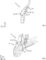
- Fig. 2 shows a perspective view of the frame 6 of the backrest 4.
- the frame 6 has a left and a right frame side part 10, viewed in the longitudinal direction x.
- the two frame side parts 10 are each connected to an upper and lower cross member 8.
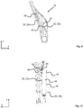
- Fig. 3 shows a side view of an outer side 14 of the left frame side part 10 of the frame 6, viewed in the longitudinal direction x
- Fig. 4 is a perspective view obliquely from above of the left frame side part 10 is shown.
- the embossing 20 comprises a first section 22a and a second section 22b adjacent to the first section 22a.
- the first section 22a and the second section 22b of the embossing 20 are embossed or embossed in opposite directions essentially parallel to the transverse direction y.
- the first section 22a is embossed inward relative to the frame 6.
- the second section 22b is embossed outwards relative to the frame 6.
- a passage opening 24 is arranged 22a of the embossing 20 and the second section 22b of the embossing 20.
- the gas pressure generator 40 can be partially passed through this passage opening 24.
- the embossing 20 has at least one width b in order to receive the gas pressure generator 40 at least partially in the embossing 20.
- the passage opening 24 has at least one opening with a diameter corresponding to the width b.
- the first section 22a and the second section 22b preferably each have at least a depth in the region of half the width b.
- a plurality of through bores 26, in this case three through bores 26, are arranged next to one another parallel to a longitudinal extension of the embossing 20.
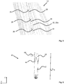
- Fig. 5 an enlarged section of an inner side 12 of the frame side part 10 in the area of the through bores 26 is shown.
- the plurality of through bores 26 is used to position the gas pressure generator 40 relative to the frame side part 10.
- the through bores 26 are each bordered by a preferably annular, flattened area 28. This flattened area 28 enables a planar introduction of force for fastening the gas pressure generator 40.
- Fig. 6 shows the gas pressure generator 40.
- the gas pressure generator 40 has a threaded bolt 48 protruding perpendicularly from a housing 42 of the gas pressure generator 40.
- the gas pressure generator 40 has a gas baffle 44 fixed to the housing 42, by means of which outflowing gas can be directed in a predetermined flow direction.
- the gas pressure generator 40 On a side opposite the gas baffle 44, the gas pressure generator 40 has a multiplicity of gas outlet openings 46 through which the released gas can exit.
- a plug connection for connecting a release control is provided at an end section of the gas pressure generator 40 remote from the threaded bolt 48.
- FIG. 9 shows an inner side 12 of the frame side part 10 with the mounted gas pressure generator 40.
- the gas pressure generator 40 is fastened to the frame side part 10 by means of the threaded bolt 48 guided through one of the through bores 26.
- the threaded bolt 48 of the gas pressure generator 40 is for this purpose, as in Fig. 10 shown, fixed to the frame side part 10 by means of a nut 60.
- the nut 60 is screwed onto the threaded bolt 48 from the side of the frame side part 10 opposite the gas pressure generator 40.
- the nut 60 here lies flat against the flattened area 28 arranged around the through hole 26.
Landscapes
- Engineering & Computer Science (AREA)
- Mechanical Engineering (AREA)
- Aviation & Aerospace Engineering (AREA)
- Transportation (AREA)
- Physics & Mathematics (AREA)
- Fluid Mechanics (AREA)
- Air Bags (AREA)
- Seats For Vehicles (AREA)
Description
- Die Erfindung betrifft einen Fahrzeugsitz, insbesondere Kraftfahrzeugsitz, aufweisend ein Sitzteil und eine Lehne, wobei wenigstens das Sitzteil oder die Lehne einen Rahmen aufweist, wobei der Rahmen wenigstens ein Rahmenseitenteil umfasst.
- Fahrzeugsitze werden aktuell mit integrierten Sicherheitsmerkmalen zum Schutz des Fahrzeuginsassen bereitgestellt. Fahrzeugsitze müssen derart ausgebildet sein, dass der Fahrzeugsitz strukturell einwandfrei ist und die für einen Fahrzeuginsassen notwendige Unterstützung bereitstellt. Um die Sicherheitsmerkmale eines Fahrzeugsitzes zu verbessern, kann ein Airbag in die Fahrzeugsitzkonstruktion eingebaut werden. Wenn ein Airbag in die Fahrzeugsitzkonstruktion integriert ist, muss der Fahrzeugsitz eine angemessene Entfaltung des Airbags ermöglichen.
- Die
DE 10 2017 120 434 A1 bezieht sich im Allgemeinen auf eine Fahrzeugsitzbaugruppe und insbesondere auf eine Befestigungsarchitektur und Energieübertragungskonstruktion für die Steuerung einer Seitenairbagentfaltung an der Rückenlehne der Fahrzeugsitzbaugruppe. - Aus der
FR 2 924 992 A1 - Aus der
EP 0 788 941 A2 ist eine Seitenaufprall-Airbagvorrichtung in einem Sitzlehnenrahmen einer Sitzstruktur bekannt, wobei der Sitzlehnenrahmen einen Seitenrahmen aufweist, der jeweils an einer entsprechenden Seite eines Sitzes in Querrichtung vorgesehen ist. Ein Airbag ist in einem konkaven Abschnitt aufgenommen, welcher in dem einer Fahrzeugtür gegenüberliegenden Seitenrahmen ausgebildet ist, so dass sich der konkave Abschnitt von einem Endabschnitt des Sitzlehnenrahmens in Querrichtung des Sitzes nach innen erstreckt. Der konkave Abschnitt nimmt einen Gasgenerator und einen gefalteten Airbag auf. Ein Sitzpolster ist zum Abdecken des Sitzlehnenrahmens vorgesehen, und ein Bezug ist zum Abdecken des Sitzpolsters vorgesehen. Der Bezug bedeckt den Airbag, der in dem konkaven Teil und dem Sitzpolster aufgenommen ist. - Aus der
GB 2 296 476 A - Aus der
US 2017/057448 A1 ist ein Insassensicherheitssystem bekannt, welches ein an einem Fahrzeugsitzrahmen montierbares Airbagmodul aufweist. Das Airbagmodul umfasst einen Grundkörper und einen von einem Rahmen aufnehmbaren Rückhaltemechanismus. Der Grundkörper ist an dem Rahmen befestigbar. - Der Erfindung liegt die Aufgabe zu Grunde, einen Fahrzeugsitz der eingangs genannten Art zu verbessern, insbesondere einen Fahrzeugsitz bereitzustellen, welcher eine einfachere und platzsparendere Montage eines Gasdruckerzeugers und/oder eines Airbagmoduls ermöglicht.
- Diese Aufgabe wird erfindungsgemäß gelöst, durch einen Fahrzeugsitz, insbesondere Kraftfahrzeugsitz, aufweisend ein Sitzteil und eine Lehne, wobei wenigstens das Sitzteil oder die Lehne einen Rahmen aufweist, wobei der Rahmen wenigstens ein Rahmenseitenteil umfasst, wobei das Rahmenseitenteil eine Prägung zur Befestigung eines Gasdruckerzeugers für einen Airbag aufweist, wobei die Prägung einen ersten Abschnitt und einen dem ersten Abschnitt benachbarten zweiten Abschnitt umfasst, wobei der erste Abschnitt und der zweite Abschnitt der Prägung im Wesentlichen parallel zur Querrichtung entgegengesetzt eingeprägt bzw. ausgeprägt sind, wobei der erste Abschnitt in Richtung eines Rahmeninneren geprägt ist, wobei der zweite Abschnitt in Richtung eines Rahmenäußeren geprägt ist, wobei in einem Übergangsbereich zwischen dem ersten Abschnitt der Prägung und dem zweiten Abschnitt der Prägung eine Durchtrittsöffnung angeordnet ist.
- Dadurch, dass in einem Übergangsbereich zwischen dem ersten Abschnitt der Prägung und dem zweiten Abschnitt der Prägung eine Durchtrittsöffnung angeordnet ist, lässt sich die Anzahl benötigter weiterer Teile zur Montage des Gasdruckerzeugers reduzieren. Ferner lässt sich hierdurch bei der Montage des Gasdruckerzeugers Zeit sparen und zudem sicherstellen, dass der Gasdruckerzeuger richtig eingebaut ist.
- Vorteilhafte Ausgestaltungen, welche einzeln oder in Kombination miteinander eingesetzt werden können, sind nachfolgend beschreiben.
- Der Rahmen kann die tragende Struktur der Lehne oder des Sitzteils sein. Das Rahmenseitenteil kann Bestandteil eines in der Lehne verbauten Rahmens sein. Das Rahmenseitenteil kann Bestandteil eines in dem Sitzteil verbauten Rahmens sein. Der Airbag kann ein in der Lehne angeordneter Seitenairbag sein. Der Airbag kann ein in einer Seitenwange des Sitzteils angeordneter Seitenairbag sein. Der Fahrzeugsitz kann einen Rahmen mit lediglich einem erfindungsgemäß mit einer Prägung versehenen Rahmenseitenteil aufweisen. Der Fahrzeugsitz kann einen Rahmen mit beidseitig jeweils einem erfindungsgemäß mit einer Prägung versehenen Rahmenseitenteil aufweisen.
- Der erste Abschnitt der Prägung ist vorzugsweise in Richtung eines zweiten gegenüberliegenden Sitzrahmenseitenteils des Rahmens eingeprägt. Insbesondere ist der zweite Abschnitt der Prägung von einem zweiten gegenüberliegenden Sitzrahmenseitenteil des Rahmens weg ausgeprägt.
- Im Bereich des ersten Abschnitts kann wenigstens eine Durchgangsbohrung angeordnet sein. Bevorzugt sind im Bereich des ersten Abschnitts eine Mehrzahl an Durchgangsbohrungen, insbesondere wenigstens zwei Durchgangsbohrungen, angeordnet. Die im Bereich des ersten Abschnitts angeordneten Durchgangsbohrungen sind insbesondere parallel zu einer Längserstreckung der Prägung und einander nebeneinander angeordnet. Die wenigstens zwei Durchgangsbohrungen können einer variablen Positionierung des Gasdruckerzeugers und/oder eines Airbagmoduls relativ zum Rahmenseitenteil dienen. Die wenigstens zwei Durchgangsbohrungen können einen Einsatz von unterschiedlich langen Gasdruckerzeugern ermöglichen.
- Der Gasdruckerzeuger kann Mittel zur Befestigung an dem Rahmenseitenteil aufweisen. Der Gasdruckdruckerzeuger kann wenigstens abschnittsweise in das Rahmenseitenteil eingesteckt sein. Der Gasdruckdruckerzeuger kann mit dem Rahmenseitenteil verclipst sein. Der Gasdruckdruckerzeuger kann eine hakenförmige Nase aufweisen, welche in eine Durchgangsbohrung einsteckbar ist. Der Gasdruckerzeuger kann einen insbesondere senkrecht von einem Gehäuse des Gasdruckerzeugers abstehenden Gewindebolzen aufweisen. Der Gasdruckerzeuger kann mittels des Gewindebolzens an dem Rahmenseitenteil befestigbar sein. Der Gewindebolzen des Gasdruckerzeugers kann zur Montage durch wenigstens eine Durchgangsbohrung des Rahmenseitenteils hindurch geführt sein. Der Gewindebolzen des Gasdruckerzeugers kann mittels einer Mutter an dem Rahmenseitenteil fixierbar sein.
- Die Prägung weist bevorzugt wenigstens eine Breite auf, um den Gasdruckerzeuger wenigstens teilweise, insbesondere wenigstens zur Hälfte, in der Prägung aufzunehmen.
- Der Fahrzeugsitz kann im Fond eines Fahrzeuges angeordnet sein.
- Bevor nachfolgend Ausgestaltungen der Erfindung eingehender an Hand von Zeichnungen beschrieben werden, ist zunächst festzuhalten, dass die Erfindung nicht auf die beschriebenen Komponenten oder die beschriebenen Verfahrensschritte beschränkt ist. Weiterhin stellt auch die verwendete Terminologie keine Einschränkung dar, sondern hat lediglich beispielhaften Charakter. Soweit nachfolgend in der Beschreibung und den Ansprüchen der Singular verwendet wird ist dabei jeweils der Plural mitumfasst, soweit der Kontext dies nicht explizit ausschließt.
- Im Folgenden ist die Erfindung anhand eines in den Figuren dargestellten vorteilhaften Ausführungsbeispiels näher erläutert. Die Erfindung ist jedoch nicht auf dieses Ausführungsbeispiel beschränkt. Es zeigen:
- Fig. 1:
- schematisch einen Fahrzeugsitz,
- Fig. 2:
- eine perspektivische Darstellung eines Rahmens einer Lehne,
- Fig. 3:
- eine Seitenansicht auf eine Außenseite eines Rahmenseitenteils des Rahmens von
Fig. 2 , - Fig. 4:
- eine perspektivische Ansicht von schräg oben auf das Rahmenseitenteil von
Fig. 3 , - Fig. 5:
- eine vergrößerte Ansicht auf eine Innenseite des Rahmenseitenteils von
Fig. 3 , im Bereich von Durchgangsbohrungen, - Fig. 6:
- eine Darstellung eines Gasdruckerzeugers,
- Fig. 7:
- eine der
Fig. 2 entsprechende perspektivische Darstellung des Rahmens mit montiertem Gasdruckerzeuger, - Fig. 8:
- eine der
Fig. 2 entsprechende Seitenansicht auf die Außenseite des Rahmenseitenteils mit montiertem Gasdruckerzeuger, - Fig. 9:
- eine Seitenansicht auf eine Innenseite des Rahmenseitenteils von
Fig. 8 , und - Fig. 10:
- eine Schnittdarstellung entlang der Linie X-X aus
Fig. 8 . - Der in
Figur 1 schematisch dargestellte Fahrzeugsitz 1 wird nachfolgend unter Verwendung von drei senkrecht zueinander verlaufenden Raumrichtungen beschrieben. Eine Längsrichtung x verläuft bei einem im Fahrzeug eingebauten Fahrzeugsitz 1 weitgehend horizontal und vorzugsweise parallel zu einer Fahrzeuglängsrichtung, die der gewöhnlichen Fahrtrichtung des Fahrzeuges entspricht. Eine zu der Längsrichtung x senkrecht verlaufende Querrichtung y ist im Fahrzeug ebenfalls horizontal ausgerichtet und verläuft parallel zu einer Fahrzeugquerrichtung. Eine Vertikalrichtung z verläuft senkrecht zu der Längsrichtung x und senkrecht zu der Querrichtung y. Bei einem im Fahrzeug eingebauten Fahrzeugsitz 1 verläuft die Vertikalrichtung z parallel zu der Fahrzeughochachse. - Die verwendeten Positions- und Richtungsangaben, wie beispielsweise vorne, hinten, oben und unten beziehen sich auf eine Blickrichtung eines im Fahrzeugsitz 1 sitzenden Insassen in normaler Sitzposition, wobei der Fahrzeugsitz 1 im Fahrzeug eingebaut, in einer zur Personenbeförderung geeigneten Gebrauchsposition mit aufrecht stehender Lehne 4 und wie üblich in Fahrtrichtung ausgerichtet ist. Der erfindungsgemäße Fahrzeugsitz 1 kann jedoch auch in abweichender Ausrichtung, beispielsweise quer zur Fahrtrichtung verbaut werden.
- Der Fahrzeugsitz 1 für ein Kraftfahrzeug weist ein Sitzteil 2 und eine relativ zum Sitzteil 2 in ihrer Neigung einstellbare Lehne 4 auf. Wenigstens das Sitzteil 2 oder die Lehne 4 weist als tragende Struktur einen Rahmen 6 auf. Der Rahmen 6 kann aus Stahlblechteilen gefertigt sein. Vorliegend weist die Lehne 4 einen Rahmen 6 auf. Der Rahmen 6 umfasst wenigstens ein Rahmenseitenteil 10, vorliegend zwei in Querrichtung y gegenüberliegende Rahmenseitenteile 10. Die beiden Rahmenseitenteile 10 sind bevorzugt symmetrisch, insbesondere spiegelsymmetrisch, zu einer senkrecht zur Querrichtung y orientierte Mittenebene des Fahrzeugsitzes ausgestaltet. Das Rahmenseitenteil 10 weist eine Prägung 20 zur Befestigung eines in
Fig. 6 dargestellten Gasdruckerzeugers 40. Der Gasdruckerzeuger 40 ist üblicherweise Bestandteil einer Baugruppe, eines sogenannten Airbagmoduls, und ist ferner vor der Montage an dem Fahrzeugsitz mit einem Airbag verbunden. Wenn nachfolgend eine Montage des Gasdruckerzeugers 40 beschrieben wird, bezieht sich dies ebenso auf eine Montage einer den Gasdruckerzeuger 40 aufweisenden Baugruppe bzw. eines Airbagmoduls. -
Fig. 2 zeigt eine perspektivische Darstellung des Rahmens 6 der Lehne 4. Der Rahmen 6 weist jeweils in Längsrichtung x betrachtet ein linkes und rechtes Rahmenseitenteil 10 auf. Die beiden Rahmenseitenteile 10 sind mit je einer oberen und unteren Quertraverse 8 verbunden.Fig. 3 zeigt eine Seitenansicht einer Außenseite 14 des in Längsrichtung x betrachtet linken Rahmenseitenteils 10 des Rahmens 6. InFig. 4 ist eine perspektivische Ansicht von schräg oben auf das linke Rahmenseitenteil 10 gezeigt. - Die Prägung 20 umfasst einen ersten Abschnitt 22a und einen dem ersten Abschnitt 22a benachbarten zweiten Abschnitt 22b. Der erste Abschnitt 22a und der zweite Abschnitt 22b der Prägung 20 sind im Wesentlichen parallel zur Querrichtung y entgegengesetzt eingeprägt bzw. ausgeprägt. Der erste Abschnitt 22a ist relativ zum Rahmen 6 nach innen geprägt. Der zweite Abschnitt 22b ist relativ zum Rahmen 6 nach außen geprägt. In einem Übergangsbereich zwischen dem ersten Abschnitt 22a der Prägung 20 und dem zweiten Abschnitt 22b der Prägung 20 ist eine Durchtrittsöffnung 24 angeordnet. Durch diese Durchtrittsöffnung 24 ist der Gasdruckerzeuger 40 teilweise hindurchführbar.
- Die Prägung 20 weist wenigstens eine Breite b auf, um den Gasdruckerzeuger 40 wenigstens teilweise in der Prägung 20 aufzunehmen. Im Falle von im Querschnitt runden Gasdruckerzeugern 40, weist die Durchtrittsöffnung 24 wenigstens eine Öffnung mit einem Durchmesser entsprechend der Breite b auf. Bevorzugt weist der erste Abschnitt 22a und der zweite Abschnitt 22b jeweils wenigstens eine Tiefe im Bereich der halben Breite b auf.
- Ferner ist im Bereich des ersten Abschnitts 22a eine Mehrzahl an Durchgangsbohrungen 26, vorliegend drei Durchgangsbohrungen 26, parallel zu einer Längserstreckung der Prägung 20 nebeneinander angeordnet. In
Fig. 5 ist eine ausschnittsweise vergrößerte Darstellung einer Innenseite 12 des Rahmenseitenteils 10 im Bereich der Durchgangsbohrungen 26 gezeigt. Die Mehrzahl an Durchgangsbohrungen 26 dient einer Positionierung des Gasdruckerzeugers 40 relativ zum Rahmenseitenteil 10. Zusätzlich wird es ermöglicht, verschiedene Gasdruckerzeuger 40 mit unterschiedlicher Länge a einzusetzen. Die Durchgangsbohrungen 26 sind jeweils von einem, bevorzugt ringförmigen, abgeflachten Bereich 28 umrandet. Dieser abgeflachte Bereich 28 ermöglicht eine flächige Krafteinleitung für eine Befestigung des Gasdruckerzeugers 40. -
Fig. 6 zeigt den Gasdruckerzeuger 40. Der Gasdruckerzeuger 40 weist einen senkrecht von einem Gehäuse 42 des Gasdruckerzeugers 40 abstehenden Gewindebolzen 48 auf. Der Gasdruckerzeuger 40 weist ein an dem Gehäuse 42 fixiertes Gasleitblech 44 auf, mittels welchem ausströmendes Gas in eine vorgegebene Strömungsrichtung geleitet werden kann. Der Gasdruckerzeuger 40 weist auf einer dem Gasleitblech 44 gegenüberliegenden Seite eine Vielzahl an Gasaustrittsöffnungen 46 auf, durch welche hindurch das freigesetzte Gas austreten kann. An einem dem Gewindebolzen 48 entfernten Endabschnitt des Gasdruckerzeugers 40 ist eine Steckverbindung zum Anschließen einer Auslösesteuerung vorgesehen. - Die
Figuren 7 und 8 entsprechend im Wesentlichen den Darstellungen derFiguren 2 und3 mit dem Unterschied, dass der Gasdruckerzeuger 40 montiert ist.Fig. 9 zeigt eine Innenseite 12 des Rahmenseitenteils 10 mit dem montierten Gasdruckerzeuger 40. Der Gasdruckerzeuger 40 ist in montiertem Zustand mittels des durch eine der Durchgangsbohrungen 26 hindurch geführten Gewindebolzens 48 an dem Rahmenseitenteil 10 befestigt. Der Gewindebolzen 48 des Gasdruckerzeugers 40 ist hierzu, wie inFig. 10 gezeigt, mittels einer Mutter 60 an dem Rahmenseitenteil 10 fixiert. Die Mutter 60 ist von der dem Gasdruckerzeuger 40 gegenüberliegenden Seite des Rahmenseitenteils 10 auf den Gewindebolzen 48 aufgeschraubt. Die Mutter 60 liegt hierbei flächig an dem um die Durchgangsbohrung 26 angeordneten abgeflachten Bereich 28 an. - Obwohl die Erfindung in den Zeichnungen und der vorausgegangenen Darstellung im Detail beschrieben wurde, sind die Darstellungen illustrativ und beispielhaft und nicht einschränkend zu verstehen. Insbesondere ist die Wahl der zeichnerisch dargestellten Proportionen der einzelnen Elemente nicht als erforderlich oder beschränkend auszulegen. Weiterhin ist die Erfindung insbesondere nicht auf die erläuterten Ausführungsbeispiele beschränkt. Weitere Varianten der Erfindung und ihre Ausführung ergeben sich für den Fachmann aus der vorangegangenen Offenbarung, den Figuren und den Ansprüchen.
- In den Ansprüchen verwendete Begriffe wie "umfassen", "aufweisen", "beinhalten", "enthalten" und dergleichen schließen weitere Elemente oder Schritte nicht aus. Die Verwendung des unbestimmten Artikels schließt eine Mehrzahl nicht aus. Eine einzelne Einrichtung kann die Funktionen mehrerer in den Ansprüchen genannten Einheiten bzw. Einrichtungen ausführen.
-
- 1
- Fahrzeugsitz
- 2
- Sitzteil
- 4
- Lehne
- 6
- Rahmen
- 8
- Quertraverse
- 10
- Rahmenseitenteil
- 12
- Innenseite
- 14
- Außenseite
- 20
- Prägung
- 22a
- erster Abschnitt
- 22b
- zweiter Abschnitt
- 24
- Durchtrittsöffnung
- 26
- Durchgangsbohrung
- 28
- abgeflachter Bereich
- 40
- Gasdruckerzeuger
- 42
- Gehäuse
- 44
- Gasleitblech
- 46
- Gasaustrittsöffnung
- 48
- Gewindebolzen
- 60
- Mutter
- a
- Länge
- b
- Breite
- x
- Längsrichtung
- y
- Querrichtung
- z
- Vertikalrichtung
Claims (6)
- Fahrzeugsitz (1), insbesondere Kraftfahrzeugsitz, aufweisend ein Sitzteil (2) und eine Lehne (4), wobei wenigstens das Sitzteil (2) oder die Lehne (4) einen Rahmen (6) aufweist, wobei der Rahmen (6) wenigstens ein Rahmenseitenteil (10) umfasst, wobei das Rahmenseitenteil (10) eine Prägung (20) zur Befestigung eines Gasdruckerzeugers (40) für einen Airbag aufweist, wobei die Prägung (20) einen ersten Abschnitt (22a) und einen dem ersten Abschnitt (22a) benachbarten zweiten Abschnitt (22b) umfasst, wobei der erste Abschnitt (22a) und der zweite Abschnitt (22b) der Prägung (20) im Wesentlichen parallel zur Querrichtung (y) entgegengesetzt eingeprägt bzw. ausgeprägt sind, wobei der erste Abschnitt (22a) in Richtung eines Rahmeninneren geprägt ist, wobei der zweite Abschnitt (22b) in Richtung eines Rahmenäußeren geprägt ist, dadurch gekennzeichnet, dass
in einem Übergangsbereich zwischen dem ersten Abschnitt (22a) der Prägung (20) und dem zweiten Abschnitt (22b) der Prägung (20) eine Durchtrittsöffnung (24) angeordnet ist. - Fahrzeugsitz (1) nach Anspruch 1, wobei im Bereich des ersten Abschnitts (22a) wenigstens eine Durchgangsbohrung (26) angeordnet ist.
- Fahrzeugsitz (1) nach einem der Ansprüche 1 oder 2, wobei im Bereich des ersten Abschnitts (22a) eine Mehrzahl an Durchgangsbohrungen (26) parallel zu einer Längserstreckung der Prägung (20) nebeneinander angeordnet ist.
- Fahrzeugsitz (1) nach Anspruch 3, wobei die Mehrzahl an Durchgangsbohrungen (26) einer Positionierung des Gasdruckerzeugers (40) relativ zum Rahmenseitenteil (10) dient.
- Fahrzeugsitz (1) nach einem der Ansprüche 3 oder 4, wobei die Mehrzahl an Durchgangsbohrungen (26) einen Einsatz von unterschiedlich langen Gasdruckerzeugern (40) ermöglicht.
- Fahrzeugsitz (1) nach einem der Ansprüche 1 bis 5, wobei die Prägung (20) wenigstens eine Breite (b) aufweist, um den Gasdruckerzeuger (40) wenigstens teilweise, bevorzugt zur Hälfte, in die Prägung (20) einzufügen.
Priority Applications (4)
| Application Number | Priority Date | Filing Date | Title |
|---|---|---|---|
| EP18165911.1A EP3549821B1 (de) | 2018-04-05 | 2018-04-05 | Fahrzeugsitz |
| PCT/EP2019/058304 WO2019193008A1 (de) | 2018-04-05 | 2019-04-02 | Fahrzeugsitz |
| CN201980024097.0A CN111954610B (zh) | 2018-04-05 | 2019-04-02 | 车辆座椅 |
| US16/978,824 US11458924B2 (en) | 2018-04-05 | 2019-04-02 | Vehicle seat |
Applications Claiming Priority (1)
| Application Number | Priority Date | Filing Date | Title |
|---|---|---|---|
| EP18165911.1A EP3549821B1 (de) | 2018-04-05 | 2018-04-05 | Fahrzeugsitz |
Publications (2)
| Publication Number | Publication Date |
|---|---|
| EP3549821A1 EP3549821A1 (de) | 2019-10-09 |
| EP3549821B1 true EP3549821B1 (de) | 2021-08-11 |
Family
ID=61911429
Family Applications (1)
| Application Number | Title | Priority Date | Filing Date |
|---|---|---|---|
| EP18165911.1A Active EP3549821B1 (de) | 2018-04-05 | 2018-04-05 | Fahrzeugsitz |
Country Status (4)
| Country | Link |
|---|---|
| US (1) | US11458924B2 (de) |
| EP (1) | EP3549821B1 (de) |
| CN (1) | CN111954610B (de) |
| WO (1) | WO2019193008A1 (de) |
Families Citing this family (2)
| Publication number | Priority date | Publication date | Assignee | Title |
|---|---|---|---|---|
| US11639125B2 (en) * | 2021-07-19 | 2023-05-02 | Lear Corporation | Vehicle seat assembly and method of assembling |
| US12344180B1 (en) * | 2024-08-07 | 2025-07-01 | Lear Corporation | Seat assembly |
Family Cites Families (8)
| Publication number | Priority date | Publication date | Assignee | Title |
|---|---|---|---|---|
| US5651582A (en) * | 1994-12-20 | 1997-07-29 | Ikeda Bussan Co., Ltd. | Vehicular seat with side air-bag |
| JP3000161B2 (ja) * | 1994-12-20 | 2000-01-17 | 池田物産株式会社 | 車両用シート |
| JP3141747B2 (ja) * | 1995-09-18 | 2001-03-05 | トヨタ自動車株式会社 | 側突用エアバッグ装置を備えたシート構造 |
| FR2924992B1 (fr) * | 2007-12-18 | 2010-10-22 | Faurecia Sieges Automobile | Structure de siege et ensemble comprenant une portion de reception pour generateur de gaz pour coussin gonflable |
| FR3005009B1 (fr) * | 2013-04-24 | 2016-03-18 | Peugeot Citroen Automobiles Sa | Flasque d'armature de dossier de siege de vehicule automobile muni de moyens de pre-maintien d'un airbag lateral. |
| US20170057448A1 (en) * | 2015-09-02 | 2017-03-02 | Ford Global Technologies, Llc | Vehicle occupant safety system |
| DE102017120434A1 (de) | 2016-09-07 | 2018-03-08 | Ford Global Technologies, Llc | Rückenlehne mit seitenairbagenergiemanagementsystem |
| US10239430B2 (en) * | 2016-09-28 | 2019-03-26 | Nissan North America, Inc. | Vehicle seat and airbag structure |
-
2018
- 2018-04-05 EP EP18165911.1A patent/EP3549821B1/de active Active
-
2019
- 2019-04-02 WO PCT/EP2019/058304 patent/WO2019193008A1/de not_active Ceased
- 2019-04-02 US US16/978,824 patent/US11458924B2/en active Active
- 2019-04-02 CN CN201980024097.0A patent/CN111954610B/zh active Active
Also Published As
| Publication number | Publication date |
|---|---|
| CN111954610A (zh) | 2020-11-17 |
| US20210046892A1 (en) | 2021-02-18 |
| EP3549821A1 (de) | 2019-10-09 |
| CN111954610B (zh) | 2023-02-28 |
| WO2019193008A1 (de) | 2019-10-10 |
| US11458924B2 (en) | 2022-10-04 |
Similar Documents
| Publication | Publication Date | Title |
|---|---|---|
| EP3484743B1 (de) | Längseinsteller sowie fahrzeugsitz | |
| WO2008077485A1 (de) | Vorhang-gassack | |
| EP4301631B1 (de) | Lasttragender gurtaufroller und sitzstruktur | |
| DE102007046958A1 (de) | Energieabsorptions-Sitzverankerungs-Rückhaltesystem für Kinder-Sicherheitssitze | |
| EP3663138B1 (de) | Befestigungselement zur fahrzeugseitigen montage eines gassackmoduls | |
| WO2022073997A1 (de) | Fahrzeuginsassenschutzsystem und verfahren zur aktivierung eines fahrzeuginsassenschutzsystems | |
| EP3549821B1 (de) | Fahrzeugsitz | |
| EP1855901B1 (de) | Vorrichtung für ein kraftfahrzeug zum insassenschutz bei einem kollisionsbedingten, auf eine kraftfahrzeugtür gerichteten energieeintrag | |
| EP3321126B1 (de) | Gurtgestell für einen fahrzeugsitz | |
| EP4480761B1 (de) | Gurtaufroller | |
| EP4211004A1 (de) | Gurtaufroller | |
| EP3366511B1 (de) | Gurtgestell für einen fahrzeugsitz oder eine fahrzeugsitzbank | |
| WO2020088920A1 (de) | Gasbefüllbares stützmittel für ein kraftfahrzeug sowie hiermit ausgestattetes kraftfahrzeug | |
| DE102016117888A1 (de) | Vorrichtung zur Anordnung eines Personenrückhaltesystems | |
| EP2060422B1 (de) | Rolloeinrichtung für ein Kraftfahrzeug | |
| DE102005042026A1 (de) | Vorhanggassack-Einheit | |
| EP3548354B1 (de) | Schienenfahrzeug mit wandartiger trennvorrichtung | |
| EP4003790B1 (de) | Verkleidungsanordnung zur innenraumausstattung eines kraftfahrzeugs, eine kraftfahrzeugtür sowie kraftfahrzeug | |
| EP2566726A1 (de) | Rahmenvorrichtung für ein überrollschutzsystem und überrollschutzsystem mit einer rahmenvorrichtung | |
| EP2724899B1 (de) | Sicherheitsgurtvorrichtung für eine Rücksitzanordnung eines Fahrzeuges | |
| EP1820729B1 (de) | Flugzeugsitzbefestigungsvorrichtung | |
| EP3238988B1 (de) | Vorrichtung zur anordnung eines personenrückhaltesystems | |
| EP3870477B1 (de) | Rahmen für einen fahrzeugsitz, fahrzeugsitz für ein kraftfahrzeug | |
| DE102005011162A1 (de) | Vorrichtung für ein Kraftfahrzeug zum Insassenschutz bei einem kollisionsbedingten, auf eine Kraftfahrzeugtür gerichteten Engergieeintrag | |
| EP3341240B1 (de) | Vorrichtung zur anbringung eines fahrzeugsitzes |
Legal Events
| Date | Code | Title | Description |
|---|---|---|---|
| PUAI | Public reference made under article 153(3) epc to a published international application that has entered the european phase |
Free format text: ORIGINAL CODE: 0009012 |
|
| STAA | Information on the status of an ep patent application or granted ep patent |
Free format text: STATUS: THE APPLICATION HAS BEEN PUBLISHED |
|
| AK | Designated contracting states |
Kind code of ref document: A1 Designated state(s): AL AT BE BG CH CY CZ DE DK EE ES FI FR GB GR HR HU IE IS IT LI LT LU LV MC MK MT NL NO PL PT RO RS SE SI SK SM TR |
|
| AX | Request for extension of the european patent |
Extension state: BA ME |
|
| STAA | Information on the status of an ep patent application or granted ep patent |
Free format text: STATUS: REQUEST FOR EXAMINATION WAS MADE |
|
| 17P | Request for examination filed |
Effective date: 20200409 |
|
| RBV | Designated contracting states (corrected) |
Designated state(s): AL AT BE BG CH CY CZ DE DK EE ES FI FR GB GR HR HU IE IS IT LI LT LU LV MC MK MT NL NO PL PT RO RS SE SI SK SM TR |
|
| GRAP | Despatch of communication of intention to grant a patent |
Free format text: ORIGINAL CODE: EPIDOSNIGR1 |
|
| STAA | Information on the status of an ep patent application or granted ep patent |
Free format text: STATUS: GRANT OF PATENT IS INTENDED |
|
| INTG | Intention to grant announced |
Effective date: 20210331 |
|
| GRAS | Grant fee paid |
Free format text: ORIGINAL CODE: EPIDOSNIGR3 |
|
| GRAA | (expected) grant |
Free format text: ORIGINAL CODE: 0009210 |
|
| STAA | Information on the status of an ep patent application or granted ep patent |
Free format text: STATUS: THE PATENT HAS BEEN GRANTED |
|
| AK | Designated contracting states |
Kind code of ref document: B1 Designated state(s): AL AT BE BG CH CY CZ DE DK EE ES FI FR GB GR HR HU IE IS IT LI LT LU LV MC MK MT NL NO PL PT RO RS SE SI SK SM TR |
|
| REG | Reference to a national code |
Ref country code: CH Ref legal event code: EP |
|
| REG | Reference to a national code |
Ref country code: DE Ref legal event code: R096 Ref document number: 502018006496 Country of ref document: DE |
|
| REG | Reference to a national code |
Ref country code: IE Ref legal event code: FG4D Free format text: LANGUAGE OF EP DOCUMENT: GERMAN Ref country code: AT Ref legal event code: REF Ref document number: 1419065 Country of ref document: AT Kind code of ref document: T Effective date: 20210915 |
|
| REG | Reference to a national code |
Ref country code: LT Ref legal event code: MG9D |
|
| REG | Reference to a national code |
Ref country code: NL Ref legal event code: MP Effective date: 20210811 |
|
| REG | Reference to a national code |
Ref country code: DE Ref legal event code: R082 Ref document number: 502018006496 Country of ref document: DE Representative=s name: LIEDHEGENER, RALF, DIPL.-ING., DE Ref country code: DE Ref legal event code: R082 Ref document number: 502018006496 Country of ref document: DE Representative=s name: LIEDTKE & PARTNER PATENTANWAELTE, DE |
|
| PG25 | Lapsed in a contracting state [announced via postgrant information from national office to epo] |
Ref country code: HR Free format text: LAPSE BECAUSE OF FAILURE TO SUBMIT A TRANSLATION OF THE DESCRIPTION OR TO PAY THE FEE WITHIN THE PRESCRIBED TIME-LIMIT Effective date: 20210811 Ref country code: ES Free format text: LAPSE BECAUSE OF FAILURE TO SUBMIT A TRANSLATION OF THE DESCRIPTION OR TO PAY THE FEE WITHIN THE PRESCRIBED TIME-LIMIT Effective date: 20210811 Ref country code: FI Free format text: LAPSE BECAUSE OF FAILURE TO SUBMIT A TRANSLATION OF THE DESCRIPTION OR TO PAY THE FEE WITHIN THE PRESCRIBED TIME-LIMIT Effective date: 20210811 Ref country code: RS Free format text: LAPSE BECAUSE OF FAILURE TO SUBMIT A TRANSLATION OF THE DESCRIPTION OR TO PAY THE FEE WITHIN THE PRESCRIBED TIME-LIMIT Effective date: 20210811 Ref country code: SE Free format text: LAPSE BECAUSE OF FAILURE TO SUBMIT A TRANSLATION OF THE DESCRIPTION OR TO PAY THE FEE WITHIN THE PRESCRIBED TIME-LIMIT Effective date: 20210811 Ref country code: PT Free format text: LAPSE BECAUSE OF FAILURE TO SUBMIT A TRANSLATION OF THE DESCRIPTION OR TO PAY THE FEE WITHIN THE PRESCRIBED TIME-LIMIT Effective date: 20211213 Ref country code: NO Free format text: LAPSE BECAUSE OF FAILURE TO SUBMIT A TRANSLATION OF THE DESCRIPTION OR TO PAY THE FEE WITHIN THE PRESCRIBED TIME-LIMIT Effective date: 20211111 Ref country code: BG Free format text: LAPSE BECAUSE OF FAILURE TO SUBMIT A TRANSLATION OF THE DESCRIPTION OR TO PAY THE FEE WITHIN THE PRESCRIBED TIME-LIMIT Effective date: 20211111 Ref country code: LT Free format text: LAPSE BECAUSE OF FAILURE TO SUBMIT A TRANSLATION OF THE DESCRIPTION OR TO PAY THE FEE WITHIN THE PRESCRIBED TIME-LIMIT Effective date: 20210811 |
|
| PG25 | Lapsed in a contracting state [announced via postgrant information from national office to epo] |
Ref country code: PL Free format text: LAPSE BECAUSE OF FAILURE TO SUBMIT A TRANSLATION OF THE DESCRIPTION OR TO PAY THE FEE WITHIN THE PRESCRIBED TIME-LIMIT Effective date: 20210811 Ref country code: LV Free format text: LAPSE BECAUSE OF FAILURE TO SUBMIT A TRANSLATION OF THE DESCRIPTION OR TO PAY THE FEE WITHIN THE PRESCRIBED TIME-LIMIT Effective date: 20210811 Ref country code: GR Free format text: LAPSE BECAUSE OF FAILURE TO SUBMIT A TRANSLATION OF THE DESCRIPTION OR TO PAY THE FEE WITHIN THE PRESCRIBED TIME-LIMIT Effective date: 20211112 |
|
| PG25 | Lapsed in a contracting state [announced via postgrant information from national office to epo] |
Ref country code: NL Free format text: LAPSE BECAUSE OF FAILURE TO SUBMIT A TRANSLATION OF THE DESCRIPTION OR TO PAY THE FEE WITHIN THE PRESCRIBED TIME-LIMIT Effective date: 20210811 |
|
| PG25 | Lapsed in a contracting state [announced via postgrant information from national office to epo] |
Ref country code: DK Free format text: LAPSE BECAUSE OF FAILURE TO SUBMIT A TRANSLATION OF THE DESCRIPTION OR TO PAY THE FEE WITHIN THE PRESCRIBED TIME-LIMIT Effective date: 20210811 |
|
| REG | Reference to a national code |
Ref country code: DE Ref legal event code: R097 Ref document number: 502018006496 Country of ref document: DE |
|
| PG25 | Lapsed in a contracting state [announced via postgrant information from national office to epo] |
Ref country code: SM Free format text: LAPSE BECAUSE OF FAILURE TO SUBMIT A TRANSLATION OF THE DESCRIPTION OR TO PAY THE FEE WITHIN THE PRESCRIBED TIME-LIMIT Effective date: 20210811 Ref country code: SK Free format text: LAPSE BECAUSE OF FAILURE TO SUBMIT A TRANSLATION OF THE DESCRIPTION OR TO PAY THE FEE WITHIN THE PRESCRIBED TIME-LIMIT Effective date: 20210811 Ref country code: RO Free format text: LAPSE BECAUSE OF FAILURE TO SUBMIT A TRANSLATION OF THE DESCRIPTION OR TO PAY THE FEE WITHIN THE PRESCRIBED TIME-LIMIT Effective date: 20210811 Ref country code: EE Free format text: LAPSE BECAUSE OF FAILURE TO SUBMIT A TRANSLATION OF THE DESCRIPTION OR TO PAY THE FEE WITHIN THE PRESCRIBED TIME-LIMIT Effective date: 20210811 Ref country code: CZ Free format text: LAPSE BECAUSE OF FAILURE TO SUBMIT A TRANSLATION OF THE DESCRIPTION OR TO PAY THE FEE WITHIN THE PRESCRIBED TIME-LIMIT Effective date: 20210811 Ref country code: AL Free format text: LAPSE BECAUSE OF FAILURE TO SUBMIT A TRANSLATION OF THE DESCRIPTION OR TO PAY THE FEE WITHIN THE PRESCRIBED TIME-LIMIT Effective date: 20210811 |
|
| PLBE | No opposition filed within time limit |
Free format text: ORIGINAL CODE: 0009261 |
|
| STAA | Information on the status of an ep patent application or granted ep patent |
Free format text: STATUS: NO OPPOSITION FILED WITHIN TIME LIMIT |
|
| RAP2 | Party data changed (patent owner data changed or rights of a patent transferred) |
Owner name: ADIENT US LLC |
|
| 26N | No opposition filed |
Effective date: 20220512 |
|
| REG | Reference to a national code |
Ref country code: DE Ref legal event code: R081 Ref document number: 502018006496 Country of ref document: DE Owner name: ADIENT US LLC, PLYMOUTH, US Free format text: FORMER OWNER: ADIENT ENGINEERING AND IP GMBH, 51399 BURSCHEID, DE |
|
| PG25 | Lapsed in a contracting state [announced via postgrant information from national office to epo] |
Ref country code: IT Free format text: LAPSE BECAUSE OF FAILURE TO SUBMIT A TRANSLATION OF THE DESCRIPTION OR TO PAY THE FEE WITHIN THE PRESCRIBED TIME-LIMIT Effective date: 20210811 |
|
| PG25 | Lapsed in a contracting state [announced via postgrant information from national office to epo] |
Ref country code: SI Free format text: LAPSE BECAUSE OF FAILURE TO SUBMIT A TRANSLATION OF THE DESCRIPTION OR TO PAY THE FEE WITHIN THE PRESCRIBED TIME-LIMIT Effective date: 20210811 |
|
| REG | Reference to a national code |
Ref country code: CH Ref legal event code: PL |
|
| GBPC | Gb: european patent ceased through non-payment of renewal fee |
Effective date: 20220405 |
|
| REG | Reference to a national code |
Ref country code: BE Ref legal event code: MM Effective date: 20220430 |
|
| PG25 | Lapsed in a contracting state [announced via postgrant information from national office to epo] |
Ref country code: MC Free format text: LAPSE BECAUSE OF FAILURE TO SUBMIT A TRANSLATION OF THE DESCRIPTION OR TO PAY THE FEE WITHIN THE PRESCRIBED TIME-LIMIT Effective date: 20210811 Ref country code: LU Free format text: LAPSE BECAUSE OF NON-PAYMENT OF DUE FEES Effective date: 20220405 Ref country code: LI Free format text: LAPSE BECAUSE OF NON-PAYMENT OF DUE FEES Effective date: 20220430 Ref country code: GB Free format text: LAPSE BECAUSE OF NON-PAYMENT OF DUE FEES Effective date: 20220405 Ref country code: CH Free format text: LAPSE BECAUSE OF NON-PAYMENT OF DUE FEES Effective date: 20220430 |
|
| PG25 | Lapsed in a contracting state [announced via postgrant information from national office to epo] |
Ref country code: BE Free format text: LAPSE BECAUSE OF NON-PAYMENT OF DUE FEES Effective date: 20220430 |
|
| PG25 | Lapsed in a contracting state [announced via postgrant information from national office to epo] |
Ref country code: IE Free format text: LAPSE BECAUSE OF NON-PAYMENT OF DUE FEES Effective date: 20220405 |
|
| PG25 | Lapsed in a contracting state [announced via postgrant information from national office to epo] |
Ref country code: HU Free format text: LAPSE BECAUSE OF FAILURE TO SUBMIT A TRANSLATION OF THE DESCRIPTION OR TO PAY THE FEE WITHIN THE PRESCRIBED TIME-LIMIT; INVALID AB INITIO Effective date: 20180405 |
|
| PG25 | Lapsed in a contracting state [announced via postgrant information from national office to epo] |
Ref country code: MK Free format text: LAPSE BECAUSE OF FAILURE TO SUBMIT A TRANSLATION OF THE DESCRIPTION OR TO PAY THE FEE WITHIN THE PRESCRIBED TIME-LIMIT Effective date: 20210811 Ref country code: CY Free format text: LAPSE BECAUSE OF FAILURE TO SUBMIT A TRANSLATION OF THE DESCRIPTION OR TO PAY THE FEE WITHIN THE PRESCRIBED TIME-LIMIT Effective date: 20210811 |
|
| REG | Reference to a national code |
Ref country code: AT Ref legal event code: MM01 Ref document number: 1419065 Country of ref document: AT Kind code of ref document: T Effective date: 20230405 |
|
| PG25 | Lapsed in a contracting state [announced via postgrant information from national office to epo] |
Ref country code: AT Free format text: LAPSE BECAUSE OF NON-PAYMENT OF DUE FEES Effective date: 20230405 |
|
| PG25 | Lapsed in a contracting state [announced via postgrant information from national office to epo] |
Ref country code: AT Free format text: LAPSE BECAUSE OF NON-PAYMENT OF DUE FEES Effective date: 20230405 |
|
| PG25 | Lapsed in a contracting state [announced via postgrant information from national office to epo] |
Ref country code: MT Free format text: LAPSE BECAUSE OF FAILURE TO SUBMIT A TRANSLATION OF THE DESCRIPTION OR TO PAY THE FEE WITHIN THE PRESCRIBED TIME-LIMIT Effective date: 20210811 |
|
| REG | Reference to a national code |
Ref country code: DE Ref legal event code: R082 Ref document number: 502018006496 Country of ref document: DE Representative=s name: LIEDTKE & PARTNER PATENTANWAELTE, DE |
|
| PGFP | Annual fee paid to national office [announced via postgrant information from national office to epo] |
Ref country code: DE Payment date: 20250429 Year of fee payment: 8 |
|
| PGFP | Annual fee paid to national office [announced via postgrant information from national office to epo] |
Ref country code: FR Payment date: 20250425 Year of fee payment: 8 |
|
| PG25 | Lapsed in a contracting state [announced via postgrant information from national office to epo] |
Ref country code: TR Free format text: LAPSE BECAUSE OF FAILURE TO SUBMIT A TRANSLATION OF THE DESCRIPTION OR TO PAY THE FEE WITHIN THE PRESCRIBED TIME-LIMIT Effective date: 20210811 |
|
| PGFP | Annual fee paid to national office [announced via postgrant information from national office to epo] |
Ref country code: AT Payment date: 20260410 Year of fee payment: 5 |