EP3549716B1 - Machine tool - Google Patents
Machine tool Download PDFInfo
- Publication number
- EP3549716B1 EP3549716B1 EP19166844.1A EP19166844A EP3549716B1 EP 3549716 B1 EP3549716 B1 EP 3549716B1 EP 19166844 A EP19166844 A EP 19166844A EP 3549716 B1 EP3549716 B1 EP 3549716B1
- Authority
- EP
- European Patent Office
- Prior art keywords
- tool
- shank
- insertion portion
- spindle
- gap
- Prior art date
- Legal status (The legal status is an assumption and is not a legal conclusion. Google has not performed a legal analysis and makes no representation as to the accuracy of the status listed.)
- Active
Links
- 238000003780 insertion Methods 0.000 claims description 82
- 230000037431 insertion Effects 0.000 claims description 82
- 230000008859 change Effects 0.000 claims description 45
- 230000007246 mechanism Effects 0.000 description 12
- 230000033001 locomotion Effects 0.000 description 11
- 238000003754 machining Methods 0.000 description 10
- 230000000452 restraining effect Effects 0.000 description 10
- 238000010926 purge Methods 0.000 description 8
- 230000004048 modification Effects 0.000 description 7
- 238000012986 modification Methods 0.000 description 7
- 230000000694 effects Effects 0.000 description 3
- 238000004140 cleaning Methods 0.000 description 2
- 238000000034 method Methods 0.000 description 2
- 238000003801 milling Methods 0.000 description 2
- 230000005540 biological transmission Effects 0.000 description 1
- 238000006243 chemical reaction Methods 0.000 description 1
- 238000009434 installation Methods 0.000 description 1
- 230000003252 repetitive effect Effects 0.000 description 1
Images


Classifications
-
- B—PERFORMING OPERATIONS; TRANSPORTING
- B23—MACHINE TOOLS; METAL-WORKING NOT OTHERWISE PROVIDED FOR
- B23B—TURNING; BORING
- B23B31/00—Chucks; Expansion mandrels; Adaptations thereof for remote control
- B23B31/006—Conical shanks of tools
-
- B—PERFORMING OPERATIONS; TRANSPORTING
- B23—MACHINE TOOLS; METAL-WORKING NOT OTHERWISE PROVIDED FOR
- B23Q—DETAILS, COMPONENTS, OR ACCESSORIES FOR MACHINE TOOLS, e.g. ARRANGEMENTS FOR COPYING OR CONTROLLING; MACHINE TOOLS IN GENERAL CHARACTERISED BY THE CONSTRUCTION OF PARTICULAR DETAILS OR COMPONENTS; COMBINATIONS OR ASSOCIATIONS OF METAL-WORKING MACHINES, NOT DIRECTED TO A PARTICULAR RESULT
- B23Q11/00—Accessories fitted to machine tools for keeping tools or parts of the machine in good working condition or for cooling work; Safety devices specially combined with or arranged in, or specially adapted for use in connection with, machine tools
- B23Q11/0042—Devices for removing chips
- B23Q11/005—Devices for removing chips by blowing
-
- B—PERFORMING OPERATIONS; TRANSPORTING
- B23—MACHINE TOOLS; METAL-WORKING NOT OTHERWISE PROVIDED FOR
- B23Q—DETAILS, COMPONENTS, OR ACCESSORIES FOR MACHINE TOOLS, e.g. ARRANGEMENTS FOR COPYING OR CONTROLLING; MACHINE TOOLS IN GENERAL CHARACTERISED BY THE CONSTRUCTION OF PARTICULAR DETAILS OR COMPONENTS; COMBINATIONS OR ASSOCIATIONS OF METAL-WORKING MACHINES, NOT DIRECTED TO A PARTICULAR RESULT
- B23Q11/00—Accessories fitted to machine tools for keeping tools or parts of the machine in good working condition or for cooling work; Safety devices specially combined with or arranged in, or specially adapted for use in connection with, machine tools
- B23Q11/02—Devices for removing scrap from the cutting teeth of circular or non-circular cutters
-
- B—PERFORMING OPERATIONS; TRANSPORTING
- B23—MACHINE TOOLS; METAL-WORKING NOT OTHERWISE PROVIDED FOR
- B23Q—DETAILS, COMPONENTS, OR ACCESSORIES FOR MACHINE TOOLS, e.g. ARRANGEMENTS FOR COPYING OR CONTROLLING; MACHINE TOOLS IN GENERAL CHARACTERISED BY THE CONSTRUCTION OF PARTICULAR DETAILS OR COMPONENTS; COMBINATIONS OR ASSOCIATIONS OF METAL-WORKING MACHINES, NOT DIRECTED TO A PARTICULAR RESULT
- B23Q3/00—Devices holding, supporting, or positioning work or tools, of a kind normally removable from the machine
- B23Q3/155—Arrangements for automatic insertion or removal of tools, e.g. combined with manual handling
- B23Q3/1552—Arrangements for automatic insertion or removal of tools, e.g. combined with manual handling parts of devices for automatically inserting or removing tools
- B23Q3/1554—Transfer mechanisms, e.g. tool gripping arms; Drive mechanisms therefore
-
- B—PERFORMING OPERATIONS; TRANSPORTING
- B23—MACHINE TOOLS; METAL-WORKING NOT OTHERWISE PROVIDED FOR
- B23Q—DETAILS, COMPONENTS, OR ACCESSORIES FOR MACHINE TOOLS, e.g. ARRANGEMENTS FOR COPYING OR CONTROLLING; MACHINE TOOLS IN GENERAL CHARACTERISED BY THE CONSTRUCTION OF PARTICULAR DETAILS OR COMPONENTS; COMBINATIONS OR ASSOCIATIONS OF METAL-WORKING MACHINES, NOT DIRECTED TO A PARTICULAR RESULT
- B23Q3/00—Devices holding, supporting, or positioning work or tools, of a kind normally removable from the machine
- B23Q3/155—Arrangements for automatic insertion or removal of tools, e.g. combined with manual handling
- B23Q3/157—Arrangements for automatic insertion or removal of tools, e.g. combined with manual handling of rotary tools
- B23Q3/15713—Arrangements for automatic insertion or removal of tools, e.g. combined with manual handling of rotary tools a transfer device taking a single tool from a storage device and inserting it in a spindle
- B23Q3/1572—Arrangements for automatic insertion or removal of tools, e.g. combined with manual handling of rotary tools a transfer device taking a single tool from a storage device and inserting it in a spindle the storage device comprising rotating or circulating storing means
- B23Q3/15726—Arrangements for automatic insertion or removal of tools, e.g. combined with manual handling of rotary tools a transfer device taking a single tool from a storage device and inserting it in a spindle the storage device comprising rotating or circulating storing means the storage means rotating or circulating in a plane parallel to the axis of the spindle
- B23Q3/1574—Arrangements for automatic insertion or removal of tools, e.g. combined with manual handling of rotary tools a transfer device taking a single tool from a storage device and inserting it in a spindle the storage device comprising rotating or circulating storing means the storage means rotating or circulating in a plane parallel to the axis of the spindle the axis of the stored tools being arranged perpendicularly to the rotating or circulating plane of the storage means
-
- B—PERFORMING OPERATIONS; TRANSPORTING
- B23—MACHINE TOOLS; METAL-WORKING NOT OTHERWISE PROVIDED FOR
- B23B—TURNING; BORING
- B23B2231/00—Details of chucks, toolholder shanks or tool shanks
- B23B2231/04—Adapters
-
- B—PERFORMING OPERATIONS; TRANSPORTING
- B23—MACHINE TOOLS; METAL-WORKING NOT OTHERWISE PROVIDED FOR
- B23Q—DETAILS, COMPONENTS, OR ACCESSORIES FOR MACHINE TOOLS, e.g. ARRANGEMENTS FOR COPYING OR CONTROLLING; MACHINE TOOLS IN GENERAL CHARACTERISED BY THE CONSTRUCTION OF PARTICULAR DETAILS OR COMPONENTS; COMBINATIONS OR ASSOCIATIONS OF METAL-WORKING MACHINES, NOT DIRECTED TO A PARTICULAR RESULT
- B23Q3/00—Devices holding, supporting, or positioning work or tools, of a kind normally removable from the machine
- B23Q3/155—Arrangements for automatic insertion or removal of tools, e.g. combined with manual handling
- B23Q3/1552—Arrangements for automatic insertion or removal of tools, e.g. combined with manual handling parts of devices for automatically inserting or removing tools
- B23Q3/1554—Transfer mechanisms, e.g. tool gripping arms; Drive mechanisms therefore
- B23Q2003/155414—Transfer mechanisms, e.g. tool gripping arms; Drive mechanisms therefore the transfer mechanism comprising two or more grippers
- B23Q2003/155418—Transfer mechanisms, e.g. tool gripping arms; Drive mechanisms therefore the transfer mechanism comprising two or more grippers the grippers moving together
-
- B—PERFORMING OPERATIONS; TRANSPORTING
- B23—MACHINE TOOLS; METAL-WORKING NOT OTHERWISE PROVIDED FOR
- B23Q—DETAILS, COMPONENTS, OR ACCESSORIES FOR MACHINE TOOLS, e.g. ARRANGEMENTS FOR COPYING OR CONTROLLING; MACHINE TOOLS IN GENERAL CHARACTERISED BY THE CONSTRUCTION OF PARTICULAR DETAILS OR COMPONENTS; COMBINATIONS OR ASSOCIATIONS OF METAL-WORKING MACHINES, NOT DIRECTED TO A PARTICULAR RESULT
- B23Q3/00—Devices holding, supporting, or positioning work or tools, of a kind normally removable from the machine
- B23Q3/155—Arrangements for automatic insertion or removal of tools, e.g. combined with manual handling
- B23Q3/1552—Arrangements for automatic insertion or removal of tools, e.g. combined with manual handling parts of devices for automatically inserting or removing tools
- B23Q3/1554—Transfer mechanisms, e.g. tool gripping arms; Drive mechanisms therefore
- B23Q2003/155414—Transfer mechanisms, e.g. tool gripping arms; Drive mechanisms therefore the transfer mechanism comprising two or more grippers
- B23Q2003/155425—Transfer mechanisms, e.g. tool gripping arms; Drive mechanisms therefore the transfer mechanism comprising two or more grippers pivotable
- B23Q2003/155428—Transfer mechanisms, e.g. tool gripping arms; Drive mechanisms therefore the transfer mechanism comprising two or more grippers pivotable about a common axis
-
- B—PERFORMING OPERATIONS; TRANSPORTING
- B23—MACHINE TOOLS; METAL-WORKING NOT OTHERWISE PROVIDED FOR
- B23Q—DETAILS, COMPONENTS, OR ACCESSORIES FOR MACHINE TOOLS, e.g. ARRANGEMENTS FOR COPYING OR CONTROLLING; MACHINE TOOLS IN GENERAL CHARACTERISED BY THE CONSTRUCTION OF PARTICULAR DETAILS OR COMPONENTS; COMBINATIONS OR ASSOCIATIONS OF METAL-WORKING MACHINES, NOT DIRECTED TO A PARTICULAR RESULT
- B23Q3/00—Devices holding, supporting, or positioning work or tools, of a kind normally removable from the machine
- B23Q3/155—Arrangements for automatic insertion or removal of tools, e.g. combined with manual handling
- B23Q3/1552—Arrangements for automatic insertion or removal of tools, e.g. combined with manual handling parts of devices for automatically inserting or removing tools
- B23Q3/1554—Transfer mechanisms, e.g. tool gripping arms; Drive mechanisms therefore
- B23Q2003/155414—Transfer mechanisms, e.g. tool gripping arms; Drive mechanisms therefore the transfer mechanism comprising two or more grippers
- B23Q2003/155425—Transfer mechanisms, e.g. tool gripping arms; Drive mechanisms therefore the transfer mechanism comprising two or more grippers pivotable
- B23Q2003/155435—Transfer mechanisms, e.g. tool gripping arms; Drive mechanisms therefore the transfer mechanism comprising two or more grippers pivotable and linearly movable
- B23Q2003/155439—Transfer mechanisms, e.g. tool gripping arms; Drive mechanisms therefore the transfer mechanism comprising two or more grippers pivotable and linearly movable along the pivoting axis
-
- Y—GENERAL TAGGING OF NEW TECHNOLOGICAL DEVELOPMENTS; GENERAL TAGGING OF CROSS-SECTIONAL TECHNOLOGIES SPANNING OVER SEVERAL SECTIONS OF THE IPC; TECHNICAL SUBJECTS COVERED BY FORMER USPC CROSS-REFERENCE ART COLLECTIONS [XRACs] AND DIGESTS
- Y10—TECHNICAL SUBJECTS COVERED BY FORMER USPC
- Y10T—TECHNICAL SUBJECTS COVERED BY FORMER US CLASSIFICATION
- Y10T483/00—Tool changing
- Y10T483/15—Tool changing with means to condition or adjust tool or tool support
Definitions
- the present invention relates to machine tools.
- Japanese Patent Laying-Open No. 07-285046 discloses a machining center including a spindle provided with a spindle tool attachment unit for detachably attaching a tool.
- the tool In change of a tool (2-face restraint tool), the tool is stopped to provide a gap between a tapered surface and an end surface of the spindle tool attachment unit and a tapered surface and an end surface of the tool, and cleaning air is passed through the gap while the tool is stopped, thereby cleaning the tapered surface and the end surface of the tool.
- Japanese Patent Laying-Open No. 2004-268177 also discloses a machine tool including a tool change mechanism.
- the machine tool disclosed in Japanese Patent Laying-Open No. 2004-268177 uses a drive motor included in the tool change mechanism to vibrate the tool, thereby removing chips adhering to a tapered portion of the tool.
- the present invention therefore has an object to solve the above problem and provide a machine tool capable of efficiently removing chips adhering to a tool.
- a machine tool includes a tool attachment unit, a tool change unit, an air supply unit, and a controller.
- the tool attachment unit has a tool insertion portion having a shape of an opening into which a shank of a tool is inserted.
- the tool attachment unit is configured to attach a tool thereto.
- the tool change unit changes the tool attached to the tool attachment unit while gripping the tool.
- the air supply unit is configured to supply air to a gap between the tool insertion portion and the shank of the tool when the tool change unit changes the tool.
- the controller is configured to control driving of at least any one of the tool attachment unit and the tool change unit to allow the tool and the tool insertion portion to reciprocate relative to each other in a predetermined direction with the shank of the tool inserted into the tool insertion portion and with a gap provided between the tool insertion portion and the shank of the tool.
- the present invention can provide a machine tool capable of efficiently removing chips adhering to a tool.
- Fig. 1 is a front view of a machine tool in Embodiment 1 of the present invention.
- a machine tool 10 is a vertical machining center.
- Machine tool 10 includes a bed 12, a column 13, a spindle head 41, a table 16, a tool magazine 21, and a tool change unit 31.
- Bed 12 is a base member for mounting column 13, spindle head 41, table 16, and the like, and is installed on an installation surface of, for example, a factory.
- Spindle head 41 is attached to column 13.
- Spindle head 41 is provided to be slidable in a Z axis direction parallel to the vertical direction.
- a feed mechanism, a guide mechanism, a servo motor serving as a driving source, and the like for allowing spindle head 41 to slidably move in the Z axis direction are provided in column 13 and spindle head 41 as appropriate.
- Spindle head 41 includes a spindle sleeve 42 and a spindle 43.
- Spindle sleeve 42 has a tube shape extending in the Z axis direction.
- Spindle 43 is rotatably supported by spindle sleeve 42.
- Spindle 43 is motor-driven to rotate about a central axis 101 parallel to the Z axis.
- a tool 200 for machining a workpiece that is a machining target is attached to spindle 43.
- Spindle 43 is provided as a tool attachment unit configured to attach tool 200 thereto.
- Table 16 is a device for fixing a workpiece.
- Table 16 is attached to bed 12 via a saddle (not shown).
- the saddle is horizontally parallel to bed 12 and is provided to be slidably movable in a Y axis direction (anterior-posterior direction) perpendicular to the Z axis direction.
- Table 16 is horizontally parallel to the saddle and is provided to be slidably movable in an X axis direction (left-right direction) orthogonal to the Z axis and the Y axis.
- a feed mechanism, a guide mechanism, a servo motor serving as a drive source, and the like for allowing the saddle to slidably move in the Y axis direction and table 16 to slidably move in the X axis direction are provided in bed 12, the saddle, and table 16 as appropriate.
- Tool magazine 21 is a device that houses a plurality of tools for sequentially supplying tools to a machining area in accordance with a purpose of machining.
- Tool magazine 21 houses tools 200 such as a drill, an end mill, and a milling cutter that are attached to spindle 43.
- Tool magazine 21 includes a plurality of tool pots 22, a support plate 23, and a cover body 24.
- Each of tool pots 22 detachably holds tool 200.
- Support plate 23 supports tool pots 22 at regular intervals along an annular transport path.
- Cover body 24 is provided to surround tool pots 22 and support plate 23.
- An opening 25 is provided in cover body 24. Rotationally driving support plate 23 transfers tool pots 22 circumferentially.
- Tool change unit 31 is an automatic tool changer (ATC).
- ATC automatic tool changer
- Tool change unit 31 changes a tool 200 attached to spindle 43 while grasping tool 200.
- Tool change unit 31 changes tool 200 between spindle 43 and tool magazine 21 (tool pot 22).
- Tool change unit 31 includes an ATC main arm 32, an advancing and retreating servo motor 33, and a rotating servo motor 34.
- Advancing and retreating servo motor 33 and rotating servo motor 34 are devices for driving ATC main arm 32.
- the output shaft of advancing and retreating servo motor 33 is connected to ATC main arm 32 via a motion conversion mechanism (not shown) that converts rotational motion into linear motion.
- the power from advancing and retreating servo motor 33 is transmitted to ATC main arm 32, causing ATC main arm 32 to slidably move (ascend and descend) along central axis 102 parallel to the Z axis.
- the output shaft of rotating servo motor 34 is connected to ATC main arm 32 via a power transmission mechanism (not shown).
- the power from rotating servo motor 34 is transmitted to ATC main arm 32, causing ATC main arm 32 to rotate about central axis 102.
- ATC MAIN ARM 32 includes a gripper 32p and a gripper 32q as its components. Gripper 32p and gripper 32q are provided symmetrically with respect to central axis 102. ATC MAIN ARM 32 has an arm-like shape extending between gripper 32p and gripper 32q. Each of gripper 32p and gripper 32q is configured to grip tool 200. ATC MAIN ARM 32 is of a double-arm type capable of simultaneously gripping two tools 200.
- ATC main arm 32 descends, causing tools 200 gripped by ATC main arm 32 to be pulled out of spindle 43 and tool pot 22.
- ATC MAIN ARM 32 turns 180°, causing the position of tool 200 gripped by gripper 32p of ATC main arm 32 to be replaced by the position of tool 200 gripped by gripper 32q of ATC main arm 32.
- ATC MAIN ARM 32 ascends, causing tools 200 gripped by ATC main arm 32 to be inserted into spindle 43 and tool pot 22.
- Fig. 2 is a sectional view showing the spindle end surface side of the spindle head in Fig. 1 .
- spindle 43 is rotatably supported by spindle sleeve 42 through a plurality of bearings 46.
- tool 200 is attached to spindle 43 while being clamped.
- Tool insertion portion 44 has a shape of an opening into which a shank 201 (shank tapered portion 201s) of tool 200, which will be described below, is inserted.
- Tool insertion portion 44 has an opening surface which is open within the machining area and has a tubular opening shape extending from the opening surface along the axis of central axis 101. Tool insertion portion 44 is open downward.
- Tool insertion portion 44 has a restraining surface 45.
- Restraining surface 45 is formed of a cylindrical inner circumferential surface extending about central axis 101 along the axis of central axis 101.
- Restraining surface 45 has a tapered shape having a diameter changing along the axis of central axis 101.
- Spindle 43 further includes a tool clamping device 48.
- Tool clamping device 48 is configured to allow spindle 43 to clamp tool 200.
- Causing tool clamping device 48 to perform a clamping operation clamps tool 200 by spindle 43.
- Causing tool clamping device 48 to perform an unclamping operation unclamps tool 200 from spindle 43.
- tool clamping device 48 includes a collet capable of grasping tool 200, a drawbar that moves back and forth along the axis of central axis 101 to open and close the collet, a disc spring fitted into the drawbar, and a hydraulic mechanism that exerts an oil pressure on the drawbar.
- a clamping force for clamping tool 200 is obtained by the spring force of the disc spring
- an unclamping force for unclamping tool 200 is obtained by the oil pressure generated in the hydraulic mechanism.
- Tool 200 includes shank 201, a pull stud 202, and a blade 203.
- Shank 201 is formed of a shank tapered portion 201s and a shank flanged portion 201t.
- Shank tapered portion 201s has a tapered shape with a diameter changing along the axis of central axis 101. Shank tapered portion 201s is brought into surface contact with restraining surface 45 of tool insertion portion 44 when tool 200 is clamped. This brings tool 200 to surface restraint with spindle 43. Shank flanged portion 201t has a shape extending from one end of shank tapered portion 201s in the axial direction of central axis 101 like a collar. Shank flanged portion 201t is gripped by gripper 32p and gripper 32q of ATC main arm 32 in automatic tool change of tool 200.
- Pull stud 202 is connected to the other end of shank tapered portion 201s in the axial direction of central axis 101. Pull stud 202 is pulled into spindle 43 along the axis of central axis 101 by tool clamping device 48 (collet) when tool 200 is clamped.
- Machine tool 10 is a numerically control (NC) machine tool in which various operations for machining a workpiece are automated through numerical control by a computer.
- NC numerically control
- Machine tool 10 further includes a controller 51.
- Controller 51 is a control board installed in machine tool 10 for controlling the various operations in machine tool 1 0.
- Controller 51 controls, for example, sliding movements of various structures in three orthogonal axes (X axis, Y axis, Z axis), operations of tool magazine 21 and tool change unit 31, and an air purge operation by an air supply unit 61, which will be described below.
- Figs. 3 and 4 are sectional views showing an air purge step for a tool in automatic tool change.
- Figs. 3 and 4 show an enlarged range surrounded by a chain double-dashed line III in Fig. 2 .
- machine tool 10 further includes air supply unit 61.
- Air supply unit 61 is configured to supply air to a gap 210 between tool insertion portion 44 of spindle 43 and shank 201 of tool 200 in automatic tool change.
- Air supply unit 61 includes an air compressor 63, an air circulation hole 62, and a valve (not shown). Air circulation hole 62 is provided in spindle 43. Air circulation hole 62 is open on restraining surface 45. Air circulation hole 62 may be open at a plurality of spots of restraining surface 45. Air compressor 63 is configured to supply compressed air. Air circulation hole 62 is supplied with the air from air compressor 63. The valve is provided on a path of the air supplied from air compressor 63.
- Fig. 5 is a flowchart showing a flow of steps of automatic tool change and air purge.
- Fig. 6 is a graph showing movements (advancing and retreating motions, turning motion) of an ATC main arm in automatic tool change.
- Fig. 7 is a graph showing changes in the speed of a tool in automatic tool change. In Fig. 7 , the speed of tool 200 during ascent is indicated by a minus sign, and the speed of tool 200 during descent is indicated by a plus sign.
- step S101 in Fig. 5 first, tool 200 in tool magazine 21 is moved to a standby position, and also, spindle 43 is moved to a tool change position.
- a tool pot 22 to which a tool 200K to be used in machining of a next workpiece is attached is transferred to a position (indexing position) of opening 25 which is provided in cover body 24.
- Tool pot 22 is rotated 90° by a turning mechanism (not shown) to move from the indexing position to the standby position. While tool pot 22 is located at the standby position, the central axis of tool 200K held by tool pot 22 is a direction (Z axis direction) parallel to central axis 101 and central axis 102.
- step S102 in Fig. 5 then, with a shutter (not shown) open, which separates an area within the machining area from an area outside the machining area, ATC main arm 32 is rotated 90° from a home position (a position at which ATC main arm 32 extends along the Y axis like an arm).
- gripper 32p grips tool 200J attached to spindle 43, and gripper 32q grips tool 200K held by tool pot 22 located at the standby position (the state shown in Fig. 1 ). Clamping of tool 200J in spindle 43 is released at a timing at which tool 200J is gripped by gripper 32p.
- step S103 in Fig. 5 then, ATC main arm 32 is lowered, and also, ATC main arm 32 is rotated 180° (corresponding to position A ⁇ position B in Fig. 6 ).
- tool 200J is pulled out of spindle 43, and tool 200K is pulled out of tool pot 22. Simultaneously, tool 200J is moved to a position at which tool 200J faces tool pot 22 in the Z axis direction, and tool 200K is moved to a position at which tool 200K faces spindle 43 in the Z axis direction.
- step S104 in Fig. 5 then, ATC main arm 32 is raised to move to the air-blow lower end position (corresponding to position B ⁇ position C in Fig. 6 , time t1 ⁇ time t2 in Fig. 7 ).
- FIG. 3 shows tool 200 when ATC main arm 32 has been moved to the air-blow lower end position (position C in Fig. 6 ).
- Shank tapered portion 201s of tool 200 is inserted into tool insertion portion 44.
- a gap 210 (210C) is provided between shank tapered portion 201s and restraining surface 45 of tool insertion portion 44. Air is injected to gap 210 (210C) through air circulation hole 62.
- step S105 in Fig. 5 then, ATC main arm 32 is raised to move to the air-blow upper end position (corresponding to position C ⁇ position D in Fig. 6 , time t2 ⁇ time t3 in Fig. 7 ).
- FIG. 4 shows tool 200 when ATC main arm 32 has been moved to the air-blow upper end position (position D in Fig. 6 ).
- a gap 210 (210D) is provided between shank tapered portion 201s and restraining surface 45 of tool insertion portion 44.
- Gap 210 has a ring shape formed about central axis 101 when gap 210 is cut in a plane orthogonal to central axis 101. Gap 210 has a ring shape with a constant ring width in the radial direction of central axis 101.
- the size of gap 210D is smaller than the size of gap 210C.
- the area of gap 210D obtained when gap 210D is cut in an appropriate plane 220 orthogonal to central axis 101 is smaller than the area of gap 210C obtained when gap 210C is cut in the same plane 220.
- a length (ring width) R1 of gap 210D in the radial direction of central axis 101 is smaller than a length (ring width) R2 of gap 210C in the radial direction of central axis 101.
- step S106 in Fig. 5 then, ATC main arm 32 is stopped at the air-blow upper end position for a certain period of time (corresponding to time t3 ⁇ time t4 in Fig. 7 ).
- ATC main arm 32 is repeatedly raised and lowered between the air-blow upper end position and the air-blow lower end position (corresponding to position D ⁇ position C ⁇ position D ⁇ position C ⁇ ... in Fig. 6 , time t4 to time t9 in Fig. 7 ).
- ATC main arm 32 is repeatedly raised and lowered at speed V1. With shank 201 of tool 200K inserted into tool insertion portion 44 and with gap 210 provided between tool insertion portion 44 and shank 201 of tool 200K, tool 200K reciprocates along the Z axis relative to tool insertion portion 44.
- the distance between the air-blow upper end position (position D) and the air-blow lower end position (position C) and the cycle in which tool 200K is reciprocated are preferably set to achieve a phenomenon in which tool 200K slightly vibrates in the Z axis direction.
- the distance between the air-blow upper end position (position D) and the air-blow lower end position (position C) is not particularly limited, which may be in the range of 0.5 mm or more and 5 mm or less or in the range of 1 mm or more and 3 mm or less.
- step S108 in Fig. 5 then, ATC main arm 32 is stopped at the air-blow upper end position for a certain period of time (corresponding to time t9 ⁇ time t10 in Fig. 7 ).
- ATC main arm 32 is raised to move to an insertion complete position (corresponding to position D ⁇ position E in Fig. 6 , time t10 ⁇ time t11 in Fig. 7 ). At this time, ATC main arm 32 is raised at speed V1. Tool 200K is clamped in spindle 43.
- step S110 in Fig. 5 then, ATC main arm 32 is rotated 90° to return to its home position.
- automatic tool change of tool 200 attached to spindle 43 is complete.
- controller 51 controls driving of tool change unit 31 such that tool 200 reciprocates relative to tool insertion portion 44 in a predetermined direction with shank 201 of tool 200 inserted into tool insertion portion 44 and with gap 210 provided between tool insertion portion 44 and shank 201 of tool 200.
- the speed of an airflow in gap 210 changes momentarily due to repetitive increase and decrease in the size of gap 210 which are caused by the reciprocating motion of tool 200. This causes turbulence in an airflow in gap 210, thereby efficiently removing chips adhering to tool 200.
- the predetermined direction in which tool 200 reciprocates relative to tool insertion portion 44 is the direction (Z axis direction) of insertion of shank 201 of tool 200 into tool insertion portion 44.
- a length (ring width) of gap 210 in the radial direction of central axis 101 is uniform circumferentially about central axis 101, which makes it difficult for restraining surface 45 of tool insertion portion 44 and shank tapered portion 201s of tool 200 to interfere with each other. Also, an effect of efficiently removing chips adhering to tool 200 can be uniformly achieved circumferentially about central axis 101.
- Controller 51 also controls driving of tool change unit 31 to perform the step (corresponding to S105) of inserting shank 201 of tool 200 into tool insertion portion 44 in one direction and stopping the insertion of shank 201 of tool 200 into tool insertion portion 44 at a first position (position D in Fig. 6 ) at which gap 210 is generated between tool insertion portion 44 and shank 201 of tool 200 and the step (corresponding to S107) of reciprocating tool 200 relative to tool insertion portion 44 between the first position (position D in Fig. 6 ) and a second position (position C in Fig. 6 ) opposite to the direction of insertion of shank 201 of tool 200 as viewed from the first position (position D in Fig. 6 ).
- tool 200 is reciprocated between the first position and the second position located in the direction in which gap 210 increases as viewed from the first position. This makes it further difficult for restraining surface 45 of tool insertion portion 44 and shank tapered portion 201s of tool 200 to interfere with each other.
- spindle 43 (spindle head 41) may be raised and lowered when tool 200 is reciprocated relative to tool insertion portion 44.
- Tool 200 and tool insertion portion 44 may be reciprocated relative to each other in an up-down direction by simultaneously raising and lowering ATC main arm 32 and raising and lowering spindle 43 (spindle head 41).
- a machine tool to which the present invention is applied is not limited to a vertical machining center and may be a horizontal machining center or a multitasking machine having a turning function and a milling function.
- the present embodiment will describe various modifications of the manner of reciprocating tool 200 and tool insertion portion 44 relative to each other at step S107 in Fig. 5 .
- Fig. 8 is a sectional view showing a first modification of the manner of reciprocating a tool and a tool insertion portion relative to each other.
- Fig. 8 schematically shows a cross-section of spindle head 41 cut in a plane orthogonal to central axis 101.
- ATC main arm 32 is rotated alternately in the forward direction and reverse direction about central axis 102. This causes tool 200 to reciprocate relative to tool insertion portion 44 circumferentially about central axis 102 between a tool center position P and a tool center position Q.
- Fig. 9 is a sectional view showing a second modification of the manner of reciprocating a tool and a tool insertion portion relative to each other.
- Fig. 9 schematically shows a cross-section of spindle head 41 cut in a plane orthogonal to central axis 101.
- spindle head 41 is configured to be movable in a horizontal plane (X-axis-Y-axis plane).
- spindle 43 spindle head 41
- spindle head 41 is moved to describe a circumference about tool center P of tool 200 in the horizontal plane (X-axis-Y-axis plane). This causes tool insertion portion 44 to reciprocate relative to tool 200 circumferentially about tool center P between a spindle center position 101A and a spindle center position 101B.
- the predetermined direction in which tool 200 and tool insertion portion 44 reciprocate relative to each other is a direction parallel to the plane (X-axis-Y-axis plane) orthogonal to the direction of insertion of shank 201 into tool insertion portion 44.
- Embodiment 2 of the present invention configured as described above can achieve effects similar to those described in Embodiment 1.
- a machine tool includes a tool attachment unit, a tool change unit, an air supply unit, and a controller.
- the tool attachment unit includes a tool insertion portion having a shape of an opening into which a shank of a tool is inserted.
- the tool attachment unit is configured to attach a tool thereto.
- the tool change unit changes the tool attached to the tool attachment unit while gripping the tool.
- the air supply unit is configured to supply air to a gap between the tool insertion portion and the shank of the tool when the tool change unit changes the tool.
- the controller is configured to control driving of at least any one of the tool attachment unit and the tool change unit to allow the tool and the tool insertion portion to reciprocate relative to each other in a predetermined direction with the shank of the tool inserted into the tool insertion portion and with a gap provided between the tool insertion portion and the shank of the tool.
- the machine tool configured as described above reciprocates the tool and the tool insertion portion relative to each other in the predetermined direction, thereby causing turbulence in an airflow flowing through a gap between the tool insertion portion and the shank of the tool. This efficiently removes chips adhering to the tool.
- the shank of the tool is inserted into the tool insertion portion from one direction.
- the predetermined direction is a direction of insertion of the shank of the tool.
- the machine tool configured as described above makes it difficult for the tool attachment unit and the shank of the tool to interfere with each other when the tool and the tool insertion portion are reciprocated relative to each other in the predetermined direction.
- the controller controls driving of at least any one of the tool attachment unit and the tool change unit to perform the steps of inserting the shank of the tool into the tool insertion portion in one direction and stopping the insertion of the shank of the tool into the tool insertion portion at a first position at which a gap is generated between the tool insertion portion and the shank of the tool, and reciprocating the tool and the tool insertion portion relative to each other between the first position and a second position opposite to the direction of insertion of the shank of the tool as viewed from the first position.
- the machine tool configured as described above makes it further difficult for the tool attachment unit and the shank of the tool to interfere with each other when the tool and the tool insertion portion are reciprocated relative to each other in the predetermined direction.
- the shank of the tool is inserted into the tool insertion portion from one direction.
- the predetermined direction is a direction parallel to a plane orthogonal to the direction of insertion of the shank of the tool.
- the machine tool configured as described above can change the size of the gap between the tool insertion portion and the shank of the tool in the plane orthogonal to the direction of insertion of the shank of the tool. This causes turbulence in an airflow flowing through the gap.
- the present invention is applied to a machine tool including an air purge mechanism for a tool during automatic tool change.
Landscapes
- Engineering & Computer Science (AREA)
- Mechanical Engineering (AREA)
- Automatic Tool Replacement In Machine Tools (AREA)
- Auxiliary Devices For Machine Tools (AREA)
Description
- The present invention relates to machine tools.
- For conventional machine tools, for example, Japanese Patent Laying-Open No.
07-285046 - Japanese Patent Laying-Open No.
2004-268177 2004-268177 - Various techniques of removing chips adhering to a tool in automatic tool change are proposed as described above. Even when the techniques disclosed in Japanese Patent Laying-Open No.
07-285046 2004-268177 - The present invention therefore has an object to solve the above problem and provide a machine tool capable of efficiently removing chips adhering to a tool.
- A machine tool according to the present invention includes a tool attachment unit, a tool change unit, an air supply unit, and a controller. The tool attachment unit has a tool insertion portion having a shape of an opening into which a shank of a tool is inserted. The tool attachment unit is configured to attach a tool thereto. The tool change unit changes the tool attached to the tool attachment unit while gripping the tool. The air supply unit is configured to supply air to a gap between the tool insertion portion and the shank of the tool when the tool change unit changes the tool. The controller is configured to control driving of at least any one of the tool attachment unit and the tool change unit to allow the tool and the tool insertion portion to reciprocate relative to each other in a predetermined direction with the shank of the tool inserted into the tool insertion portion and with a gap provided between the tool insertion portion and the shank of the tool.
- The present invention can provide a machine tool capable of efficiently removing chips adhering to a tool.
- The foregoing and other objects, features, aspects and advantages of the present invention will become more apparent from the following detailed description of the present invention when taken in conjunction with the accompanying drawings.
-
-
Fig. 1 is a front view of a machine tool in Embodiment 1 of the present invention. -
Fig. 2 is a sectional view showing a spindle end surface side of a spindle head ofFig. 1 . -
Fig. 3 is a sectional view showing an air purge step for a tool in automatic tool change. -
Fig. 4 is another sectional view showing the air purge step for a tool in automatic tool change. -
Fig. 5 is a flowchart showing a flow of steps of automatic tool change and air purge. -
Fig. 6 is a graph showing movements (advancing and retreating motions, turning motion) of an ATC main arm in automatic tool change. -
Fig. 7 is a graph showing changes in the speed of a tool in automatic tool change. -
Fig. 8 is a sectional view showing a first modification of a manner of reciprocating a tool and a tool insertion portion relative to each other. -
Fig. 9 is a sectional view showing a second modification of the manner of reciprocating a tool and a tool insertion portion relative to each other. - The embodiments of the present invention will be described with reference to the drawings. It should be noted that the same or corresponding members are given the same reference characters.
-
Fig. 1 is a front view of a machine tool in Embodiment 1 of the present invention. With reference toFig. 1 , amachine tool 10 is a vertical machining center.Machine tool 10 includes abed 12, acolumn 13, aspindle head 41, a table 16, atool magazine 21, and atool change unit 31. -
Bed 12 is a base member for mountingcolumn 13,spindle head 41, table 16, and the like, and is installed on an installation surface of, for example, a factory. -
Column 13 is provided upright onbed 12.Spindle head 41 is attached tocolumn 13.Spindle head 41 is provided to be slidable in a Z axis direction parallel to the vertical direction. A feed mechanism, a guide mechanism, a servo motor serving as a driving source, and the like for allowingspindle head 41 to slidably move in the Z axis direction are provided incolumn 13 andspindle head 41 as appropriate. -
Spindle head 41 includes aspindle sleeve 42 and aspindle 43.Spindle sleeve 42 has a tube shape extending in the Z axis direction.Spindle 43 is rotatably supported byspindle sleeve 42.Spindle 43 is motor-driven to rotate about acentral axis 101 parallel to the Z axis. Atool 200 for machining a workpiece that is a machining target is attached tospindle 43.Spindle 43 is provided as a tool attachment unit configured to attachtool 200 thereto. - Table 16 is a device for fixing a workpiece. Table 16 is attached to
bed 12 via a saddle (not shown). - The saddle is horizontally parallel to
bed 12 and is provided to be slidably movable in a Y axis direction (anterior-posterior direction) perpendicular to the Z axis direction. Table 16 is horizontally parallel to the saddle and is provided to be slidably movable in an X axis direction (left-right direction) orthogonal to the Z axis and the Y axis. A feed mechanism, a guide mechanism, a servo motor serving as a drive source, and the like for allowing the saddle to slidably move in the Y axis direction and table 16 to slidably move in the X axis direction are provided inbed 12, the saddle, and table 16 as appropriate. -
Tool magazine 21 is a device that houses a plurality of tools for sequentially supplying tools to a machining area in accordance with a purpose of machining.Tool magazine 21houses tools 200 such as a drill, an end mill, and a milling cutter that are attached tospindle 43. -
Tool magazine 21 includes a plurality oftool pots 22, asupport plate 23, and acover body 24. - Each of
tool pots 22 detachably holdstool 200.Support plate 23 supportstool pots 22 at regular intervals along an annular transport path.Cover body 24 is provided to surroundtool pots 22 andsupport plate 23. Anopening 25 is provided incover body 24. Rotationally drivingsupport plate 23transfers tool pots 22 circumferentially. -
Tool change unit 31 is an automatic tool changer (ATC).Tool change unit 31 changes atool 200 attached to spindle 43 while graspingtool 200.Tool change unit 31changes tool 200 betweenspindle 43 and tool magazine 21 (tool pot 22). -
Tool change unit 31 includes an ATCmain arm 32, an advancing and retreatingservo motor 33, and arotating servo motor 34. - Advancing and retreating
servo motor 33 and rotatingservo motor 34 are devices for driving ATCmain arm 32. The output shaft of advancing and retreatingservo motor 33 is connected to ATCmain arm 32 via a motion conversion mechanism (not shown) that converts rotational motion into linear motion. The power from advancing and retreatingservo motor 33 is transmitted to ATCmain arm 32, causing ATCmain arm 32 to slidably move (ascend and descend) alongcentral axis 102 parallel to the Z axis. The output shaft ofrotating servo motor 34 is connected to ATCmain arm 32 via a power transmission mechanism (not shown). The power from rotatingservo motor 34 is transmitted to ATCmain arm 32, causing ATCmain arm 32 to rotate aboutcentral axis 102. -
ATC MAIN ARM 32 includes agripper 32p and agripper 32q as its components.Gripper 32p andgripper 32q are provided symmetrically with respect tocentral axis 102.ATC MAIN ARM 32 has an arm-like shape extending betweengripper 32p andgripper 32q. Each ofgripper 32p andgripper 32q is configured to griptool 200.ATC MAIN ARM 32 is of a double-arm type capable of simultaneously gripping twotools 200. - In automatic tool change, ATC
main arm 32 descends, causingtools 200 gripped by ATCmain arm 32 to be pulled out ofspindle 43 andtool pot 22.ATC MAIN ARM 32 turns 180°, causing the position oftool 200 gripped bygripper 32p of ATCmain arm 32 to be replaced by the position oftool 200 gripped bygripper 32q of ATCmain arm 32.ATC MAIN ARM 32 ascends, causingtools 200 gripped by ATCmain arm 32 to be inserted intospindle 43 andtool pot 22. -
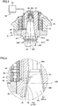
Fig. 2 is a sectional view showing the spindle end surface side of the spindle head inFig. 1 . With reference toFigs. 1 and2 ,spindle 43 is rotatably supported byspindle sleeve 42 through a plurality ofbearings 46. With reference toFig. 2 ,tool 200 is attached to spindle 43 while being clamped. -
Spindle 43 includes atool insertion portion 44.Tool insertion portion 44 has a shape of an opening into which a shank 201 (shank taperedportion 201s) oftool 200, which will be described below, is inserted.Tool insertion portion 44 has an opening surface which is open within the machining area and has a tubular opening shape extending from the opening surface along the axis ofcentral axis 101.Tool insertion portion 44 is open downward. -
Tool insertion portion 44 has a restrainingsurface 45. Restrainingsurface 45 is formed of a cylindrical inner circumferential surface extending aboutcentral axis 101 along the axis ofcentral axis 101. Restrainingsurface 45 has a tapered shape having a diameter changing along the axis ofcentral axis 101. -
Spindle 43 further includes atool clamping device 48.Tool clamping device 48 is configured to allowspindle 43 to clamptool 200. Causingtool clamping device 48 to perform a clamping operation clampstool 200 byspindle 43. Causingtool clamping device 48 to perform an unclamping operation unclampstool 200 fromspindle 43. - As one example,
tool clamping device 48 is used that includes a collet capable of graspingtool 200, a drawbar that moves back and forth along the axis ofcentral axis 101 to open and close the collet, a disc spring fitted into the drawbar, and a hydraulic mechanism that exerts an oil pressure on the drawbar. In this case, a clamping force for clampingtool 200 is obtained by the spring force of the disc spring, and an unclamping force for unclampingtool 200 is obtained by the oil pressure generated in the hydraulic mechanism. -
Tool 200 includesshank 201, apull stud 202, and ablade 203.Shank 201 is formed of a shank taperedportion 201s and a shankflanged portion 201t. - Shank
tapered portion 201s has a tapered shape with a diameter changing along the axis ofcentral axis 101. Shanktapered portion 201s is brought into surface contact with restrainingsurface 45 oftool insertion portion 44 whentool 200 is clamped. This bringstool 200 to surface restraint withspindle 43. Shankflanged portion 201t has a shape extending from one end of shank taperedportion 201s in the axial direction ofcentral axis 101 like a collar. Shankflanged portion 201t is gripped bygripper 32p andgripper 32q of ATCmain arm 32 in automatic tool change oftool 200. - Pull
stud 202 is connected to the other end of shank taperedportion 201s in the axial direction ofcentral axis 101. Pullstud 202 is pulled intospindle 43 along the axis ofcentral axis 101 by tool clamping device 48 (collet) whentool 200 is clamped. -
Machine tool 10 is a numerically control (NC) machine tool in which various operations for machining a workpiece are automated through numerical control by a computer. -
Machine tool 10 further includes acontroller 51.Controller 51 is a control board installed inmachine tool 10 for controlling the various operations in machine tool 1 0.Controller 51 controls, for example, sliding movements of various structures in three orthogonal axes (X axis, Y axis, Z axis), operations oftool magazine 21 andtool change unit 31, and an air purge operation by anair supply unit 61, which will be described below. -
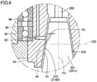
Figs. 3 and4 are sectional views showing an air purge step for a tool in automatic tool change.Figs. 3 and4 show an enlarged range surrounded by a chain double-dashed line III inFig. 2 . - With reference to
Figs. 1 and4 ,machine tool 10 further includesair supply unit 61.Air supply unit 61 is configured to supply air to agap 210 betweentool insertion portion 44 ofspindle 43 andshank 201 oftool 200 in automatic tool change. -
Air supply unit 61 includes anair compressor 63, anair circulation hole 62, and a valve (not shown).Air circulation hole 62 is provided inspindle 43.Air circulation hole 62 is open on restrainingsurface 45.Air circulation hole 62 may be open at a plurality of spots of restrainingsurface 45.Air compressor 63 is configured to supply compressed air.Air circulation hole 62 is supplied with the air fromair compressor 63. The valve is provided on a path of the air supplied fromair compressor 63. - When the valve is opened, air is injected from
air circulation hole 62 towardgap 210. The air passes throughgap 210 toward the spindle end surface, thereby removing chips adhering totool 200. When the valve is closed, the ejection of the air fromair circulation hole 62 towardgap 210 is stopped. -
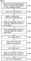
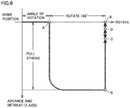
Fig. 5 is a flowchart showing a flow of steps of automatic tool change and air purge.Fig. 6 is a graph showing movements (advancing and retreating motions, turning motion) of an ATC main arm in automatic tool change.Fig. 7 is a graph showing changes in the speed of a tool in automatic tool change. InFig. 7 , the speed oftool 200 during ascent is indicated by a minus sign, and the speed oftool 200 during descent is indicated by a plus sign. - With reference to
Figs. 1 to 7 , description will be given of an automatic tool change step fortool 200 attached tospindle 43 and an air purge step fortool 200 which is performed byspindle 43 along with the automatic tool change. - At step S101 in
Fig. 5 , first,tool 200 intool magazine 21 is moved to a standby position, and also,spindle 43 is moved to a tool change position. - In
tool magazine 21, atool pot 22 to which atool 200K to be used in machining of a next workpiece is attached is transferred to a position (indexing position) of opening 25 which is provided incover body 24.Tool pot 22 is rotated 90° by a turning mechanism (not shown) to move from the indexing position to the standby position. Whiletool pot 22 is located at the standby position, the central axis oftool 200K held bytool pot 22 is a direction (Z axis direction) parallel tocentral axis 101 andcentral axis 102. -
Spindle 43 with atool 200J attached thereto is moved to the tool change position adjacent to the standby position oftool pot 22 after machining of theworkpiece using tool 200J is complete. - At step S102 in
Fig. 5 , then, with a shutter (not shown) open, which separates an area within the machining area from an area outside the machining area, ATCmain arm 32 is rotated 90° from a home position (a position at which ATCmain arm 32 extends along the Y axis like an arm). - At this time,
gripper 32p grips tool 200J attached tospindle 43, andgripper 32q gripstool 200K held bytool pot 22 located at the standby position (the state shown inFig. 1 ). Clamping oftool 200J inspindle 43 is released at a timing at whichtool 200J is gripped bygripper 32p. - At step S103 in
Fig. 5 , then, ATCmain arm 32 is lowered, and also, ATCmain arm 32 is rotated 180° (corresponding to position A → position B inFig. 6 ). - Consequently,
tool 200J is pulled out ofspindle 43, andtool 200K is pulled out oftool pot 22. Simultaneously,tool 200J is moved to a position at whichtool 200J facestool pot 22 in the Z axis direction, andtool 200K is moved to a position at whichtool 200K facesspindle 43 in the Z axis direction. - At step S104 in
Fig. 5 , then, ATCmain arm 32 is raised to move to the air-blow lower end position (corresponding to position B → position C inFig. 6 , time t1 → time t2 inFig. 7 ). - At this time, ATC
main arm 32 is moved at a speed V2.Fig. 3 showstool 200 when ATCmain arm 32 has been moved to the air-blow lower end position (position C inFig. 6 ). Shanktapered portion 201s oftool 200 is inserted intotool insertion portion 44. A gap 210 (210C) is provided between shank taperedportion 201s and restrainingsurface 45 oftool insertion portion 44. Air is injected to gap 210 (210C) throughair circulation hole 62. - At step S105 in
Fig. 5 , then, ATCmain arm 32 is raised to move to the air-blow upper end position (corresponding to position C → position D inFig. 6 , time t2 → time t3 inFig. 7 ). - At this time, ATC
main arm 32 is moved at a speed VI, which is lower than speed V2 at the former step.Fig. 4 showstool 200 when ATCmain arm 32 has been moved to the air-blow upper end position (position D inFig. 6 ). A gap 210 (210D) is provided between shank taperedportion 201s and restrainingsurface 45 oftool insertion portion 44. -
Gap 210 has a ring shape formed aboutcentral axis 101 whengap 210 is cut in a plane orthogonal tocentral axis 101.Gap 210 has a ring shape with a constant ring width in the radial direction ofcentral axis 101. - As shown in
Figs. 3 and4 , the size ofgap 210D is smaller than the size of gap 210C. The area ofgap 210D obtained whengap 210D is cut in anappropriate plane 220 orthogonal tocentral axis 101 is smaller than the area of gap 210C obtained when gap 210C is cut in thesame plane 220. Onplane 220, a length (ring width) R1 ofgap 210D in the radial direction ofcentral axis 101 is smaller than a length (ring width) R2 of gap 210C in the radial direction ofcentral axis 101. - At step S106 in
Fig. 5 , then, ATCmain arm 32 is stopped at the air-blow upper end position for a certain period of time (corresponding to time t3 → time t4 inFig. 7 ). - At step S107 in
Fig. 5 , then, ATCmain arm 32 is repeatedly raised and lowered between the air-blow upper end position and the air-blow lower end position (corresponding to position D → position C → position D → position C → ... inFig. 6 , time t4 to time t9 inFig. 7 ). - At this time, ATC
main arm 32 is repeatedly raised and lowered at speed V1. Withshank 201 oftool 200K inserted intotool insertion portion 44 and withgap 210 provided betweentool insertion portion 44 andshank 201 oftool 200K,tool 200K reciprocates along the Z axis relative totool insertion portion 44. - At the above step, the distance between the air-blow upper end position (position D) and the air-blow lower end position (position C) and the cycle in which
tool 200K is reciprocated are preferably set to achieve a phenomenon in whichtool 200K slightly vibrates in the Z axis direction. - The distance between the air-blow upper end position (position D) and the air-blow lower end position (position C) is not particularly limited, which may be in the range of 0.5 mm or more and 5 mm or less or in the range of 1 mm or more and 3 mm or less.
- At step S108 in
Fig. 5 , then, ATCmain arm 32 is stopped at the air-blow upper end position for a certain period of time (corresponding to time t9 → time t10 inFig. 7 ). - At step S109 in
Fig. 5 , then, ATCmain arm 32 is raised to move to an insertion complete position (corresponding to position D → position E inFig. 6 , time t10 → time t11 inFig. 7 ). At this time, ATCmain arm 32 is raised at speed V1.Tool 200K is clamped inspindle 43. - At step S110 in
Fig. 5 , then, ATCmain arm 32 is rotated 90° to return to its home position. Through the above steps, automatic tool change oftool 200 attached tospindle 43 is complete. - In
machine tool 10 in the present embodiment,controller 51 controls driving oftool change unit 31 such thattool 200 reciprocates relative totool insertion portion 44 in a predetermined direction withshank 201 oftool 200 inserted intotool insertion portion 44 and withgap 210 provided betweentool insertion portion 44 andshank 201 oftool 200. - With such a configuration, the speed of an airflow in
gap 210 changes momentarily due to repetitive increase and decrease in the size ofgap 210 which are caused by the reciprocating motion oftool 200. This causes turbulence in an airflow ingap 210, thereby efficiently removing chips adhering totool 200. - The predetermined direction in which
tool 200 reciprocates relative totool insertion portion 44 is the direction (Z axis direction) of insertion ofshank 201 oftool 200 intotool insertion portion 44. - With such a configuration, a length (ring width) of
gap 210 in the radial direction ofcentral axis 101 is uniform circumferentially aboutcentral axis 101, which makes it difficult for restrainingsurface 45 oftool insertion portion 44 and shank taperedportion 201s oftool 200 to interfere with each other. Also, an effect of efficiently removing chips adhering totool 200 can be uniformly achieved circumferentially aboutcentral axis 101. -
Controller 51 also controls driving oftool change unit 31 to perform the step (corresponding to S105) of insertingshank 201 oftool 200 intotool insertion portion 44 in one direction and stopping the insertion ofshank 201 oftool 200 intotool insertion portion 44 at a first position (position D inFig. 6 ) at whichgap 210 is generated betweentool insertion portion 44 andshank 201 oftool 200 and the step (corresponding to S107) ofreciprocating tool 200 relative totool insertion portion 44 between the first position (position D inFig. 6 ) and a second position (position C inFig. 6 ) opposite to the direction of insertion ofshank 201 oftool 200 as viewed from the first position (position D inFig. 6 ). - With such a configuration, after
tool insertion portion 44 is stopped at the first position at whichgap 210 is generated at step S105, at step S107,tool 200 is reciprocated between the first position and the second position located in the direction in whichgap 210 increases as viewed from the first position. This makes it further difficult for restrainingsurface 45 oftool insertion portion 44 and shank taperedportion 201s oftool 200 to interfere with each other. - At step S107, spindle 43 (spindle head 41) may be raised and lowered when
tool 200 is reciprocated relative totool insertion portion 44.Tool 200 andtool insertion portion 44 may be reciprocated relative to each other in an up-down direction by simultaneously raising and lowering ATCmain arm 32 and raising and lowering spindle 43 (spindle head 41). - A machine tool to which the present invention is applied is not limited to a vertical machining center and may be a horizontal machining center or a multitasking machine having a turning function and a milling function.
- The present embodiment will describe various modifications of the manner of reciprocating
tool 200 andtool insertion portion 44 relative to each other at step S107 inFig. 5 . -
Fig. 8 is a sectional view showing a first modification of the manner of reciprocating a tool and a tool insertion portion relative to each other.Fig. 8 schematically shows a cross-section ofspindle head 41 cut in a plane orthogonal tocentral axis 101. - With reference to
Figs. 1 and8 , at step S107 inFig. 5 , ATCmain arm 32 is rotated alternately in the forward direction and reverse direction aboutcentral axis 102. This causestool 200 to reciprocate relative totool insertion portion 44 circumferentially aboutcentral axis 102 between a tool center position P and a tool center position Q. -
Fig. 9 is a sectional view showing a second modification of the manner of reciprocating a tool and a tool insertion portion relative to each other.Fig. 9 schematically shows a cross-section ofspindle head 41 cut in a plane orthogonal tocentral axis 101. In the present modification,spindle head 41 is configured to be movable in a horizontal plane (X-axis-Y-axis plane). - With reference to
Figs. 1 and9 , at step S107 inFig. 5 , spindle 43 (spindle head 41) is moved to describe a circumference about tool center P oftool 200 in the horizontal plane (X-axis-Y-axis plane). This causestool insertion portion 44 to reciprocate relative totool 200 circumferentially about tool center P between aspindle center position 101A and aspindle center position 101B. - In the modifications shown in
Figs. 8 and 9 , the predetermined direction in whichtool 200 andtool insertion portion 44 reciprocate relative to each other is a direction parallel to the plane (X-axis-Y-axis plane) orthogonal to the direction of insertion ofshank 201 intotool insertion portion 44. - The machine tool according to Embodiment 2 of the present invention configured as described above can achieve effects similar to those described in Embodiment 1.
- The configuration of the present invention and the functions and effects achieved by the present invention will be summarized below.
- A machine tool according to the present invention includes a tool attachment unit, a tool change unit, an air supply unit, and a controller. The tool attachment unit includes a tool insertion portion having a shape of an opening into which a shank of a tool is inserted. The tool attachment unit is configured to attach a tool thereto. The tool change unit changes the tool attached to the tool attachment unit while gripping the tool. The air supply unit is configured to supply air to a gap between the tool insertion portion and the shank of the tool when the tool change unit changes the tool. The controller is configured to control driving of at least any one of the tool attachment unit and the tool change unit to allow the tool and the tool insertion portion to reciprocate relative to each other in a predetermined direction with the shank of the tool inserted into the tool insertion portion and with a gap provided between the tool insertion portion and the shank of the tool.
- The machine tool configured as described above reciprocates the tool and the tool insertion portion relative to each other in the predetermined direction, thereby causing turbulence in an airflow flowing through a gap between the tool insertion portion and the shank of the tool. This efficiently removes chips adhering to the tool.
- Preferably, the shank of the tool is inserted into the tool insertion portion from one direction. The predetermined direction is a direction of insertion of the shank of the tool.
- The machine tool configured as described above makes it difficult for the tool attachment unit and the shank of the tool to interfere with each other when the tool and the tool insertion portion are reciprocated relative to each other in the predetermined direction.
- Preferably, the controller controls driving of at least any one of the tool attachment unit and the tool change unit to perform the steps of inserting the shank of the tool into the tool insertion portion in one direction and stopping the insertion of the shank of the tool into the tool insertion portion at a first position at which a gap is generated between the tool insertion portion and the shank of the tool, and reciprocating the tool and the tool insertion portion relative to each other between the first position and a second position opposite to the direction of insertion of the shank of the tool as viewed from the first position.
- The machine tool configured as described above makes it further difficult for the tool attachment unit and the shank of the tool to interfere with each other when the tool and the tool insertion portion are reciprocated relative to each other in the predetermined direction.
- Preferably, the shank of the tool is inserted into the tool insertion portion from one direction. The predetermined direction is a direction parallel to a plane orthogonal to the direction of insertion of the shank of the tool.
- The machine tool configured as described above can change the size of the gap between the tool insertion portion and the shank of the tool in the plane orthogonal to the direction of insertion of the shank of the tool. This causes turbulence in an airflow flowing through the gap.
- The present invention is applied to a machine tool including an air purge mechanism for a tool during automatic tool change.
- Although the present invention has been described and illustrated in detail, it is clearly understood that the same is by way of illustration and example only and is not to be taken by way of limitation, the scope of the present invention being interpreted by the terms of the appended claims.
Claims (4)
- A machine tool comprising:a tool attachment unit (43) including a tool insertion portion (44) having a shape of an opening into which a shank (201) of a tool is inserted, the tool attachment unit (43) being configured to attach a tool thereto;a tool change unit (31) configured to change the tool attached to the tool attachment unit (43) while gripping the tool;an air supply unit (61) configured to supply air to a gap (210) between the tool insertion portion (44) and the shank (201) of the tool when the tool change unit (31) changes the tool; anda controller (51) configured to control driving of at least any one of the tool attachment unit (43) and the tool change unit (31) to allow the tool and the tool insertion portion (44) to reciprocate relative to each other in a predetermined direction with the shank (201) of the tool inserted into the tool insertion portion (44) and with a gap (210) provided between the tool insertion portion (44) and the shank (201) of the tool.
- The machine tool according to claim 1, wherein
the shank (201) of the tool is inserted into the tool insertion portion (44) from one direction, and
the predetermined direction is a direction of insertion of the shank (201) of the tool. - The machine tool according to claim 2, wherein the controller (51) controls at least any one of the tool attachment unit (43) and the tool change unit (31) to perform the steps of
inserting the shank (201) of the tool into the tool insertion portion (44) in one direction and stopping the insertion of the shank (201) of the tool into the tool insertion portion (44) at a first position at which the gap (210) is generated between the tool insertion portion (44) and the shank (201) of the tool, and
reciprocating the tool and the tool insertion portion (44) relative to each other between the first position and a second position opposite to the direction of insertion of the shank (201) of the tool as viewed from the first position. - The machine tool according to claim 1, wherein
the shank (201) of the tool is inserted into the tool insertion portion (44) from one direction, and
the predetermined direction is a direction parallel to a plane orthogonal to a direction of insertion of the shank (201) of the tool.
Applications Claiming Priority (1)
| Application Number | Priority Date | Filing Date | Title |
|---|---|---|---|
| JP2018072333A JP6688829B2 (en) | 2018-04-04 | 2018-04-04 | Machine Tools |
Publications (2)
| Publication Number | Publication Date |
|---|---|
| EP3549716A1 EP3549716A1 (en) | 2019-10-09 |
| EP3549716B1 true EP3549716B1 (en) | 2021-01-27 |
Family
ID=66223609
Family Applications (1)
| Application Number | Title | Priority Date | Filing Date |
|---|---|---|---|
| EP19166844.1A Active EP3549716B1 (en) | 2018-04-04 | 2019-04-02 | Machine tool |
Country Status (4)
| Country | Link |
|---|---|
| US (1) | US10792735B2 (en) |
| EP (1) | EP3549716B1 (en) |
| JP (1) | JP6688829B2 (en) |
| CN (1) | CN110340721B (en) |
Families Citing this family (3)
| Publication number | Priority date | Publication date | Assignee | Title |
|---|---|---|---|---|
| JP6737847B2 (en) * | 2018-07-31 | 2020-08-12 | ファナック株式会社 | Spindle device |
| JP6998288B2 (en) * | 2018-10-31 | 2022-01-18 | 日精ホンママシナリー株式会社 | Spindle for rotary tools with tool seating confirmation function |
| CN113894299B (en) * | 2021-09-30 | 2022-12-06 | 珠海格力电器股份有限公司 | Main shaft gas cleaning device |
Family Cites Families (29)
| Publication number | Priority date | Publication date | Assignee | Title |
|---|---|---|---|---|
| DE2754636A1 (en) * | 1977-12-08 | 1979-06-13 | Droop & Rein | Endless tool magazine for machine tool - has tapered shanks of cutting tools cleaned by blast of air through perforations in conical wall |
| JPS60172B2 (en) * | 1981-12-21 | 1985-01-07 | 東芝機械株式会社 | Main spindle structure of vertical lathe |
| US4504824A (en) * | 1982-11-17 | 1985-03-12 | Houdaille Industries, Inc. | Tool detection system |
| DE3930070C2 (en) * | 1989-09-09 | 1993-12-16 | Chiron Werke Gmbh | Machine tool with blow-out tool holder |
| JP2852561B2 (en) * | 1990-10-24 | 1999-02-03 | 株式会社森精機製作所 | Tool holder of spindle unit with automatic tool changer |
| JPH0529656U (en) * | 1991-09-30 | 1993-04-20 | 豊田工機株式会社 | Machine tool tool for removing chips from spindle |
| JPH07285046A (en) * | 1994-04-19 | 1995-10-31 | Hitachi Seiki Co Ltd | Method and device for attaching tool to machine tool |
| JPH0957582A (en) * | 1995-08-11 | 1997-03-04 | Kitamura Mach Co Ltd | Main spindle device |
| JPH1190762A (en) * | 1997-05-27 | 1999-04-06 | Chiron Werke Gmbh & Co Kg | Machine tool |
| JPH11138382A (en) * | 1997-11-12 | 1999-05-25 | Okuma Corp | Main spindle device |
| JP3055019B1 (en) * | 1999-02-22 | 2000-06-19 | ホーコス株式会社 | Chip suction type machine tool |
| JP2000308935A (en) * | 1999-04-28 | 2000-11-07 | Howa Mach Ltd | Tool replacing device and device and machine tool |
| TW431251U (en) * | 2000-01-29 | 2001-04-21 | Sun Ho Wei | Automatic blowing device for spindle releasing and holding cutting tools of cutting machine center |
| US20020045521A1 (en) * | 2000-10-16 | 2002-04-18 | Hideki Mochida | Spindle unit for a machine tool |
| US6939094B2 (en) * | 2003-01-28 | 2005-09-06 | Macro Technologies Inc. | Autonomous power interface for modifying limited rotation speed of a machine |
| JP3764432B2 (en) | 2003-03-06 | 2006-04-05 | ファナック株式会社 | Tool chip prevention / removal method and tool changer |
| JP2005081489A (en) * | 2003-09-08 | 2005-03-31 | Nippei Toyama Corp | Cleaning method and device of tool holder fitting part of spindle device in machine tool |
| JP3883996B2 (en) * | 2003-09-30 | 2007-02-21 | 三洋化成工業株式会社 | Flame retardant for polyester synthetic fiber |
| US7568867B2 (en) * | 2006-10-18 | 2009-08-04 | Bryan Steve M | Air driven spindle assembly |
| JP4764450B2 (en) * | 2008-03-31 | 2011-09-07 | 三菱重工業株式会社 | Tool contact state detection device for machine tools |
| JP2010105088A (en) * | 2008-10-29 | 2010-05-13 | Mazda Motor Corp | Device for removing swarf from machine tool |
| IN2012DN03874A (en) * | 2009-11-18 | 2015-09-25 | Komatsu Ntc Ltd | |
| US9162335B2 (en) * | 2012-01-20 | 2015-10-20 | Air Turbine Technology, Inc. | Auto changer spindle mounting assembly |
| US9375816B2 (en) * | 2012-07-11 | 2016-06-28 | Air Turbine Technology, Inc. | Auto changer spindle mounting assembly adapted to drill tap machines |
| JP6314066B2 (en) * | 2014-09-08 | 2018-04-18 | Dmg森精機株式会社 | Machine Tools |
| JP3198538U (en) * | 2015-04-17 | 2015-07-09 | 株式会社アーレスティ | Blade tool gripping device |
| JP6306617B2 (en) * | 2016-01-05 | 2018-04-04 | ファナック株式会社 | Machine tool with chip discharge device |
| CN206643615U (en) * | 2016-12-13 | 2017-11-17 | 宁波海天精工股份有限公司 | A kind of function switching structure for being applied to main shaft tool changing air blowing and central water outlet |
| JP6297128B1 (en) * | 2016-12-16 | 2018-03-20 | Dmg森精機株式会社 | Machine Tools |
-
2018
- 2018-04-04 JP JP2018072333A patent/JP6688829B2/en active Active
-
2019
- 2019-03-27 US US16/365,838 patent/US10792735B2/en active Active
- 2019-04-02 EP EP19166844.1A patent/EP3549716B1/en active Active
- 2019-04-03 CN CN201910267046.2A patent/CN110340721B/en active Active
Non-Patent Citations (1)
| Title |
|---|
| None * |
Also Published As
| Publication number | Publication date |
|---|---|
| JP2019181590A (en) | 2019-10-24 |
| CN110340721A (en) | 2019-10-18 |
| JP6688829B2 (en) | 2020-04-28 |
| EP3549716A1 (en) | 2019-10-09 |
| US20190308251A1 (en) | 2019-10-10 |
| CN110340721B (en) | 2022-03-15 |
| US10792735B2 (en) | 2020-10-06 |
Similar Documents
| Publication | Publication Date | Title |
|---|---|---|
| EP3549716B1 (en) | Machine tool | |
| JP5497582B2 (en) | Horizontal machining center | |
| EP2992996B1 (en) | Machine tool | |
| KR102391258B1 (en) | Machine tool | |
| CN108655802B (en) | Machine tool system and moving method | |
| EP1629921B1 (en) | Electric discharge machine and machining method therefor | |
| US20160243661A1 (en) | Machine tool | |
| US6832433B2 (en) | Machining apparatus and method of using same | |
| CN109623013A (en) | The method of numeric control drilling machine tool and guiding device and replacement numeric control drilling machine tool cutter | |
| CN216421836U (en) | Be applied to manipulator and lathe of lathe | |
| JP2009516596A (en) | Cutting tool feeder for internal cutting | |
| CN210280789U (en) | Guider and numerical control drilling machine tool for numerical control drilling machine tool | |
| JP3235067B2 (en) | Automatic drill changer for drilling robot | |
| JP2551292B2 (en) | Cutting equipment | |
| CN220497781U (en) | Double-end numerical control lathe special for finish machining of short parts | |
| JP2666643B2 (en) | Cutting equipment | |
| KR200381781Y1 (en) | Boring apparatus for cylinder of air conditioner | |
| JP2003094276A (en) | Machine tool, tool, tool holder, and machining method using the same | |
| JPS62148129A (en) | Five spindle type controlled machining device | |
| JP2006212745A (en) | Lathe and machining method | |
| JP4130733B2 (en) | Machine Tools | |
| KR20240014747A (en) | Machine tool equipped with parts handling device | |
| SU1349969A1 (en) | Automated manufacturing unit | |
| JPH0890303A (en) | Numerically controlled automatic lathe | |
| JPS62148131A (en) | Workpiece clamping method with use of machining spindle |
Legal Events
| Date | Code | Title | Description |
|---|---|---|---|
| PUAI | Public reference made under article 153(3) epc to a published international application that has entered the european phase |
Free format text: ORIGINAL CODE: 0009012 |
|
| STAA | Information on the status of an ep patent application or granted ep patent |
Free format text: STATUS: THE APPLICATION HAS BEEN PUBLISHED |
|
| AK | Designated contracting states |
Kind code of ref document: A1 Designated state(s): AL AT BE BG CH CY CZ DE DK EE ES FI FR GB GR HR HU IE IS IT LI LT LU LV MC MK MT NL NO PL PT RO RS SE SI SK SM TR |
|
| AX | Request for extension of the european patent |
Extension state: BA ME |
|
| STAA | Information on the status of an ep patent application or granted ep patent |
Free format text: STATUS: REQUEST FOR EXAMINATION WAS MADE |
|
| 17P | Request for examination filed |
Effective date: 20200409 |
|
| RBV | Designated contracting states (corrected) |
Designated state(s): AL AT BE BG CH CY CZ DE DK EE ES FI FR GB GR HR HU IE IS IT LI LT LU LV MC MK MT NL NO PL PT RO RS SE SI SK SM TR |
|
| GRAP | Despatch of communication of intention to grant a patent |
Free format text: ORIGINAL CODE: EPIDOSNIGR1 |
|
| STAA | Information on the status of an ep patent application or granted ep patent |
Free format text: STATUS: GRANT OF PATENT IS INTENDED |
|
| INTG | Intention to grant announced |
Effective date: 20201016 |
|
| GRAS | Grant fee paid |
Free format text: ORIGINAL CODE: EPIDOSNIGR3 |
|
| GRAA | (expected) grant |
Free format text: ORIGINAL CODE: 0009210 |
|
| STAA | Information on the status of an ep patent application or granted ep patent |
Free format text: STATUS: THE PATENT HAS BEEN GRANTED |
|
| AK | Designated contracting states |
Kind code of ref document: B1 Designated state(s): AL AT BE BG CH CY CZ DE DK EE ES FI FR GB GR HR HU IE IS IT LI LT LU LV MC MK MT NL NO PL PT RO RS SE SI SK SM TR |
|
| REG | Reference to a national code |
Ref country code: GB Ref legal event code: FG4D |
|
| REG | Reference to a national code |
Ref country code: CH Ref legal event code: EP |
|
| REG | Reference to a national code |
Ref country code: AT Ref legal event code: REF Ref document number: 1357905 Country of ref document: AT Kind code of ref document: T Effective date: 20210215 |
|
| REG | Reference to a national code |
Ref country code: IE Ref legal event code: FG4D |
|
| REG | Reference to a national code |
Ref country code: DE Ref legal event code: R096 Ref document number: 602019002318 Country of ref document: DE |
|
| REG | Reference to a national code |
Ref country code: NL Ref legal event code: MP Effective date: 20210127 |
|
| REG | Reference to a national code |
Ref country code: LT Ref legal event code: MG9D |
|
| REG | Reference to a national code |
Ref country code: AT Ref legal event code: MK05 Ref document number: 1357905 Country of ref document: AT Kind code of ref document: T Effective date: 20210127 |
|
| PG25 | Lapsed in a contracting state [announced via postgrant information from national office to epo] |
Ref country code: PT Free format text: LAPSE BECAUSE OF FAILURE TO SUBMIT A TRANSLATION OF THE DESCRIPTION OR TO PAY THE FEE WITHIN THE PRESCRIBED TIME-LIMIT Effective date: 20210527 Ref country code: NO Free format text: LAPSE BECAUSE OF FAILURE TO SUBMIT A TRANSLATION OF THE DESCRIPTION OR TO PAY THE FEE WITHIN THE PRESCRIBED TIME-LIMIT Effective date: 20210427 Ref country code: LT Free format text: LAPSE BECAUSE OF FAILURE TO SUBMIT A TRANSLATION OF THE DESCRIPTION OR TO PAY THE FEE WITHIN THE PRESCRIBED TIME-LIMIT Effective date: 20210127 Ref country code: BG Free format text: LAPSE BECAUSE OF FAILURE TO SUBMIT A TRANSLATION OF THE DESCRIPTION OR TO PAY THE FEE WITHIN THE PRESCRIBED TIME-LIMIT Effective date: 20210427 Ref country code: FI Free format text: LAPSE BECAUSE OF FAILURE TO SUBMIT A TRANSLATION OF THE DESCRIPTION OR TO PAY THE FEE WITHIN THE PRESCRIBED TIME-LIMIT Effective date: 20210127 Ref country code: GR Free format text: LAPSE BECAUSE OF FAILURE TO SUBMIT A TRANSLATION OF THE DESCRIPTION OR TO PAY THE FEE WITHIN THE PRESCRIBED TIME-LIMIT Effective date: 20210428 Ref country code: HR Free format text: LAPSE BECAUSE OF FAILURE TO SUBMIT A TRANSLATION OF THE DESCRIPTION OR TO PAY THE FEE WITHIN THE PRESCRIBED TIME-LIMIT Effective date: 20210127 |
|
| PG25 | Lapsed in a contracting state [announced via postgrant information from national office to epo] |
Ref country code: SE Free format text: LAPSE BECAUSE OF FAILURE TO SUBMIT A TRANSLATION OF THE DESCRIPTION OR TO PAY THE FEE WITHIN THE PRESCRIBED TIME-LIMIT Effective date: 20210127 Ref country code: PL Free format text: LAPSE BECAUSE OF FAILURE TO SUBMIT A TRANSLATION OF THE DESCRIPTION OR TO PAY THE FEE WITHIN THE PRESCRIBED TIME-LIMIT Effective date: 20210127 Ref country code: LV Free format text: LAPSE BECAUSE OF FAILURE TO SUBMIT A TRANSLATION OF THE DESCRIPTION OR TO PAY THE FEE WITHIN THE PRESCRIBED TIME-LIMIT Effective date: 20210127 Ref country code: RS Free format text: LAPSE BECAUSE OF FAILURE TO SUBMIT A TRANSLATION OF THE DESCRIPTION OR TO PAY THE FEE WITHIN THE PRESCRIBED TIME-LIMIT Effective date: 20210127 Ref country code: AT Free format text: LAPSE BECAUSE OF FAILURE TO SUBMIT A TRANSLATION OF THE DESCRIPTION OR TO PAY THE FEE WITHIN THE PRESCRIBED TIME-LIMIT Effective date: 20210127 |
|
| PG25 | Lapsed in a contracting state [announced via postgrant information from national office to epo] |
Ref country code: IS Free format text: LAPSE BECAUSE OF FAILURE TO SUBMIT A TRANSLATION OF THE DESCRIPTION OR TO PAY THE FEE WITHIN THE PRESCRIBED TIME-LIMIT Effective date: 20210527 |
|
| REG | Reference to a national code |
Ref country code: DE Ref legal event code: R097 Ref document number: 602019002318 Country of ref document: DE |
|
| PG25 | Lapsed in a contracting state [announced via postgrant information from national office to epo] |
Ref country code: CZ Free format text: LAPSE BECAUSE OF FAILURE TO SUBMIT A TRANSLATION OF THE DESCRIPTION OR TO PAY THE FEE WITHIN THE PRESCRIBED TIME-LIMIT Effective date: 20210127 Ref country code: EE Free format text: LAPSE BECAUSE OF FAILURE TO SUBMIT A TRANSLATION OF THE DESCRIPTION OR TO PAY THE FEE WITHIN THE PRESCRIBED TIME-LIMIT Effective date: 20210127 Ref country code: SM Free format text: LAPSE BECAUSE OF FAILURE TO SUBMIT A TRANSLATION OF THE DESCRIPTION OR TO PAY THE FEE WITHIN THE PRESCRIBED TIME-LIMIT Effective date: 20210127 |
|
| PG25 | Lapsed in a contracting state [announced via postgrant information from national office to epo] |
Ref country code: DK Free format text: LAPSE BECAUSE OF FAILURE TO SUBMIT A TRANSLATION OF THE DESCRIPTION OR TO PAY THE FEE WITHIN THE PRESCRIBED TIME-LIMIT Effective date: 20210127 Ref country code: SK Free format text: LAPSE BECAUSE OF FAILURE TO SUBMIT A TRANSLATION OF THE DESCRIPTION OR TO PAY THE FEE WITHIN THE PRESCRIBED TIME-LIMIT Effective date: 20210127 Ref country code: RO Free format text: LAPSE BECAUSE OF FAILURE TO SUBMIT A TRANSLATION OF THE DESCRIPTION OR TO PAY THE FEE WITHIN THE PRESCRIBED TIME-LIMIT Effective date: 20210127 Ref country code: MC Free format text: LAPSE BECAUSE OF FAILURE TO SUBMIT A TRANSLATION OF THE DESCRIPTION OR TO PAY THE FEE WITHIN THE PRESCRIBED TIME-LIMIT Effective date: 20210127 |
|
| PLBE | No opposition filed within time limit |
Free format text: ORIGINAL CODE: 0009261 |
|
| STAA | Information on the status of an ep patent application or granted ep patent |
Free format text: STATUS: NO OPPOSITION FILED WITHIN TIME LIMIT |
|
| PG25 | Lapsed in a contracting state [announced via postgrant information from national office to epo] |
Ref country code: LU Free format text: LAPSE BECAUSE OF NON-PAYMENT OF DUE FEES Effective date: 20210402 |
|
| 26N | No opposition filed |
Effective date: 20211028 |
|
| REG | Reference to a national code |
Ref country code: BE Ref legal event code: MM Effective date: 20210430 |
|
| PG25 | Lapsed in a contracting state [announced via postgrant information from national office to epo] |
Ref country code: AL Free format text: LAPSE BECAUSE OF FAILURE TO SUBMIT A TRANSLATION OF THE DESCRIPTION OR TO PAY THE FEE WITHIN THE PRESCRIBED TIME-LIMIT Effective date: 20210127 Ref country code: FR Free format text: LAPSE BECAUSE OF NON-PAYMENT OF DUE FEES Effective date: 20210430 Ref country code: ES Free format text: LAPSE BECAUSE OF FAILURE TO SUBMIT A TRANSLATION OF THE DESCRIPTION OR TO PAY THE FEE WITHIN THE PRESCRIBED TIME-LIMIT Effective date: 20210127 |
|
| PG25 | Lapsed in a contracting state [announced via postgrant information from national office to epo] |
Ref country code: SI Free format text: LAPSE BECAUSE OF FAILURE TO SUBMIT A TRANSLATION OF THE DESCRIPTION OR TO PAY THE FEE WITHIN THE PRESCRIBED TIME-LIMIT Effective date: 20210127 |
|
| PG25 | Lapsed in a contracting state [announced via postgrant information from national office to epo] |
Ref country code: IT Free format text: LAPSE BECAUSE OF FAILURE TO SUBMIT A TRANSLATION OF THE DESCRIPTION OR TO PAY THE FEE WITHIN THE PRESCRIBED TIME-LIMIT Effective date: 20210127 Ref country code: IE Free format text: LAPSE BECAUSE OF NON-PAYMENT OF DUE FEES Effective date: 20210402 |
|
| PG25 | Lapsed in a contracting state [announced via postgrant information from national office to epo] |
Ref country code: IS Free format text: LAPSE BECAUSE OF FAILURE TO SUBMIT A TRANSLATION OF THE DESCRIPTION OR TO PAY THE FEE WITHIN THE PRESCRIBED TIME-LIMIT Effective date: 20210527 |
|
| PG25 | Lapsed in a contracting state [announced via postgrant information from national office to epo] |
Ref country code: BE Free format text: LAPSE BECAUSE OF NON-PAYMENT OF DUE FEES Effective date: 20210430 |
|
| REG | Reference to a national code |
Ref country code: CH Ref legal event code: PL |
|
| PG25 | Lapsed in a contracting state [announced via postgrant information from national office to epo] |
Ref country code: LI Free format text: LAPSE BECAUSE OF NON-PAYMENT OF DUE FEES Effective date: 20220430 Ref country code: CH Free format text: LAPSE BECAUSE OF NON-PAYMENT OF DUE FEES Effective date: 20220430 |
|
| PG25 | Lapsed in a contracting state [announced via postgrant information from national office to epo] |
Ref country code: NL Free format text: LAPSE BECAUSE OF NON-PAYMENT OF DUE FEES Effective date: 20210127 Ref country code: CY Free format text: LAPSE BECAUSE OF FAILURE TO SUBMIT A TRANSLATION OF THE DESCRIPTION OR TO PAY THE FEE WITHIN THE PRESCRIBED TIME-LIMIT Effective date: 20210127 |
|
| PG25 | Lapsed in a contracting state [announced via postgrant information from national office to epo] |
Ref country code: HU Free format text: LAPSE BECAUSE OF FAILURE TO SUBMIT A TRANSLATION OF THE DESCRIPTION OR TO PAY THE FEE WITHIN THE PRESCRIBED TIME-LIMIT; INVALID AB INITIO Effective date: 20190402 |
|
| GBPC | Gb: european patent ceased through non-payment of renewal fee |
Effective date: 20230402 |
|
| PG25 | Lapsed in a contracting state [announced via postgrant information from national office to epo] |
Ref country code: GB Free format text: LAPSE BECAUSE OF NON-PAYMENT OF DUE FEES Effective date: 20230402 |
|
| PG25 | Lapsed in a contracting state [announced via postgrant information from national office to epo] |
Ref country code: GB Free format text: LAPSE BECAUSE OF NON-PAYMENT OF DUE FEES Effective date: 20230402 |
|
| PG25 | Lapsed in a contracting state [announced via postgrant information from national office to epo] |
Ref country code: MK Free format text: LAPSE BECAUSE OF FAILURE TO SUBMIT A TRANSLATION OF THE DESCRIPTION OR TO PAY THE FEE WITHIN THE PRESCRIBED TIME-LIMIT Effective date: 20210127 |
|
| PG25 | Lapsed in a contracting state [announced via postgrant information from national office to epo] |
Ref country code: TR Free format text: LAPSE BECAUSE OF FAILURE TO SUBMIT A TRANSLATION OF THE DESCRIPTION OR TO PAY THE FEE WITHIN THE PRESCRIBED TIME-LIMIT Effective date: 20210127 |
|
| PGFP | Annual fee paid to national office [announced via postgrant information from national office to epo] |
Ref country code: DE Payment date: 20240430 Year of fee payment: 6 |