EP3549691A1 - Production method for forged crankshaft - Google Patents
Production method for forged crankshaft Download PDFInfo
- Publication number
- EP3549691A1 EP3549691A1 EP17876386.8A EP17876386A EP3549691A1 EP 3549691 A1 EP3549691 A1 EP 3549691A1 EP 17876386 A EP17876386 A EP 17876386A EP 3549691 A1 EP3549691 A1 EP 3549691A1
- Authority
- EP
- European Patent Office
- Prior art keywords
- rough
- preform
- dies
- pins
- pressing
- Prior art date
- Legal status (The legal status is an assumption and is not a legal conclusion. Google has not performed a legal analysis and makes no representation as to the accuracy of the status listed.)
- Withdrawn
Links
Images


Classifications
-
- B—PERFORMING OPERATIONS; TRANSPORTING
- B21—MECHANICAL METAL-WORKING WITHOUT ESSENTIALLY REMOVING MATERIAL; PUNCHING METAL
- B21K—MAKING FORGED OR PRESSED METAL PRODUCTS, e.g. HORSE-SHOES, RIVETS, BOLTS OR WHEELS
- B21K1/00—Making machine elements
- B21K1/06—Making machine elements axles or shafts
- B21K1/08—Making machine elements axles or shafts crankshafts
-
- F—MECHANICAL ENGINEERING; LIGHTING; HEATING; WEAPONS; BLASTING
- F16—ENGINEERING ELEMENTS AND UNITS; GENERAL MEASURES FOR PRODUCING AND MAINTAINING EFFECTIVE FUNCTIONING OF MACHINES OR INSTALLATIONS; THERMAL INSULATION IN GENERAL
- F16C—SHAFTS; FLEXIBLE SHAFTS; ELEMENTS OR CRANKSHAFT MECHANISMS; ROTARY BODIES OTHER THAN GEARING ELEMENTS; BEARINGS
- F16C3/00—Shafts; Axles; Cranks; Eccentrics
- F16C3/04—Crankshafts, eccentric-shafts; Cranks, eccentrics
- F16C3/06—Crankshafts
- F16C3/08—Crankshafts made in one piece
-
- F—MECHANICAL ENGINEERING; LIGHTING; HEATING; WEAPONS; BLASTING
- F16—ENGINEERING ELEMENTS AND UNITS; GENERAL MEASURES FOR PRODUCING AND MAINTAINING EFFECTIVE FUNCTIONING OF MACHINES OR INSTALLATIONS; THERMAL INSULATION IN GENERAL
- F16C—SHAFTS; FLEXIBLE SHAFTS; ELEMENTS OR CRANKSHAFT MECHANISMS; ROTARY BODIES OTHER THAN GEARING ELEMENTS; BEARINGS
- F16C2220/00—Shaping
- F16C2220/40—Shaping by deformation without removing material
- F16C2220/46—Shaping by deformation without removing material by forging
Definitions
- the present invention relates to a method for producing a crankshaft, and more particularly to a method for producing a crankshaft by hot forging.
- a crankshaft is essential in a reciprocating engine for an automobile, a motorcycle, an agricultural machine, a ship, or the like to transform reciprocating movement of a piston into rotational movement for deriving power.
- a crankshaft can be produced either by die forging or casting.
- a crankshaft produced by die forging hereinafter referred to as a "forged crankshaft" is often used.
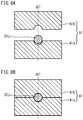
- FIGS. 1A and 1B are schematic diagrams to illustrate an exemplary shape of a typical forged crankshaft.
- FIG. 1A is a general view
- FIG. 1B is a sectional view along a line IB-IB.
- FIG. 1B representatively shows one crankarm A7, a counterweight W7 that is integral with the crankarm A7, and a pin P4 and a journal J4 that are connected to the crankarm A7.
- the crankshaft 11 shown in FIGS. 1A and 1B is a crankshaft of 4-cylinder 8-counterweight to be mounted on a 4-cylinder engine.
- the crankshaft 11 includes five journals J1 to J5, four pins P1 to P4, a front part Fr, a flange part Fl, and eight crankarms (hereinafter also referred to as "arms") A1 to A8.
- the arms A1 to A8 connect the journals J1 to J5 with the pins P1 to P4, respectively.
- all the eight arms A1 to A8 integrally include counterweights (hereinafter, also referred to as "weights”) W1 to W8, respectively.
- the front part Fr is located at a front end in the axial direction of the crankshaft 11, and the flange part Fl is located at a rear end thereof.
- the front part Fr is connected to the foremost first journal J1, and the flange part Fl is connected to the rearmost fifth journal J5.
- the pin top PT which is the tip of the pin P4 is, as shown in FIG. 1B , the part of the pin P4 farthest from the center of the journal J4.
- a billet is used as the starting material.
- a section perpendicular to the longitudinal direction of the billet that is, a cross section thereof has a circular or rectangular shape.
- the area of the cross section is constant over the entire length of the billet.
- cross section as used herein means a section perpendicular to the longitudinal direction of a billet or preform, or the axial direction of a crankshaft.
- longitudinal section means a section in parallel with the longitudinal direction or the axial direction.
- the area of a cross section is simply referred to as a "cross-sectional area”.
- a forged crankshaft is produced by performing a preforming process, a die forging process, and a flash-trimming process in that order. Moreover, as required, a coining process is performed after the flash-trimming process.
- the preforming process includes a roll forming process and a bend forging process.
- the die forging process includes a rough forging process and a finish forging process.
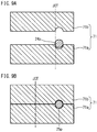
- FIGS. 2A to 2F are schematic diagrams to illustrate a conventional production process of a typical forged crankshaft.
- FIG. 2A shows a billet; FIG. 2B a rolled preform; FIG. 2C a bent preform; FIG. 2D a rough-forged product; FIG. 2E a finish-forged product; and FIG. 2F a forged crankshaft.
- FIGS. 2A to 2F show a production process for producing the crankshaft 11 having the shape shown in FIGS. 1A and 1B .
- a billet 12 having a predetermined length as shown in FIG. 2A is heated in a heating furnace and thereafter subjected to roll forming and bend forging in that order in the preforming process.
- the billet 12 is rolled by use of, for example, a grooved roll, and thereby the billet 12 is reduced. Accordingly, the volume of the billet 12 is distributed in the axial direction, and a rolled preform 13 is obtained as an intermediate starting material (see FIG. 2B ).
- the bend forging the rolled preform 13 is partly pressed in a direction perpendicular to the axial direction. Thereby, the volume of the rolled preform 13 is distributed, and a bent preform 14 is obtained as a further intermediate starting material (see FIG. 2C ).
- the bent preform 14 is forged by use of a vertical pair of dies, and thereby, the bent preform 14 is formed into a rough-forged product 15 (see FIG. 2D ).
- the resulting rough-forged product 15 has an approximate shape of the crankshaft (final product).
- the finish forging process the rough-forged product 15 is forged by use of a vertical pair of dies, and thereby, the rough-forged product 15 is formed into a finish-forged product 16 (see FIG. 2E ).
- the resulting finish-forged product 16 has a shape corresponding to that of the crankshaft as the final product.
- excess material flows out from between die parting surfaces of mutually opposed dies, and forms flash B. Therefore, each of the rough-forged product 15 and the finish-forged product 16 has pronounced flash B around its circumference.
- the flash B is punched off by use of a tool die. Thereby, the flash B is removed from the finish-forged product 16, and a flash-free forged product is obtained.
- the flash-free forged product has almost the same shape as that of the forged crankshaft 11 shown in FIG. 2F .
- principal parts of the flash-free forged product are pressed slightly from above and from below with dies so that the flash-free forged product is reformed to have the same size and shape as those of the final product.
- the principal parts of the flash-free forged product include, for example, shaft portions such as the journals J, the pins P, the front part Fr, and the flange part Fl, and further the arms A and the weights W. In this way, the forged crankshaft 11 is produced.
- FIGS. 2A to 2F can be applied to various crankshafts without being limited to the 4-cylinder 8-counterweight crankshaft shown in FIGS. 1A and 1B .
- it can be applied to a 4-cylinder 4-counterweight crankshaft.
- some of the eight arms A1 to A8 integrally include a weight W.
- the foremost first arm A1, the rearmost eighth arm A8, and two arms at the center (the fourth and fifth arms A4 and A5) integrally include a weight W, respectively.
- the remaining arms, specifically, the second, third, sixth, and seventh arms (A2, A3, A6, and A7), do not include any weight, and have an elongated circular shape, respectively.
- crankshafts to be mounted on a 3-cylinder engine, a series 6-cylinder engine, a V-type 6-cylinder engine, an 8-cylinder engine, and the like, the production process will be the same. Note that when adjustment of the layout angle of pins is required, a twisting process is added after the flash-trimming process.
- Patent Literature 1 discloses, in FIGS. 3 and 4 , an apparatus including stationary journal dies for holding rough journals to be formed into journals, and pin dies for decentering rough pins to be formed into pins. In this apparatus, the stationary journal dies and the pin dies move in the same direction.
- Patent Literature 2 discloses a method for producing a crankshaft by die forging including a rough forging process and a finish forging process. In this method, during the rough forging process, flash is not formed in the outer periphery of pins.
- Patent Literature 3 discloses an apparatus including journal holding dies for holding parts to be formed into journals and pin holding dies for holding parts to be formed into pins.
- the pin holding dies include an axial slider and a radial slider. Accordingly, the pin holding dies are movable in the pressing direction by the dies and the axial direction of the starting material.
- a rough-forged product is forged by use of a vertical pair of dies.
- the flash of the rough-forged product is located to face the dies, there is a possibility that the part where the flash is present will remain as a seam.
- the rough-forged product is not set in a pressing machine steadily at the time of finish forging, seams and other defects are likely to occur. In the circumstances, a new production method which can prevent occurrence of seams has been demanded.
- An object of the present invention is to provide a forged crankshaft production method which can reduce the risk of occurrence of seams.
- a production method of a forged crankshaft is a method for producing a forged crankshaft including: a plurality of journals defining an axis of rotation; a plurality of pins decentered with respect to the journals; and a plurality of crankarms that connect the journals with the pins, respectively, wherein at least one of the crankarms includes a counterweight.
- the production method comprises:
- the method for producing a forged crankshaft can reduce the risk of occurrence of seams.
- a production method is a method for producing a forged crankshaft including a plurality of journals (journals J) which define an axis of rotation, a plurality of pins (pins P) decentered with respect to the journals J, and a plurality of crankarms (arms A) connecting the plurality of pins P and the plurality of journals J. At least one of the plurality of crankarms includes a counterweight W.
- the production method according to the present embodiment includes a preforming process, a forming process, and a finish forging process.
- Examples of the forged crankshaft to be produced in the present embodiment include the above-described examples. All of the crankarms may include a counterweight W, and only some of the crankarms may include a counterweight W.
- the preforming process is a process for forming an intermediate preform, which includes a plurality of rough journals to be formed into the plurality of journals J, a plurality of rough pins to be formed into the plurality of pins P, and a plurality of primary rough crankarms to be formed into the plurality of crankarms A, from a billet.
- the preforming process may include a plurality of steps.
- the preforming process is not particularly limited, and the preforming process may be a conventional process. For example, the preforming process described in the section of BACKGROUND ART may be used.
- the forming process is a process for forming a final preform including secondary rough crankarms of which shapes are more similar to the shapes of the crankarms A (crankarms A of the forged crankshaft) than the shapes of the primary rough crankarms are.
- the rough pins are decentered in directions perpendicular to the pressing direction by the holding dies and the axial direction of the intermediate preform, that is, horizontally, and the intermediate preform is pressed in the axial direction thereof.
- the primary rough crankarms and the secondary rough crankarms are referred to as "primary rough arms” and “secondary rough arms”, respectively, in some cases.
- the holding dies include a pair of stationary holding dies which is not movable in the axial direction of the intermediate preform, and pairs of movable holding dies which are movable in the axial direction of the intermediate preform.
- the pairs of movable holding dies move in the axial direction while holding the rough journals.
- pin decentering dies as well as the holding dies are used.
- the pin decentering dies are to decenter the rough pins and are movable in the pin decentering directions.
- the rough pins of the intermediate preform may be decentered by an amount equal to the decentering amount of the pins of the forged crankshaft (final product).
- the rough pins of the intermediate preform may be decentered by an amount close to the decentering amount of the pins of the forged crankshaft (final product). In the latter case, the rough pins are decentered farther in a later process (for example, in the finish forging process).
- the finish forging process is a process to form a finish-forged product including the plurality of journals J, the plurality of pins P and the plurality of crankarms A by placing the final preform such that the directions in which the rough pins are decentered are parallel to a horizontal direction and pressing the thus placed final preform vertically by a pair of pressing dies. Accordingly, the shapes of the journals, the pins and the crankarms of the finish-forged product are substantially the same as the shapes of those parts of the forged crankshaft (final product).
- the finish forging process may be included in a twisting process as needed. When a twisting process is performed after the finish forging process, the entire shape of the finish-forged product does not need to be the same as the entire shape of the forged crankshaft. When a twisting process is not performed, the shape of the finish-forged product, except for flash, may be substantially the same as the shape of the forged crankshaft.
- the pair of pressing dies a pair of pressing dies which has engraved parts reflecting the shape of the finish-forged product is used.
- the finish forging process is not particularly limited, and the finish forging process may be a conventional process.
- the flash of the finish-forged product can be removed in the flash-trimming process performed after the finish forging process.
- the flash-trimming process is not particularly limited, and the flash-trimming process may be a conventional process.
- a coining process may be performed later than the finish forging process (for example, after the flash-trimming process) as needed.
- a twisting process may be performed later than the finish forging process (for example, after the flash-trimming process). All the processes described above, namely, the preforming process, the forming process, and the finish forging process, and the twisting process when necessary, are performed as a series of hot working.
- excess material may be caused to flow out along the horizontally extended die parting surfaces between each pair of holding dies so that the final preform will have flash.
- the forming process and the finish forging process are performed while the intermediate preform or the finish preform is held such that the decentering directions of the rough pins are parallel to the horizontal direction. Therefore, even if the forming process is performed in a manner to form flash, it is possible to control occurrence of a seam in each part between a journal or pin and a crankarm, that is, in each part where there is a difference in volume.
- flash may be formed in at least one place selected from among a rough front part, which is to be formed into the front part Fr of the forged crankshaft, a rough flange part, which is to be formed into the flange part Fl of the forged crankshaft, and the rough pins.
- the pressing of the intermediate preform in the axial direction may be completed after the completion of the decentering of the rough pins.
- This arrangement permits control of volume transfer from the respective counterweights toward the pins through the crankarms, and accordingly, a sufficient volume is easily assured for each of the counterweights.
- the pressing of the intermediate preform in the axial direction may be completed before the completion of the decentering of the rough pins.
- This arrangement permits the final product to have pin shoulder portions having more similar shapes to those portions of the finish-forged product. This allows the final preform to be set more steadily in the pressing dies for the finish forging process.
- the pressing of the intermediate preform in the axial direction may be completed at the same time as the completion of decentering of the rough pins.
- This arrangement permits control of volume transfer from the respective counterweights toward the pins through the crankarms, and accordingly, a sufficient volume is easily assured for each of the counterweights. Also, it takes only a short time for the forming process, and accordingly, the forged crankshaft production efficiency is improved.
- the pressing of the intermediate preform in the axial direction may be performed by use of a hydraulic cylinder.
- the use of a hydraulic cylinder facilitates independent control of the axial pressing of the intermediate preform from the decentering of the rough pins.
- the decentering of the rough pins in the forming process may be performed by use of a wedge mechanism.
- the decentering of the rough pins in the forming process may be performed by use of wedges fixed on a bolster base.
- the decentering of the rough pins can be performed by use of pin decentering dies which can be moved by the wedge mechanism. The details of the pin decentering dies will be described later.
- a forged crankshaft to be produced by the production method of the present embodiment includes a plurality of journals J that define an axis of rotation, a plurality of pins P that are decentered with respect to the journals J, and a plurality of arms A (crankarms) that connect the journals J with the pins P. At least one of the arms A includes a weight W (counterweight).
- a 4-cylinder 8-counterweight crankshaft as shown in FIGS. 1A and 1B is produced.
- a 4-cylinder 4-counterweight crankshaft as described above is produced.
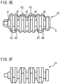
- FIGS. 3A to 3F are diagrams to show an exemplary production process of the present embodiment for forming a forged crankshaft.
- a crankshaft having the shape shown in FIG. 1 is produced.
- FIGS. 3A, 3B, 3C, 3D , 3E and 3F show a billet, an initial preform, an intermediate preform, a final preform, a finish-forged product, and a forged crankshaft (final product), respectively.
- a billet 22 is used as a workpiece, and the cross-sectional area thereof is reduced in regions to be formed into pins (hereinafter referred to as "pin-corresponding parts") and in regions to be formed into journals (hereinafter referred to as "journal-corresponding parts").
- pin-corresponding parts regions to be formed into pins
- journal-corresponding parts regions to be formed into journals
- a plurality of parts 23a with a smaller cross-sectional area are formed in the billet 22.
- an initial preform 23 as shown in FIG. 3B is obtained.
- reduce rolls or cross rolls may be used.
- the intermediate preform 24 includes rough journals 24j to be formed into journals J, rough pins 24p to be formed into pins P, primary rough arms (primary rough crankarms) 24a to be formed into arms A, a rough front part 24fr to be formed into a front part Fr, and a rough flange part 24fl to be formed into a flange part Fl.
- the process to form the intermediate preform 24 from the billet 22 is a preliminary forming process.
- the process shown in FIGS. 3B and 3C is an example, and it is possible to form an intermediate preform through another process. The details of the preliminary forming process will be described later.
- a forming process is performed.
- a final preform 25 is formed from the intermediate preform 24.
- the final preform 25 includes secondary rough arms (secondary rough crankarms) 25a of which shapes are more similar to the arms A than the shapes of the primary rough arms 24a are.
- the final preform 25 includes rough pins 25p, rough journals 25j, a rough front part 25fr, and a rough flange part 25fl. The details of the forming process will be described later.
- finish forging die forging is performed as in a conventional finish forging process.
- a finish-forged product 26 is formed from the final preform 25.
- the finish-forged product 26 includes a plurality of journals J, a plurality of pins P, and a plurality of arms A.
- FIG. 3E shows an example in which flash B is formed in the finish forging process. The details of the finish forging process will be described later.
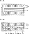
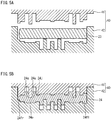
- FIGS. 4A to 5B are diagrams to show an exemplary preforming process.
- FIGS. 4A and 4B show a step of forming the initial preform 23 shown in FIG. 3B .
- FIGS. 5A and 5B show a step of forming the intermediate preform 24 shown in FIG. 3C .
- FIG. 4A shows the billet 22 having a circular cross section, and a vertical pair of pressing dies 30.
- the pressing dies 30 include an upper die 31 and a lower die 32.
- the upper die 31 and the lower die 32 have shapes that permit the billet 22 to be formed into the initial preform 23.
- the billet 22 is placed between the upper die 31 and the lower die 32.
- the upper die 31 is moved down to press the billet 22.
- the cross-sectional area of the billet 22 is decreased in the pin-corresponding parts and the journal-corresponding parts, so that the parts 23a with a smaller cross-sectional area are formed.
- the initial preform 23 is obtained.
- the cross sections of the pin-corresponding parts and the journal-corresponding parts are elliptical. The long axes of these ellipses extend in the direction perpendicular to the paper surface of FIG. 4B .
- the pressing dies 40 include an upper die 41 and a lower die 42.
- the upper die 41 and the lower die 42 have shapes that permit the initial preform 23 to be formed into the intermediate preform 24.
- the initial preform 23 is placed between the upper die 41 and the lower die 43.
- the initial preform 23 is placed such that the long axes of the elliptical cross sections of the pin-corresponding pars and the journal-corresponding parts are parallel to the vertical direction (pressing direction). Accordingly, the long axes of the elliptical cross sections of the pin-corresponding parts and the journal-corresponding parts are arranged in parallel to the vertical direction on the paper surface of FIG. 5A .
- the initial preform 23, which was formed by the pressing dies 30, is placed in the pressing dies 40 after being rotated by 90 degrees around its own axis.
- the intermediate preform 24 includes rough journals 24j to be formed into the journals J, rough pins 24p to be formed into the pins P, primary rough arms (primary rough crankarms) 24a to be formed into the arms A, a rough front part 24fr to be formed into the front part Fr, and a rough flange part 24fl to be formed into the flange part Fl (see FIG. 3C ).
- the rough pins 24p are slightly decentered with respect to the rough journals 24j in the decentering directions of the pins P.
- the length (the longitudinal dimension along the axis) of the intermediate preform 24 is greater than the length (the longitudinal dimension along the axis) of the final product, i.e., the forged crankshaft.
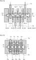
- FIGS. 6A to 6C , 7A and 7B are diagrams to show an exemplary forming process.
- FIG. 6A and 7A show the state before the start of the forming process
- FIG. 6B shows the state in the middle of the forming process.
- FIGS. 6C and 7B show the state at the completion of the forming process.
- FIGS. 6A and 6B are vertical longitudinal sectional views along the line VIA-VIA in FIG. 7A .
- FIGS. 6A and 6B show a vertical longitudinal section along a center line of the intermediate preform 24.
- FIG. 6C is a vertical longitudinal sectional view along the line VIC-VIC in FIG. 7B.
- FIG. 7A is a horizontal sectional view along the line VIIA-VIIA in FIG.
- FIG. 7B is a horizontal sectional view along the line VIIB-VIIB in FIG. 6C . More specifically, FIGS. 7A and 7B show a horizontal section at a level slightly lower than the die-parting plane of holding dies 60. To facilitate understanding, in FIGS. 6A to 6C , 7A and 7B , the outline of the intermediate preform 24 and the outline of the final preform 25 are shown by thick dotted line. In FIGS. 7A and 7B , further, the outline of a wedge receiver 72a, which will be described later, is partly shown by thin dotted line.
- the holding dies 60 include stationary holding dies 61, movable holding dies 62, front-side holding dies 63 and flange-side holding dies 64. The mechanism for moving these dies will be described later. These dies include upper dies and lower dies.
- the holding dies 60 include a plurality of pairs of holding dies, each pair composed of a lower holding die 60a and an upper holding die 60b.
- the pair of stationary holding dies 61 includes a lower stationary holding die 61a and an upper stationary holding die 61b.
- Each pair of movable holding dies 62 includes a lower movable holding die 62a and an upper movable holding die 62b.
- the pair of front-side holding dies 63 includes a lower front-side holding die 63a and an upper front-side holding die 63b.
- the pair of flange-side holding dies 64 includes a lower flange-side holding die 64a and an upper flange-side holding die 64b.
- Each pair of pin decentering dies 71 includes a lower pin decentering die 71a and an upper pin decentering die 71b.
- the lower dies are placed on a bolster base 102a, which will be described later.
- the upper dies are supported by a die cushion base 104, which will be described later, and the upper dies move vertically with a movement of the die cushion base 104.
- the holding dies 60 are to hold the rough journals 24j.
- the stationary holding dies 61 do not move in the axial direction of the intermediate preform 24.
- the movable dies 62, the front-side holding dies 63 and the flange-side holding dies 64 are movable in the axial direction of the intermediate preform 24.
- the pin decentering dies 71 are to decenter the rough pins 24p, and the pin decentering dies 71 are movable in directions perpendicular to the pressing direction by the holding dies 60 and the axial direction of the preform 24.
- the respective holding dies 60 and pin decentering dies 71 have recesses 60c and 71c to form spaces for forming and holding the primary rough arms (see FIG. 6A ).
- the intermediate preform 24 is placed on the lower dies.
- the intermediate preform 24 is placed such that the directions in which the rough pins 24p are to be decentered are perpendicular to the pressing direction by the holding dies 60 and the axial direction of the intermediate preform 24.
- the respective dies are arranged at intervals in the axial direction of the preform.
- the upper dies are moved down with a downward movement of the die cushion base 104, and the rough journals 24j are pressed vertically and held by the pairs of holding dies 60. As shown in FIG. 6B , the rough journals 24j are locked in the respective pairs of holding dies 60.
- the rough journal 24j held by the pair of stationary holding dies 61 is not horizontally movable.
- the pin decentering is performed by moving the pin decentering dies 71 in directions which are perpendicular to the pressing direction by the holding dies 60 (that is, in horizontal directions) and perpendicular to the axial direction of the intermediate preform 24.
- the moving direction of the two pairs of pin decentering dies 71 at both ends is opposite to the moving direction of the two pairs of pin decentering dies 71 in the center (see arrows in FIG. 7A ).
- the pin decentering dies 71a are pushed and moved by the wedge receiver 72a.
- the upper pin decentering dies 71b are pushed and moved by a wedge receiver 72b, which will be described later, in the same direction as the pin decentering dies 71a.
- FIG. 8A schematically shows a cross section of the pair of stationary holding dies 61 and the rough journal 24j therein in the state before the start of the forming process (in the state shown in FIGS. 6A and 7A ).
- FIG. 8B schematically shows a cross section of the pair of stationary holding dies 61 and the rough journal 25j therein in the state at the completion of the forming process (in the state shown in FIGS. 6C and 7B ).
- These figures are sectional views on a plane perpendicular to the axial direction of the preform, and in these figures, the pair of stationary holding dies 61 is shown only partly. In order to facilitate understanding, in FIGS.
- a rough journal center line JCT which is a vertical line passing the center of the rough journal 24j or 25j is shown.
- FIGS. 9A, 9B , 10A and 10B which will be described later, the rough journal center line JCT is shown.
- the positions of the rough journal center line JCT shown in FIGS. 9A to 10B are merely examples to facilitate understanding.
- FIG. 9A schematically shows a cross section of one of the rough pins 24p and the pair of pin decentering dies 71 therearound in the state before the start of the forming process (in the state shown in FIGS. 6A and 7A ).
- FIG. 9B schematically shows a cross section of the rough pin 25p and the pair of pin decentering dies 71 therearound in the state at the completion of the forming process (in the state shown in FIGS. 6C and 7B ).
- These figures are sectional views on a plane perpendicular to the axial direction of the intermediate preform.
- the rough pin 25p shown in FIG. 9B is decentered.
- each pair of pin decentering dies 71 has a space for the rough pins 24p.
- FIG. 10A schematically shows a cross section of the primary pair of stationary holding dies 61 and one of the rough arms 24a adjacent thereto in the state before the start of the forming process (in the state shown in FIGS. 6A and 7A ).
- FIG. 10B schematically shows a cross section of the pair of stationary holding dies 61 and the secondary rough arm 25a adjacent thereto in the state at the completion of the forming process (in the state shown in FIGS. 6C and 7B ).
- These figures are sectional views on a plane perpendicular to the axial direction of the intermediate preform 24, and these figures show a section at a space made in the stationary holding dies 61 for the rough arm, that is, a space made by recesses 60c. As shown in FIG.
- the pairs of holding dies 60 have spaces for the primary rough arms 24a.
- the secondary rough arms 25a which have shapes more similar to the shapes of the arms A than the shapes of the primary rough arms 24a, are formed.
- the cross-sectional areas of the secondary rough arms 25a are greater than the cross-sectional areas of the primary rough arms 24a.
- the axial pressing is performed by causing the pair of front-side holding dies 63 and the pair of flange-side holding dies 64 to come closer to each other.
- the pair of front-side holding dies 63 and the pair of flange-side holding dies 64 are moved in the axial direction of the preform 24.
- the forming process may be performed to form flash on the final preform 25.
- the direction of placement of the final preform 25 for the finish forging process is the same as the direction of placement of the intermediate preform 24 for the forming process, which includes the pin decentering.
- the preform 24 or 25 is placed such that the decentering directions of the rough pins 24p or 25p are in directions parallel to the horizontal direction.
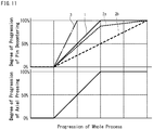
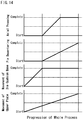
- the timing of performing the pin decentering and the axial pressing is described.
- the horizontal axis indicates progression (time course) of the whole process
- the vertical axis indicates degree of progression of each process.
- the degree of progression of the pin decentering means the rate of the actual movement distance of the rough pins when the final movement distance of the rough pins to be attained by the pin decentering is considered as 100%.
- the degree of progression of the axial pressing means the rate of the actual reduction of the intermediate preform in the axial dimension when the final reduction of the intermediate preform in the axial direction (the final decrease in the axial dimension of the intermediate preform) to be attained by the axial pressing is considered as 100%.
- the solid line 1 in FIG. 11 shows a case in which the axial pressing is completed at the same time as the completion of the pin decentering.
- the dotted lines 2a and 2b in FIG. 11 show cases in which the axial pressing is completed before the completion of the pin decentering.
- the dot-and-dash line 3 in FIG. 11 shows a case in which the axial pressing is completed after the completion of the pin decentering.
- the movements of the pin decentering dies may apply force to open the holding dies. Accordingly, there is a risk that the material may flow out along the journal die parting surfaces and the like. In the conventional production method, therefore, in order to reduce the risk of the flow-out of the material, it is important to complete the axial pressing before the completion of the pin decentering.
- the moving directions of the pin decentering dies 71 are parallel to the horizontal direction, and are perpendicular to the pressing direction by the holding dies 60 (vertical direction) and the axial direction of the intermediate preform 24.
- the movements of the pin decentering dies are unlikely to apply force to open the holding dies, and the risk of flow-out of the material along the journal die parting surfaces and the like is low.
- the production method according to the present invention therefore, even when the axial pressing is completed at the same time as the completion of the pin decentering or after the completion of the pin decentering, a high risk of flow-out of the material can be avoided.
- the production method according to the present embodiment is not absolutely to exclude completing the axial pressing before the completion of the pin decentering.
- the pin decentering is completed before the completion of the axial pressing, the flow of the material of the intermediate preform 24 during the pin decentering is less suppressed.
- the final preform 25 obtained in that case is unlikely to have a material deficiency in the pin shoulders of the rough pins 25p (see FIG. 3D ), and the final preform 25 is likely to have accurate shapes in the portions around the rough pins 25p.
- the portions around the pin shoulders of the final preform have shapes more similar to the shapes of those portions of the finish-forged product, and the final preform can be set more steadily in the dies for finish forging.
- FIGS. 12A and 13A schematically show an exemplary forming apparatus 100 which is used for the forming process.
- the parts of the apparatus which are not relevant to the description below are not drawn or drawn only simply, and the apparatus is not hatched.
- FIG. 12A shows a vertical longitudinal section along the axis of the intermediate preform 24.
- FIG. 13A shows a vertical cross section perpendicular to the axis of the intermediate preform 24 at a portion where a pair of pin decentering dies 71 is located.
- FIGS. 12A and 13A show a state before the start of the forming process.
- the forming apparatus 100 includes a plate (forming apparatus body) 101, a bolster base 102, die cushion cylinders (extension and contraction mechanism) 103, a die cushion base 104, hydraulic cylinders (horizontal cylinders) 105, and pin decentering wedges 106.
- the plate 101 includes a lower plate 101a and an upper plate 101b.
- the bolster base 102 includes a lower bolster base 102a and an upper bolster base 102b (base).
- the bolster base 102 is supported by the plate 101.
- the die cushion base 104 is supported by the bolster base 102b via the die cushion cylinders 103.
- the die cushion cylinders 103 are cylinders which are not contracted merely by the load required for pressing and holding of the rough journals but are contracted by the whole load from the plate 101.
- the hydraulic cylinders 105 are cylinders to press the intermediate preform 24 in the axial direction.
- the forming apparatus 100 shown in FIG. 12A has two such hydraulic cylinders 105, and specifically, one by the side of the rough front part 24fr and one by the side of the rough flange part 24fl. Both ends of the intermediate preform 24 are pressed by these two hydraulic cylinders 105, and thereby, the intermediate preform 24 is pressed in the axial direction.
- the lower holding dies 60a and the lower pin decentering dies 71a are arranged on the bolster base 102a.
- the upper holding dies 60b and the upper pin decentering dies 71b are supported by the die cushion base 104.
- these upper dies are suspended by fasteners (L-shaped fasteners) projecting from the die cushion base 104.
- the pairs of holding dies 60, the pairs of movable dies 62, the pair of front-side holding dies 63 and the pair of flange-side holding dies 64 are movable in the axial direction of the preform.
- the pin decentering wedges 106 penetrate through the die cushion base 104, and the wedges 106 are movable independently from the die cushion base 104.
- Each of the wedges 106 has an inclined surface.
- the wedges 106 are fixed on the bolster base 102b.
- the plate 101b is a plate to push the holding dies 60b via the die cushion cylinders (expansion and contraction mechanism) 103.
- each of the pin decentering dies 71a is connected with a wedge receiver 72a. More specifically, an end of each pin decentering die 71a is connected with the wedge receiver 72a such that the pin decentering die 71a is movable in the axial direction of the intermediate preform 24 relative to the wedge receiver 72a (see FIGS. 7A and 7B ). As shown in FIG. 13A , the wedge receiver 72a has an inclined surface facing the inclined surface of the wedge 106. Similarly, an end of each of the pin decentering dies 71b is connected with a wedge receiver 72b.
- each pin decentering die 71b is connected with the wedge receiver 72b such that the pin decentering die 71b is movable in the axial direction of the intermediate preform 24 relative to the wedge receiver 72b.
- the wedge receiver 72b has an inclined surface facing the inclined surface of the wedge 106.
- the wedge receivers 72a and 72b are movable only in the pin decentering directions.
- the pin decentering dies 71a are movable in the axial direction of the intermediate preform as well as in the pin decentering directions.
- the pin decentering dies 71b are movable in the axial direction of the intermediate preform as well as in the pin decentering directions. Since the pin decentering dies 71 are movable in the axial direction of the intermediate preform, the wedge receiver 72a (and the wedge receiver 72b), as shown in FIG. 7A , has a shape extending in the axial direction of the intermediate preform.
- the intermediate preform 24 is placed between the lower dies and the upper dies.
- the intermediate preform 24 is placed such that the decentering directions in which the rough pins 24p are to be decentered are parallel to the horizontal direction. This placement facilitates even mass distribution in the horizontal direction and thereby permits mass balance in the horizontal direction. This results in steady positioning of the intermediate preform 24, which reduces the risk of faulty forming during the forming process.
- the plate 101 is moved down to hold the rough journals 24j and to perform the pin decentering.
- the hydraulic cylinders 105 are driven to perform the axial pressing.
- FIGS. 12B and 13B are sectional views at the same portion shown in FIGS. 12A and 13A .
- the die cushion cylinders 103 are contracted.
- the die cushion cylinders 103 are cylinders which are contracted by the load from the plate 101b. Since the die cushion cylinders 103 are contractable, it is possible to move down the pin decentering wedges 106 continuously without changing the position of the die cushion base 104.
- the two hydraulic cylinders 105 push the pair of front-side holding dies 63 and the pair of flange-side holding dies 64, respectively, so as to cause the pair of dies 63 and the pair of dies 64 to come closer to each other.
- the pairs of movable holding dies 62 and the pairs of pin decentering dies 71 are moved in the axial direction of the intermediate preform to come closer to the pair of stationary holding dies 61 at the center.
- the pin decentering dies 71 are moved in both the pressing direction by the holding dies 60 and the pin decentering directions that are perpendicular to the pressing direction by the holding dies 60 and the axial direction of the intermediate preform.
- FIGS. 12C and 13C are sectional views at the same portion shown in FIGS. 12A and 13A .
- each of the dies (dies composing the holding dies 60 and the pin decentering dies 71) is in contact with the die(s) adjacent thereto in the axial direction of the final preform 25.
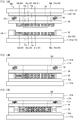
- FIG. 14 is a diagram showing exemplary timing of the movement of the upper plate 101b, the movement of the die cushion base 104, the pin decentering, and the axial pressing.
- the horizontal axis indicates progression (time course) of the whole process.
- FIG. 14 shows a case in which the pin decentering and the axial pressing are started at the same time and in which the axial pressing is completed before the completion of the pin decentering.
- the timing of the start and completion of the pin decentering is adjustable by changing the shapes of the wedges 106 and the wedge receivers 72a and 72b, and the like.
- the pin decentering dies 71 may be moved by hydraulic cylinders or other actuators.
- the final preform 25 (see FIG. 3D ) is formed.
- the shapes of the rough journals 25j, the rough pins 25p and the secondary rough arms 25a of the final preform 25 are more similar to the shapes of the journals J, the pins P and the arms A of the final product than the shapes of those parts of the intermediate preform 24 are.
- the final preform 25 is pressed by a pair of pressing dies in a direction perpendicular to the decentering directions of the rough pins 25p and the axial direction of the final preform 25.
- a finish-forged product 26 (see FIG. 3E ) including a plurality of journals J, a plurality of pins P, and a plurality of crankarms A is formed.
- the finish forging process can be performed by a conventional apparatus. In this case, conventional pressing dies can be used.
- the direction of placement of the final preform 25 for the finish forging process is the same as the direction of placement of the intermediate preform 24 and the final preform 25 during the forming process.
- the intermediate preform or the final preform is subjected to the process while the preform is placed such that the decentering directions of the rough pins are parallel to the horizontal direction. Therefore, even when flash is formed along the die parting surfaces of the holding dies in the forming process, it is possible to reduce the risk that the flash may cause seams in the die forging process.
- the present invention is applicable to production of a forged crankshaft.
Applications Claiming Priority (2)
| Application Number | Priority Date | Filing Date | Title |
|---|---|---|---|
| JP2016231013 | 2016-11-29 | ||
| PCT/JP2017/030238 WO2018100810A1 (ja) | 2016-11-29 | 2017-08-24 | 鍛造クランク軸の製造方法 |
Publications (1)
| Publication Number | Publication Date |
|---|---|
| EP3549691A1 true EP3549691A1 (en) | 2019-10-09 |
Family
ID=62241556
Family Applications (1)
| Application Number | Title | Priority Date | Filing Date |
|---|---|---|---|
| EP17876386.8A Withdrawn EP3549691A1 (en) | 2016-11-29 | 2017-08-24 | Production method for forged crankshaft |
Country Status (7)
| Country | Link |
|---|---|
| US (1) | US10799940B2 (zh) |
| EP (1) | EP3549691A1 (zh) |
| JP (1) | JP6658916B2 (zh) |
| CN (1) | CN109982784B (zh) |
| BR (1) | BR112019005745A2 (zh) |
| MX (1) | MX2019005016A (zh) |
| WO (1) | WO2018100810A1 (zh) |
Families Citing this family (1)
| Publication number | Priority date | Publication date | Assignee | Title |
|---|---|---|---|---|
| CN109622856B (zh) * | 2018-12-13 | 2020-06-05 | 中国兵器工业第五九研究所 | 一种全纤维曲轴镦挤成形过程组合模具轴向间距调整方法 |
Family Cites Families (9)
| Publication number | Priority date | Publication date | Assignee | Title |
|---|---|---|---|---|
| JP2000094087A (ja) | 1998-09-16 | 2000-04-04 | Sumitomo Metal Ind Ltd | クランク軸の製造技術 |
| DE102006024715B4 (de) * | 2006-05-26 | 2008-07-24 | Niles-Simmons Industrieanlagen Gmbh | Verfahren zum Bearbeiten der Lagersitze der Haupt- und Hublager von Kurbelwellen sowie Werkzeugmaschine zur Durchführung des Verfahrens |
| JP2011078995A (ja) * | 2009-10-05 | 2011-04-21 | Toyota Motor Corp | クランクシャフト粗形材の成形方法及び成形装置 |
| JP2012161819A (ja) * | 2011-02-08 | 2012-08-30 | Toyota Motor Corp | クランクシャフトの製造装置、クランクシャフトの製造方法、およびクランクシャフト |
| WO2014016875A1 (ja) * | 2012-07-27 | 2014-01-30 | 新日鐵住金株式会社 | 型鍛造クランク軸の製造方法 |
| CN104602842B (zh) * | 2012-09-07 | 2016-06-08 | 新日铁住金株式会社 | 锻造曲轴的精锻用坯料的成形装置 |
| JP5862800B2 (ja) * | 2012-12-12 | 2016-02-16 | 新日鐵住金株式会社 | 鍛造クランク軸 |
| MX2016011094A (es) * | 2014-02-27 | 2017-02-20 | Nippon Steel & Sumitomo Metal Corp | Aparato para formar una pieza en blanco para acabado por forja para un cigüeñal forjado para un motor de tres cilindros y metodo de fabricacion de un cigüeñal forjado para un motor de tres cilindros utilizando la misma. |
| WO2016152933A1 (ja) * | 2015-03-24 | 2016-09-29 | 新日鐵住金株式会社 | 鍛造クランク軸の製造方法 |
-
2017
- 2017-08-24 JP JP2018553658A patent/JP6658916B2/ja active Active
- 2017-08-24 US US16/332,463 patent/US10799940B2/en active Active
- 2017-08-24 WO PCT/JP2017/030238 patent/WO2018100810A1/ja unknown
- 2017-08-24 CN CN201780071751.4A patent/CN109982784B/zh active Active
- 2017-08-24 BR BR112019005745A patent/BR112019005745A2/pt not_active IP Right Cessation
- 2017-08-24 EP EP17876386.8A patent/EP3549691A1/en not_active Withdrawn
- 2017-08-24 MX MX2019005016A patent/MX2019005016A/es unknown
Also Published As
| Publication number | Publication date |
|---|---|
| BR112019005745A2 (pt) | 2019-06-18 |
| CN109982784A (zh) | 2019-07-05 |
| US20200290112A1 (en) | 2020-09-17 |
| JP6658916B2 (ja) | 2020-03-04 |
| CN109982784B (zh) | 2020-10-13 |
| WO2018100810A1 (ja) | 2018-06-07 |
| US10799940B2 (en) | 2020-10-13 |
| MX2019005016A (es) | 2019-06-20 |
| JPWO2018100810A1 (ja) | 2019-07-18 |
Similar Documents
| Publication | Publication Date | Title |
|---|---|---|
| US9707618B2 (en) | Apparatus for forming a blank for finish forging for a forged crankshaft for a three-cylinder engine and method for manufacturing a forged crankshaft for a three-cylinder engine using the same | |
| US9630239B2 (en) | Apparatus for forming a blank for finish forging for a forged crankshaft | |
| EP3275568B1 (en) | Method for producing forged crankshaft | |
| US10124398B2 (en) | Method for producing a forged crankshaft | |
| US10029297B2 (en) | Apparatus for forming a blank for finish forging for a forged crankshaft for a three-cylinder engine and method for manufacturing a forged crankshaft for a three-cylinder engine using the same | |
| EP3170576B1 (en) | Method for producing a forged crankshaft | |
| EP3278903B1 (en) | Method for producing forged crankshaft | |
| EP3517230A1 (en) | Method for manufacturing forged crankshaft | |
| EP3299096B1 (en) | Apparatus and method for manufacturing forged crankshaft | |
| EP3520925A1 (en) | Manufacturing method for forged crankshaft | |
| US10799940B2 (en) | Method for producing forged crankshaft | |
| US10441995B2 (en) | Method for producing forged crankshaft | |
| US11253910B2 (en) | Method for producing forged crankshaft | |
| US11045865B2 (en) | Method for producing forged crankshaft | |
| US10828693B2 (en) | Apparatus for manufacturing forged crankshaft | |
| US10005122B2 (en) | Apparatus for forming a blank for finish forging for a forged crankshaft for a straight-6-cylinder engine and method for manufacturing a forged crankshaft for a straight-6-cylinder engine using the same |
Legal Events
| Date | Code | Title | Description |
|---|---|---|---|
| PUAI | Public reference made under article 153(3) epc to a published international application that has entered the european phase |
Free format text: ORIGINAL CODE: 0009012 |
|
| 17P | Request for examination filed |
Effective date: 20190625 |
|
| AK | Designated contracting states |
Kind code of ref document: A1 Designated state(s): AL AT BE BG CH CY CZ DE DK EE ES FI FR GB GR HR HU IE IS IT LI LT LU LV MC MK MT NL NO PL PT RO RS SE SI SK SM TR |
|
| AX | Request for extension of the european patent |
Extension state: BA ME |
|
| DAV | Request for validation of the european patent (deleted) | ||
| DAX | Request for extension of the european patent (deleted) | ||
| STAA | Information on the status of an ep patent application or granted ep patent |
Free format text: STATUS: THE APPLICATION HAS BEEN WITHDRAWN |
|
| 18W | Application withdrawn |
Effective date: 20200515 |