EP3549242B1 - Electric machine provided with an enclosed cooling assembly paired to an open cooling assembly - Google Patents
Electric machine provided with an enclosed cooling assembly paired to an open cooling assembly Download PDFInfo
- Publication number
- EP3549242B1 EP3549242B1 EP17875968.4A EP17875968A EP3549242B1 EP 3549242 B1 EP3549242 B1 EP 3549242B1 EP 17875968 A EP17875968 A EP 17875968A EP 3549242 B1 EP3549242 B1 EP 3549242B1
- Authority
- EP
- European Patent Office
- Prior art keywords
- cooling
- cooling fluid
- electric machine
- recited
- wall
- Prior art date
- Legal status (The legal status is an assumption and is not a legal conclusion. Google has not performed a legal analysis and makes no representation as to the accuracy of the status listed.)
- Active
Links
Images




Classifications
-
- B—PERFORMING OPERATIONS; TRANSPORTING
- B60—VEHICLES IN GENERAL
- B60K—ARRANGEMENT OR MOUNTING OF PROPULSION UNITS OR OF TRANSMISSIONS IN VEHICLES; ARRANGEMENT OR MOUNTING OF PLURAL DIVERSE PRIME-MOVERS IN VEHICLES; AUXILIARY DRIVES FOR VEHICLES; INSTRUMENTATION OR DASHBOARDS FOR VEHICLES; ARRANGEMENTS IN CONNECTION WITH COOLING, AIR INTAKE, GAS EXHAUST OR FUEL SUPPLY OF PROPULSION UNITS IN VEHICLES
- B60K11/00—Arrangement in connection with cooling of propulsion units
- B60K11/02—Arrangement in connection with cooling of propulsion units with liquid cooling
-
- H—ELECTRICITY
- H02—GENERATION; CONVERSION OR DISTRIBUTION OF ELECTRIC POWER
- H02K—DYNAMO-ELECTRIC MACHINES
- H02K5/00—Casings; Enclosures; Supports
- H02K5/04—Casings or enclosures characterised by the shape, form or construction thereof
-
- B—PERFORMING OPERATIONS; TRANSPORTING
- B60—VEHICLES IN GENERAL
- B60K—ARRANGEMENT OR MOUNTING OF PROPULSION UNITS OR OF TRANSMISSIONS IN VEHICLES; ARRANGEMENT OR MOUNTING OF PLURAL DIVERSE PRIME-MOVERS IN VEHICLES; AUXILIARY DRIVES FOR VEHICLES; INSTRUMENTATION OR DASHBOARDS FOR VEHICLES; ARRANGEMENTS IN CONNECTION WITH COOLING, AIR INTAKE, GAS EXHAUST OR FUEL SUPPLY OF PROPULSION UNITS IN VEHICLES
- B60K1/00—Arrangement or mounting of electrical propulsion units
-
- F—MECHANICAL ENGINEERING; LIGHTING; HEATING; WEAPONS; BLASTING
- F04—POSITIVE - DISPLACEMENT MACHINES FOR LIQUIDS; PUMPS FOR LIQUIDS OR ELASTIC FLUIDS
- F04C—ROTARY-PISTON, OR OSCILLATING-PISTON, POSITIVE-DISPLACEMENT MACHINES FOR LIQUIDS; ROTARY-PISTON, OR OSCILLATING-PISTON, POSITIVE-DISPLACEMENT PUMPS
- F04C2/00—Rotary-piston machines or pumps
- F04C2/08—Rotary-piston machines or pumps of intermeshing-engagement type, i.e. with engagement of co-operating members similar to that of toothed gearing
- F04C2/10—Rotary-piston machines or pumps of intermeshing-engagement type, i.e. with engagement of co-operating members similar to that of toothed gearing of internal-axis type with the outer member having more teeth or tooth-equivalents, e.g. rollers, than the inner member
- F04C2/102—Rotary-piston machines or pumps of intermeshing-engagement type, i.e. with engagement of co-operating members similar to that of toothed gearing of internal-axis type with the outer member having more teeth or tooth-equivalents, e.g. rollers, than the inner member the two members rotating simultaneously around their respective axes
-
- H—ELECTRICITY
- H02—GENERATION; CONVERSION OR DISTRIBUTION OF ELECTRIC POWER
- H02K—DYNAMO-ELECTRIC MACHINES
- H02K1/00—Details of the magnetic circuit
- H02K1/06—Details of the magnetic circuit characterised by the shape, form or construction
- H02K1/22—Rotating parts of the magnetic circuit
-
- H—ELECTRICITY
- H02—GENERATION; CONVERSION OR DISTRIBUTION OF ELECTRIC POWER
- H02K—DYNAMO-ELECTRIC MACHINES
- H02K5/00—Casings; Enclosures; Supports
- H02K5/04—Casings or enclosures characterised by the shape, form or construction thereof
- H02K5/10—Casings or enclosures characterised by the shape, form or construction thereof with arrangements for protection from ingress, e.g. water or fingers
-
- H—ELECTRICITY
- H02—GENERATION; CONVERSION OR DISTRIBUTION OF ELECTRIC POWER
- H02K—DYNAMO-ELECTRIC MACHINES
- H02K5/00—Casings; Enclosures; Supports
- H02K5/04—Casings or enclosures characterised by the shape, form or construction thereof
- H02K5/20—Casings or enclosures characterised by the shape, form or construction thereof with channels or ducts for flow of cooling medium
- H02K5/203—Casings or enclosures characterised by the shape, form or construction thereof with channels or ducts for flow of cooling medium specially adapted for liquids, e.g. cooling jackets
-
- H—ELECTRICITY
- H02—GENERATION; CONVERSION OR DISTRIBUTION OF ELECTRIC POWER
- H02K—DYNAMO-ELECTRIC MACHINES
- H02K9/00—Arrangements for cooling or ventilating
- H02K9/19—Arrangements for cooling or ventilating for machines with closed casing and closed-circuit cooling using a liquid cooling medium, e.g. oil
-
- H—ELECTRICITY
- H02—GENERATION; CONVERSION OR DISTRIBUTION OF ELECTRIC POWER
- H02K—DYNAMO-ELECTRIC MACHINES
- H02K9/00—Arrangements for cooling or ventilating
- H02K9/19—Arrangements for cooling or ventilating for machines with closed casing and closed-circuit cooling using a liquid cooling medium, e.g. oil
- H02K9/193—Arrangements for cooling or ventilating for machines with closed casing and closed-circuit cooling using a liquid cooling medium, e.g. oil with provision for replenishing the cooling medium; with means for preventing leakage of the cooling medium
-
- H—ELECTRICITY
- H02—GENERATION; CONVERSION OR DISTRIBUTION OF ELECTRIC POWER
- H02K—DYNAMO-ELECTRIC MACHINES
- H02K9/00—Arrangements for cooling or ventilating
- H02K9/24—Protection against failure of cooling arrangements, e.g. due to loss of cooling medium or due to interruption of the circulation of cooling medium
-
- B—PERFORMING OPERATIONS; TRANSPORTING
- B60—VEHICLES IN GENERAL
- B60K—ARRANGEMENT OR MOUNTING OF PROPULSION UNITS OR OF TRANSMISSIONS IN VEHICLES; ARRANGEMENT OR MOUNTING OF PLURAL DIVERSE PRIME-MOVERS IN VEHICLES; AUXILIARY DRIVES FOR VEHICLES; INSTRUMENTATION OR DASHBOARDS FOR VEHICLES; ARRANGEMENTS IN CONNECTION WITH COOLING, AIR INTAKE, GAS EXHAUST OR FUEL SUPPLY OF PROPULSION UNITS IN VEHICLES
- B60K1/00—Arrangement or mounting of electrical propulsion units
- B60K2001/003—Arrangement or mounting of electrical propulsion units with means for cooling the electrical propulsion units
- B60K2001/006—Arrangement or mounting of electrical propulsion units with means for cooling the electrical propulsion units the electric motors
-
- B—PERFORMING OPERATIONS; TRANSPORTING
- B60—VEHICLES IN GENERAL
- B60Y—INDEXING SCHEME RELATING TO ASPECTS CROSS-CUTTING VEHICLE TECHNOLOGY
- B60Y2200/00—Type of vehicle
- B60Y2200/90—Vehicles comprising electric prime movers
- B60Y2200/92—Hybrid vehicles
-
- F—MECHANICAL ENGINEERING; LIGHTING; HEATING; WEAPONS; BLASTING
- F01—MACHINES OR ENGINES IN GENERAL; ENGINE PLANTS IN GENERAL; STEAM ENGINES
- F01P—COOLING OF MACHINES OR ENGINES IN GENERAL; COOLING OF INTERNAL-COMBUSTION ENGINES
- F01P2050/00—Applications
- F01P2050/24—Hybrid vehicles
Definitions
- the present disclosure relates to electric machines. More specifically, the present disclosure is concerned with an electric machine provided with an enclosed cooling assembly paired to an open cooling assembly.
- Electric machines, motors or generators are well known in the art. It is also widely known that electric machines generate heat as a byproduct and that this heat must be somehow extracted from the machine to improve the performance of the machine and/or prevent early degradation or failure thereof.
- Electric machines are often air-cooled. This is generally done by providing apertures in the body of the machine to force air therethrough. The efficiency of such a cooling arrangement is mostly poor since air is an usually low efficiency cooling fluid. Furthermore, some electric machines operate in environments that are such that it is not possible to provide apertures to allow air therein. Accordingly, liquid cooling arrangements for electric machines have been designed.
- Patent Literature EP2372881A2 describes a permanent magnet rotating electric machine which can efficiently reduce a temperature rise in the rotating machine without enlarging a heat exchanger and water-cooling unit.
- the permanent magnet rotating electric machine comprising a stator with a stator coil wound on a stator iron core, a rotor with a plurality of permanent magnets disposed in the circumferential direction in a rotor iron core, which is disposed opposite to the stator iron core of the stator with a predetermined spacing there between and is fixed to a shaft, a water-cooling unit disposed around the outer circumference of the stator iron core, and a fan fixed to the shaft on the same side as at least one axial end of the rotor iron core to circulate cooling air in the permanent magnet rotating electric machine; further comprising ventilation paths, through which the cooling air flows, formed around the outer circumference of the water-cooling unit; wherein after the cooling air has been circulated by the fan in the machine for cooling, the cooling air is led to the ventilation paths
- US2011011203A1 describes an in-wheel motor drive device including a motor part, a reducer part, a wheel hub, and a reducer part lubricating mechanism to supply a lubricant oil to the reducer part.
- the reducer part lubricating mechanism includes a lubricant oil path, a lubricant oil supply port, a lubricant oil discharge port, a circulation oil path passing through a casing to connect the lubricant oil discharge port to the lubricant oil path, and to return the lubricant oil discharged from the lubricant oil discharge port to the lubricant oil path, a cooling water path provided in the casing so as to be in contact with the circulation oil path to cool down the lubricant oil passing through the circulation oil path, and a partition member arranged in a contact position between the circulation oil path and the cooling water path, to separate them.
- JP2007325436A relates to a full-close type liquid-cooled electric motor capable of improving a cooling effect of a rotor.
- the full-close type liquid-cooled electric motor is provided with an internal frame arranged to cover the circumferential periphery of an external frame and forming a cooling liquid flowing path between itself and the external frame.
- a first internal space and a second internal space are formed between a front lid and the rotor and between a rear lid and the rotor, ventilating holes (ventilating hole and external frame ventilating path) for making first and second internal spaces with each other are formed on the external frame and the rotor, and a fan for circulating air between the first and second internal spaces through the ventilating holes, the outer frame ventilation path is provided at the end of the rotor.
- DE102014216693A1 describes an electric drive machine for a motor vehicle, with a rotor shaft which is rotatable about a drive axis, a rotor which is non-rotatably connected to the rotor shaft and has at least one axial channel, a flow device which has an impeller non-rotatably connected to the rotor shaft for generating a flow circuit for a cooling medium, a housing comprising a housing wall and a housing channel which extends from the inside of the housing through the housing wall back into the inside of the housing, as well as a stator fixed to the housing, which surrounds the rotor in the circumferential direction, wherein the rotor, the stator, the flow device and a cooling medium are accommodated in the inside of the housing, wherein the flow circuit for the cooling medium comprises the axial channel in the rotor and the housing channel, and wherein a blocking unit is provided, which can selectively open or at least partially close a flow cross-section of the axial channel.
- the words “comprising” (and any form of comprising, such as “comprise” and “comprises”), “having” (and any form of having, such as “have” and “has”), "including” (and any form of including, such as “include” and “includes”) or “containing” (and any form of containing, such as “contain” and “contains”), are inclusive or open-ended and do not exclude additional, unrecited elements or process steps.
- axial direction refers to the direction of the rotation axis of the rotor, the direction of the central axis of the cylindrical stator, and the directions corresponding to them
- radial direction refers to the directions perpendicular to such axial directions
- circumumferential direction refers to each direction along the circumference of a circle drawn about a given point of the rotation axis on a plane perpendicular to the rotation axis.
- connection should be construed herein and in the appended claims broadly so as to include any cooperative or passive association between mechanical parts or components.
- such parts may be assembled together by direct coupling, or indirectly coupled using further parts.
- the coupling can also be remote, using for example a magnetic field or else.
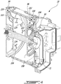
- Figure 1 is a perspective view of an electric machine 20 provided with an enclosed cooling assembly paired to an open cooling assembly.
- the electric machine 20 includes a central rotor 22 mounted to a shaft 24, a stator 26 provided with coils 28 (only the heads 30 of the coils are shown) and a casing 32 including a front plate 34, a back plate assembly 36 and a wall assembly including an outer wall 38, an intermediate wall 40 and an inner wall 42.
- An internal compartment of the casing 32 is generally defined by the front and back plates 34, 36 and by the inner wall 42.
- front plate 34 and the intermediate wall 40 are integral and the inner wall 42 is part of the back plate assembly 36.
- the shaft 24 is mounted to the front plate 34 via a bearing 44 and to the back plate assembly 36 via a bearing 46.
- the open cooling assembly includes an inlet 50, an outlet 52 and a cooling path 54 provided between the inner wall 42 and the intermediate wall 40.
- the back assembly 36 includes channels 60 and 62 respectively linking the inlet 50 and the outlet 52 to the cooling path 54.
- inner wall 42 includes projections 64 facing the intermediate wall 40 and defining the path of the flow of cooling fluid (see arrow 66).
- the projections 64 define a double-helix configuration of the cooling path of the cooling fluid.
- the projections 64 define a double-helix configuration of the cooling path of the cooling fluid.
- one skilled in the art would be in a position to design other projection topologies to generate a desired cooling path.
- seals in the form of O-rings are provided between the inner wall 42 and the intermediate wall 40.
- the cooling fluid flowing in the open cooling assembly is pumped by an external source (not shown) and is cooled by an external mechanism (also not shown), for example the conventional pump and radiator of a vehicle.
- This cooling fluid may be, for example a water ethylene glycol mixture.
- the enclosed cooling fluid is contained in the machine 20 and is cooled by the proximity of the open cooling fluid of the open cooling assembly as will be explained hereinbelow.
- the enclosed circuit cooling assembly includes a pump used to pump the enclosed circuit cooling fluid through a fluid cooling path where the enclosed circuit cooling fluid is cooled by being in the proximity of the cooling fluid of the open cooling assembly.
- the cooled enclosed circuit cooling fluid then enters the internal compartment of the casing 32 where it contacts the rotor 22 and the stator 26, therefore drawing heat therefrom, before entering a bottom reservoir where it is ready to be pumped again.
- the enclosed cooling assembly includes a gerotor pump 70 ( Figure 6 ) provided in the back plate assembly 36. Since gerotor pumps are believed well known in the art, pump 70 will not be described in details herein. Suffice to say that the back plate assembly 36 includes a central inlet channel 72 for the pump 70 and two lateral outlet channels 74 and 76 (see Figure 6 ). The channels are enclosed by a cover 78 sealed to the assembly 36 via a gasket 80 ( Figure 7 ) provided in a groove 82 ( Figure 5 ).
- the inlet channel 72 allows cooling fluid to be pumped from a bottom reservoir as will be described hereinbelow.
- a filter 84 is provided in the inlet channel 72 to filter particles that may be present in the cooling fluid of the enclosed circuit cooling assembly.
- Figure 6 also illustrates an inlet 86 and an outlet 88, closable by fasteners 90, used to fill and empty the cooling fluid when required.
- the back plate assembly 36 includes a relief valve system 91 provided with apertures 93 in communication with the lateral outlet channels 74 and 76 and a pressure-relief mechanism 95 that opens if the pressure in the outlet channels is greater than a predetermined threshold. Accordingly, if the cooling fluid of the enclosed cooling assembly is cold and thick, causing the pressure to increase, the mechanism 95 opens and the cooling fluid is introduced in the casing, preventing damage to the cooling circuit, for example. Similarly, if the pump is rotating at high speed, the pressure may sufficiently increase as to cause the relief mechanism 95 to open.
- the enclosed circuit cooling assembly includes two cooling paths both provided between the intermediate wall 40 and the outer wall 38.
- a first cooling path of the enclosed cooling assembly includes an inlet 92 ( Figure 5 ), associated with the outlet channel 74, and an outlet 94.
- the first cooling path is defined by projections 96 provided on the intermediate wall 40, facing the outer wall 38 (removed from Figure 5 for clarity).
- Small apertures 102 are provided close to the outlet 94. These apertures 102 allow a portion of the enclosed circuit cooling fluid to reach the top stator coils head 30 outer side (see arrow 213 in Figure 2 ), while the rest of the flow exits through outlet 94 to cool all of the coils head 30 inner side trough rotor centrifugal projection, as will be described hereinbelow.
- the second cooling path of the enclosed cooling assembly includes an inlet 98 ( Figure 7 ), associated with the outlet channel 76, and an outlet 100 ( Figure 4 ). Again, the second cooling path is defined by projections 96 provided on the intermediate wall 40, facing the outer wall 38 ( Figure 2 ).
- seals in the form of O-rings are provided between the outer wall 38 and the intermediate wall 40.
- the cooling fluid of the enclosed circuit cooling assembly is cooled by the prolonged contact with the intermediate wall 40. Furthermore, the cooling fluid of the enclosed circuit cooling assembly is also cooled by the contact with the outer wall 38, itself in contact with the ambient air.
- the external surface of the casing could be provided with fins (not shown) to improve the convection cooling of the cooling fluid of the enclosed circuit cooling assembly.
- the enclosed circuit cooling assembly includes slides 103 and 104 respectively located under outlets 94 and 100. These slides guide the cooled cooling fluid onto the end plates 106 and 108 of the rotor 22. It is to be noted that the other elements forming the rotor 22 are omitted from Figure 4 .
- the general idea is to distribute the cooled cooling fluid onto the heads 30, provided at both ends of the stator coils 28. Since the cooling fluid only enters the inside of the internal compartment of the casing 32 from the two outlets 94 and 100, the end plates 106 and 108 are configured to distribute the cooled cooling fluid outwardly towards the heads 30.
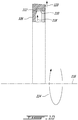
- Figure 10 which is a sectional view taken from Figure 9 , illustrates a peripheral generally U-shaped channel 110 designed to be filled with cooled cooling fluid 112 when the electric machine 20 is in operation, i.e. when the rotor 22 and thus the end plates 106 and 108 rotate (see arrow 114) about axis 116. Indeed, the forces acting on the cooled cooling fluid 112 upon rotation of the end plate 106 forces it in the channel 110 (see arrow 118). When the channel 110 is filled, it overflows outwardly and cooled cooling fluid is substantially evenly distributed onto the inner sides of the coil heads 30 (see arrows 120 in both figures 9 and 10 ).
- the T-shaped channels 122 provided on the inner surfaces of the end plates 106 and 108 are intended to allow trapped cooling fluid to egress the rotor 22. Indeed, cooling fluid could enter the laminations (schematically illustrated as 109 in Figures 7 and 8 ) forming the rotor 22 and become trapped therein.
- the end plates 106 and 108 also include apertures 124 allowing the rotor to be assembled using bolts passing through the end plates and the laminations.
- the slide 103 includes an aperture 126 allowing some of the cooled cooling fluid to reach the bearing 44 (see arrow 128).
- the bracket 130 mounting the bearing 44 to the front plate 34 includes a funnel portion 132 creating a small gap through which cooled cooling fluid can reach the bearing 44 to cool and lubricate the bearing.
- oil seeping from the pump 70 through interstices between the pump and the back wall assembly 36 supplies enough cooling fluid for lubrication and cooling of this bearing 46.
- Figure 2 also shows that a deflector 105 is provided between the outlet 100 and the slide 104. Apertures 107 of this deflector allow a portion of the cooled cooling fluid to drip directly on the heads 30 of the coils 28 (see arrow 109) before returning on the slide 106.
- the now warmed cooling fluid After cooling the heads 30 of the coils 28 and the other elements of the electric machine 20, the now warmed cooling fluid, thanks to gravity, reaches the bottom of the internal compartment of the casing 32 and may enter a bottom reservoir 134 through apertures 136 and 138. It is to be noted that the reservoir 134, being provided between the outer wall 38 and the intermediate wall 40 helps in cooling the warmed cooling fluid since the intermediate wall 40 is cooled by the open cooling assembly and the external wall 38 is in contact with outside air, as described hereinabove.
- the inlet channel 72 is in communication with both the bottom reservoir 134, through an aperture 135, and the aperture 138. Accordingly, warmed cooling fluid is pumped from the reservoir 134 and directly from the internal compartment of the casing 32.
- the enclosed circuit cooling fluid is pumped from reservoir 134 through the inlet channel 72 via the apertures 135 and 138 (see arrow 200, Figure 2 ) flows through the filter 84 (see arrow 202, Figure 2 ), is pumped through the outlet channels 74, 76 (arrows 204, Figure 5 ), enters the fluid cooling path via inlets 92 and 98 (see arrow 206, Figure 5 ), is cooled by flowing in the fluid cooling path (see arrow 208, Figure 7 ) before entering the internal compartment of the casing 32 via outlets 94 and 100 (see arrows 210, 212, Figure 4 ).
- a portion of the cooling fluid of the enclosed cooling assembly is also evacuated from the path (see arrow 213, Figure 2 ) through apertures 102 to reach the top coils head 30.
- the cooled cooling fluid then flows on the slide 103 (see arrow 214, Figure 2 ) or in the deflector 105 before reaching the slide 104 (see arrow 216, Figure 2 ) before being projected onto the head 30 of coils 28 by the rotation of the rotor and of its attached plates 106, 108 (see arrows 120, Figure 9 ).
- Some of the cooled cooling fluid reaches the bearing 44 from the slide 103 (see arrow 128, Figure 2 ) and some reach the heads 30 directly from the deflector 105 (see arrow 107, Figure 2 ).
- the then warm cooling fluid reaches the bottom reservoir 134 via apertures 136 and 138 (arrow 218, Figure 2 ), completing the cycle.
- the electric machine 20 includes a terminal block 140 so mounted in the connection compartment 142 as to be in position to receive electric cables (not shown) to power the electric machine 20.
- an oval aperture 144 allows the cables to enter the connection compartment 142.
- a second oval aperture 145 allow electric cable from the terminal block 140 to the coils 28.
- the interconnection between the terminal block 140 and the oval aperture 145 is so sealed that the cooling fluid from the enclosed cooling assembly does not reach the connection compartment 142.
- a cover (not shown) is designed to close up the connection compartment 142. Furthermore, a channel 146 is so configured as to receive a seal, for example in the form of an O-ring (not shown), to ensure that the connection compartment is properly sealed.
- the electric machine provided with an enclosed cooling assembly paired with an open cooling assembly is interesting since it allows the use of a dielectric cooling fluid for the enclosed cooling assembly while keeping the conventional water and ethylene glycol mixture for the open cooling assembly that is used to both cool the stator of the machine and the cooling fluid of the enclosed cooling assembly.
- the electric machine provided with an enclosed cooling assembly paired with an open cooling assembly is interesting for integrators since the use of an enclosed cooling assembly does not increase the maintenance required and that, when used in a hybrid vehicle, the conventional cooling assembly of the internal combustion engine can be used to cool the electric machine without major modifications.
Landscapes
- Engineering & Computer Science (AREA)
- Power Engineering (AREA)
- Mechanical Engineering (AREA)
- Chemical & Material Sciences (AREA)
- Combustion & Propulsion (AREA)
- Transportation (AREA)
- General Engineering & Computer Science (AREA)
- Motor Or Generator Cooling System (AREA)
- Hybrid Electric Vehicles (AREA)
- Electric Propulsion And Braking For Vehicles (AREA)
Description
- The present disclosure relates to electric machines. More specifically, the present disclosure is concerned with an electric machine provided with an enclosed cooling assembly paired to an open cooling assembly.
- Electric machines, motors or generators, are well known in the art. It is also widely known that electric machines generate heat as a byproduct and that this heat must be somehow extracted from the machine to improve the performance of the machine and/or prevent early degradation or failure thereof.
- Electric machines are often air-cooled. This is generally done by providing apertures in the body of the machine to force air therethrough. The efficiency of such a cooling arrangement is mostly poor since air is an usually low efficiency cooling fluid. Furthermore, some electric machines operate in environments that are such that it is not possible to provide apertures to allow air therein. Accordingly, liquid cooling arrangements for electric machines have been designed.
- Patent Literature
EP2372881A2 describes a permanent magnet rotating electric machine which can efficiently reduce a temperature rise in the rotating machine without enlarging a heat exchanger and water-cooling unit. The permanent magnet rotating electric machine comprising a stator with a stator coil wound on a stator iron core, a rotor with a plurality of permanent magnets disposed in the circumferential direction in a rotor iron core, which is disposed opposite to the stator iron core of the stator with a predetermined spacing there between and is fixed to a shaft, a water-cooling unit disposed around the outer circumference of the stator iron core, and a fan fixed to the shaft on the same side as at least one axial end of the rotor iron core to circulate cooling air in the permanent magnet rotating electric machine; further comprising ventilation paths, through which the cooling air flows, formed around the outer circumference of the water-cooling unit; wherein after the cooling air has been circulated by the fan in the machine for cooling, the cooling air is led to the ventilation paths to perform heat exchange between the cooling air flowing in the ventilation paths and the water-cooling unit, after which the cooling air is circulated again in the machine. -
US2011011203A1 describes an in-wheel motor drive device including a motor part, a reducer part, a wheel hub, and a reducer part lubricating mechanism to supply a lubricant oil to the reducer part. The reducer part lubricating mechanism includes a lubricant oil path, a lubricant oil supply port, a lubricant oil discharge port, a circulation oil path passing through a casing to connect the lubricant oil discharge port to the lubricant oil path, and to return the lubricant oil discharged from the lubricant oil discharge port to the lubricant oil path, a cooling water path provided in the casing so as to be in contact with the circulation oil path to cool down the lubricant oil passing through the circulation oil path, and a partition member arranged in a contact position between the circulation oil path and the cooling water path, to separate them. -
JP2007325436A -
DE102014216693A1 describes an electric drive machine for a motor vehicle, with a rotor shaft which is rotatable about a drive axis, a rotor which is non-rotatably connected to the rotor shaft and has at least one axial channel, a flow device which has an impeller non-rotatably connected to the rotor shaft for generating a flow circuit for a cooling medium, a housing comprising a housing wall and a housing channel which extends from the inside of the housing through the housing wall back into the inside of the housing, as well as a stator fixed to the housing, which surrounds the rotor in the circumferential direction, wherein the rotor, the stator, the flow device and a cooling medium are accommodated in the inside of the housing, wherein the flow circuit for the cooling medium comprises the axial channel in the rotor and the housing channel, and wherein a blocking unit is provided, which can selectively open or at least partially close a flow cross-section of the axial channel. - In the appended drawings:
-
Figure 1 is a perspective view of an electric machine according to an illustrative embodiment; -
Figure 2 is a sectional view taken along line 2-2 ofFigure 1 ; -
Figure 3 is a sectional view taken along line 3-3 ofFigure 1 ; -
Figure 4 is a sectional view similar toFigure 2 where the stator, a portion of the rotor and the external wall of the casing are removed; -
Figure 5 is a sectional view illustrating one of the outlets of the pump; -
Figure 6 is a perspective, partly exploded view similar toFigure 1 where the pump cover is removed therefrom; -
Figure 7 is an exploded view of the electric machine ofFigure 1 shown from the back thereof; -
Figure 8 is an exploded view of the electric machine ofFigure 1 shown from the front thereof; -
Figure 9 is a perspective view of a rotor end plate; and -
Figure 10 is a sectional view taken along line 10-10 ofFigure 9 . - The use of the word "a" or "an" when used in conjunction with the term "comprising" in the claims and/or the specification may mean "one", but it is also consistent with the meaning of "one or more", "at least one", and "one or more than one". Similarly, the word "another" may mean at least a second or more.
- As used in this specification and claim(s), the words "comprising" (and any form of comprising, such as "comprise" and "comprises"), "having" (and any form of having, such as "have" and "has"), "including" (and any form of including, such as "include" and "includes") or "containing" (and any form of containing, such as "contain" and "contains"), are inclusive or open-ended and do not exclude additional, unrecited elements or process steps.
- In the present specification and in the appended claims, various terminology which is directional, geometrical and/or spatial in nature such as "longitudinal", "horizontal", "front", rear", "upwardly", "downwardly", etc. is used. It is to be understood that such terminology is used for ease of description and in a relative sense only and is not to be taken in any way as a limitation upon the scope of the present disclosure.
- Further, in this specification, the terms "axial direction", "axially", "axial", and the like, refer to the direction of the rotation axis of the rotor, the direction of the central axis of the cylindrical stator, and the directions corresponding to them, the terms "radial direction", "radially", "radial", and the like, refer to the directions perpendicular to such axial directions, and the terms "circumferential direction", "circumferentially", "circumferential", and the like, refer to each direction along the circumference of a circle drawn about a given point of the rotation axis on a plane perpendicular to the rotation axis.
- The expression "connected" should be construed herein and in the appended claims broadly so as to include any cooperative or passive association between mechanical parts or components. For example, such parts may be assembled together by direct coupling, or indirectly coupled using further parts. The coupling can also be remote, using for example a magnetic field or else.
- Other objects, advantages and features of the electric machine provided with an enclosed cooling assembly paired to an open cooling assembly will become more apparent upon reading of the following non-restrictive description of illustrative embodiments thereof, given by way of example only with reference to the accompanying drawings.
-
Figure 1 is a perspective view of anelectric machine 20 provided with an enclosed cooling assembly paired to an open cooling assembly. - As can be better seen from
Figure 2 , theelectric machine 20 includes acentral rotor 22 mounted to ashaft 24, astator 26 provided with coils 28 (only theheads 30 of the coils are shown) and acasing 32 including afront plate 34, aback plate assembly 36 and a wall assembly including anouter wall 38, anintermediate wall 40 and aninner wall 42. An internal compartment of thecasing 32 is generally defined by the front andback plates inner wall 42. - It is to be noted that in the illustrated embodiment, the
front plate 34 and theintermediate wall 40 are integral and theinner wall 42 is part of theback plate assembly 36. - The
shaft 24 is mounted to thefront plate 34 via abearing 44 and to theback plate assembly 36 via abearing 46. - Turning now to
Figures 2 ,3 and7 , the open cooling assembly of theelectric machine 20 will be described. - The open cooling assembly includes an
inlet 50, anoutlet 52 and acooling path 54 provided between theinner wall 42 and theintermediate wall 40. As can be seen fromFigure 3 , theback assembly 36 includeschannels inlet 50 and theoutlet 52 to thecooling path 54. - As can be better seen from
Figure 7 ,inner wall 42 includesprojections 64 facing theintermediate wall 40 and defining the path of the flow of cooling fluid (see arrow 66). - In order to have the
inlet 50 and theoutlet 52 of the open cooling assembly on the same side of theelectric machine 20, theprojections 64 define a double-helix configuration of the cooling path of the cooling fluid. Of course, one skilled in the art would be in a position to design other projection topologies to generate a desired cooling path. - To ensure that the cooling fluid flowing in the open cooling assembly stays in its
cooling path 54, seals in the form of O-rings (see 56 and 58 inFigures 2 and3 ) are provided between theinner wall 42 and theintermediate wall 40. - The cooling fluid flowing in the open cooling assembly is pumped by an external source (not shown) and is cooled by an external mechanism (also not shown), for example the conventional pump and radiator of a vehicle. This cooling fluid may be, for example a water ethylene glycol mixture.
- One skilled in the art will understand that the position of the cooling path between the inner and intermediate walls allows the cooling fluid flowing therethrough to cool the
stator 26, which is in contact with the internal surface of theinner wall 42 while also cooling the cooling fluid of the enclosed cooling assembly which flows between the inner wall and the outer wall as will be described hereinbelow. - Turning now to
Figures 2 and4 to 8 , the enclosed cooling assembly of theelectric machine 20 will be described. The enclosed cooling fluid is contained in themachine 20 and is cooled by the proximity of the open cooling fluid of the open cooling assembly as will be explained hereinbelow. - As will be described in greater details hereinbelow, the enclosed circuit cooling assembly includes a pump used to pump the enclosed circuit cooling fluid through a fluid cooling path where the enclosed circuit cooling fluid is cooled by being in the proximity of the cooling fluid of the open cooling assembly. The cooled enclosed circuit cooling fluid then enters the internal compartment of the
casing 32 where it contacts therotor 22 and thestator 26, therefore drawing heat therefrom, before entering a bottom reservoir where it is ready to be pumped again. - More specifically, the enclosed cooling assembly includes a gerotor pump 70 (
Figure 6 ) provided in theback plate assembly 36. Since gerotor pumps are believed well known in the art,pump 70 will not be described in details herein. Suffice to say that theback plate assembly 36 includes acentral inlet channel 72 for thepump 70 and twolateral outlet channels 74 and 76 (seeFigure 6 ). The channels are enclosed by acover 78 sealed to theassembly 36 via a gasket 80 (Figure 7 ) provided in a groove 82 (Figure 5 ). - The
inlet channel 72 allows cooling fluid to be pumped from a bottom reservoir as will be described hereinbelow. - Turning briefly to
Figure 6 , afilter 84 is provided in theinlet channel 72 to filter particles that may be present in the cooling fluid of the enclosed circuit cooling assembly.Figure 6 also illustrates aninlet 86 and anoutlet 88, closable byfasteners 90, used to fill and empty the cooling fluid when required. - As can be better seen from
Figures 2 and4 , theback plate assembly 36 includes arelief valve system 91 provided withapertures 93 in communication with thelateral outlet channels relief mechanism 95 that opens if the pressure in the outlet channels is greater than a predetermined threshold. Accordingly, if the cooling fluid of the enclosed cooling assembly is cold and thick, causing the pressure to increase, themechanism 95 opens and the cooling fluid is introduced in the casing, preventing damage to the cooling circuit, for example. Similarly, if the pump is rotating at high speed, the pressure may sufficiently increase as to cause therelief mechanism 95 to open. - The enclosed circuit cooling assembly includes two cooling paths both provided between the
intermediate wall 40 and theouter wall 38. A first cooling path of the enclosed cooling assembly includes an inlet 92 (Figure 5 ), associated with theoutlet channel 74, and anoutlet 94. The first cooling path is defined byprojections 96 provided on theintermediate wall 40, facing the outer wall 38 (removed fromFigure 5 for clarity).Small apertures 102 are provided close to theoutlet 94. Theseapertures 102 allow a portion of the enclosed circuit cooling fluid to reach the top stator coils head 30 outer side (seearrow 213 inFigure 2 ), while the rest of the flow exits throughoutlet 94 to cool all of the coils head 30 inner side trough rotor centrifugal projection, as will be described hereinbelow. - The second cooling path of the enclosed cooling assembly includes an inlet 98 (
Figure 7 ), associated with theoutlet channel 76, and an outlet 100 (Figure 4 ). Again, the second cooling path is defined byprojections 96 provided on theintermediate wall 40, facing the outer wall 38 (Figure 2 ). - As can be seen from
Figures 2 and3 , to ensure that the cooling fluid flowing in the enclosed cooling assembly stays in its cooling path, seals in the form of O-rings (see 97 and 99 inFigures 2 and3 ) are provided between theouter wall 38 and theintermediate wall 40. - Since the
intermediate wall 40 is cooled by the cooling fluid of the open cooling assembly described hereinabove, the cooling fluid of the enclosed circuit cooling assembly is cooled by the prolonged contact with theintermediate wall 40. Furthermore, the cooling fluid of the enclosed circuit cooling assembly is also cooled by the contact with theouter wall 38, itself in contact with the ambient air. - One skilled in the art will readily understand that the external surface of the casing could be provided with fins (not shown) to improve the convection cooling of the cooling fluid of the enclosed circuit cooling assembly.
- As can be better seen from
Figures 2 and4 , the enclosed circuit cooling assembly includesslides outlets end plates rotor 22. It is to be noted that the other elements forming therotor 22 are omitted fromFigure 4 . - Turning briefly to
Figures 9 and10 , the role of theend plates 106 and 108 (only end plate 106 is shown in these figures) in the distribution of the cooling fluid of the enclosed circuit cooling assembly will be described. - The general idea is to distribute the cooled cooling fluid onto the
heads 30, provided at both ends of the stator coils 28. Since the cooling fluid only enters the inside of the internal compartment of thecasing 32 from the twooutlets end plates heads 30. -
Figure 10 , which is a sectional view taken fromFigure 9 , illustrates a peripheral generallyU-shaped channel 110 designed to be filled with cooled coolingfluid 112 when theelectric machine 20 is in operation, i.e. when therotor 22 and thus theend plates axis 116. Indeed, the forces acting on the cooled coolingfluid 112 upon rotation of theend plate 106 forces it in the channel 110 (see arrow 118). When thechannel 110 is filled, it overflows outwardly and cooled cooling fluid is substantially evenly distributed onto the inner sides of the coil heads 30 (seearrows 120 in bothfigures 9 and10 ). - Returning briefly to
Figure 4 , the T-shapedchannels 122 provided on the inner surfaces of theend plates rotor 22. Indeed, cooling fluid could enter the laminations (schematically illustrated as 109 inFigures 7 and8 ) forming therotor 22 and become trapped therein. - The
end plates apertures 124 allowing the rotor to be assembled using bolts passing through the end plates and the laminations. - Returning to
Figure 2 , theslide 103 includes anaperture 126 allowing some of the cooled cooling fluid to reach the bearing 44 (see arrow 128). Indeed, as can be seen from this figure, thebracket 130 mounting the bearing 44 to thefront plate 34 includes afunnel portion 132 creating a small gap through which cooled cooling fluid can reach thebearing 44 to cool and lubricate the bearing. - Regarding the
opposite bearing 46, oil seeping from thepump 70 through interstices between the pump and theback wall assembly 36 supplies enough cooling fluid for lubrication and cooling of thisbearing 46. -
Figure 2 also shows that adeflector 105 is provided between theoutlet 100 and theslide 104.Apertures 107 of this deflector allow a portion of the cooled cooling fluid to drip directly on theheads 30 of the coils 28 (see arrow 109) before returning on theslide 106. - After cooling the
heads 30 of thecoils 28 and the other elements of theelectric machine 20, the now warmed cooling fluid, thanks to gravity, reaches the bottom of the internal compartment of thecasing 32 and may enter abottom reservoir 134 throughapertures reservoir 134, being provided between theouter wall 38 and theintermediate wall 40 helps in cooling the warmed cooling fluid since theintermediate wall 40 is cooled by the open cooling assembly and theexternal wall 38 is in contact with outside air, as described hereinabove. - As can be seen from
Figure 2 , theinlet channel 72 is in communication with both thebottom reservoir 134, through anaperture 135, and theaperture 138. Accordingly, warmed cooling fluid is pumped from thereservoir 134 and directly from the internal compartment of thecasing 32. - To recapitulate, the enclosed circuit cooling fluid is pumped from
reservoir 134 through theinlet channel 72 via theapertures 135 and 138 (seearrow 200,Figure 2 ) flows through the filter 84 (seearrow 202,Figure 2 ), is pumped through theoutlet channels 74, 76 (arrows 204,Figure 5 ), enters the fluid cooling path viainlets 92 and 98 (seearrow 206,Figure 5 ), is cooled by flowing in the fluid cooling path (seearrow 208,Figure 7 ) before entering the internal compartment of thecasing 32 viaoutlets 94 and 100 (seearrows Figure 4 ). A portion of the cooling fluid of the enclosed cooling assembly is also evacuated from the path (seearrow 213,Figure 2 ) throughapertures 102 to reach thetop coils head 30. The cooled cooling fluid then flows on the slide 103 (seearrow 214,Figure 2 ) or in thedeflector 105 before reaching the slide 104 (seearrow 216,Figure 2 ) before being projected onto thehead 30 ofcoils 28 by the rotation of the rotor and of its attachedplates 106, 108 (seearrows 120,Figure 9 ). Some of the cooled cooling fluid reaches the bearing 44 from the slide 103 (seearrow 128,Figure 2 ) and some reach theheads 30 directly from the deflector 105 (seearrow 107,Figure 2 ). When the cooling and lubricating functions have been performed, the then warm cooling fluid reaches thebottom reservoir 134 viaapertures 136 and 138 (arrow 218,Figure 2 ), completing the cycle. - Returning briefly to
Figure 1 , theelectric machine 20 includes aterminal block 140 so mounted in theconnection compartment 142 as to be in position to receive electric cables (not shown) to power theelectric machine 20. Indeed, anoval aperture 144 allows the cables to enter theconnection compartment 142. As can be seen fromFigure 5 , where theterminal block 140 is removed, a secondoval aperture 145 allow electric cable from theterminal block 140 to thecoils 28. One skilled in the art will understand that the interconnection between theterminal block 140 and theoval aperture 145 is so sealed that the cooling fluid from the enclosed cooling assembly does not reach theconnection compartment 142. - A cover (not shown) is designed to close up the
connection compartment 142. Furthermore, achannel 146 is so configured as to receive a seal, for example in the form of an O-ring (not shown), to ensure that the connection compartment is properly sealed. - One skilled in the art will also understand that the electric machine provided with an enclosed cooling assembly paired with an open cooling assembly is interesting since it allows the use of a dielectric cooling fluid for the enclosed cooling assembly while keeping the conventional water and ethylene glycol mixture for the open cooling assembly that is used to both cool the stator of the machine and the cooling fluid of the enclosed cooling assembly.
- One skilled in the art will also understand that the electric machine provided with an enclosed cooling assembly paired with an open cooling assembly is interesting for integrators since the use of an enclosed cooling assembly does not increase the maintenance required and that, when used in a hybrid vehicle, the conventional cooling assembly of the internal combustion engine can be used to cool the electric machine without major modifications.
Claims (13)
- An electric machine including:a casing (32);a stator (26);a rotor (22) generally coaxial with and surrounded by the stator (26);an enclosed cooling assembly circulating a first cooling fluid within the casing (32);an open cooling assembly through which a second cooling fluid can flow;the second cooling fluid cooling both the stator (26) and the first cooling fluid, wherein the casing includes an assembly of walls generally coaxial with and surrounding the stator which includes an external wall (38), an intermediate wall (40) and an internal wall (42) adjacent to the stator (26);the enclosed cooling assembly including at least one first cooling path provided between the external wall (38) and the intermediate wall (40) where the first cooling fluid may circulate; andthe open cooling assembly including a second cooling path provided between the intermediate wall (40) and the inner wall (42) where the second cooling fluid may circulate; whereby the second cooling fluid cools both the stator (26) and the first cooling fluid,characterized in that the electric machine further comprisesa gerotor pump (70) so configured as to circulate the first cooling fluid within the casing (32).
- An electric machine as recited in claim 1, wherein the enclosed cooling assembly includes a relief valve (91).
- An electric machine as recited in claim 1, whereinthe first cooling path of the first cooling fluid is defined by projections (96) provided on one of the external wall (38) and the intermediate wall (40) and facing the other of the external wall (38) and the intermediate wall (40),the open cooling assembly includes an inlet (92) and an outlet (74),an internal surface of the internal wall (42) receives an external surface of the stator (26), andthe second cooling path is further defined by projections (96) provided on one of the intermediate wall (40) and the internal wall (42) and facing the other of the intermediate wall (40) and the internal wall (42).
- An electric machine as recited in claim 1 or claim 3, wherein the second cooling path is sealed by first and second O-rings (56; 58) provided at axially opposite ends between the intermediate (40) and inner walls (42).
- An electric machine as recited in any one of the preceding claims, wherein the casing further includes a slide (103; 104) allowing the first cooling fluid to be directed onto the rotor (22).
- An electric machine as recited in in any one of the preceding claims, wherein the rotor includes end plates (106; 108) provided with means for distributing the first cooling fluid onto heads of the coils (30) provided in the stator (26).
- An electric machine as recited in claim 6, wherein the first cooling fluid distributing means include a generally U-shaped peripheral channel (110) accumulating a quantity of the first cooling fluid before distributing the first cooling fluid onto the heads of the coils (30).
- An electric machine as recited in claim 6, wherein the end plates (106; 108) include means for preventing the first cooling fluid to be trapped in the rotor (22).
- An electric machine as recited in claim 1, wherein the pump (70) further comprises means for filtering impurities in the first cooling fluid.
- An electric machine as recited in any one of the preceding claims wherein the first cooling fluid is a dielectric fluid.
- An electric machine as recited in any one of the preceding claims, wherein the second cooling fluid includes ethylene glycol.
- An electric machine as recited in any one of the preceding claims wherein the first cooling fluid is also used to lubricate bearings provided between the rotor (22) and the casing (32).
- A hybrid vehicle provided with a traction motor defined by the electric machine according to any of claims 1 to 12.
Applications Claiming Priority (2)
| Application Number | Priority Date | Filing Date | Title |
|---|---|---|---|
| US201662427480P | 2016-11-29 | 2016-11-29 | |
| PCT/CA2017/051421 WO2018098567A1 (en) | 2016-11-29 | 2017-11-27 | Electric machine provided with an enclosed cooling assembly paired to an open cooling assembly |
Publications (3)
| Publication Number | Publication Date |
|---|---|
| EP3549242A1 EP3549242A1 (en) | 2019-10-09 |
| EP3549242A4 EP3549242A4 (en) | 2020-07-08 |
| EP3549242B1 true EP3549242B1 (en) | 2021-11-10 |
Family
ID=62241033
Family Applications (1)
| Application Number | Title | Priority Date | Filing Date |
|---|---|---|---|
| EP17875968.4A Active EP3549242B1 (en) | 2016-11-29 | 2017-11-27 | Electric machine provided with an enclosed cooling assembly paired to an open cooling assembly |
Country Status (8)
| Country | Link |
|---|---|
| US (1) | US11218057B2 (en) |
| EP (1) | EP3549242B1 (en) |
| JP (1) | JP2020513722A (en) |
| KR (1) | KR20190086002A (en) |
| CN (1) | CN110168876A (en) |
| BR (1) | BR112019010929A2 (en) |
| CA (1) | CA3045330A1 (en) |
| WO (1) | WO2018098567A1 (en) |
Families Citing this family (14)
| Publication number | Priority date | Publication date | Assignee | Title |
|---|---|---|---|---|
| DE102018222625A1 (en) * | 2018-09-18 | 2020-03-19 | Ziehl-Abegg Automotive Gmbh & Co. Kg | Heatsink for an electric motor, electric motor and method for cooling the motor |
| WO2021034808A1 (en) | 2019-08-20 | 2021-02-25 | Deere & Company | Electric machine with integrated dam assembly |
| FR3100946B1 (en) * | 2019-09-17 | 2022-10-14 | Renault Sas | Oil-cooled electric machine |
| US11784526B2 (en) * | 2020-02-28 | 2023-10-10 | Schaeffler Technologies AG & Co. KG | Cooling system for electric motor busbar, stator and coils |
| DE102020204293A1 (en) * | 2020-04-02 | 2021-10-21 | Robert Bosch Gesellschaft mit beschränkter Haftung | Housing for a drive system and method for producing a housing for a drive system |
| CN112134411B (en) * | 2020-10-09 | 2021-11-16 | 浙江江宇电机有限公司 | Self-ventilation traction motor |
| US11781544B2 (en) * | 2020-10-20 | 2023-10-10 | Textron Innovations Inc. | Electric drive system for rotorcraft |
| JP7602038B2 (en) | 2020-12-08 | 2024-12-17 | パーカー-ハネフィン コーポレーション | System and assembly for an electric motor with integrated hydraulic pump and electronic drive device - Patents.com |
| US11873826B2 (en) | 2021-02-26 | 2024-01-16 | Deere & Company | Cooling arrangement for electric machines |
| US12184157B2 (en) | 2021-07-14 | 2024-12-31 | Dana Automotive Systems Group, Llc | Systems for electric motor cooling |
| US12149154B2 (en) | 2021-07-22 | 2024-11-19 | General Electric Company | Electric machine having a hybrid insulative-conductive manifold |
| US12009723B2 (en) | 2021-09-21 | 2024-06-11 | Dana Automotive Systems Group, Llc | Electric motor with water jacket and oil-cooled stator and method for operation of the electric motor |
| DE102021211688A1 (en) | 2021-10-15 | 2023-04-20 | Vitesco Technologies GmbH | Fluid-cooled electric machine and motor vehicle |
| CN118775252A (en) * | 2024-08-06 | 2024-10-15 | 哈尔滨工业大学 | An adjustable self-cooling outer rotor electric pump |
Family Cites Families (14)
| Publication number | Priority date | Publication date | Assignee | Title |
|---|---|---|---|---|
| JP2837198B2 (en) * | 1989-11-07 | 1998-12-14 | アイシン・エィ・ダブリュ株式会社 | Cooling device for vehicle motor |
| JP4800847B2 (en) * | 2006-06-01 | 2011-10-26 | 三菱電機株式会社 | Fully closed liquid-cooled electric motor |
| US7576459B2 (en) * | 2006-09-25 | 2009-08-18 | Honeywell International Inc. | Electric machine with fluid supply control system |
| JP5158861B2 (en) | 2008-03-11 | 2013-03-06 | Ntn株式会社 | In-wheel motor drive device |
| US7948125B2 (en) * | 2008-08-08 | 2011-05-24 | GM Global Technology Operations LLC | System and method for cooling an electric motor |
| US8169110B2 (en) * | 2009-10-09 | 2012-05-01 | GM Global Technology Operations LLC | Oil cooled motor/generator for an automotive powertrain |
| JP5260591B2 (en) | 2010-03-30 | 2013-08-14 | 株式会社日立製作所 | Permanent magnet rotating electrical machine and wind power generation system |
| DE112011101912T5 (en) | 2010-06-04 | 2013-03-28 | Remy Technologies Llc. | Cooling system and method for an electric machine |
| JP5290244B2 (en) * | 2010-06-18 | 2013-09-18 | 株式会社小松製作所 | Electric motor for construction machine and cooling circuit for electric motor |
| FI123660B (en) * | 2010-12-15 | 2013-08-30 | Switch Drive Systems Oy | Cooling system for an electric machine |
| JP5254387B2 (en) * | 2011-03-14 | 2013-08-07 | 株式会社小松製作所 | Electric motor cooling medium discharge structure and electric motor |
| KR20130065144A (en) | 2011-12-09 | 2013-06-19 | 현대자동차주식회사 | Electric oil pump for hybrid vehicle |
| DE102012022873A1 (en) | 2012-11-22 | 2014-05-22 | Compact Dynamics Gmbh | Method for soldering stand and cooler and stand with soldered connection to the stand carrier |
| DE102014216693A1 (en) * | 2014-08-22 | 2016-02-25 | Bayerische Motoren Werke Aktiengesellschaft | Electric drive machine for a motor vehicle |
-
2017
- 2017-11-27 JP JP2019528577A patent/JP2020513722A/en active Pending
- 2017-11-27 WO PCT/CA2017/051421 patent/WO2018098567A1/en not_active Ceased
- 2017-11-27 CN CN201780073832.8A patent/CN110168876A/en active Pending
- 2017-11-27 BR BR112019010929A patent/BR112019010929A2/en not_active Application Discontinuation
- 2017-11-27 KR KR1020197018134A patent/KR20190086002A/en not_active Withdrawn
- 2017-11-27 EP EP17875968.4A patent/EP3549242B1/en active Active
- 2017-11-27 US US16/464,745 patent/US11218057B2/en active Active
- 2017-11-27 CA CA3045330A patent/CA3045330A1/en not_active Abandoned
Also Published As
| Publication number | Publication date |
|---|---|
| CA3045330A1 (en) | 2018-06-07 |
| JP2020513722A (en) | 2020-05-14 |
| KR20190086002A (en) | 2019-07-19 |
| EP3549242A1 (en) | 2019-10-09 |
| CN110168876A (en) | 2019-08-23 |
| US11218057B2 (en) | 2022-01-04 |
| EP3549242A4 (en) | 2020-07-08 |
| WO2018098567A1 (en) | 2018-06-07 |
| US20190312488A1 (en) | 2019-10-10 |
| BR112019010929A2 (en) | 2019-10-01 |
Similar Documents
| Publication | Publication Date | Title |
|---|---|---|
| EP3549242B1 (en) | Electric machine provided with an enclosed cooling assembly paired to an open cooling assembly | |
| US11502579B2 (en) | Motor unit comprising oil flow passages | |
| US9197115B2 (en) | Electric machine cooling | |
| EP2580846B1 (en) | Electric machine cooling system and method | |
| US6633098B2 (en) | Alternator for use in a vehicle | |
| US12132352B2 (en) | Stator cooling structure | |
| US20110298315A1 (en) | Electric Machine Cooling System and Method | |
| CN112234771A (en) | Oil cooling structure of traction motor | |
| CN111200335A (en) | Temperature control assembly for an electric machine | |
| US20130043747A1 (en) | Electric Machine Cooling | |
| JP2013162674A (en) | Rotary electric machine | |
| CN110999041A (en) | In-wheel electric motor provided with cooling system | |
| KR102726816B1 (en) | Oil recovery structure for cooling motor | |
| CN107565756A (en) | Oil pump electrical machinery, gearbox and automobile | |
| CN206211772U (en) | motor | |
| CN210461053U (en) | Pump device | |
| CN205092731U (en) | Driving motor and have its vehicle | |
| JP2022551076A (en) | Motor cooling structures, drive assemblies and vehicles | |
| JP2011250601A (en) | Electric motor | |
| WO2023132093A1 (en) | Rotary electrical machine and vehicle driving device equipped with rotary electrical machine | |
| CN113472127B (en) | Motor unit | |
| CN117999729A (en) | Rotating electric machines | |
| WO2022086459A1 (en) | A liquid - cooled cooling method for electric motors and alternators | |
| EP2546960B1 (en) | Electric machine module cooling system and method | |
| CN222441478U (en) | Motor cooling structure, motor and aircraft |
Legal Events
| Date | Code | Title | Description |
|---|---|---|---|
| STAA | Information on the status of an ep patent application or granted ep patent |
Free format text: STATUS: THE INTERNATIONAL PUBLICATION HAS BEEN MADE |
|
| PUAI | Public reference made under article 153(3) epc to a published international application that has entered the european phase |
Free format text: ORIGINAL CODE: 0009012 |
|
| STAA | Information on the status of an ep patent application or granted ep patent |
Free format text: STATUS: REQUEST FOR EXAMINATION WAS MADE |
|
| 17P | Request for examination filed |
Effective date: 20190627 |
|
| AK | Designated contracting states |
Kind code of ref document: A1 Designated state(s): AL AT BE BG CH CY CZ DE DK EE ES FI FR GB GR HR HU IE IS IT LI LT LU LV MC MK MT NL NO PL PT RO RS SE SI SK SM TR |
|
| AX | Request for extension of the european patent |
Extension state: BA ME |
|
| DAV | Request for validation of the european patent (deleted) | ||
| DAX | Request for extension of the european patent (deleted) | ||
| A4 | Supplementary search report drawn up and despatched |
Effective date: 20200608 |
|
| RIC1 | Information provided on ipc code assigned before grant |
Ipc: F01P 5/10 20060101ALI20200602BHEP Ipc: H02K 9/00 20060101AFI20200602BHEP Ipc: H02K 5/20 20060101ALI20200602BHEP Ipc: H02K 9/19 20060101ALI20200602BHEP Ipc: F04C 2/10 20060101ALI20200602BHEP Ipc: B60K 11/02 20060101ALI20200602BHEP Ipc: B60K 1/00 20060101ALI20200602BHEP |
|
| RAP1 | Party data changed (applicant data changed or rights of an application transferred) |
Owner name: DANA TM4 INC. |
|
| GRAP | Despatch of communication of intention to grant a patent |
Free format text: ORIGINAL CODE: EPIDOSNIGR1 |
|
| STAA | Information on the status of an ep patent application or granted ep patent |
Free format text: STATUS: GRANT OF PATENT IS INTENDED |
|
| INTG | Intention to grant announced |
Effective date: 20210520 |
|
| GRAS | Grant fee paid |
Free format text: ORIGINAL CODE: EPIDOSNIGR3 |
|
| GRAA | (expected) grant |
Free format text: ORIGINAL CODE: 0009210 |
|
| STAA | Information on the status of an ep patent application or granted ep patent |
Free format text: STATUS: THE PATENT HAS BEEN GRANTED |
|
| AK | Designated contracting states |
Kind code of ref document: B1 Designated state(s): AL AT BE BG CH CY CZ DE DK EE ES FI FR GB GR HR HU IE IS IT LI LT LU LV MC MK MT NL NO PL PT RO RS SE SI SK SM TR |
|
| REG | Reference to a national code |
Ref country code: GB Ref legal event code: FG4D |
|
| REG | Reference to a national code |
Ref country code: AT Ref legal event code: REF Ref document number: 1446984 Country of ref document: AT Kind code of ref document: T Effective date: 20211115 Ref country code: CH Ref legal event code: EP |
|
| REG | Reference to a national code |
Ref country code: DE Ref legal event code: R096 Ref document number: 602017049269 Country of ref document: DE |
|
| REG | Reference to a national code |
Ref country code: IE Ref legal event code: FG4D |
|
| REG | Reference to a national code |
Ref country code: LT Ref legal event code: MG9D |
|
| REG | Reference to a national code |
Ref country code: NL Ref legal event code: MP Effective date: 20211110 |
|
| REG | Reference to a national code |
Ref country code: AT Ref legal event code: MK05 Ref document number: 1446984 Country of ref document: AT Kind code of ref document: T Effective date: 20211110 |
|
| PG25 | Lapsed in a contracting state [announced via postgrant information from national office to epo] |
Ref country code: RS Free format text: LAPSE BECAUSE OF FAILURE TO SUBMIT A TRANSLATION OF THE DESCRIPTION OR TO PAY THE FEE WITHIN THE PRESCRIBED TIME-LIMIT Effective date: 20211110 Ref country code: LT Free format text: LAPSE BECAUSE OF FAILURE TO SUBMIT A TRANSLATION OF THE DESCRIPTION OR TO PAY THE FEE WITHIN THE PRESCRIBED TIME-LIMIT Effective date: 20211110 Ref country code: FI Free format text: LAPSE BECAUSE OF FAILURE TO SUBMIT A TRANSLATION OF THE DESCRIPTION OR TO PAY THE FEE WITHIN THE PRESCRIBED TIME-LIMIT Effective date: 20211110 Ref country code: BG Free format text: LAPSE BECAUSE OF FAILURE TO SUBMIT A TRANSLATION OF THE DESCRIPTION OR TO PAY THE FEE WITHIN THE PRESCRIBED TIME-LIMIT Effective date: 20220210 Ref country code: AT Free format text: LAPSE BECAUSE OF FAILURE TO SUBMIT A TRANSLATION OF THE DESCRIPTION OR TO PAY THE FEE WITHIN THE PRESCRIBED TIME-LIMIT Effective date: 20211110 |
|
| PG25 | Lapsed in a contracting state [announced via postgrant information from national office to epo] |
Ref country code: IS Free format text: LAPSE BECAUSE OF FAILURE TO SUBMIT A TRANSLATION OF THE DESCRIPTION OR TO PAY THE FEE WITHIN THE PRESCRIBED TIME-LIMIT Effective date: 20220310 Ref country code: SE Free format text: LAPSE BECAUSE OF FAILURE TO SUBMIT A TRANSLATION OF THE DESCRIPTION OR TO PAY THE FEE WITHIN THE PRESCRIBED TIME-LIMIT Effective date: 20211110 Ref country code: PT Free format text: LAPSE BECAUSE OF FAILURE TO SUBMIT A TRANSLATION OF THE DESCRIPTION OR TO PAY THE FEE WITHIN THE PRESCRIBED TIME-LIMIT Effective date: 20220310 Ref country code: PL Free format text: LAPSE BECAUSE OF FAILURE TO SUBMIT A TRANSLATION OF THE DESCRIPTION OR TO PAY THE FEE WITHIN THE PRESCRIBED TIME-LIMIT Effective date: 20211110 Ref country code: NO Free format text: LAPSE BECAUSE OF FAILURE TO SUBMIT A TRANSLATION OF THE DESCRIPTION OR TO PAY THE FEE WITHIN THE PRESCRIBED TIME-LIMIT Effective date: 20220210 Ref country code: NL Free format text: LAPSE BECAUSE OF FAILURE TO SUBMIT A TRANSLATION OF THE DESCRIPTION OR TO PAY THE FEE WITHIN THE PRESCRIBED TIME-LIMIT Effective date: 20211110 Ref country code: LV Free format text: LAPSE BECAUSE OF FAILURE TO SUBMIT A TRANSLATION OF THE DESCRIPTION OR TO PAY THE FEE WITHIN THE PRESCRIBED TIME-LIMIT Effective date: 20211110 Ref country code: HR Free format text: LAPSE BECAUSE OF FAILURE TO SUBMIT A TRANSLATION OF THE DESCRIPTION OR TO PAY THE FEE WITHIN THE PRESCRIBED TIME-LIMIT Effective date: 20211110 Ref country code: GR Free format text: LAPSE BECAUSE OF FAILURE TO SUBMIT A TRANSLATION OF THE DESCRIPTION OR TO PAY THE FEE WITHIN THE PRESCRIBED TIME-LIMIT Effective date: 20220211 Ref country code: ES Free format text: LAPSE BECAUSE OF FAILURE TO SUBMIT A TRANSLATION OF THE DESCRIPTION OR TO PAY THE FEE WITHIN THE PRESCRIBED TIME-LIMIT Effective date: 20211110 |
|
| REG | Reference to a national code |
Ref country code: CH Ref legal event code: PL |
|
| PG25 | Lapsed in a contracting state [announced via postgrant information from national office to epo] |
Ref country code: SM Free format text: LAPSE BECAUSE OF FAILURE TO SUBMIT A TRANSLATION OF THE DESCRIPTION OR TO PAY THE FEE WITHIN THE PRESCRIBED TIME-LIMIT Effective date: 20211110 Ref country code: SK Free format text: LAPSE BECAUSE OF FAILURE TO SUBMIT A TRANSLATION OF THE DESCRIPTION OR TO PAY THE FEE WITHIN THE PRESCRIBED TIME-LIMIT Effective date: 20211110 Ref country code: RO Free format text: LAPSE BECAUSE OF FAILURE TO SUBMIT A TRANSLATION OF THE DESCRIPTION OR TO PAY THE FEE WITHIN THE PRESCRIBED TIME-LIMIT Effective date: 20211110 Ref country code: LU Free format text: LAPSE BECAUSE OF NON-PAYMENT OF DUE FEES Effective date: 20211127 Ref country code: EE Free format text: LAPSE BECAUSE OF FAILURE TO SUBMIT A TRANSLATION OF THE DESCRIPTION OR TO PAY THE FEE WITHIN THE PRESCRIBED TIME-LIMIT Effective date: 20211110 Ref country code: DK Free format text: LAPSE BECAUSE OF FAILURE TO SUBMIT A TRANSLATION OF THE DESCRIPTION OR TO PAY THE FEE WITHIN THE PRESCRIBED TIME-LIMIT Effective date: 20211110 Ref country code: CZ Free format text: LAPSE BECAUSE OF FAILURE TO SUBMIT A TRANSLATION OF THE DESCRIPTION OR TO PAY THE FEE WITHIN THE PRESCRIBED TIME-LIMIT Effective date: 20211110 Ref country code: BE Free format text: LAPSE BECAUSE OF NON-PAYMENT OF DUE FEES Effective date: 20211130 |
|
| REG | Reference to a national code |
Ref country code: BE Ref legal event code: MM Effective date: 20211130 |
|
| REG | Reference to a national code |
Ref country code: DE Ref legal event code: R097 Ref document number: 602017049269 Country of ref document: DE |
|
| PG25 | Lapsed in a contracting state [announced via postgrant information from national office to epo] |
Ref country code: MC Free format text: LAPSE BECAUSE OF FAILURE TO SUBMIT A TRANSLATION OF THE DESCRIPTION OR TO PAY THE FEE WITHIN THE PRESCRIBED TIME-LIMIT Effective date: 20211110 |
|
| PLBE | No opposition filed within time limit |
Free format text: ORIGINAL CODE: 0009261 |
|
| STAA | Information on the status of an ep patent application or granted ep patent |
Free format text: STATUS: NO OPPOSITION FILED WITHIN TIME LIMIT |
|
| 26N | No opposition filed |
Effective date: 20220811 |
|
| GBPC | Gb: european patent ceased through non-payment of renewal fee |
Effective date: 20220210 |
|
| PG25 | Lapsed in a contracting state [announced via postgrant information from national office to epo] |
Ref country code: IE Free format text: LAPSE BECAUSE OF NON-PAYMENT OF DUE FEES Effective date: 20211127 Ref country code: AL Free format text: LAPSE BECAUSE OF FAILURE TO SUBMIT A TRANSLATION OF THE DESCRIPTION OR TO PAY THE FEE WITHIN THE PRESCRIBED TIME-LIMIT Effective date: 20211110 |
|
| PG25 | Lapsed in a contracting state [announced via postgrant information from national office to epo] |
Ref country code: SI Free format text: LAPSE BECAUSE OF FAILURE TO SUBMIT A TRANSLATION OF THE DESCRIPTION OR TO PAY THE FEE WITHIN THE PRESCRIBED TIME-LIMIT Effective date: 20211110 Ref country code: FR Free format text: LAPSE BECAUSE OF NON-PAYMENT OF DUE FEES Effective date: 20220110 |
|
| PG25 | Lapsed in a contracting state [announced via postgrant information from national office to epo] |
Ref country code: GB Free format text: LAPSE BECAUSE OF NON-PAYMENT OF DUE FEES Effective date: 20220210 |
|
| PG25 | Lapsed in a contracting state [announced via postgrant information from national office to epo] |
Ref country code: IT Free format text: LAPSE BECAUSE OF FAILURE TO SUBMIT A TRANSLATION OF THE DESCRIPTION OR TO PAY THE FEE WITHIN THE PRESCRIBED TIME-LIMIT Effective date: 20211110 |
|
| P01 | Opt-out of the competence of the unified patent court (upc) registered |
Effective date: 20230524 |
|
| PG25 | Lapsed in a contracting state [announced via postgrant information from national office to epo] |
Ref country code: CY Free format text: LAPSE BECAUSE OF FAILURE TO SUBMIT A TRANSLATION OF THE DESCRIPTION OR TO PAY THE FEE WITHIN THE PRESCRIBED TIME-LIMIT Effective date: 20211110 |
|
| PG25 | Lapsed in a contracting state [announced via postgrant information from national office to epo] |
Ref country code: LI Free format text: LAPSE BECAUSE OF NON-PAYMENT OF DUE FEES Effective date: 20220630 Ref country code: HU Free format text: LAPSE BECAUSE OF FAILURE TO SUBMIT A TRANSLATION OF THE DESCRIPTION OR TO PAY THE FEE WITHIN THE PRESCRIBED TIME-LIMIT; INVALID AB INITIO Effective date: 20171127 Ref country code: CH Free format text: LAPSE BECAUSE OF NON-PAYMENT OF DUE FEES Effective date: 20220630 |
|
| PG25 | Lapsed in a contracting state [announced via postgrant information from national office to epo] |
Ref country code: MK Free format text: LAPSE BECAUSE OF FAILURE TO SUBMIT A TRANSLATION OF THE DESCRIPTION OR TO PAY THE FEE WITHIN THE PRESCRIBED TIME-LIMIT Effective date: 20211110 |
|
| PG25 | Lapsed in a contracting state [announced via postgrant information from national office to epo] |
Ref country code: MT Free format text: LAPSE BECAUSE OF FAILURE TO SUBMIT A TRANSLATION OF THE DESCRIPTION OR TO PAY THE FEE WITHIN THE PRESCRIBED TIME-LIMIT Effective date: 20211110 |
|
| PG25 | Lapsed in a contracting state [announced via postgrant information from national office to epo] |
Ref country code: TR Free format text: LAPSE BECAUSE OF FAILURE TO SUBMIT A TRANSLATION OF THE DESCRIPTION OR TO PAY THE FEE WITHIN THE PRESCRIBED TIME-LIMIT Effective date: 20211110 |
|
| PGFP | Annual fee paid to national office [announced via postgrant information from national office to epo] |
Ref country code: DE Payment date: 20251022 Year of fee payment: 9 |