EP3548741B1 - Torsionsprüfung einer windturbinenschaufel - Google Patents
Torsionsprüfung einer windturbinenschaufel Download PDFInfo
- Publication number
- EP3548741B1 EP3548741B1 EP17868506.1A EP17868506A EP3548741B1 EP 3548741 B1 EP3548741 B1 EP 3548741B1 EP 17868506 A EP17868506 A EP 17868506A EP 3548741 B1 EP3548741 B1 EP 3548741B1
- Authority
- EP
- European Patent Office
- Prior art keywords
- blade
- wind turbine
- turbine blade
- frame
- load frame
- Prior art date
- Legal status (The legal status is an assumption and is not a legal conclusion. Google has not performed a legal analysis and makes no representation as to the accuracy of the status listed.)
- Active
Links
Images
Classifications
-
- G—PHYSICS
- G01—MEASURING; TESTING
- G01M—TESTING STATIC OR DYNAMIC BALANCE OF MACHINES OR STRUCTURES; TESTING OF STRUCTURES OR APPARATUS, NOT OTHERWISE PROVIDED FOR
- G01M5/00—Investigating the elasticity of structures, e.g. deflection of bridges or air-craft wings
- G01M5/0016—Investigating the elasticity of structures, e.g. deflection of bridges or air-craft wings of aircraft wings or blades
-
- F—MECHANICAL ENGINEERING; LIGHTING; HEATING; WEAPONS; BLASTING
- F03—MACHINES OR ENGINES FOR LIQUIDS; WIND, SPRING, OR WEIGHT MOTORS; PRODUCING MECHANICAL POWER OR A REACTIVE PROPULSIVE THRUST, NOT OTHERWISE PROVIDED FOR
- F03D—WIND MOTORS
- F03D17/00—Monitoring or testing of wind motors, e.g. diagnostics
-
- G—PHYSICS
- G01—MEASURING; TESTING
- G01M—TESTING STATIC OR DYNAMIC BALANCE OF MACHINES OR STRUCTURES; TESTING OF STRUCTURES OR APPARATUS, NOT OTHERWISE PROVIDED FOR
- G01M5/00—Investigating the elasticity of structures, e.g. deflection of bridges or air-craft wings
- G01M5/0075—Investigating the elasticity of structures, e.g. deflection of bridges or air-craft wings by means of external apparatus, e.g. test benches or portable test systems
-
- F—MECHANICAL ENGINEERING; LIGHTING; HEATING; WEAPONS; BLASTING
- F05—INDEXING SCHEMES RELATING TO ENGINES OR PUMPS IN VARIOUS SUBCLASSES OF CLASSES F01-F04
- F05B—INDEXING SCHEME RELATING TO WIND, SPRING, WEIGHT, INERTIA OR LIKE MOTORS, TO MACHINES OR ENGINES FOR LIQUIDS COVERED BY SUBCLASSES F03B, F03D AND F03G
- F05B2240/00—Components
- F05B2240/20—Rotors
- F05B2240/21—Rotors for wind turbines
-
- F—MECHANICAL ENGINEERING; LIGHTING; HEATING; WEAPONS; BLASTING
- F05—INDEXING SCHEMES RELATING TO ENGINES OR PUMPS IN VARIOUS SUBCLASSES OF CLASSES F01-F04
- F05B—INDEXING SCHEME RELATING TO WIND, SPRING, WEIGHT, INERTIA OR LIKE MOTORS, TO MACHINES OR ENGINES FOR LIQUIDS COVERED BY SUBCLASSES F03B, F03D AND F03G
- F05B2260/00—Function
- F05B2260/83—Testing, e.g. methods, components or tools therefor
-
- Y—GENERAL TAGGING OF NEW TECHNOLOGICAL DEVELOPMENTS; GENERAL TAGGING OF CROSS-SECTIONAL TECHNOLOGIES SPANNING OVER SEVERAL SECTIONS OF THE IPC; TECHNICAL SUBJECTS COVERED BY FORMER USPC CROSS-REFERENCE ART COLLECTIONS [XRACs] AND DIGESTS
- Y02—TECHNOLOGIES OR APPLICATIONS FOR MITIGATION OR ADAPTATION AGAINST CLIMATE CHANGE
- Y02E—REDUCTION OF GREENHOUSE GAS [GHG] EMISSIONS, RELATED TO ENERGY GENERATION, TRANSMISSION OR DISTRIBUTION
- Y02E10/00—Energy generation through renewable energy sources
- Y02E10/70—Wind energy
- Y02E10/72—Wind turbines with rotation axis in wind direction
Definitions
- the present invention relates to a test apparatus for torsional testing of a wind turbine blade according to appended claim 1 and to a method of torsional testing a wind turbine blade according to appended claim 9.
- Wind turbine blades are subjected to torsional loading during use as a result of inertial loads and aerodynamic loads, such as lift and drag. This torsional loading is cyclical and may cause weakening of the blades over the duration of their service life, eventually leading to fatigue failure in the absence of an appropriate design. Additionally, the wind turbine blades are caused to twist about their longitudinal axes due to the torsional loading. This twisting changes the pitch of the blade relative to the wind direction and this can affect the efficiency with which wind energy is captured and converted by the wind turbine.
- the pitch of a wind turbine blade can typically be varied during use by a wind turbine controller to improve the efficiency of the wind turbine and the degree of pitch is based on an estimation of the torsional stiffness of the blade obtained by torsional testing.
- test apparatuses typically include a test stand for rigidly supporting the root end of the blade, with the longitudinal and edgewise axes of the blade in a substantially horizontal orientation, and a short frame positioned against the blade surface on either side of the blade and extending along part of the width of the blade.
- the frame typically comprises a pressure side frame element and an opposing suction side frame element connected by a bolt extending through drill holes in the blade.
- the frame is connected to one or more actuators which apply a vertical load to the wind turbine blade via the frame to deflect the blade in the flapwise direction.
- the actuator or actuators apply a cyclical vertical load to the wind turbine blade via the frame to oscillate the blade in the flapwise direction.
- the frame is usually connected at an edge on its underside to a winch and at an opposed edge on its upper side to a crane. The crane and the winch alternately pull on the frame to twist the blade about its longitudinal axis. Data relating to the torsional performance of the blade is then obtained from strain gauges positioned on the surface of the blade.
- a resonance generating apparatus is mounted on and carried by the blade.
- the resonance generating apparatus has a weight frame which houses weights driven by linear actuators, and a mounting structure which includes a saddle part which corresponds to the blade profile shape. Appropriate drive of the weights in opposing directions can effect a torsional vibration of the blade.
- a further apparatus for fatigue testing of blades is disclosed in Applicant's GB2488789 where the blade is driven by a pair of ground mounted actuators which are inclined with respect to each other and the blade axes so as to allow simultaneous biaxial testing in both flap and edgewise directions.
- the actuators can be controlled to in addition effect rotational movement.
- a test apparatus for torsional testing of a wind turbine blade comprising: a test stand for rigidly supporting a root end of the wind turbine blade; a load frame for mounting on the wind turbine blade at a testing position along the length of the wind turbine blade; and a pair of actuators connected to the load frame for exerting a force thereon, characterised in that the test stand supports the blade in an orientation with the blade edgewise direction arranged substantially vertical the load frame comprises an outer frame and a profiled insert held within the outer frame, the profiled insert defining a profiled aperture substantially corresponding to the profile, or cross-section, of the wind turbine blade at the testing position such that, in use, the profiled insert substantially encloses and is in direct contact with the outer surface of substantially the entire profile of the wind turbine blade, and the pair of actuators are mounted on a support frame to provide a fixed mounting point fixed relative to the ground and connected to the outer frame of the load frame at opposite sides of the blade longitudinal axis for twisting the blade about
- the actuators can act against the weight of the blade and support the blade during the test. This may further improve the correlation between the results obtained during the test and actual operating conditions.
- the insert by arranging the insert such that it substantially encloses, or extends around, the wind turbine blade profile and is in direct contact with the outer surface of substantially the entire profile of the wind turbine blade, the torsional loading is more uniformly applied over the wind turbine blade profile than test apparatuses in which the load frame is in contact with the blade profile over only part of the blade chord.
- the stresses and strains in the blade during the test are more representative of actual loading.
- the profiled insert substantially encloses the profile of the wind turbine blade. This means that the profiled insert extends around at least 80 percent of the full circumference of the blade profile, preferably at least 90 percent, more preferably at least 95 percent.
- the profiled insert may enclose, or extend around, the entire profile of the wind turbine blade.
- the profiled aperture is shaped such that the profiled insert is in direct contact with the outer surface of the wind turbine blade over substantially the entire profile of the wind turbine blade. This means that the profiled insert is in direct contact with the outer surface of the wind turbine blade for at least 80 percent of the full circumference of the blade profile, preferably at least 90 percent, more preferably at least 95 percent.
- the profile aperture may correspond exactly to the profile of the wind turbine blade such that the profiled insert is in direct contact with the outer surface of the wind turbine blade over the entire profile of the wind turbine blade.
- edgewise direction and edgewise axis refer to a direction extending through the leading and trailing edges of the blade and which is perpendicular to the longitudinal axis of the blade. This generally corresponds to the direction of rotation of the blade during use.
- overlapwise direction and “flapwise axis” refer to a direction which is perpendicular to both the edgewise direction and to the longitudinal axis of the blade.
- the profiled insert is preferably soft.
- the profiled insert is preferably formed from a material or materials having a compressive strength of less than or equal to 10 MPa.
- the profiled insert may be resilient.
- the profiled insert may be formed from a material having a compressive strength of from about 0.3 MPa to about 10 MPa, preferably from about 1 MPa to about 7 MPa, most preferably from about 2 MPa to about 4 MPa.
- Having a soft profiled insert results in a reduction in the occurrence of locally increased pressure points on the blade surface which may otherwise cause the test results to be less representative of the actual stresses and strains experienced by the blade during operation. It may also improve the degree to which the insert conforms to the contours of the blade profile, for example by accommodating differences between the shape of the insert and the blade profile due to manufacturing tolerances.
- the soft nature of the insert may also allow the load frame to absorb certain shock loads which may otherwise be transmitted directly to the blade surface and may cause damage.
- the profiled aperture defined by the profiled insert has a shape which substantially corresponds to the profile, or cross-sectional shape, of the wind turbine blade being tested.
- the profiled insert may have a first end in which the leading edge of the wind turbine blade profile may be received and a second end in which the trailing edge of the wind turbine blade profile may be received.
- the first and second ends of the profiled aperture may both correspond directly to the contours of the leading edge and the trailing edge of the wind turbine blade being tested.
- the profiled insert further comprises a stress reduction hole which intersects with an end of the profiled aperture corresponding to an edge of the wind turbine blade, such as the leading edge or the trailing edge.
- the stress reduction hole preferably has a radius of curvature which is greater than the radius of curvature of the edge of the wind turbine blade profile.
- the stress reduction hole increases the radius of curvature at the end of the profiled aperture to reduce the stress concentration in this region of the insert. This may help to increase the useful life of the insert and may help to reduce crack propagation which may otherwise occur in the insert.
- the profiled insert may have a stress reduction hole intersecting with each of its ends.
- the stress reduction hole preferably has a minimum radius of curvature of at least 2 cm.
- the stress reduction hole preferably has a radius of curvature of from about 2 cm to about 20 cm.
- the stress reduction hole may be a cavity provided on one or both sides of the insert.
- the stress reduction hole forms a channel extending through the thickness of the insert. This allows the stress concentration hole to double as a pathway through which instrumentation cables may run from one side of the load frame to the other. It may also result in more effective stress reduction than a cavity which does not extend through the thickness of the insert.
- the actuators may comprise any suitable actuator.
- the actuators may comprise a rotary actuator, such as a winch, connected to the load frame by a flexible cable.
- the actuators comprise a linear actuator, such as a hydraulic, pneumatic or electrical actuator. Linear actuators have a high load capability, allowing the test apparatus to be used on blades with very high levels of torsional stiffness.
- the pair of actuators arranged to apply a couple to the load frame may be arranged in any suitable manner.
- the pair of actuators may be positioned adjacent to each other or on opposite sides of the load frame.
- the pair of actuators comprises a first actuator on a lower side of the load frame and a second actuator on an upper side of the load frame.
- the actuators are both retracted or both extended to exert a couple on the load frame.
- the pair of actuators may be positioned side by side. In such examples, a couple may be applied to the load frame by extending one of the actuators while retracting the other.
- the support frame may be moveable relative to the test stand in the direction of the length of the wind turbine blade. This allows the actuators and the load frame to be more easily moved together to the testing position.
- the support frame may comprise any suitable movement means, for example, one or more wheels on its underside.
- the support frame comprises one or more wheels on its underside and one or more feet.
- One or both of the wheels and the feet may be selectively retractable, for example using a threaded connection to the support frame, to expose the other. This allows the support frame to be moved easily when required or to be secured in position using the feet.
- the support frame comprises one or more feet
- the one or more feet may comprise suction pads for securing or anchoring the support frame to a floor surface during use.
- the load frame may be supported in the support frame entirely by the actuators.
- the support frame comprises a flexible linkage extending between the support frame and the load frame for bearing at least a portion of the weight of the load frame.
- the support frame may comprise a counterweight for bearing at least a portion of the weight of the load frame.
- the counterweight may comprise one or more weights connected to the load frame by a cable, chain, strop, or rope running over one or more pulleys or eyelets to bear at least a portion of the weight of the load frame.
- the counterweight or linkage may be arranged to bear substantially all of the weight of the load frame.
- the test apparatus By arranging the test apparatus such that, when in use, the blade is supported and tested with its longitudinal axis substantially horizontal and its edgewise axis substantially vertical, the blade is subjected to less deflection under its own weight in comparison to test apparatuses in which the blade is supported with its edgewise axis substantially horizontal.
- This means that the torsional stiffness of the blade can be assessed with the blade in a state of deflection which is more representative of its actual state during operation, resulting in more accurate test results. It can also reduce "over engineering" of the blade which may otherwise result from seeking to achieve the required performance during a less representative test.
- a system for torsional testing of a wind turbine blade comprises a test apparatus according to any of the embodiments described above, and a wind turbine blade to be tested, wherein a root end of the wind turbine blade is supported by the test stand of the test apparatus such that the longitudinal axis of the blade is substantially horizontal and the edgewise axis of the blade is substantially vertical and wherein the load frame is mounted on the wind turbine blade at the testing position.
- the load frame may be secured to the blade at any suitable testing position along the length of the blade.
- the load frame may be secured close to the root end of the blade, or at or towards the tip of the blade, or any position in between. Where the load frame is mounted towards the root end of the blade, smaller displacements and larger forces are required. Where the load frame is mounted towards the tip end of the blade, larger displacements and smaller forces are required.
- the optimal position for the load frame may vary from blade to blade depending on the stiffness of the blade and its torsional behaviour and may also depend on the characteristics and performance of the actuator.
- the testing position may be selected by calculating an approximate mean position of the torsional loads applied to the blade during typical operation and mounting the load frame on the blade at that position.
- a method of torsional testing a wind turbine blade comprising: rigidly supporting a root end of the wind turbine blade in a test stand such that the longitudinal direction of the blade is substantially horizontal and the edgewise direction of the blade is substantially vertical; mounting a load frame on the wind turbine blade at a testing position along the length of the wind turbine blade the load frame comprising an outer frame and a profiled insert held within the outer frame, the profiled insert defining a profiled aperture substantially corresponding to the profile of the wind turbine blade at the testing position such that, in use, the profiled insert substantially encloses and is in direct contact with the outer surface of substantially the entire profile of the wind turbine blade; connecting a pair of actuators between a fixed mounting point fixed relative to the ground on a support frame and the load frame at opposite sides of the blade longitudinal axis each acting in substantially vertical opposed directions; and twisting the wind turbine blade about its longitudinal axis at the testing position using the actuators to provide a couple acting on the load frame.
- the step of twisting the wind turbine blade about its longitudinal axis at the testing position while rigidly supporting the root end of the blade causes the blade to twist and may mimic twisting of the blade which may occur during operation.
- the step of twisting the wind turbine blade about its longitudinal axis is carried out by applying a static load to the load frame.
- the pair of actuators may be arranged in any suitable manner.
- the pair of actuators may be positioned adjacent to each other or on opposite sides of the load frame.
- the pair of actuators comprises a first actuator on a lower side of the load frame and a second actuator on an upper side of the load frame.
- the actuators are both retracted or both extended to exert a couple on the load frame.
- the pair of actuators may be positioned side by side. In such examples, a couple may be applied to the load frame by extending one of the actuators while retracting the other.
- the support frame may be moveable relative to the test stand in the direction of the length of the wind turbine blade. This allows the actuators and the load frame to be more easily moved together to the testing position.
- the support frame may comprise any suitable movement means, for example, one or more wheels on its underside.
- the support frame comprises one or more wheels on its underside and one or more feet.
- One or both of the wheels and the feet may be selectively retractable, for example using a threaded connection to the support frame, to expose the other. This allows the support frame to be moved easily when required or to be secured in position using the feet
- the load frame may be formed from two or more discrete frame elements which may be assembled together to form the complete load frame.
- the step of mounting a load frame on the wind turbine blade may be carried out by assembling the discrete frame elements together around the wind turbine blade at the testing position.
- the step of mounting a load frame on the wind turbine blade may be carried out by sliding the load frame in a direction along the length of the blade from a tip end of the blade to the testing position.
- the step of connecting the actuators to the load frame comprises providing a moveable support frame to which the actuators are mounted and connecting the load frame to the support frame via the actuators, and the step of mounting the load frame on the wind turbine blade is carried out by moving the support frame to slide the load frame in a direction along the length of the blade from a tip end of the blade to the testing position.
- ground-supported and ground mounted refer to a component which is supported on a surface which is fixed in relation to the test stand of the apparatus, either directly, or indirectly via one or more intermediate elements. This includes, but is not limited to, components which are supported directly by the floor.
- test apparatus of the first aspect may be equally applied to the test apparatus of the second aspect, the system of the third aspect, the load frame of the fourth aspect, the method of the fifth aspect, and vice versa.
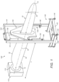
- Figure 1 shows a test apparatus 100 for torsional static testing of a wind turbine blade 10 to which the apparatus 100 is secured.
- the wind turbine blade 10 has a root end 12 and an opposed tip end 14. Between the root end 12 and the tip end 14 is an airfoil region having a profiled contour that includes a pressure side and a suction side, as well as a leading edge 16 and a trailing edge 18.
- An edgewise direction 20 extends between the leading and trailing edges 16, 18.
- the edgewise direction 20 may change along the length of the blade 10 as the shape of the blade 10 twists between the root and tip ends 12, 14.
- the test apparatus 100 comprises a test stand 110, a load frame 120, and actuators 130 operating on either side of the longitudinal axis of the blade 10 for applying a couple, and hence a torsional load, to the blade 10 via the load frame 120.
- the test apparatus 100 also includes a support frame 140 providing fixed mounting, fixed relative to the ground, for the actuators 130 and by which the load frame 120 may be supported when not secured to the blade.
- the test stand 110 is mounted on a ground surface, such as the floor or a steel hub mounted to the floor, and includes a rigid mount 112 for fixedly supporting the root end 12 of the blade 10 such that the edgewise direction 20 of the blade is substantially vertical and the longitudinal direction 22 of the blade 10 is substantially horizontal, as shown in Figure 1 .
- the rigid mount 112 may comprise any suitable connection means for attachment to the blade 10.
- the rigid mount may comprise a plurality of threaded bolts extending from the test stand 110 which are screwed into corresponding threaded bolt holes (not shown) at the root end 12 of the blade.
- the load frame 120 is secured around the wind turbine blade 10 at a position between the root end 12 and tip end 14 of the blade 10 and at a distance L from the root end 12.
- the load frame 120 comprises an outer frame 122 and an insert 124 arranged within the outer frame 122.
- the load frame 120 is pivotally connected to the actuators 130 on either side by mounting points 126 on the outer frame 122.
- the mounting points 126 are in the form of horizontally orientated pivot pins which allow the load frame 120 to be articulated relative to the actuators 130 about a horizontal axis 127 which is parallel to the longitudinal direction of the blade.
- the outer frame 122 is formed from two parallel sheets of metal, such as aluminium, which are secured together. In this manner, the outer frame 122 has a structure which is strong in the plane of the couple applied by the actuators 130 while still being relatively light.
- the sheets from which the outer frame 122 is made are cut out in the region adjacent to the mounting points 126 to further reduce the overall weight of the load frame 120 and the material required.
- the outer frame narrows towards its upper end to remove the need for material outside of the load path from the actuators 130 to the blade.
- the insert 124 is formed from a soft or slightly resilient material and its inner surface 125 defines a profiled aperture 128 corresponding to the profile or cross-section of the wind turbine blade at the position along the length of the blade at which the load frame 120 is to be mounted. That is, referring to Figures 1 and 2 , the shape of the profiled aperture 128 corresponds to the profile or cross-section of the wind turbine blade at the distance L from the root end 12 of the blade 10. This means that the profile of the blade is entirely enclosed within the insert 124 such that the inner surface 125 of the insert 124 is in contact with the outer surface of wind turbine blade around substantially the entire profile of the blade.
- the insert 124 may be shaped such that one or both ends of the aperture 128 terminate at a narrow angle corresponding to an edge of the blade profile.
- a stress reduction portion is provided in the insert 124 in the form of a circular hole 129 which intersects with the profiled aperture 128 towards its upper end.
- the upper end of the aperture 128 is arranged to receive the trailing edge of the blade, which is typically the thinnest portion of the blade profile.
- the circular hole 129 increases the radius of curvature at the upper end of the aperture 128 to reduce the stress concentration in this region. This may help to reduce crack propagation which may otherwise occur in the insert 124.
- the hole 129 also provides a channel in the insert 124 through which instrumentation cables may run from one side of the load frame to the other.
- the insert 124 may be made from any suitable soft or resilient material that is capable of transmitting the torsional loads from the actuators 130 to the blade without damaging the outer surface of the blade.
- the insert is made from Divinycell(RTM) H130, available from Diab International AB of Helsingborg Sweden.
- RTM Divinycell
- the insert 124 is soft or resilient, it forms a soft surface against the blade. This may improve the degree to which the load frame 120 conforms to the contours of the blade profile relative to conventional inserts, such as wood inserts. This allows the load frame to apply a more evenly distributed load across the surface of the blade. It also reduces the occurrence of locally increased pressure points which may otherwise cause the test results to be less representative of the actual stresses and strains experienced by the blade during operation.
- the softness or resilience of the insert 124 may also allow the load frame to absorb certain shock loads which may otherwise be transmitted directly to the blade surface.
- the actuators 130 each comprise a linear actuator having a cylinder 132 and a piston 134 that is slidable within the cylinder 132.
- each actuator may comprise any suitable actuator, for example a rotary actuator connected to its respective mounting point by a cable, chain or harness.
- Each actuator 130 has a fixed mounting point fixed relative to the ground at its lower end and is articulated to the support frame 140 to allow the base of the actuator 130 to pivot relative to the support frame about a horizontal pivot axis 137 which is parallel to the pivot axis 127 between the piston 134 and the load frame 120.
- each piston 134 is shown in a mid-stroke position, i.e. mid way between the fully retracted and fully extended positions.
- the load frame 120 is rotationally aligned and no torsional loads are applied to the blade by the load frame 120.
- the actuators 130 are arranged on either side of the longitudinal axis of the blade and are both positioned beneath the blade so that extension of the piston from the cylinder results in a generally upward vertical force on the load frame.
- the actuators could be connected to the support frame such that one pushes down on the load frame while the other pushes up on the load frame.
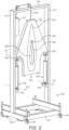
- the support frame 140 includes two parallel uprights 141 connected at their upper ends by a crossbeam 142 and connected at their lower ends by a support base 143.
- the support base 143 includes wheels 144 on its underside by which the support frame 140 may be moved to adjust its position relative to the blade.
- the support base 143 also includes a plurality of feet 145 on its underside by which the support frame 140 may be supported in a fixed manner.
- the feet include suction pads on their undersides to allow the support frame to be anchored to a floor surface during use.
- the wheels 144 are selectively retractable upwards to allow the support frame to rest on the feet 145 once the support frame is in the correct position.
- the support base can carry additional weights (not shown) to further limit movement of the support frame during use.
- the uprights 141 each include an actuator mount 146 at which ends of the actuators 130 are fixed relative to the ground, although being pivotally connected to the support frame 140.
- the support frame 140 also includes a weight block 147 connected to the load frame 120 by a cable 148 and pulleys.
- the weight block, cable and pulley arrangement acts as a counterweight to bear at least a portion of the weight of the load frame 120. This reduces the load on the actuators 130 caused by the weight of the load frame 120 when the load frame 120 is not mounted on the blade. It also reduces the amount of edgewise loading of the blade due to the weight of the load frame during use. This may improve the accuracy of the results obtained from a torsional test by reducing or minimising blade motion which is caused by edgewise loading. This may ensure that the measurements of blade motion obtained are limited to motion caused by torsional loading only.
- the load frame 120, actuators 130 and support frame 140 are moved together to the tip end of the blade and the insert 124 placed over the tip end.
- the support frame 140 is then moved towards the test stand 110 to slide the load frame 120 along the length of the blade towards the root end until the correct position along the length of the blade is reached at which point the insert fits securely against blade surface.
- one of the pair of actuators 130 is extended while the other is simultaneously retracted in an opposite manner by actuator drive means (not shown), such as a hydraulic or pneumatic pump or an electrical motor, to apply a couple to the load frame 120 about the longitudinal direction of the blade.
- actuator drive means such as a hydraulic or pneumatic pump or an electrical motor
- This couple is transferred to the blade by the insert to twist the blade about its longitudinal direction and thereby generate a torsional load.
- the torsional load generated during the static torsional test is selected to evaluate torsional stiffness of the blade. It may also be selected to represent the ultimate load to which the blade is expected to be subjected during its design service life.
- the degree to which each actuator is extended or retracted should mirror that of the other actuator to minimise vertical bending loads applied to the blade by the test apparatus.
- the torsional loads are applied by a profiled insert and applied across substantially the entire profile of the blade, the torsional stresses and strains generated in the blade by the test apparatus 100 are more representative of actual operating conditions.
- the blade is subjected to less deflection under its own weight.
- the torsional stiffness of the blade can be assessed with the blade in a state of deflection which is more representative of its actual state during operation, resulting in more accurate test results.
- Improved knowledge of the torsional stiffness of the blade can also allow design to avoid resonance of the blade, such as flutter, during operation.
- a more accurate torsional test can also reduce "over engineering" of the blade from seeking to achieve the required performance during less representative tests in which the strains are higher.
- the outer frame 122 and the insert 124 are each provided as a single, closed structure. In other examples, one or both of the outer frame 122 and the insert 124 may be provided in two or more discrete elements. This allows the load frame to be assembled around the blade at the testing position by fixing the frame elements together. This avoids the need for sliding along the length of the blade. This may be useful, for example, where other items of testing equipment, such as strain gauges or other load frames, are attached to the blade prior to mounting of the load frame.
- test apparatus for performing a static torsional test
- test apparatus could be used to perform a fatigue torsional test, if required, by exerting a cyclical loading cycle on the load frame using the actuators.
Landscapes
- Engineering & Computer Science (AREA)
- Aviation & Aerospace Engineering (AREA)
- Physics & Mathematics (AREA)
- General Physics & Mathematics (AREA)
- Life Sciences & Earth Sciences (AREA)
- Sustainable Development (AREA)
- Sustainable Energy (AREA)
- Chemical & Material Sciences (AREA)
- Combustion & Propulsion (AREA)
- Mechanical Engineering (AREA)
- General Engineering & Computer Science (AREA)
- Wind Motors (AREA)
- Investigating Strength Of Materials By Application Of Mechanical Stress (AREA)
Claims (10)
- Prüfeinrichtung zur Torsionsprüfung eines Windkraftanlagenblattes, umfassend:einen Prüfstand (110) zum starren Tragen eines Wurzelendes des Windkraftanlagenblattes;einen Lastrahmen (120) zur Montage auf dem Windkraftanlagenblatt an einer Prüfposition entlang der Länge des Windkraftanlagenblattes;und ein Paar Betätigungsvorrichtungen (130), die mit dem Lastrahmen zum Ausüben einer Kraft darauf verbunden sinddadurch gekennzeichnet, dass:der Prüfstand das Blatt in einer Ausrichtung mit dem Blatt in hochkantiger Richtung, im Wesentlichen vertikal stützt;der Lastrahmen (120) einen Außenrahmen (122) und einen profilierten Einsatz (124), der innerhalb des Außenrahmens gehalten wird, umfasst, wobei der profilierte Einsatz (124) eine profilierte Öffnung (128) definiert, die im Wesentlichen dem Profil des Windkraftanlagenblattes in der Prüfposition entspricht, sodass der profilierte Einsatz (124) im Gebrauch im Wesentlichen die Außenoberfläche von im Wesentlichen dem gesamten Profil des Windkraftanlagenblattes umschließt und damit in direktem Kontakt steht; unddas Paar Betätigungsvorrichtungen (130) auf einem Trägerrahmen (140) montiert ist, um einen festen Montagepunkt, der in Bezug zum Boden fixiert ist, bereitzustellen und mit dem Außenrahmen (122) des Lastrahmens (120) auf gegenüberliegenden Seiten der Blattlängsachse verbunden ist, wobei jeder in im Wesentlichen vertikalen, entgegengesetzten Richtungen wirkt, um das Windkraftanlagenblatt über den Lastrahmen um dessen Längsachse zu verdrehen.
- Prüfeinrichtung nach Anspruch 1, wobei der profilierte Einsatz (124) aus einem Material gebildet ist, das eine Druckfestigkeit von etwa 0,3 MPa bis etwa 10 MPa, vorzugsweise von etwa 1 MPa bis etwa 7 MPa, besonders bevorzugt von etwa 2 MPa bis etwa 4 MPa aufweist.
- Prüfeinrichtung nach Anspruch 1 oder Anspruch 2, wobei der profilierte Einsatz (124) ein Spannungsreduzierungsloch (129) umfasst, das sich mit einem Ende der profilierten Öffnung (128) schneidet, das einer Kante des Windkraftanlagenblattes entspricht, wobei das Spannungsreduzierungsloch (129) einen Krümmungsradius aufweist, der größer ist als der Krümmungsradius der Kante des Windkraftanlagenblattes.
- Prüfeinrichtung nach einem der Ansprüche 1 bis 3, bei jede Betätigungsvorrichtung an ihrem unteren Ende einen Montagepunkt aufweist, der in Bezug zum Boden fixiert ist, wo er an dem Trägerrahmen (140) angelenkt ist, und wobei beide Betätigungsvorrichtungen (130) unterhalb des Blattes positioniert sind.
- Prüfeinrichtung nach Anspruch 4, wobei der Trägerrahmen (140) zwei parallele Ständer (141) beinhaltet, die an ihren unteren Enden durch eine Trägerbasis (143) und an ihren oberen Enden durch einen Querträger (142) verbunden sind.
- Prüfeinrichtung nach Anspruch 5, wobei die Betätigungsvorrichtungen (130) auf gelenkige Weise an den Ständern (141) montiert sind.
- Prüfeinrichtung nach einem vorstehenden Anspruch, wobei der Trägerrahmen in Bezug zum Prüfstand (110) in der Richtung der Länge des Windkraftanlagenblattes einstellbar beweglich ist.
- Prüfeinrichtung nach einem vorstehenden Anspruch, wobei der Trägerrahmen (140) ein Gegengewicht (147) umfasst, das angeordnet ist, um zumindest einen Abschnitt des Gewichts des Lastrahmens zu tragen.
- Verfahren zur Torsionsprüfung eines Windkraftanlagenblattes, wobei das Verfahren umfasst:starres Tragen eines Wurzelendes des Windkraftanlagenblattes in einem Prüfstand (110), so dass die Längsrichtung des Blattes im Wesentlichen horizontal und die hochkantige Richtung des Blattes im Wesentlichen vertikal ist;Montieren eines Lastrahmens (120) an dem Windkraftanlagenblatt an einer Prüfposition entlang der Länge des Windkraftanlagenblattes, wobei der Lastrahmen (120) einen Außenrahmen (122) und einen profilierten Einsatz (124), der innerhalb des Außenrahmens gehalten wird, umfasst, wobei der profilierte Einsatz (124) eine profilierte Öffnung (128) definiert, die im Wesentlichen dem Profil des Windkraftanlagenblattes in der Prüfposition entspricht, sodass der profilierte Einsatz (124) im Gebrauch im Wesentlichen die Außenoberfläche von im Wesentlichen dem gesamten Profil des Windkraftanlagenblattes umschließt und damit in direktem Kontakt steht;Verbinden eines Paars Betätigungsvorrichtungen (130) zwischen festen Montagepunkten, die in Bezug zum Boden auf einem Trägerrahmen (140) und dem Lastrahmen (120) auf gegenüberliegenden Seiten der Blattlängsachse fixiert ist, wobei jeder in im Wesentlichen vertikalen, entgegengesetzten Richtungen wirkt; undDrehen des Windkraftanlagenblattes um seine Längsachse in der Prüfposition unter Verwendung der Betätigungsvorrichtungen (130), um ein Moment bereitzustellen, das auf den Lastrahmen (120) wirkt.
- Verfahren nach Anspruch 9, wobei der Schritt des Montierens des Lastrahmens (120) an dem Windkraftanlagenblatt durch Verschieben des Lastrahmens entlang der Länge des Blattes von einem Spitzenende des Blattes zur Prüfposition durchgeführt wird.
Applications Claiming Priority (2)
| Application Number | Priority Date | Filing Date | Title |
|---|---|---|---|
| DKPA201670952 | 2016-11-30 | ||
| PCT/DK2017/050398 WO2018099531A2 (en) | 2016-11-30 | 2017-11-29 | Torsional testing of a wind turbine blade |
Publications (2)
| Publication Number | Publication Date |
|---|---|
| EP3548741A2 EP3548741A2 (de) | 2019-10-09 |
| EP3548741B1 true EP3548741B1 (de) | 2025-01-22 |
Family
ID=62110822
Family Applications (1)
| Application Number | Title | Priority Date | Filing Date |
|---|---|---|---|
| EP17868506.1A Active EP3548741B1 (de) | 2016-11-30 | 2017-11-29 | Torsionsprüfung einer windturbinenschaufel |
Country Status (6)
| Country | Link |
|---|---|
| US (1) | US11579039B2 (de) |
| EP (1) | EP3548741B1 (de) |
| CN (1) | CN110177938B (de) |
| DK (1) | DK3548741T3 (de) |
| ES (1) | ES3009082T3 (de) |
| WO (1) | WO2018099531A2 (de) |
Families Citing this family (15)
| Publication number | Priority date | Publication date | Assignee | Title |
|---|---|---|---|---|
| GB2548589B (en) * | 2016-03-22 | 2020-06-17 | Vestas Wind Sys As | Fatigue testing of a wind turbine blade |
| KR102061831B1 (ko) * | 2018-04-17 | 2020-01-02 | 한국항공우주연구원 | 블레이드 구조 시험장치 및 이를 이용한 블레이드 시험방법 |
| JP7093063B2 (ja) * | 2019-04-12 | 2022-06-29 | 株式会社Ihi | 動翼の振動試験用治具 |
| EP3730916B1 (de) * | 2019-04-23 | 2021-10-13 | Siemens Gamesa Renewable Energy A/S | Anregungsvorrichtung und verfahren zur ermüdungsprüfung eines blattes einer windturbine |
| CN110146238B (zh) * | 2019-04-28 | 2025-01-10 | 广汽零部件有限公司 | 一种用于汽车座椅调角器扭转刚度测量的测量装置 |
| DK3816603T3 (da) | 2019-10-28 | 2023-06-12 | Siemens Gamesa Renewable Energy As | Indretning til lastemulator til en Vindmøllerotorvinge |
| CN111044381B (zh) * | 2019-12-27 | 2020-11-17 | 上海交通大学 | 变外形翼通用测试机构 |
| KR102252594B1 (ko) * | 2020-03-17 | 2021-05-17 | 주식회사 뉴원 | 풍력발전기용 소형 블레이드의 정ㆍ동적 시험장치 |
| FI3945014T3 (fi) * | 2020-07-30 | 2024-05-29 | Ge Energy Power Conversion Technology Ltd | Ulkoisen kuormituksen testauslaitteisto |
| CN111795899B (zh) * | 2020-07-30 | 2023-08-04 | 上海电气风电集团股份有限公司 | 一种扭转加载设备及叶片扭转测试方法 |
| CN112525737A (zh) * | 2020-11-20 | 2021-03-19 | 中国直升机设计研究所 | 一种测量直升机桨叶挥舞刚度的试验装置及试验方法 |
| CN114778087A (zh) * | 2021-12-29 | 2022-07-22 | 中材科技风电叶片股份有限公司 | 风电叶片扭转测试工装和风电叶片扭转测试方法 |
| CN118275020B (zh) * | 2022-12-30 | 2025-06-17 | 江苏金风科技有限公司 | 用于风机叶片的扭转测试系统和扭转测试方法 |
| CN118188350B (zh) * | 2024-04-08 | 2024-09-06 | 常州达姆斯检测技术有限公司 | 一种激振双轴弯扭耦合疲劳测试装置及方法 |
| CN120384849A (zh) * | 2025-05-19 | 2025-07-29 | 中国石油大学(华东) | 一种用于自然风下风电叶片颤振研究的缩比试验装置 |
Citations (1)
| Publication number | Priority date | Publication date | Assignee | Title |
|---|---|---|---|---|
| GB2488789A (en) * | 2011-03-07 | 2012-09-12 | Vestas Wind Sys As | A wind turbine blade tester |
Family Cites Families (16)
| Publication number | Priority date | Publication date | Assignee | Title |
|---|---|---|---|---|
| EP1518101A4 (de) * | 2002-07-03 | 2008-03-19 | Midwest Research Inst | Resonanztestsystem |
| US7434328B2 (en) * | 2005-01-21 | 2008-10-14 | Sikorsky Aircraft Corporation | Rotor blade cuff measuring tool |
| EP2162721B1 (de) | 2007-05-30 | 2019-10-30 | Vestas Wind Systems A/S | Verfahren zum testen von windradflügeln |
| WO2009135136A2 (en) | 2008-05-02 | 2009-11-05 | Alliance For Sustainable Energy, Llc | Base excitation testing system using spring elements to pivotally mount wind turbine blades |
| EP2392818A1 (de) * | 2009-01-30 | 2011-12-07 | Gamesa Innovation & Technology, S.L. | System zur messung von deformationen bei windturbinenschaufeln während einer statischen prüfung |
| EP2555970A1 (de) * | 2010-01-19 | 2013-02-13 | Modular Wind Energy, Inc. | Systeme und verfahren zur durchführung von strukturtests auf windturbinenschaufeln |
| CH702812B1 (de) * | 2010-03-10 | 2014-09-30 | George Cant | Einrichtung zur Bestimmung von Materialeigenschaften von Snowboards oder Ski. |
| US8418560B2 (en) * | 2011-07-28 | 2013-04-16 | General Electric Company | Composite fiber wave inspection system and method |
| DE102012205153B4 (de) * | 2012-03-29 | 2013-10-17 | Repower Systems Se | Prüfvorrichtung und Schwingmassenanordnung für ein Rotorblatt einer Windenergieanlage |
| DE102012111844B4 (de) * | 2012-12-05 | 2015-07-23 | Industrieanlagen-Betriebsgesellschaft Mbh | Prüfstand für ein Rotorblatt oder ein Rotorblattsegment und Anordnung mit einem derartigen Prüfstand |
| KR101418322B1 (ko) * | 2013-05-16 | 2014-07-14 | 한국기계연구원 | 이송질량의 비를 최대화한 블레이드 피로시험용 공진발생장치 및 이를 이용한 피로시험 방법 |
| CN103398840A (zh) | 2013-07-29 | 2013-11-20 | 山东理工大学 | 风机叶片的疲劳加载与重力补偿装置及其试验方法 |
| CN105593661B (zh) * | 2014-05-21 | 2018-10-30 | 韩国机械研究院 | 用于叶片疲劳测试的具有最大化移动质量比的共振发生装置和使用该共振发生装置的疲劳测试方法 |
| DE102014218518A1 (de) * | 2014-09-16 | 2016-03-17 | Dr. Johannes Heidenhain Gmbh | Vorrichtung zur Erfassung von Verformungen eines Rotorblatts und Verfahren zur Montage einer derartigen Vorrichtung |
| EP3198255B1 (de) * | 2014-09-26 | 2019-01-09 | Vestas Wind Systems A/S | Ermüdungsprüfung einer windturbinenschaufel |
| DE102017118375A1 (de) * | 2017-08-11 | 2019-02-14 | Innogy Se | Offshore Bauwerk |
-
2017
- 2017-11-29 EP EP17868506.1A patent/EP3548741B1/de active Active
- 2017-11-29 DK DK17868506.1T patent/DK3548741T3/da active
- 2017-11-29 ES ES17868506T patent/ES3009082T3/es active Active
- 2017-11-29 US US16/464,897 patent/US11579039B2/en active Active
- 2017-11-29 CN CN201780082954.3A patent/CN110177938B/zh active Active
- 2017-11-29 WO PCT/DK2017/050398 patent/WO2018099531A2/en not_active Ceased
Patent Citations (1)
| Publication number | Priority date | Publication date | Assignee | Title |
|---|---|---|---|---|
| GB2488789A (en) * | 2011-03-07 | 2012-09-12 | Vestas Wind Sys As | A wind turbine blade tester |
Also Published As
| Publication number | Publication date |
|---|---|
| WO2018099531A2 (en) | 2018-06-07 |
| ES3009082T3 (en) | 2025-03-26 |
| CN110177938B (zh) | 2021-02-26 |
| CN110177938A (zh) | 2019-08-27 |
| EP3548741A2 (de) | 2019-10-09 |
| US11579039B2 (en) | 2023-02-14 |
| DK3548741T3 (da) | 2025-02-17 |
| WO2018099531A3 (en) | 2018-08-30 |
| US20200011760A1 (en) | 2020-01-09 |
Similar Documents
| Publication | Publication Date | Title |
|---|---|---|
| EP3548741B1 (de) | Torsionsprüfung einer windturbinenschaufel | |
| US10209160B2 (en) | Fatigue testing of a wind turbine blade | |
| EP3433594B1 (de) | Ermüdungsprüfung einer windturbinenschaufel | |
| CN110411722B (zh) | 一种结构静力与疲劳试验装置 | |
| JP3242177U (ja) | 風力タービンブレードのねじり疲労試験装置 | |
| CN105190284B (zh) | 用于叶片疲劳测试的具有减少的侧向负载的共振发生装置 | |
| EP2623768B1 (de) | Heberahmen zum Heben eines Windturbinenblatts, Verfahren zum Montieren eines Windturbinenblatts auf eine Windturbinennabe und Verfahren zum Anordnen eines Windturbinenrotors | |
| KR101418322B1 (ko) | 이송질량의 비를 최대화한 블레이드 피로시험용 공진발생장치 및 이를 이용한 피로시험 방법 | |
| CA2521045A1 (en) | Control of power, loads and/or stability of a horizontal axis wind turbine by use of variable blade geometry control | |
| MX2010005030A (es) | Superficies de control activo para paletas de turbina eolica. | |
| DK2469087T3 (en) | Biased stiffening system for a wind turbine generator sheath | |
| CN103245576A (zh) | 风力发电叶片疲劳测试试验装置及试验方法 | |
| KR101179229B1 (ko) | 인장력 및 회전력 동시 부가 장치 | |
| EP2674740A1 (de) | Ermüdungsprüfungsvorrichtung für eine Windturbinenschaufel | |
| CN213336734U (zh) | 一种风机叶片扭转疲劳试验装置 | |
| CN114166489B (zh) | 一种刚性主桨毂连接件的加载试验装置 | |
| EP3526468B1 (de) | Windturbinenschaufel mit variabler auslenkungsabhängiger steifigkeit | |
| CN113670739B (zh) | 一种直升机主旋叶片疲劳试验装置 | |
| CN116429363A (zh) | 一种风电叶片疲劳测试装置及其测试方法 | |
| WO2024223888A2 (en) | Wind turbine blade specimen testing | |
| CN112504869A (zh) | 一种柔性材料的加载装置 | |
| US12473084B1 (en) | Teetering rotor yoke with pitched arms | |
| CN218787893U (zh) | 安装结构和风力涡轮机叶片部分测试组件 | |
| EP2857675B1 (de) | Formen eines gekrümmten Rotorblatts | |
| CN114112351A (zh) | 一种主桨叶翼型段标定装置 |
Legal Events
| Date | Code | Title | Description |
|---|---|---|---|
| STAA | Information on the status of an ep patent application or granted ep patent |
Free format text: STATUS: UNKNOWN |
|
| STAA | Information on the status of an ep patent application or granted ep patent |
Free format text: STATUS: THE INTERNATIONAL PUBLICATION HAS BEEN MADE |
|
| PUAI | Public reference made under article 153(3) epc to a published international application that has entered the european phase |
Free format text: ORIGINAL CODE: 0009012 |
|
| STAA | Information on the status of an ep patent application or granted ep patent |
Free format text: STATUS: REQUEST FOR EXAMINATION WAS MADE |
|
| 17P | Request for examination filed |
Effective date: 20190619 |
|
| AK | Designated contracting states |
Kind code of ref document: A2 Designated state(s): AL AT BE BG CH CY CZ DE DK EE ES FI FR GB GR HR HU IE IS IT LI LT LU LV MC MK MT NL NO PL PT RO RS SE SI SK SM TR |
|
| AX | Request for extension of the european patent |
Extension state: BA ME |
|
| DAV | Request for validation of the european patent (deleted) | ||
| DAX | Request for extension of the european patent (deleted) | ||
| STAA | Information on the status of an ep patent application or granted ep patent |
Free format text: STATUS: EXAMINATION IS IN PROGRESS |
|
| 17Q | First examination report despatched |
Effective date: 20220504 |
|
| GRAP | Despatch of communication of intention to grant a patent |
Free format text: ORIGINAL CODE: EPIDOSNIGR1 |
|
| STAA | Information on the status of an ep patent application or granted ep patent |
Free format text: STATUS: GRANT OF PATENT IS INTENDED |
|
| INTG | Intention to grant announced |
Effective date: 20240814 |
|
| GRAS | Grant fee paid |
Free format text: ORIGINAL CODE: EPIDOSNIGR3 |
|
| GRAA | (expected) grant |
Free format text: ORIGINAL CODE: 0009210 |
|
| STAA | Information on the status of an ep patent application or granted ep patent |
Free format text: STATUS: THE PATENT HAS BEEN GRANTED |
|
| AK | Designated contracting states |
Kind code of ref document: B1 Designated state(s): AL AT BE BG CH CY CZ DE DK EE ES FI FR GB GR HR HU IE IS IT LI LT LU LV MC MK MT NL NO PL PT RO RS SE SI SK SM TR |
|
| REG | Reference to a national code |
Ref country code: GB Ref legal event code: FG4D |
|
| REG | Reference to a national code |
Ref country code: CH Ref legal event code: EP |
|
| REG | Reference to a national code |
Ref country code: IE Ref legal event code: FG4D |
|
| REG | Reference to a national code |
Ref country code: DE Ref legal event code: R096 Ref document number: 602017087479 Country of ref document: DE |
|
| REG | Reference to a national code |
Ref country code: DK Ref legal event code: T3 Effective date: 20250211 |
|
| P01 | Opt-out of the competence of the unified patent court (upc) registered |
Free format text: CASE NUMBER: APP_6865/2025 Effective date: 20250210 |
|
| REG | Reference to a national code |
Ref country code: ES Ref legal event code: FG2A Ref document number: 3009082 Country of ref document: ES Kind code of ref document: T3 Effective date: 20250326 |
|
| REG | Reference to a national code |
Ref country code: NL Ref legal event code: MP Effective date: 20250122 |
|
| PG25 | Lapsed in a contracting state [announced via postgrant information from national office to epo] |
Ref country code: NL Free format text: LAPSE BECAUSE OF FAILURE TO SUBMIT A TRANSLATION OF THE DESCRIPTION OR TO PAY THE FEE WITHIN THE PRESCRIBED TIME-LIMIT Effective date: 20250122 |
|
| PG25 | Lapsed in a contracting state [announced via postgrant information from national office to epo] |
Ref country code: RS Free format text: LAPSE BECAUSE OF FAILURE TO SUBMIT A TRANSLATION OF THE DESCRIPTION OR TO PAY THE FEE WITHIN THE PRESCRIBED TIME-LIMIT Effective date: 20250422 |
|
| PG25 | Lapsed in a contracting state [announced via postgrant information from national office to epo] |
Ref country code: FI Free format text: LAPSE BECAUSE OF FAILURE TO SUBMIT A TRANSLATION OF THE DESCRIPTION OR TO PAY THE FEE WITHIN THE PRESCRIBED TIME-LIMIT Effective date: 20250122 |
|
| PG25 | Lapsed in a contracting state [announced via postgrant information from national office to epo] |
Ref country code: PL Free format text: LAPSE BECAUSE OF FAILURE TO SUBMIT A TRANSLATION OF THE DESCRIPTION OR TO PAY THE FEE WITHIN THE PRESCRIBED TIME-LIMIT Effective date: 20250122 |
|
| REG | Reference to a national code |
Ref country code: LT Ref legal event code: MG9D |
|
| PG25 | Lapsed in a contracting state [announced via postgrant information from national office to epo] |
Ref country code: IS Free format text: LAPSE BECAUSE OF FAILURE TO SUBMIT A TRANSLATION OF THE DESCRIPTION OR TO PAY THE FEE WITHIN THE PRESCRIBED TIME-LIMIT Effective date: 20250522 Ref country code: NO Free format text: LAPSE BECAUSE OF FAILURE TO SUBMIT A TRANSLATION OF THE DESCRIPTION OR TO PAY THE FEE WITHIN THE PRESCRIBED TIME-LIMIT Effective date: 20250422 |
|
| REG | Reference to a national code |
Ref country code: AT Ref legal event code: MK05 Ref document number: 1761641 Country of ref document: AT Kind code of ref document: T Effective date: 20250122 |
|
| PG25 | Lapsed in a contracting state [announced via postgrant information from national office to epo] |
Ref country code: HR Free format text: LAPSE BECAUSE OF FAILURE TO SUBMIT A TRANSLATION OF THE DESCRIPTION OR TO PAY THE FEE WITHIN THE PRESCRIBED TIME-LIMIT Effective date: 20250122 |
|
| PG25 | Lapsed in a contracting state [announced via postgrant information from national office to epo] |
Ref country code: LV Free format text: LAPSE BECAUSE OF FAILURE TO SUBMIT A TRANSLATION OF THE DESCRIPTION OR TO PAY THE FEE WITHIN THE PRESCRIBED TIME-LIMIT Effective date: 20250122 Ref country code: PT Free format text: LAPSE BECAUSE OF FAILURE TO SUBMIT A TRANSLATION OF THE DESCRIPTION OR TO PAY THE FEE WITHIN THE PRESCRIBED TIME-LIMIT Effective date: 20250522 |
|
| PG25 | Lapsed in a contracting state [announced via postgrant information from national office to epo] |
Ref country code: BG Free format text: LAPSE BECAUSE OF FAILURE TO SUBMIT A TRANSLATION OF THE DESCRIPTION OR TO PAY THE FEE WITHIN THE PRESCRIBED TIME-LIMIT Effective date: 20250122 Ref country code: GR Free format text: LAPSE BECAUSE OF FAILURE TO SUBMIT A TRANSLATION OF THE DESCRIPTION OR TO PAY THE FEE WITHIN THE PRESCRIBED TIME-LIMIT Effective date: 20250423 |
|
| PG25 | Lapsed in a contracting state [announced via postgrant information from national office to epo] |
Ref country code: AT Free format text: LAPSE BECAUSE OF FAILURE TO SUBMIT A TRANSLATION OF THE DESCRIPTION OR TO PAY THE FEE WITHIN THE PRESCRIBED TIME-LIMIT Effective date: 20250122 |
|
| PG25 | Lapsed in a contracting state [announced via postgrant information from national office to epo] |
Ref country code: SE Free format text: LAPSE BECAUSE OF FAILURE TO SUBMIT A TRANSLATION OF THE DESCRIPTION OR TO PAY THE FEE WITHIN THE PRESCRIBED TIME-LIMIT Effective date: 20250122 |
|
| PG25 | Lapsed in a contracting state [announced via postgrant information from national office to epo] |
Ref country code: SM Free format text: LAPSE BECAUSE OF FAILURE TO SUBMIT A TRANSLATION OF THE DESCRIPTION OR TO PAY THE FEE WITHIN THE PRESCRIBED TIME-LIMIT Effective date: 20250122 |
|
| PG25 | Lapsed in a contracting state [announced via postgrant information from national office to epo] |
Ref country code: IT Free format text: LAPSE BECAUSE OF FAILURE TO SUBMIT A TRANSLATION OF THE DESCRIPTION OR TO PAY THE FEE WITHIN THE PRESCRIBED TIME-LIMIT Effective date: 20250122 |
|
| PG25 | Lapsed in a contracting state [announced via postgrant information from national office to epo] |
Ref country code: EE Free format text: LAPSE BECAUSE OF FAILURE TO SUBMIT A TRANSLATION OF THE DESCRIPTION OR TO PAY THE FEE WITHIN THE PRESCRIBED TIME-LIMIT Effective date: 20250122 Ref country code: CZ Free format text: LAPSE BECAUSE OF FAILURE TO SUBMIT A TRANSLATION OF THE DESCRIPTION OR TO PAY THE FEE WITHIN THE PRESCRIBED TIME-LIMIT Effective date: 20250122 |
|
| REG | Reference to a national code |
Ref country code: DE Ref legal event code: R097 Ref document number: 602017087479 Country of ref document: DE |
|
| PG25 | Lapsed in a contracting state [announced via postgrant information from national office to epo] |
Ref country code: RO Free format text: LAPSE BECAUSE OF FAILURE TO SUBMIT A TRANSLATION OF THE DESCRIPTION OR TO PAY THE FEE WITHIN THE PRESCRIBED TIME-LIMIT Effective date: 20250122 |
|
| PG25 | Lapsed in a contracting state [announced via postgrant information from national office to epo] |
Ref country code: SK Free format text: LAPSE BECAUSE OF FAILURE TO SUBMIT A TRANSLATION OF THE DESCRIPTION OR TO PAY THE FEE WITHIN THE PRESCRIBED TIME-LIMIT Effective date: 20250122 |
|
| PLBE | No opposition filed within time limit |
Free format text: ORIGINAL CODE: 0009261 |
|
| STAA | Information on the status of an ep patent application or granted ep patent |
Free format text: STATUS: NO OPPOSITION FILED WITHIN TIME LIMIT |