EP3548228B1 - Unterbetätigte roboterhand - Google Patents
Unterbetätigte roboterhand Download PDFInfo
- Publication number
- EP3548228B1 EP3548228B1 EP17826277.0A EP17826277A EP3548228B1 EP 3548228 B1 EP3548228 B1 EP 3548228B1 EP 17826277 A EP17826277 A EP 17826277A EP 3548228 B1 EP3548228 B1 EP 3548228B1
- Authority
- EP
- European Patent Office
- Prior art keywords
- rotation
- fingers
- finger
- stage
- phalanx
- Prior art date
- Legal status (The legal status is an assumption and is not a legal conclusion. Google has not performed a legal analysis and makes no representation as to the accuracy of the status listed.)
- Active
Links
Images




Classifications
-
- B—PERFORMING OPERATIONS; TRANSPORTING
- B25—HAND TOOLS; PORTABLE POWER-DRIVEN TOOLS; MANIPULATORS
- B25J—MANIPULATORS; CHAMBERS PROVIDED WITH MANIPULATION DEVICES
- B25J15/00—Gripping heads and other end effectors
- B25J15/0009—Gripping heads and other end effectors comprising multi-articulated fingers, e.g. resembling a human hand
-
- B—PERFORMING OPERATIONS; TRANSPORTING
- B25—HAND TOOLS; PORTABLE POWER-DRIVEN TOOLS; MANIPULATORS
- B25J—MANIPULATORS; CHAMBERS PROVIDED WITH MANIPULATION DEVICES
- B25J15/00—Gripping heads and other end effectors
- B25J15/02—Gripping heads and other end effectors servo-actuated
- B25J15/0206—Gripping heads and other end effectors servo-actuated comprising articulated grippers
- B25J15/0213—Gripping heads and other end effectors servo-actuated comprising articulated grippers actuated by gears
-
- B—PERFORMING OPERATIONS; TRANSPORTING
- B25—HAND TOOLS; PORTABLE POWER-DRIVEN TOOLS; MANIPULATORS
- B25J—MANIPULATORS; CHAMBERS PROVIDED WITH MANIPULATION DEVICES
- B25J15/00—Gripping heads and other end effectors
- B25J15/08—Gripping heads and other end effectors having finger members
Definitions
- the present industrial invention relates to an underactuated robotic hand.
- robot hand relates to an end-effector with an anthropomorphic inspiration. Due to the human hand complexity, the creation of a mechanism able to reproduce accurately its functions is very challenging.
- the robotic hands proposed in literature can be divided in three main categories, according to the number of their degrees of freedom (DOFs) and of their degrees of actuation (DOAs): fully-actuated, underactuated and redundantly actuated.
- Fully-actuated robotic hands have a number of degrees of freedom equal to the number of degrees of actuation.
- Underactuated robotic hands have a number of degrees of freedom higher than the number of degrees of actuation.
- Redundantly actuated robotic hands have a number of degrees of freedom lower than the number of degrees of actuation.
- Fully-actuated robotic hands, while capable of efficient grasping, are extremely complex, and this leads to high costs and an overall lack of robustness. This is especially true for redundantly actuated robotic hands. This is the main reason why, recently, an increasing interest in underactuated designs can be found.
- the basic idea of the underactuation in robotic grasping is to use a mechanical system which, by means of passive elements such as springs and mechanical limits, can automatically adapt to the specific shape of the grasped object, so that the number or required actuators is lower than the number of the manipulator DOFs. This results in simpler control systems and in a reduction of the manipulator costs.
- One of the manners to obtain an underactuated mechanism is to use differential systems, which automatically distribute one input to several outputs, the ratio between such outputs being defined by their kinematic state and by the design parameters of the mechanism itself.
- a differential mechanism is a "mechanism for which the degree of freedom is two and which may accept two inputs to produce one output or, may resolve a single input into two outputs".
- differential modules In order to obtain more than two outputs, multiple differential modules can be used, configured in series or in parallel according to needs, each one adding 1 DOF to the system. In general, (n-1) differential stages are required to obtain n outputs.
- an underactuated robotic hand which overcomes the drawbacks linked to the known state of the art, and which allows, in particular, the actuation of all the fingers, comprised the thumb, by means of only one motor, which is robust and compact and which allows a simple substitution of the fingers, for example in case of failure.
- Another technical problem is to provide a highly underactuated robotic hand, with a mechanism based on gears and toothed belts and without using unidirectional actuation means, such as tendons.
- the present invention provides an underactuated robotic hand controlled by only one motor in which the movement of the thumb can continue even if the other four fingers are all grasping an object.
- Yet another technical problem solved by the present invention is to provide an anthropomorphic hand with dimensions and weight comparable with the ones of a normal limb, by reducing the quantity of active components (motors) in order to reduce the weight of the device and to increase its usability.
- Another problem solved by the hand according to the present invention is to provide an underactuated robotic hand whose mechanism allows to imitate the human hand functionality as accurately as possible, and which allows in particular to distribute the tightening torque differently among the various fingers, as it occurs in a human hand.
- a technical problem solved by the present invention is to provide an underactuated robotic hand whose fingers phalanx dimensions, their aspect and the materials of which they are made can be modified without needing a re-design of the mechanism.
- the object of the present invention is defined in claim 1. It reaches the prefixed aims since it is an anthropomorphic robotic hand comprising: a palm and a metacarpus configured to rotate with respect to said palm around an axis of rotation; four fingers substantially aligned and constrained to said palm and a finger opposable to them, each one of said fingers constrained to the palm comprising at least a proximal phalanx, a middle phalanx and a distal phalanx, and said opposable finger comprising a proximal phalanx and a distal phalanx, the proximal phalanges of each one of said aligned fingers being hinged to said palm in respective axes of rotation and the proximal phalanx of said opposable finger being hinged to said metacarpus in respective axes of rotation; a motor; a plurality of bevel gear differential stages which transmit motion from said motor to said aligned fingers and to said opposable finger, characterized in that said plurality of differential stages comprises
- the sun gears of said second differential stage being integral to the planet carriers of a third and a fourth differential stage, the sun gears of said third and fourth differential stage being configured so that they respectively engage with four gears having axes coincident with said respective axes of rotation between the proximal phalanges of said aligned fingers and said palm.
- substantially aligned is referred to the position of the four fingers from the forefinger to the little finger, constrained to the palm, which in a human hand, even if not necessarily parallel to each other, have still a rest position in which they are parallel and a limited angular excursion in the hand horizontal plane.
- the mechanism has 20 degrees of freedom, of which 15 are controllable actively and bi-directionally by means of the only one motor provided (100) and 5 are passive and can be adapted in certain limits to the shape of the grasped object, but cannot be controlled actively.
- the elements of the five bevel gear differential stages are indicated with a number between 0 and 4 (identifying of the stage) followed by the number 4 for the planet carrier, 5 for the right sun gear and 6 for the left sun gear. So, for example, the planet carrier of the third stage is indicated with the reference (24).
- Phalanges are indicated with references made up of a number between 1 and 5 which identifies the finger, followed by the number 1 for the proximal phalanx, 2 for the middle phalanx, 3 for the distal phalanx and 0 for the metacarpus in the case of the thumb. Therefore, for example, the middle phalanx of the ring finger is indicated with the reference (42), the proximal phalanx of the thumb with the reference (11) and so on.
- the first pulley and the toothed belt connecting the following pulley are indicated with the reference of the finger followed by 10 and 11.
- the second pulley and the toothed belt connecting the following pulley are indicated with the reference of the finger followed by 20 and 21, and followed by 30 for the third pulley.
- the second pulley of the middle finger is indicated with the reference (320).
- reference 40 indicates the axis of rotation x (flexion/extension) and reference 41 the brake acting on such axis of rotation
- reference 60 indicates the axis of rotation z (abduction/adduction).
- the axis x of the little finger is indicated with (540), the respective brake with (541).
- the axis of rotation of the metacarpus with respect to the palm is indicated with (80) and the brake acting on such axis of rotation is indicated with (81).
- the planet carrier (04) of the first differential stage is moved directly by the motor (100), and the first differential stage transmits motion by means of the right sun gear (05) to the differential stages which move the four aligned fingers, and by means of the left sun gear (06) to the differential stage which moves the thumb.
- right and left sun gear are used also for the first and the fifth stage, indicating as left sun gear the one in the bottom in the figure.
- the planet carrier (04) of the first differential stage is the only gear directly moved by the motor, unlike what occurs in mechanisms known at the state of the art, as for example the one shown in fig. 9 - extracted by D1 - wherein the motor moves directly both the planet carrier P1 of the stage 1 and the sun gear S4R of the stage 4.
- the right sun gear (05) of the first differential stage engages with the planet carrier (14) of the second differential stage.
- the second differential stage distributes motion to the two following stages which respectively carry out the movement of forefinger and middle finger and the movement of ring finger and little finger.
- the movement is transmitted to the planet carrier (14) by the right sun gear (05) of the first differential stage, and it is then subdivided to the next differential stages, by means of the sun gears (15, 16).
- the left sun gear (16) of the second stage and the planet carrier (24) of the third stage are integral to each other.
- the axes of rotation of the planet carriers (24, 34) of third and fourth stage can be mounted inclined to the shafts of the sun gears (16, 15) of the second stage by interposition of a Cardan joint (161, 151) on respective connecting shafts, which allows the transmission of rotation between mutually inclined shafts. It is not needed that mutual inclination angles ( ⁇ , ⁇ ) are identical.
- the structure of the palm is realized in two portions (01) and (02) hinged by means of a Cardan joint (151) along an axis (600) belonging to the horizontal plane of the hand, passing through the center of the Cardan joint (151) and inclined of an angle ⁇ to the middle plane of the hand, during the grasping action the ring finger and the little finger (4, 5), in addition to flex, will converge towards the middle plane of the hand together with the right portion of the palm, rotating around the axis of rotation (600), opposing to the thumb and thus improving some kinds of grasps and the prosthesis anthropomorphism.
- the degree of freedom added in this way (the hinge between right and left portion of the palm) can be managed both actively by means of a second actuator and passively by using springs.
- the differential stages described so far are preferably bevel gear differential stages.
- motion is transmitted to the aligned fingers by the third and fourth differential stage.
- Each finger is made up of three phalanges, coupled-hinged to each other around a relative axis of rotation.
- the proximal phalanx of finger 1 is hinged to the metacarpus (10) around a relative axis of rotation, while the proximal phalanges of fingers from forefinger to ring finger and the metacarpus (10) are hinged to the palm of the hand, around a relative axis of rotation.
- the shape of the components is such that the rotation allowed around all the respective axes of rotation is limited to values similar to the physiological ones of the respective components of the human hand.
- the aligned fingers (from the forefinger to the little finger), with respect to the basic configuration with completely extended fingers, have the possibility to flex the proximal phalanx between about 90° and 110°, the middle phalanx between 90° and 135° and the distal phalanx between 85 and 90°.
- Concerning the thumb instead, always as a rough guide, the proximal phalanx flexion can reach about 70°, the distal phalanx flexion about 75°, while the metacarpus can have an adduction of about 90°.
- the device according to the present invention can be realized with at least a portion of the mechanical limits not rigid, with particular reference to the limits concerning the fingers hyper-extension.
- an elastic material can be used, with a rigidity high enough to block the fingers extension beyond the basic position when these are actuated simply by the motor, and at the same time characterized by a sufficient compliance when the fingers are stressed passively.
- the mechanical limits at the knuckles have a rigidity not high enough to be deformed when the motor exerts the maximum couple, but they are deformable when the prosthesis fingers are leant on a table and the palm is bent inwards.
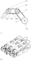
- the forefinger is hinged to the palm of the hand at the axis of rotation (240) between proximal phalanx (21) and palm (00).
- the first toothed pulley (210) is positioned at such axis, engages with the left sun gear (26) of the third differential stage and is idler with respect to its axis of rotation.
- the first toothed pulleys of each finger are conveniently made up of a gear integral to a toothed pulley.
- the gear engages with the respective sun gear of the bevel gear differential stages, while the tooted pulley is connected to the following pulley by means of a toothed belt.
- the first pulley (210) is connected by means of the toothed belt (211) to the second toothed pulley (220), which is idler to the relative axis of rotation (250) between the proximal phalanx (21) and the middle phalanx (22) of the forefinger.
- This last pulley (220) is also connected by means of a second toothed belt (221) to the third toothed pulley (230), which has the axis coincident with the relative axis of rotation between the middle phalanx (22) and the distal phalanx (23), and it is integral to this last one.
- the motion of the left sun gear (26) of the second differential stage, frictions being omitted for simplicity, is directly transmitted to the pulley (230) integral to the distal phalanx (23) of the forefinger, while the proximal (21) and middle phalanges (22) do not move.
- the distal phalanx (23) comes in contact with the object to be grasped or reaches its mechanical limit, its movement is blocked and the third pulley (230), which is integral to the distal phalanx, cannot rotate anymore.
- the ring finger and the little finger function similarly, and they are moved by the fourth differential stage, respectively by means of the left (36) and right (35) sun gear.
- the left sun gear (06) of the first differential stage engages with the planet carrier (44) of the fifth differential stage, which distributes the torque between the adduction/abduction movements (controlled by the left sun gear 46) and flexion/extension (controlled by the right sun gear 45) of the thumb.
- the left sun gear (46) is integral to the metacarpus (10), so when it is actuated the whole metacarpus (10) rotates around the axis (180), carrying out the adduction/abduction movement.
- Such axis (180) should not necessarily coincide with the axis of rotation of the stage 0, as it is shown in figure 2 , but it can have a relative inclination with respect to this one with the aim of making the manipulator more similar to a human hand.
- the sun gear 06 and the planet carrier 44 will be conical gears, apt to be engaged with said relative inclination.
- the right sun gear (45) engages with the gear (47), which in turn transmits the motion to the pulley 110, thus allowing the thumb flexion/extension.
- the motor (100) is forced to stop.
- the maximum torque exerted is determined and, in this way, also the maximum torque transmitted to the fingers, which determines the grasping force.
- the grasping force control can be carried out by current-controlling the motor, and this can be easily done in a plurality of ways.
- current can be controlled as a function of the number of signals read by control electrodes in a predetermined period of time (for example: 1 signal in 1 second for a weak grip, 2 signals in 1 second for a medium-strength grip, 3 signals in 1 second for a strong grip).
- the current absorbed by the motor can be controlled as a function of the intensity of the signals detected by the electrodes, by correlating it in a directly proportional way or according to other calibration principle to be defined.
- the mechanism compactness allows to position also the control board (300) inside the manipulator, so that it acquires a higher degree of modularity. This is particularly useful when it is used by people with different amputation levels: for example, a "wrist” module and a “forearm” module can be added to the manipulator module in case of a transradial amputation, while in case of amputation under the wrist the manipulator module can be used alone.
- the motor torque is firstly divided (from the first differential stage) between the thumb and the other four fingers. This makes it possible that, at steady-state, the torque exerted by the thumb is equal to the sum of the torques exerted by the other fingers, which is an optimal condition to carry out the grip which require thumb opposing to the other fingers.
- the torque transmitted to the thumb is subdivided (from the fifth differential stage) between the adduction/abduction and flexion/extension movements, while the torque transmitted to the other four fingers is firstly subdivided (from the second differential stage) between forefinger and middle finger on one side and between ring finger and little finger on the other side, and finally (from the third and fourth differential stage) distributed to the single fingers.
- the automatic distribution of the torque according to the just described kinematic scheme makes it possible that, even by using just a single command (1 degree of actuation), the fingers automatically adapt to the shape of the grasped object, always developing the most stable grasp.
- bevel gear differential stages Another advantage of using bevel gear differential stages is the independence of the forces exerted by the sun gears with respect to their kinematic position.
- the bevel gear differential stages are globally force-isotropic, so independently of the kinematic position of the finger they exert a constant force, thus ensuring constant performances over the whole workspace.
- Such advantage is extended inside the fingers by using toothed belt drive, characterized by the transmitted forces independence from the pulleys wheelbase and from the phalanges relative inclination.
- springs which exert an elastic torque between the various hinged elements, preferably in the direction of the hand closing.
- the presence of springs allows to obtain a series of advantages.
- the springs allow to define the relative initial position between different fingers and between different phalanges of the same finger. This is particularly useful while assembling the device: it would be complex to set the starting position of the motor, corresponding to the hand completely closed by keeping all the joints in the correct position without the contribution of the springs which do it automatically.
- the ratio between the rigidities of the springs used in the various axes of rotation inside each single finger determines the closing order of the phalanges.
- it is important that the first phalanx to rotate is the proximal one, then the middle one and only in the end the distal one.
- proximal phalanges are hinged around a relative axis of rotation with respect to the palm. Obviously, from a constructive point of view, at such axis a shaft is present.
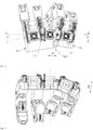
- the proximal phalanges are not directly in contact to such shaft, but a cylinder coaxial to the shaft (240) is interposed between the phalanx and the shaft, shown in figure 3 with reference to the forefinger as an example, realized in elastic material, which allows a certain degree of adduction/abduction of the fingers.
- this elastic cylinder (290) does not extend either in the palm (or in the metacarpus in the case of the thumb) nor in the central area of the shaft, so the palm (or the metacarpus in the case of the thumb) and the idler gear relative to the proximal phalanx are in direct contact with the shaft.
- the proximal phalanx (21) (together with all the other phalanges and the respective pulleys) rotates, while both the gear (21) relative to the proximal phalanx and the palm (00) will remain still.
- the gear (210) of the proximal phalanx and the relative sun gear (26) will engage without problems, since their axes will be always parallel and at a fixed distance, so they will always engage as by project. But an inclination occurs between the gear (210) relative to the proximal phalanx and the gear (220) relative to the middle phalanx. However, these are connected by means of a toothed belt, thus by considering maximum inclinations of about 10°, their engagement will not be compromised.
- the elastic mechanical limits, the elastic cylinders which guarantee the presence of passive degrees of freedom, the springs provided inside the fingers and previously described as well as the eventual springs which guarantee the additional degree of freedom of relative rotation between the left portion (01) and the right portion (02) of the palm, are aimed at deadening undesired impacts of the device, thus increasing its compliance and creating a "buffer zone" between fingers and palm which guarantees a longer life for the used components.
- the underactuated anthropomorphic hand, object of the present invention can be realized so that every finger can be controlled individually.
- the motion of the motor (100) is transmitted to all the fingers, until the same are blocked by an object to be grasped or by their mechanical limits, and it is not possible to control each finger individually.
- the brake has to block the first idler pulley, or equivalently, the sun gear which transmits the motion to the finger. Since the thumb has three active degrees of freedom with respect to the hand palm (two of flexion/extension and one of adduction/abduction, in addition to another passive degree of freedom of adduction/abduction) for the thumb a second brake (181) is needed to block also the abduction/adduction of the thumb (of the metacarpus with respect to the palm).
- the fourth and the fifth finger have to be closed, it is sufficient to actuate the brakes (141, 181, 241, 341) relative to the other fingers and to actuate the motor (100) in the direction of rotation which applies a closing movement to the hand, so that the desired configuration is obtained.
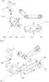
- the fingers can be realized as shown in figures 14 and 15 , wherein exploded views of an embodiment of one of the fingers of the device according to the invention are shown.
- the finger can be realized by using three components (701, 702, 703) hinged to each other in axes corresponding to the relative axis of rotation of the phalanges.
- These components preferably realized in aluminum, steel, titanium or in plastic material provided with suitable structural strength, can be encased by applying surfaces of several softer materials (7011, 7012, 7013, 7014, 7021, 7022, 7023, 7024, 7031), such as for example silicone or rubber, so that the resemblance of the hand according to the invention to a human hand in terms of functionalities is improved, as for example a higher friction between fingers and the grasped objects and a better adaptation to their shape and dimensions.
- the clamping screws of the encasing elements present a seat where the springs are fitted, so by screwing or unscrewing such screws it is possible to carry out a precise pre-loading of the springs.
- the encasing elements can be also used to contain sensors useful for the prosthesis functioning or to provide a feedback to the user.
- the device can be realized by using sun gears with different diameter inside the same differential stage.
- the use of sun gears with different diameter in a bevel gear differential stage is shown schematically in figure 10 .
- sun gears with different diameters means the need to incline the axes of the spider gears, but allows to distribute the torque differently between the sun gears and thus between the fingers by them actuated, thus increasing the degree of resemblance to the human hand.
- the different diameters of the sun gears can be configured so that the torque transmitted to the four aligned fingers is approximately subdivided according to what indicated in the following: 25% for fingers 2 and 4, 35% for finger 3, 15% for finger 5.
- FIG 8 Another variant of the mechanism is shown in figure 8 , wherein the underactuated hand according to the invention is realized with the axis of rotation of the sun gears (05, 06) of the stage zero orthogonal to the direction of the four aligned fingers when in extended position.
- This direction of the axis of rotation of the sun gears (05, 06) of the stage zero implies some constructive advantages: firstly, it allows to obtain coupling between the sun gear (05) of the stage zero and the planet carrier (14) of the stage 1 by means of spur gears, rather than of conical gears or face gears, with all the technical simplifications deriving therefrom (smaller dimensions, higher precision and components constructive and realization simplicity). Moreover, this arrangement of the differential stage zero allows to carry out the coupling between motor and differential 0 by using a worm gear reducer, difficult to obtain in other configurations due to dimensional restrictions.
- the kinematic scheme shown is an example and does not limit the aims of the invention. Is it to be specified that, as a way of example, the dimension of the limb can be modified by changing, according to need, the gears module, the number of teeth of the pulleys or the length of the toothed belts, while the speed ratio between the thumb and the other fingers (in the absence of external loads, since under load the configuration assumed by the hand is determined by the forces exchanged with the grasped object) can be varied by changing the transmission ratio between the first and the second bevel gear differential stage (gears 05 and 14) or between the first and the fifth ones (gears 06 and 44). The speed ratio between adduction and flexion of the thumb can be instead modified by changing the transmission ratio between the gear 45 and the gear perpendicular thereto (47) .
- knots with the indication "1" refer to an actively controllable degree of freedom.
- the knots which report the indication "1+1” refer to the knots in which a degree of freedom is actively controllable (extension/flexion) while the other is passive, and can only adapt to the shape of the grasped object (adduction/abduction).
- the number of degrees of freedom of the underactuated anthropomorphic hand according to the invention can be increased, by adding another little phalanx to the thumb.
- the thumb would be than realized and actuated absolutely identically to what described for the other fingers.
Landscapes
- Engineering & Computer Science (AREA)
- Robotics (AREA)
- Mechanical Engineering (AREA)
- Manipulator (AREA)
- Prostheses (AREA)
- Control And Other Processes For Unpacking Of Materials (AREA)
- Sampling And Sample Adjustment (AREA)
Claims (13)
- Anthropomorphe Roboterhand, umfassend:- eine Handfläche (00) und einen Metacarpus (10), die derart konfiguriert sind, dass sie sich in Bezug auf die Handfläche um eine Drehachse (180) drehen;- vier Finger, die im wesentlichen ausgerichtet und mit der Handfläche verbunden sind, und einen Finger, der ihnen gegenüberliegend ist, wobei jeder der ausgerichteten Finger mindestens eine proximale Phalanx (21, 31, 41, 51), eine mittlere Phalanx (22, 32, 42, 52) und eine distale Phalanx (23, 33, 43, 53) umfasst und der gegenüberliegende Finger eine proximale Phalanx (11) und eine distale Phalanx (13) umfasst, wobei die proximalen Phalangen (21, 31, 41, 51) von jedem der ausgerichteten Finger in den jeweiligen Drehachsen (240, 340, 440, 540) an der Handfläche (00) angelenkt sind und die proximale Phalanx (11) des gegenüberliegenden Fingers in einer jeweiligen Drehachse (140) an dem Metacarpus (10) angelenkt ist;- einen Motor (100)- mehrere Kegelraddifferentialstufen, die eine Bewegung von dem Motor (100) auf die ausgerichteten Finger und auf den gegenüberliegenden Finger übertragen;dadurch gekennzeichnet, dass
der Motor (100) derart konfiguriert ist, um nur den Planetenträger einer ersten Differenzialstufe direkt anzutreiben;
wobei die mehreren Differentialstufen umfassen eine erste Differentialstufe, deren Planetenträger (04) von dem Motor (100) bewegt wird und deren Sonnenräder (05, 06) die Planetenträger einer zweiten (14) und einer fünften (44) Differentialstufe bewegen,
wobei die Sonnenräder (15, 16) der zweiten Differenzialstufe einstückig zu den Planetenträgern (24, 34) einer dritten und einer vierten Differenzialstufe sind;
wobei die Sonnenräder (26, 25, 36, 35) der dritten und vierten Differenzialstufe derart konfiguriert sind, dass sie jeweils mit vier Zahnrädern (210, 310, 410, 510) in Eingriff stehen, deren Achsen mit den jeweiligen Drehachsen (240, 340, 440, 540) zwischen den proximalen Phalangen (21, 31, 41, 51) der ausgerichteten Finger und der Handfläche (00); zusammenfallen;
und wobei die Sonnenräder (45, 46) der fünften Differenzialstufe derart konfiguriert sind, dass sie jeweils den Metacarpus (10) und ein Zahnrad (110) drehen, wobei die Achse mit der jeweiligen Drehachse (140) zwischen der proximalen Phalanx (11) des gegenüberliegenden Fingers und des Metacarpus (10) zusammenfält. - Anthropomorphe Roboterhand nach Anspruch 1, dadurch gekennzeichnet, dass- die Differentialstufen sind Kegelraddifferentiale;- die Drehachse der Sonnenräder (05, 06) der von dem Motor (100) bewegten Differenzialstufe ist parallel zu der Richtung, die die vier ausgerichteten Finger in ausgefahrener Position einnehmen;- die Kopplung zwischen dem Sonnenrad (05) der ersten Stufe und dem Planetenträger (14) der zweiten Stufe wird mittels Stirnrädern erreicht;- die Kopplung zwischen Motor und Planetenträger des Differentials der ersten Stufe erfolgt über ein Schneckengetriebe.
- Anthropomorphe Roboterhand nach Anspruch 1 oder 2, dadurch gekennzeichnet, dass innerhalb mindestens einer der Kegelraddifferentialstufen weisen die Sonnenräder unterschiedliche Durchmesser auf, so dass das Drehmoment nicht gleichmäßig auf die ausgerichteten Finger verteilt wird.
- Anthropomorphe Roboterhand nach Anspruch 3, dadurch gekennzeichnet, dass die Durchmesser der Sonnenräder derart konfiguriert sind, dass das auf die vier ausgerichteten Finger übertragene Drehmoment wie folgt unterteilt ist: 25% für Zeigefinger und Ringfinger, 35% für Mittelfinger, 15% für kleinen Finger.
- Anthropomorphe Roboterhand nach einem der vorhergehenden Ansprüche, dadurch gekennzeichnet, dass die Drehachsen der Planetenträger (24, 34) der dritten und vierten Stufe geneigt zu den Wellen der Sonnenräder (16, 15) der zweiten Stufe montiert werden können, durch Zwischenlegen von Kardan-Gelenken (161, 151) auf entsprechenden Verbindungswellen, die die Übertragung der Rotation zwischen zueinander geneigten Wellen ermöglichen.
- Anthropomorphe Roboterhand gemäß einem der vorhergehenden Ansprüche, dadurch gekennzeichnet, dass jeder der ausgerichteten Finger einen ersten (210, 310, 410, 510), einen zweiten (220, 320, 420, 520) und einen dritten (230, 330, 430, 530) gezahnte Riemenscheibe mit Drehachsen umfasst, die jeweils mit der relativen Drehachse zwischen den proximalen Phalangen (21, 31, 41, 51) und der Handfläche (00) zwischen den mittleren Phalangen (22, 32, 42, 52) und die proximalen Phalangen (21, 31, 41, 51) und zwischen den distalen Phalangen (23, 33, 43, 53) und den mittleren Phalangen (22, 32, 42, 52) zusammenfällt, wobei die ersten (210, 310, 410, 510) und zweite (220, 320, 420, 520) gezahnte Riemenscheiben sind in Bezug auf ihre relativen Drehachsen im Leerlauf und über einen Zahnriemen (211, 311, 411, 511) miteinander verbunden, wobei die dritten gezahnte Riemenscheiben (230, 330, 430, 530) jeweils einstückig zu ihrer jeweiligen distalen Phalanx (23, 33, 43, 53) sind und mittels Zahnriemen (221, 321, 421, 521) zu den zweiten Zahnrädern (220, 320, 420, 520) verbunden sind.
- Anthropomorphe Roboterhand nach Anspruch 6, dadurch gekennzeichnet, dass die ersten (210, 310, 410, 510) gezahnten Riemenscheiben jedes Fingers zweckmäßigerweise aus einem Zahnrad bestehen, das in eine gezahnte Riemenscheibe integriert ist.
- Anthropomorphe Roboterhand nach Anspruch 6 oder 7, dadurch gekennzeichnet, dass die Gestalt der Phalangen (11, 12, 21, 22, 23, 31, 32, 33, 41, 42, 43, 51, 52, 53) des Metacarpus (10) und der Handfläche (00) derart ist, dass die zulässige Drehung um alle jeweiligen Drehachsen auf Werte begrenzt ist, die den physiologischen Werten der jeweiligen Komponenten der menschlichen Hand ähnlich sind, und vorzugsweise zwischen 90° und 110° für die proximale Phalanx, zwischen 90° und 135° für die mittlere Phalanx und zwischen 85° und 90° für die distale Phalanx sind.
- Anthropomorphe Roboterhand nach den Ansprüchen 6, 7 oder 8, dadurch gekennzeichnet, dass die Biegung der proximalen Phalanx (11) des gegenüberliegenden Fingers etwa 70°, die Biegung der distalen Phalanx (13) des gegenüberliegenden Fingers etwa 75° betragen kann, und wobei der Metacarpus (10) um etwa 90° drehen kann.
- Anthropomorphe Roboterhand nach Anspruch 8 oder 9, dadurch gekennzeichnet, dass mindestens ein Teil der mechanischen Grenzen, die die Drehwinkel zwischen den verschiedenen Komponenten definieren, unter Verwendung von elastischem Material realisiert werden.
- Anthropomorphe Roboterhand nach einem der vorhergehenden Ansprüche, dadurch gekennzeichnet, dass bei allen relativen Drehachsen zwischen den Phalangen (140, 160, 240, 250, 260, 340, 350, 360, 440, 450, 460, 540 550, 560) und an der Drehachse (180) des Metacarpus (10) Federn vorgesehen sind, die ein elastisches Drehmoment zwischen den verschiedenen Gelenkelementen, vorzugsweise in Richtung des Handschließens ausüben.
- Anthropomorphe Roboterhand nach einem der vorhergehenden Ansprüche, ferner umfassend eine Bremse (141, 241, 341, 441, 551), die unabhängig in Übereinstimmung mit jeder der relativen Rotationsachsen zwischen den proximalen Phalangen und der Handfläche und zwischen dem Metacarpus und der Handfläche betätigt werden können.
- Anthropomorphe Roboterhand nach einem der vorhergehenden Ansprüche, dadurch gekennzeichnet, dass zwischen den proximalen Phalangen und der Welle, an der sie angelenkt sind, ein Zylinder angeordnet ist, der koaxial zu der Welle (240) in elastischem Material gefertigt ist, was eine bestimmte Grad der Adduktion/Abduktion der Finger gestattet.
Priority Applications (1)
| Application Number | Priority Date | Filing Date | Title |
|---|---|---|---|
| PL17826277T PL3548228T3 (pl) | 2016-11-29 | 2017-11-29 | Niedostatecznie pobudzona ręka robotyczna |
Applications Claiming Priority (2)
| Application Number | Priority Date | Filing Date | Title |
|---|---|---|---|
| IT102016000120646A IT201600120646A1 (it) | 2016-11-29 | 2016-11-29 | Mano robotica sottoattuata |
| PCT/IB2017/057477 WO2018100500A1 (en) | 2016-11-29 | 2017-11-29 | Underactuated robotic hand |
Publications (2)
| Publication Number | Publication Date |
|---|---|
| EP3548228A1 EP3548228A1 (de) | 2019-10-09 |
| EP3548228B1 true EP3548228B1 (de) | 2021-03-31 |
Family
ID=58347818
Family Applications (1)
| Application Number | Title | Priority Date | Filing Date |
|---|---|---|---|
| EP17826277.0A Active EP3548228B1 (de) | 2016-11-29 | 2017-11-29 | Unterbetätigte roboterhand |
Country Status (7)
| Country | Link |
|---|---|
| US (1) | US11597099B2 (de) |
| EP (1) | EP3548228B1 (de) |
| CN (1) | CN110520256B (de) |
| ES (1) | ES2877214T3 (de) |
| IT (1) | IT201600120646A1 (de) |
| PL (1) | PL3548228T3 (de) |
| WO (1) | WO2018100500A1 (de) |
Families Citing this family (31)
| Publication number | Priority date | Publication date | Assignee | Title |
|---|---|---|---|---|
| US10973660B2 (en) * | 2017-12-15 | 2021-04-13 | Touch Bionics Limited | Powered prosthetic thumb |
| PL426475A1 (pl) * | 2018-07-27 | 2020-02-10 | 3D Gence Spółka Z Ograniczoną Odpowiedzialnością | Chwytak ramienia robota |
| CN108908391A (zh) * | 2018-08-14 | 2018-11-30 | 东南大学 | 一种基于差速器结构的仿生机械手 |
| WO2020105504A1 (ja) * | 2018-11-20 | 2020-05-28 | 株式会社メルティンMmi | ロボットハンド装置 |
| CN113853181A (zh) | 2019-04-10 | 2021-12-28 | 塔驰仿生有限公司 | 具有铰接连杆的假肢手指 |
| CN110151494B (zh) * | 2019-06-24 | 2024-01-23 | 深圳睿瀚医疗科技有限公司 | 多驱动模块化外骨骼机构 |
| US20220288771A1 (en) * | 2019-07-23 | 2022-09-15 | Auckland Uniservices Limited | An underactuated soft robotic grasping device |
| US12527672B2 (en) | 2019-09-18 | 2026-01-20 | Touch Bionics Limited | Prosthetic digits and actuators |
| CN110640774B (zh) * | 2019-10-22 | 2021-10-29 | 上海理工大学 | 一种六自由度五指机械手 |
| USD1030906S1 (en) * | 2019-10-22 | 2024-06-11 | Smartivity Labs Pvt. Ltd. | Hand toy |
| US11931270B2 (en) | 2019-11-15 | 2024-03-19 | Touch Bionics Limited | Prosthetic digit actuator |
| CN110948516B (zh) * | 2019-12-13 | 2024-08-23 | 北京理工大学 | 一种欠驱动仿生手腕装置 |
| CN111152254B (zh) * | 2020-01-09 | 2021-04-20 | 江南大学 | 一种软轴传动的刚柔耦合手指四指欠驱动机械手 |
| JP2021159999A (ja) * | 2020-03-30 | 2021-10-11 | 国立研究開発法人産業技術総合研究所 | 複数の指を有するロボットハンドの駆動機構 |
| CN111452082B (zh) * | 2020-04-30 | 2024-09-13 | 天津大学 | 一种带有可分岔手掌和同轴转动手腕的欠驱动灵巧手 |
| CN112077868B (zh) * | 2020-09-19 | 2024-12-13 | 重庆大学 | 具有机械自锁功能的单电机欠驱动机器人末端执行器 |
| EP4197717A4 (de) | 2020-10-22 | 2024-03-13 | Samsung Electronics Co., Ltd. | Greifvorrichtung und robotervorrichtung damit |
| KR20220131089A (ko) * | 2021-03-19 | 2022-09-27 | 현대자동차주식회사 | 로봇용 관절 구조체 및 그 구조체를 포함하는 로봇 |
| US12017346B2 (en) * | 2021-03-24 | 2024-06-25 | City University Of Hong Kong | Articulated actuated finger with self-locking joints |
| CN112976035B (zh) * | 2021-05-21 | 2021-08-10 | 季华实验室 | 一种灵巧手指和机械夹爪 |
| CN113211477B (zh) * | 2021-06-10 | 2022-05-06 | 哈尔滨工业大学 | 具有耦合自适应运动特性的欠驱动手指 |
| JP7610909B2 (ja) * | 2021-08-24 | 2025-01-09 | ダブル技研株式会社 | 人間型ハンド |
| CN114536381B (zh) * | 2022-04-26 | 2022-09-06 | 中国科学院自动化研究所 | 仿人五指灵巧手 |
| CN114536380B (zh) * | 2022-04-26 | 2022-09-06 | 中国科学院自动化研究所 | 五自由度全驱动仿人大拇指和仿人灵巧手 |
| IT202200012392A1 (it) * | 2022-06-13 | 2023-12-13 | Bionit Labs S R L | Mano robotica sottoattuata |
| CN115319777B (zh) * | 2022-07-26 | 2024-07-16 | 华中科技大学 | 一种基于欠驱动差速器的工业夹持器 |
| TWI854394B (zh) * | 2022-12-13 | 2024-09-01 | 依思 張 | 人形機械手之指部關節傳動構造 |
| CN116587249A (zh) * | 2023-05-31 | 2023-08-15 | 华中科技大学 | 基于行星齿轮差速机构的欠驱动牵引装置及手部外骨骼 |
| CN116652992B (zh) * | 2023-07-28 | 2024-09-10 | 哈尔滨工业大学 | 一种机械拇指对掌关节、机械拇指及机械手 |
| CN118832617A (zh) * | 2024-08-02 | 2024-10-25 | 青岛征和工业股份有限公司 | 一种带传动多自由度机械手指及机械手 |
| US12539621B1 (en) | 2025-01-17 | 2026-02-03 | Humanoid Robot (Shanghai) Co., Ltd. | Biomimetic dexterous fingers and biomimetic robots |
Family Cites Families (17)
| Publication number | Priority date | Publication date | Assignee | Title |
|---|---|---|---|---|
| CN87103848A (zh) * | 1987-05-24 | 1988-12-14 | 浙江大学 | 自适应机械手 |
| US5062673A (en) * | 1988-12-28 | 1991-11-05 | Kabushiki Kaisha Toyota Chuo Kenkyusho | Articulated hand |
| US5447403A (en) * | 1990-01-05 | 1995-09-05 | Engler, Jr.; Charles D. | Dexterous programmable robot and control system |
| KR100451412B1 (ko) * | 2001-11-09 | 2004-10-06 | 한국과학기술연구원 | 다지 로봇 핸드 |
| CN1289269C (zh) * | 2002-03-15 | 2006-12-13 | 清华大学 | 自适应欠驱动机械手指装置 |
| CN100439048C (zh) * | 2007-01-26 | 2008-12-03 | 清华大学 | 机器人拟人手欠驱动多指装置 |
| US8720964B2 (en) * | 2009-01-20 | 2014-05-13 | Polyvalor, Limited Partnership | Self-adaptive mechanical finger and method |
| CN101491900B (zh) * | 2009-03-02 | 2010-09-15 | 清华大学 | 拟人机器人手手指侧摆装置 |
| US8936289B1 (en) * | 2010-03-15 | 2015-01-20 | Telefactor Robotics LLC | Robotic finger assemblies |
| WO2011118646A1 (ja) * | 2010-03-24 | 2011-09-29 | 株式会社安川電機 | ロボットハンド及びロボット装置 |
| CN102284957A (zh) * | 2011-07-26 | 2011-12-21 | 清华大学 | 差动锥齿轮齿条式复合欠驱动机器人手指装置 |
| CN102363302B (zh) * | 2011-10-25 | 2013-09-18 | 杭州电子科技大学 | 一种单电机驱动的仿人灵巧手装置 |
| CN103213137B (zh) * | 2013-04-16 | 2016-05-25 | 清华大学 | 凸轮式快速抓取欠驱动机器人手装置 |
| GB2528049A (en) * | 2014-07-07 | 2016-01-13 | Univ Cape Town | Underactuated prosthetic hand |
| US9492928B2 (en) * | 2014-11-05 | 2016-11-15 | Toyota Motor Engineering & Manufacturing North America, Inc. | Interconnected phalanges for robotic gripping |
| CN204366983U (zh) * | 2015-01-04 | 2015-06-03 | 山东科技大学 | 一种基于模块化设计的欠驱动灵巧手 |
| US9744677B2 (en) * | 2015-11-05 | 2017-08-29 | Irobot Corporation | Robotic fingers and end effectors including same |
-
2016
- 2016-11-29 IT IT102016000120646A patent/IT201600120646A1/it unknown
-
2017
- 2017-11-29 CN CN201780071331.6A patent/CN110520256B/zh active Active
- 2017-11-29 WO PCT/IB2017/057477 patent/WO2018100500A1/en not_active Ceased
- 2017-11-29 ES ES17826277T patent/ES2877214T3/es active Active
- 2017-11-29 US US16/341,730 patent/US11597099B2/en active Active
- 2017-11-29 EP EP17826277.0A patent/EP3548228B1/de active Active
- 2017-11-29 PL PL17826277T patent/PL3548228T3/pl unknown
Non-Patent Citations (1)
| Title |
|---|
| None * |
Also Published As
| Publication number | Publication date |
|---|---|
| WO2018100500A1 (en) | 2018-06-07 |
| EP3548228A1 (de) | 2019-10-09 |
| ES2877214T3 (es) | 2021-11-16 |
| CN110520256B (zh) | 2022-08-19 |
| IT201600120646A1 (it) | 2018-05-29 |
| CN110520256A (zh) | 2019-11-29 |
| US11597099B2 (en) | 2023-03-07 |
| PL3548228T3 (pl) | 2021-10-25 |
| US20200047351A1 (en) | 2020-02-13 |
Similar Documents
| Publication | Publication Date | Title |
|---|---|---|
| US11597099B2 (en) | Underactuated robotic hand | |
| Cempini et al. | A powered finger–thumb wearable hand exoskeleton with self-aligning joint axes | |
| Controzzi et al. | Design of artificial hands: A review | |
| Massa et al. | Design and development of an underactuated prosthetic hand | |
| EP2178680B1 (de) | Tragbares mechatronisches gerät | |
| CN103830025A (zh) | 具有力位及触觉感知功能的两自由度模块化假手拇指 | |
| US11246787B2 (en) | Bi-directional underactuated exoskeleton | |
| EP2861387B1 (de) | Verfahren zum betreiben und gerät zur mensch-mehrfach gelenkeinrichtung interaktion | |
| EP4536446B1 (de) | Unterbetätigte roboterhand | |
| Vulliez et al. | Focus on the mechatronics design of a new dexterous robotic hand for inside hand manipulation | |
| Kurita et al. | Human-sized anthropomorphic robot hand with detachable mechanism at the wrist | |
| Rahman et al. | A novel variable impedance compact compliant ankle robot for overground gait rehabilitation and assistance | |
| Rahman | A novel variable impedance compact compliant series elastic actuator for human-friendly soft robotics applications | |
| Zhang et al. | Mechanical design and control method for sea and VSA-based exoskeleton devices for elbow joint rehabilitation | |
| Koganezawa et al. | Antagonistic control of multi-DOF joint by using the actuator with non-linear elasticity | |
| Koganezawa et al. | Artificial hand with stiffness adjuster | |
| Chay et al. | Upper extremity robotics exoskeleton: Application, structure and actuation | |
| Mobedi et al. | A soft assistive device for elbow effort-compensation | |
| Ma et al. | Tendon transmission efficiency of a two-finger haptic glove | |
| Lau et al. | The development of a low cost pneumatic air muscle actuated anthropomorphic robotic hand | |
| Scarcia | Design and control of robotic hands | |
| Rahman | A novel variable impedance compact compliant series elastic actuator: analysis of design, dynamics, materials and manufacturing | |
| Poddar et al. | A cable-actuated prosthetic emulator for transradial amputees | |
| EP3860810B1 (de) | Exoskelett zur unterstützung von polyartikulären gelenken | |
| Poddar et al. | A lightweight transradial prosthetic emulator for optimizing prosthetic wrist design |
Legal Events
| Date | Code | Title | Description |
|---|---|---|---|
| STAA | Information on the status of an ep patent application or granted ep patent |
Free format text: STATUS: UNKNOWN |
|
| STAA | Information on the status of an ep patent application or granted ep patent |
Free format text: STATUS: THE INTERNATIONAL PUBLICATION HAS BEEN MADE |
|
| PUAI | Public reference made under article 153(3) epc to a published international application that has entered the european phase |
Free format text: ORIGINAL CODE: 0009012 |
|
| STAA | Information on the status of an ep patent application or granted ep patent |
Free format text: STATUS: REQUEST FOR EXAMINATION WAS MADE |
|
| 17P | Request for examination filed |
Effective date: 20190510 |
|
| AK | Designated contracting states |
Kind code of ref document: A1 Designated state(s): AL AT BE BG CH CY CZ DE DK EE ES FI FR GB GR HR HU IE IS IT LI LT LU LV MC MK MT NL NO PL PT RO RS SE SI SK SM TR |
|
| AX | Request for extension of the european patent |
Extension state: BA ME |
|
| DAV | Request for validation of the european patent (deleted) | ||
| DAX | Request for extension of the european patent (deleted) | ||
| GRAP | Despatch of communication of intention to grant a patent |
Free format text: ORIGINAL CODE: EPIDOSNIGR1 |
|
| STAA | Information on the status of an ep patent application or granted ep patent |
Free format text: STATUS: GRANT OF PATENT IS INTENDED |
|
| INTG | Intention to grant announced |
Effective date: 20201022 |
|
| RIN1 | Information on inventor provided before grant (corrected) |
Inventor name: ZAPPATORE, GIOVANNI ANTONIO |
|
| GRAS | Grant fee paid |
Free format text: ORIGINAL CODE: EPIDOSNIGR3 |
|
| GRAA | (expected) grant |
Free format text: ORIGINAL CODE: 0009210 |
|
| STAA | Information on the status of an ep patent application or granted ep patent |
Free format text: STATUS: THE PATENT HAS BEEN GRANTED |
|
| AK | Designated contracting states |
Kind code of ref document: B1 Designated state(s): AL AT BE BG CH CY CZ DE DK EE ES FI FR GB GR HR HU IE IS IT LI LT LU LV MC MK MT NL NO PL PT RO RS SE SI SK SM TR |
|
| REG | Reference to a national code |
Ref country code: GB Ref legal event code: FG4D Ref country code: CH Ref legal event code: EP |
|
| REG | Reference to a national code |
Ref country code: DE Ref legal event code: R096 Ref document number: 602017035887 Country of ref document: DE Ref country code: AT Ref legal event code: REF Ref document number: 1376420 Country of ref document: AT Kind code of ref document: T Effective date: 20210415 |
|
| REG | Reference to a national code |
Ref country code: IE Ref legal event code: FG4D |
|
| REG | Reference to a national code |
Ref country code: NL Ref legal event code: FP |
|
| REG | Reference to a national code |
Ref country code: SE Ref legal event code: TRGR |
|
| REG | Reference to a national code |
Ref country code: LT Ref legal event code: MG9D |
|
| PG25 | Lapsed in a contracting state [announced via postgrant information from national office to epo] |
Ref country code: NO Free format text: LAPSE BECAUSE OF FAILURE TO SUBMIT A TRANSLATION OF THE DESCRIPTION OR TO PAY THE FEE WITHIN THE PRESCRIBED TIME-LIMIT Effective date: 20210630 Ref country code: FI Free format text: LAPSE BECAUSE OF FAILURE TO SUBMIT A TRANSLATION OF THE DESCRIPTION OR TO PAY THE FEE WITHIN THE PRESCRIBED TIME-LIMIT Effective date: 20210331 Ref country code: HR Free format text: LAPSE BECAUSE OF FAILURE TO SUBMIT A TRANSLATION OF THE DESCRIPTION OR TO PAY THE FEE WITHIN THE PRESCRIBED TIME-LIMIT Effective date: 20210331 Ref country code: BG Free format text: LAPSE BECAUSE OF FAILURE TO SUBMIT A TRANSLATION OF THE DESCRIPTION OR TO PAY THE FEE WITHIN THE PRESCRIBED TIME-LIMIT Effective date: 20210630 |
|
| PG25 | Lapsed in a contracting state [announced via postgrant information from national office to epo] |
Ref country code: RS Free format text: LAPSE BECAUSE OF FAILURE TO SUBMIT A TRANSLATION OF THE DESCRIPTION OR TO PAY THE FEE WITHIN THE PRESCRIBED TIME-LIMIT Effective date: 20210331 Ref country code: LV Free format text: LAPSE BECAUSE OF FAILURE TO SUBMIT A TRANSLATION OF THE DESCRIPTION OR TO PAY THE FEE WITHIN THE PRESCRIBED TIME-LIMIT Effective date: 20210331 |
|
| PG25 | Lapsed in a contracting state [announced via postgrant information from national office to epo] |
Ref country code: CZ Free format text: LAPSE BECAUSE OF FAILURE TO SUBMIT A TRANSLATION OF THE DESCRIPTION OR TO PAY THE FEE WITHIN THE PRESCRIBED TIME-LIMIT Effective date: 20210331 Ref country code: EE Free format text: LAPSE BECAUSE OF FAILURE TO SUBMIT A TRANSLATION OF THE DESCRIPTION OR TO PAY THE FEE WITHIN THE PRESCRIBED TIME-LIMIT Effective date: 20210331 Ref country code: LT Free format text: LAPSE BECAUSE OF FAILURE TO SUBMIT A TRANSLATION OF THE DESCRIPTION OR TO PAY THE FEE WITHIN THE PRESCRIBED TIME-LIMIT Effective date: 20210331 Ref country code: SM Free format text: LAPSE BECAUSE OF FAILURE TO SUBMIT A TRANSLATION OF THE DESCRIPTION OR TO PAY THE FEE WITHIN THE PRESCRIBED TIME-LIMIT Effective date: 20210331 |
|
| REG | Reference to a national code |
Ref country code: ES Ref legal event code: FG2A Ref document number: 2877214 Country of ref document: ES Kind code of ref document: T3 Effective date: 20211116 |
|
| PG25 | Lapsed in a contracting state [announced via postgrant information from national office to epo] |
Ref country code: PT Free format text: LAPSE BECAUSE OF FAILURE TO SUBMIT A TRANSLATION OF THE DESCRIPTION OR TO PAY THE FEE WITHIN THE PRESCRIBED TIME-LIMIT Effective date: 20210802 Ref country code: RO Free format text: LAPSE BECAUSE OF FAILURE TO SUBMIT A TRANSLATION OF THE DESCRIPTION OR TO PAY THE FEE WITHIN THE PRESCRIBED TIME-LIMIT Effective date: 20210331 Ref country code: SK Free format text: LAPSE BECAUSE OF FAILURE TO SUBMIT A TRANSLATION OF THE DESCRIPTION OR TO PAY THE FEE WITHIN THE PRESCRIBED TIME-LIMIT Effective date: 20210331 |
|
| REG | Reference to a national code |
Ref country code: DE Ref legal event code: R097 Ref document number: 602017035887 Country of ref document: DE |
|
| PG25 | Lapsed in a contracting state [announced via postgrant information from national office to epo] |
Ref country code: DK Free format text: LAPSE BECAUSE OF FAILURE TO SUBMIT A TRANSLATION OF THE DESCRIPTION OR TO PAY THE FEE WITHIN THE PRESCRIBED TIME-LIMIT Effective date: 20210331 Ref country code: AL Free format text: LAPSE BECAUSE OF FAILURE TO SUBMIT A TRANSLATION OF THE DESCRIPTION OR TO PAY THE FEE WITHIN THE PRESCRIBED TIME-LIMIT Effective date: 20210331 |
|
| PLBE | No opposition filed within time limit |
Free format text: ORIGINAL CODE: 0009261 |
|
| STAA | Information on the status of an ep patent application or granted ep patent |
Free format text: STATUS: NO OPPOSITION FILED WITHIN TIME LIMIT |
|
| 26N | No opposition filed |
Effective date: 20220104 |
|
| PG25 | Lapsed in a contracting state [announced via postgrant information from national office to epo] |
Ref country code: IT Free format text: LAPSE BECAUSE OF FAILURE TO SUBMIT A TRANSLATION OF THE DESCRIPTION OR TO PAY THE FEE WITHIN THE PRESCRIBED TIME-LIMIT Effective date: 20210331 |
|
| REG | Reference to a national code |
Ref country code: AT Ref legal event code: UEP Ref document number: 1376420 Country of ref document: AT Kind code of ref document: T Effective date: 20210331 |
|
| PG25 | Lapsed in a contracting state [announced via postgrant information from national office to epo] |
Ref country code: CY Free format text: LAPSE BECAUSE OF FAILURE TO SUBMIT A TRANSLATION OF THE DESCRIPTION OR TO PAY THE FEE WITHIN THE PRESCRIBED TIME-LIMIT Effective date: 20210331 |
|
| PG25 | Lapsed in a contracting state [announced via postgrant information from national office to epo] |
Ref country code: HU Free format text: LAPSE BECAUSE OF FAILURE TO SUBMIT A TRANSLATION OF THE DESCRIPTION OR TO PAY THE FEE WITHIN THE PRESCRIBED TIME-LIMIT; INVALID AB INITIO Effective date: 20171129 Ref country code: GR Free format text: LAPSE BECAUSE OF FAILURE TO SUBMIT A TRANSLATION OF THE DESCRIPTION OR TO PAY THE FEE WITHIN THE PRESCRIBED TIME-LIMIT Effective date: 20210331 |
|
| PGFP | Annual fee paid to national office [announced via postgrant information from national office to epo] |
Ref country code: LU Payment date: 20231114 Year of fee payment: 7 |
|
| PGFP | Annual fee paid to national office [announced via postgrant information from national office to epo] |
Ref country code: MC Payment date: 20231115 Year of fee payment: 7 |
|
| PG25 | Lapsed in a contracting state [announced via postgrant information from national office to epo] |
Ref country code: MK Free format text: LAPSE BECAUSE OF FAILURE TO SUBMIT A TRANSLATION OF THE DESCRIPTION OR TO PAY THE FEE WITHIN THE PRESCRIBED TIME-LIMIT Effective date: 20210331 |
|
| PG25 | Lapsed in a contracting state [announced via postgrant information from national office to epo] |
Ref country code: MT Free format text: LAPSE BECAUSE OF FAILURE TO SUBMIT A TRANSLATION OF THE DESCRIPTION OR TO PAY THE FEE WITHIN THE PRESCRIBED TIME-LIMIT Effective date: 20210331 |
|
| PG25 | Lapsed in a contracting state [announced via postgrant information from national office to epo] |
Ref country code: MC Free format text: LAPSE BECAUSE OF NON-PAYMENT OF DUE FEES Effective date: 20241202 |
|
| PG25 | Lapsed in a contracting state [announced via postgrant information from national office to epo] |
Ref country code: LU Free format text: LAPSE BECAUSE OF NON-PAYMENT OF DUE FEES Effective date: 20241129 |
|
| PGFP | Annual fee paid to national office [announced via postgrant information from national office to epo] |
Ref country code: PL Payment date: 20250929 Year of fee payment: 9 Ref country code: NL Payment date: 20250916 Year of fee payment: 9 |
|
| PGFP | Annual fee paid to national office [announced via postgrant information from national office to epo] |
Ref country code: BE Payment date: 20250916 Year of fee payment: 9 Ref country code: GB Payment date: 20250915 Year of fee payment: 9 |
|
| PGFP | Annual fee paid to national office [announced via postgrant information from national office to epo] |
Ref country code: FR Payment date: 20250915 Year of fee payment: 9 |
|
| PGFP | Annual fee paid to national office [announced via postgrant information from national office to epo] |
Ref country code: SE Payment date: 20250918 Year of fee payment: 9 |
|
| PGFP | Annual fee paid to national office [announced via postgrant information from national office to epo] |
Ref country code: IE Payment date: 20250915 Year of fee payment: 9 |
|
| PGFP | Annual fee paid to national office [announced via postgrant information from national office to epo] |
Ref country code: IS Payment date: 20250915 Year of fee payment: 9 |
|
| REG | Reference to a national code |
Ref country code: CH Ref legal event code: U11 Free format text: ST27 STATUS EVENT CODE: U-0-0-U10-U11 (AS PROVIDED BY THE NATIONAL OFFICE) Effective date: 20251201 |
|
| PGFP | Annual fee paid to national office [announced via postgrant information from national office to epo] |
Ref country code: DE Payment date: 20250916 Year of fee payment: 9 |
|
| PGFP | Annual fee paid to national office [announced via postgrant information from national office to epo] |
Ref country code: AT Payment date: 20250916 Year of fee payment: 9 |
|
| PGFP | Annual fee paid to national office [announced via postgrant information from national office to epo] |
Ref country code: TR Payment date: 20251124 Year of fee payment: 9 |
|
| PGFP | Annual fee paid to national office [announced via postgrant information from national office to epo] |
Ref country code: CH Payment date: 20251201 Year of fee payment: 9 |
|
| PGFP | Annual fee paid to national office [announced via postgrant information from national office to epo] |
Ref country code: ES Payment date: 20251208 Year of fee payment: 9 |