EP3548194B1 - Ultrasonic lens cleaning system with foreign material detection - Google Patents
Ultrasonic lens cleaning system with foreign material detection Download PDFInfo
- Publication number
- EP3548194B1 EP3548194B1 EP17878085.4A EP17878085A EP3548194B1 EP 3548194 B1 EP3548194 B1 EP 3548194B1 EP 17878085 A EP17878085 A EP 17878085A EP 3548194 B1 EP3548194 B1 EP 3548194B1
- Authority
- EP
- European Patent Office
- Prior art keywords
- frequency
- lens
- cleaning
- measured
- resonant frequency
- Prior art date
- Legal status (The legal status is an assumption and is not a legal conclusion. Google has not performed a legal analysis and makes no representation as to the accuracy of the status listed.)
- Active
Links
- 238000004140 cleaning Methods 0.000 title claims description 176
- 238000001514 detection method Methods 0.000 title description 17
- 239000000463 material Substances 0.000 title description 5
- 230000004044 response Effects 0.000 claims description 78
- 239000000356 contaminant Substances 0.000 claims description 63
- 238000000034 method Methods 0.000 claims description 20
- 230000008859 change Effects 0.000 description 35
- XLYOFNOQVPJJNP-UHFFFAOYSA-N water Substances O XLYOFNOQVPJJNP-UHFFFAOYSA-N 0.000 description 34
- 230000006870 function Effects 0.000 description 25
- 230000003749 cleanliness Effects 0.000 description 15
- 230000005284 excitation Effects 0.000 description 12
- 230000003287 optical effect Effects 0.000 description 10
- 102100020760 Ferritin heavy chain Human genes 0.000 description 9
- 101001002987 Homo sapiens Ferritin heavy chain Proteins 0.000 description 9
- 230000008569 process Effects 0.000 description 4
- 238000012545 processing Methods 0.000 description 4
- 238000003384 imaging method Methods 0.000 description 3
- 230000000737 periodic effect Effects 0.000 description 3
- 230000035945 sensitivity Effects 0.000 description 3
- 125000006850 spacer group Chemical group 0.000 description 3
- 230000009471 action Effects 0.000 description 2
- 230000008901 benefit Effects 0.000 description 2
- 230000005540 biological transmission Effects 0.000 description 2
- 238000010586 diagram Methods 0.000 description 2
- 230000003534 oscillatory effect Effects 0.000 description 2
- 230000007704 transition Effects 0.000 description 2
- 238000004506 ultrasonic cleaning Methods 0.000 description 2
- 238000013459 approach Methods 0.000 description 1
- 239000003990 capacitor Substances 0.000 description 1
- 238000006243 chemical reaction Methods 0.000 description 1
- 230000000694 effects Effects 0.000 description 1
- 238000005265 energy consumption Methods 0.000 description 1
- 238000002847 impedance measurement Methods 0.000 description 1
- 238000009434 installation Methods 0.000 description 1
- 230000010358 mechanical oscillation Effects 0.000 description 1
- 238000012986 modification Methods 0.000 description 1
- 230000004048 modification Effects 0.000 description 1
- 238000012544 monitoring process Methods 0.000 description 1
- 230000000246 remedial effect Effects 0.000 description 1
- 238000007493 shaping process Methods 0.000 description 1
- 238000001228 spectrum Methods 0.000 description 1
- 239000007921 spray Substances 0.000 description 1
Images


Classifications
-
- G—PHYSICS
- G02—OPTICS
- G02B—OPTICAL ELEMENTS, SYSTEMS OR APPARATUS
- G02B27/00—Optical systems or apparatus not provided for by any of the groups G02B1/00 - G02B26/00, G02B30/00
- G02B27/0006—Optical systems or apparatus not provided for by any of the groups G02B1/00 - G02B26/00, G02B30/00 with means to keep optical surfaces clean, e.g. by preventing or removing dirt, stains, contamination, condensation
-
- G—PHYSICS
- G02—OPTICS
- G02B—OPTICAL ELEMENTS, SYSTEMS OR APPARATUS
- G02B13/00—Optical objectives specially designed for the purposes specified below
- G02B13/06—Panoramic objectives; So-called "sky lenses" including panoramic objectives having reflecting surfaces
-
- G—PHYSICS
- G02—OPTICS
- G02B—OPTICAL ELEMENTS, SYSTEMS OR APPARATUS
- G02B13/00—Optical objectives specially designed for the purposes specified below
- G02B13/16—Optical objectives specially designed for the purposes specified below for use in conjunction with image converters or intensifiers, or for use with projectors, e.g. objectives for projection TV
Definitions
- Camera systems are becoming more prevalent in automotive and other applications, such as vehicle cameras, security cameras, industrial automation systems, and in other applications and end-use systems. Operation of camera and lighting systems is facilitated by clean optical paths, which can be hindered by dirt, water or other debris, particularly in outdoor applications such as vehicle mounted camera systems, outdoor security camera systems, camera systems in industrial facilities, etc.
- camera or light source lenses may be subject to ambient weather conditions, dirt and debris, and other contaminants which can obstruct or interfere with optical transmission through the lens.
- Automatic lens cleaning systems LCDs
- Such systems may include air or water spray apparatus, or mechanical wipers to wash a lens surface.
- the invention is a driver for cleaning a lens as defined by claim 1, a lens cleaning system as defined by claim 6 and a method of operating a lens cleaning system as defined by claim 14.
- the invention includes a transducer mechanically coupled to a lens, a driver to provide an oscillating drive signal to the transducer, and a controller to control the drive signal frequency to vibrate the lens at frequencies in a range of interest.
- the controller determines a measured resonant frequency of the lens cleaning system in the frequency range of interest according to a transducer feedback signal, and selectively performs a lens cleaning operation if the measured resonant frequency differs from a baseline resonant frequency of the lens cleaning system for a clean lens.
- the frequency response of the lens cleaning system is used to evaluate the resonant frequencies of interest.
- the frequency response can be measured as an impedance response, admittance response or other frequency domain equivalent.
- Described examples provide lens cleaning solutions to detect the presence of contaminants on the lens to facilitate intelligent cleaning when appropriate and to selectively refrain from lens cleaning when little or no contaminants are present.
- cleaning levels such as transducer power level and/or cleaning duration are determined according to the amount of change from the baseline resonant frequency. This technique facilitates high power cleaning to remove large amounts of contaminants, while conserving power by using light cleaning to remove small detected amounts of contaminants, or to delay cleaning when the lens is determined to be clean.
- Couple or “couples” includes indirect or direct electrical or mechanical connection or combinations thereof. For example, if a first device couples to or is coupled with a second device, that connection may be through a direct electrical connection, or through an indirect electrical connection via one or more intervening devices and connections.
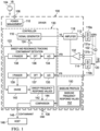
- FIG. 1 shows an ultrasonic lens cleaning system with a driver integrated circuit (IC) 100
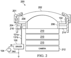
- FIG. 2 shows a camera lens assembly 200 including an ultrasonic lens cleaning system
- the lens assembly 200 includes a cylindrical or "ring" transducer 102 which is mechanically coupled to vibrate a lens 202.
- the transducer 102 is bonded to the lens 202.
- various techniques of this description can also be used in lighting systems or other optical systems, with or without a camera.
- the apparatus and techniques facilitate automatic detection of the presence or substantial absence of contaminants on the lens 202, and can be advantageously employed for selective lens cleaning when a threshold amount of contaminants are detected.
- a lens can be: a focusing element or other lens that implements optical shaping or other optical effect to aid camera imaging; or a lens cover or optical window that merely provides protection for further optical elements without performing any imaging functions.
- the lens 202 in one example is a "fisheye" lens having a curved outer surface as shown in FIG. 2 .
- a flat lens or a lens having a different profile can be used.
- the lens assembly in this example is mounted to a generally cylindrical housing 204 using a cylindrical cap fastener 201 and is sealed using an O-ring 208 extending between an edge of the lens 202 and the fastener 201 to prevent ingress of water or debris into the interior of the housing 204.
- the housing 204 can be mounted to a motor vehicle to operate as a lens cover for a rear backup camera, a forward-facing camera or a side-facing camera.
- the assembly 200 can be mounted to a building or a light pole, such as for security camera or lighting applications. In other examples, the assembly 200 can be used for interior security monitoring systems, such as within a commercial or residential building.
- a series of generally flat secondary lenses 210 are disposed within the inner surfaces of the spacer 206.
- the secondary lenses 210 and the fisheye lens 202 provide an optical path for imaging by a camera 212.
- the transducer 102 includes lead wires or terminals 131a and 131b that extend through an opening 216 in a base 214 of the housing 204 for connection with the driver IC 100.
- the lens 202 is mounted into the cylindrical housing 204 with a cylindrical inner spacer structure 206.
- the transducer 102 in this example is a cylindrical ring-shaped piezo-electric transducer disposed between the inner spacer 206 and the outer wall of the housing 204.
- the driver IC 100 includes a power input pin or pad 106 that receives input power from a power supply or power source 104, such as a battery providing a battery voltage signal VB with respect to a reference node 108 having a reference voltage (e.g., GND).
- the driver IC 100 includes a power management circuit 110 that receives the battery voltage signal VB and provides one or more supply voltages (not shown) to power the internal circuitry of the driver 100.
- the IC 100 includes an output with terminals 112 and 114 for connection to the lead wires 131a and 131b, respectively, of the transducer 102.
- the driver 100 output provides an oscillating drive signal VDRV at a non-zero frequency Ft to the transducer 102 to vibrate the lens 202.
- the controlled vibration of the lens 202 via excitation of the transducer 102 facilitates cleaning or removal of contaminants or debris from the outer surface of the lens 202.
- the transducer 102 is controlled by the driver 100 in different modes for assessing the cleanliness of the lens 202, and for selectively cleaning the lens 202 when appropriate according to a determined presence and amount of contaminants on the lens 202.
- the driver IC 100 determines one or more baseline profiles to identify resonant frequencies for the system having a clean lens 202 to facilitate subsequent determination of the presence or absence of contaminants on the lens 202.
- the driver IC 100 includes a controller or control circuit 130 with a signal generator 116.
- the controller 130 is a processor with an associated electronic memory.
- the controller 130 implements various cleaning, cleanliness detection, and optional calibration or baseline processing functions by controlling the oscillatory frequency Ft of the transducer 102.
- the controller 130 includes a sweep and resonance tracking, cleanliness detection circuit 122 with an output 124 that provides a desired frequency Ft to a signal generator circuit 116.
- the controller 130 is implemented in a processor, such as a DSP or other programmable digital circuit, which implements sweep and resonance tracking, cleanliness detection and calibration functions through execution of instructions stored in an associated memory to generate the frequency Ft as a digital value representing a desired frequency Ft of the drive signal VDRV.
- the signal generator 116 is a pulse width modulation (PWM) output of the processor that implements the controller 130.
- PWM pulse width modulation
- the signal generator circuit 116 provides an output signal VS that oscillates at a non-zero frequency Ft.
- the controller 130 includes an integral electronic memory, or is operatively connected to an external electronic memory 150 that stores program instructions implemented by the processor, and stores baseline profiles that include baseline frequency response values 152, such as baseline impedance values 152 that represent the frequency response of a lens cleaning system having a clean lens 202 as described further hereinbelow.
- the driver IC 100 further includes an amplifier 118 which amplifies the output signal VS to generate the oscillating drive signal VDRV.
- the controller 130 provides the desired frequency Ft of the drive signal VDRV, and thereby control the oscillatory frequency of the transducer 102 for cleaning the lens 202 and/or to implement baseline calibration and cleanliness detection functions as described herein.
- the amplifier 118 is a full H-bridge amplifier circuit with first and second outputs individually coupled with the transducer terminals 131a and 131b to provide the oscillating drive signal VDRV to the transducer 102.
- an L-C filter circuit 119 is connected between the amplifier outputs and the transducer terminals 131a and 131b.
- the filter 119 includes: a first filter circuit 119a connected between a first output of the amplifier 118 and the first transducer terminal 131a; and a second filter circuit 119b connected between the second output of the amplifier 118 and the second transducer terminal 131b.
- a variety of different signal generator circuits 116 can be used, including a PWM processor output that generates a modulated square wave signal VS, or other signal generator circuitry to provide modulated sinusoidal, modulated triangular, modulated saw tooth or other waveforms having a non-zero signal frequency Ft.
- the first output of the amplifier 118 delivers an oscillating drive signal to the transducer 102 and the second amplifier output delivers an oscillating drive signal to the transducer 102 which is 180 degrees out of phase with respect to the first output.
- the amplifier 118 can provide a single ended output through the first filter circuit 119a to the first output terminal 112, and the return current from the transducer 102 flows through the second filter circuit 119b to return to the second output of the amplifier 118.
- the amplifier 118 provides a differential output to the filters 119a, 119b.
- the individual filter circuits 119a and 119b each include a series inductor and a capacitor connected between the second inductor terminal and a common reference voltage (e.g., GND) to deliver the amplified signal to the transducer 102.
- the amplifier 118 amplifies the signal generator output signal VS and delivers an oscillating drive signal VDRV to the transducer 102.
- the filter circuit 119 advantageously allows the use of a modulated square wave output from the PWM signal generator 116 to provide a generally sinusoidal oscillating signal VDRV to vibrate the transducer 102 and the mechanically coupled lens 202.
- the driver IC 100 also includes a feedback circuit that generates one or more feedback signals that represent an electrical property of the transducer 102.
- the feedback circuit includes a current sensor or current transducer 120 a current feedback signal IFB representing a current IDRV flowing through the transducer 102.
- the feedback circuitry also includes a differential amplifier 132 with inputs connected across the transducer output terminals 112 and 114, and an amplifier output that generates a voltage feedback signal VFB representing the transducer voltage.
- the feedback signals IFB and VFB are provided to the controller 130.
- the controller 130 includes analog-to-digital (A/D) converters 135 and 134 to respectively convert the current and voltage feedback signals IFB and VFB to digital values.
- A/D analog-to-digital
- the controller 130, the amplifier 118, the output filter circuitry 119 and the feedback circuitry are fabricated in a single integrated circuit 100.
- the driver 100 can be provided on a single printed circuit board (PCB) along with a camera 212 (or a light source) to provide a compact solution for various vehicle-based and/or security camera systems or lighting systems generally.
- PCB printed circuit board
- the driver IC 100 operates in a normal mode to selectively provide ultrasonic lens cleaning functions in conjunction with the associated transducer 102.
- the outer surface of the lens 202 in FIG. 2 may be exposed to dirt, debris, water and other optical obstructions, referred to herein as contaminants, particularly in outdoor installations.
- the driver 100 provides an oscillating signal to cause the transducer 102 to vibrate the lens 202 to facilitate or promote cleaning of the lens 202.
- the driver 100 provides an ultrasonic drive signal or voltage waveform VDRV to actuate the transducer 102 and cause the transducer 102 to mechanically vibrate the lens 202 using ultrasonic waves to remove dirt and/or water from the surface of the lens 202.
- the driver IC 100 in one example provides a closed loop system using the feedback signals IFB and/or VFB during lens cleaning operation. In one example, the driver IC 100 regulates operation at or near a local minima or maxima in a current or impedance signal value ascertained from one or more feedback signals. In another possible implementation, the controller 130 controls the frequency Ft according to a measured resonant frequency FZM determined during cleanliness detection operation, in order to facilitate removal of a specific detected amount of contaminants on the lens 202. The controller 130 in one example uses the converted values from the A/D converters 134 and/or 135 to implement closed-loop control in driving the transducer 102 for lens cleaning operations.
- the controller 130 also operates in a cleanliness detection mode to detect the presence or absence of contaminants on the lens 102.
- the controller 130 determines the measured resonant frequency FZM during a cleanliness detection operation, and if cleaning is determined to be appropriate, begins the cleaning operation at a frequency Ft corresponding to the determined measured resonant frequency FZM, and gradually transitions the operating frequency Ft to a previously determined baseline resonant frequency FZB over the determined cleaning duration for a given cleaning operation.
- the controller 130 in certain examples implements selective cleaning in a given cleaning cycle to first verify whether cleaning is appropriate, and if so the amount or level of cleaning to be done.
- the controller 130 refrains from performing a cleaning operation in that cleaning cycle. In this manner, the controller 130 advantageously conserves power and selectively avoids cleaning if unnecessary. Also, the initial determination of a measured resonant frequency FZM during cleanliness detection mode operation allows the controller 130 to selectively employ multiple levels of cleaning based on the measured resonant frequency FZM. Also, the controller 130 selectively determines corresponding cleaning parameters, such as cleaning duration and/or cleaning power based on the measured resonant frequency FZM. As shown in FIG. 1 , moreover, the controller 130 in certain examples an output signal CONTAMINANT to a host system 148 via a driver IC output 146 to indicate detection of contaminants on the lens 202.
- the analog feedback signals VFB and IFB are converted to digital values by the A/D converters 134 and 135.
- the controller 130 in one example calculates discrete Fourier transform (DFT) components 136 and 137 to respectively provide voltage and current phasor values 138 and 139 based on time domain digital voltage and current feedback values from the converters 134 and 135.
- the controller 130 also implements a complex division (DIVIDE) function 140 to compute sweep frequency response values, such as sweep impedance values 142 as the ratio of the voltage phasor value 138 to the current phasor value 139 for a given sample.
- DFT discrete Fourier transform
- DIVIDE complex division
- the A/D converters operate at a sufficiently high sample frequency to obtain a stream of digital values representing the feedback voltage and current associated with the driven transducer 102.
- the processing implemented by execution of program instructions by the processor of the controller 130 provides a stream of frequency response values (e.g., impedance values 142).
- a series of frequency response values 142 provide an frequency response profile as a function of frequency.
- the presence or absence of contaminants on the lens 202 affects the mass of the lens cleaning system, and thus impacts the resonant frequency.
- Local minima and/or maxima of the measured frequency response (e.g., impedance) profile can be used to identify or determine a measured resonance or resonant frequency FZM associated with the mechanical impedance of the lens cleaning system including the additional mass of contaminants on the lens 202.
- the controller 130 in one example compares a measured resonant frequency value FZM determined through impedance measurements at different frequencies, and compare the measured resonant frequency value with a baseline resonant frequency value FZB corresponding to a lens cleaning system having a substantially clean lens 202.
- the difference between these frequency values can be compared with one or more thresholds in order to automatically take one or more actions or refrain from one or more control actions. For example, if a first threshold amount of difference is not detected, the controller 130 can refrain from performing a lens cleaning operation until a subsequent cleaning cycle. In certain examples, if the initial threshold amount of frequency change is detected through this comparison, the controller 130 can further compare the frequency difference with a second higher threshold value, and set one or more cleaning parameters accordingly.
- the controller 130 controls the frequency Ft of the drive signal VDRV to vibrate the lens 202 at multiple frequencies in a frequency range of interest.
- the controller 130 performs a frequency sweep for one or more predetermined frequency ranges of interest.
- the controller 130 digitally converts the feedback signals during the frequency sweep, obtains frequency spectrum phasor information 138 and 139, and divides these values 140 to obtain sweep frequency response values 142 corresponding to the frequencies in the range of interest.
- the controller 130 also determines a measured resonant frequency FZM from the sweep frequency response values 142 and implements a comparison function 144 that compares the measured resonant frequency FZM to a baseline resonant frequency value FZB associated with corresponding ones of the frequencies in a given frequency range of interest for a clean lens 202.
- the controller 130 uses the comparison to selectively determine the existence or presence of contaminants on the lens 202 according to an absolute value of the difference between the measured resonant frequency FZM and the baseline resonant frequency value FZB. This comparison can be performed in one example according to one or more threshold values.
- the controller 130 does not need to perform a continuous sweep, and instead may control the lens transducer drive signal frequency Ft to vibrate the lens 202 at one or more frequencies included in a predetermined frequency range of interest and computes the corresponding frequency response values 142 and one or more measured resonant frequency values FZM according to the driver feedback signals VFB, IFB.
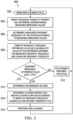
- FIG. 3 shows an example process or method 300 to operate an ultrasonic lens cleaning system.
- the method 300 can be implemented in certain examples by a controller or processor, such as the lens cleaning system driver controller 130 described hereinabove.
- the method 300 can include cleanliness detection operation, and selective ultrasonic lens cleaning operation as illustrated in FIG. 3 .
- the method 300 can also include an initial calibration or baseline processing sequence to establish one or more baseline profiles stored in the memory 150 including corresponding baseline frequency response values 152 and one or more baseline resonant frequency values corresponding to the associated lens cleaning system with a clean lens 202.
- the cleanliness detection operation uses baseline frequency response profile information stored in the memory 150 ( FIG. 1 ), including baseline frequency response values (e.g., impedance values) 152 and one or more baseline resonant frequencies FZB derived from the baseline frequency response values 152.
- baseline frequency response profile information stored in the memory 150 ( FIG. 1 ), including baseline frequency response values (e.g., impedance values) 152 and one or more baseline resonant frequencies FZB derived from the baseline frequency response values 152.
- FIG. 4 provides a graph 400 showing an example impedance magnitude response curve 402 as a function of transducer excitation frequency over a wide range 403, such as 10 to 1000 kHz in one example implementation.
- the impedance magnitude response curve 402 represents a baseline frequency response profile that can be stored in the memory 150, such as multiple frequency response values at different frequencies throughout the range 403. Other ranges may be used, preferably covering a usable range depending on the various masses of the structural components used in the optical system generally and the lens cleaning system in particular.
- FIG. 5 provides a corresponding graph 500 showing an example phase angle response curve 502 as a function of transducer excitation frequency over the same wide frequency range 403.
- the impedance curve 402 includes: a number of local maxima corresponding to poles of the mechanical system; and a number of local minima corresponding to system zeros.
- a local maxima of the phase curve 502 is at the geometric mean between the pole and zero frequencies of the impedance curve 402.
- the graphs 400 and 500 depict an example frequency range of interest 404 having a corresponding pole FPB (local maxima) and a zero FZM (local minima).
- the baseline processing or calibration can be implemented during a factory calibration operation, and/or in an installed host system when the lens 202 is known or believed to be clean.
- the controller 130 measures a baseline frequency response profile 150 that includes frequency response values 152 measured for the lens cleaning system with a clean lens 202 across a wide range 403 of frequencies that includes the frequency range of interest 404 in FIGS. 4 and 5 .
- the controller 130 stores the baseline frequency response profile in a memory 150 of the lens cleaning system.
- the controller 130 in certain implementations also determines one or more frequency ranges of interest 404. In the example of FIGS. 4 and 5 , the identified frequency range of interest 404 extends from approximately 20 kHz to 30 kHz for an example planar (i.e., flat) lens 202.
- the identified frequency range of interest 404 in this example includes the pole FPB at approximately 28.4 kHz and the zero FZB at approximately 28.2 kHz.
- the local zero FZB represents a natural resonant frequency of the lens cleaning system when the lens 202 is substantially clean (i.e., free of contaminants) for a planar or flat lens.
- the identified zero FZB corresponds to out of plane motion of the transducer 102.
- the baseline frequency response profile 402 also includes various other pole-zero pairs, including those illustrated at approximately 44 kHz.
- the pole-zero pair at 44 kHz represents in-plane motion, and is thus not used as a frequency range of interest as contaminants on the outer surface of the lens 202 are unlikely to have a significant effect on the resonant frequency of the system at this operating frequency of the transducer 102.
- not all of the natural frequencies change when contaminants are present on the lens 202, because the effective mass of the resonant mode does not change when material is added to the lens 202.
- the controller 130 can identify any number of eligible frequency ranges of interest for which a change in the resonant frequency of the system is indicative of the presence of contaminants on the lens 202. With one or more baseline resonant frequencies identified and corresponding frequency ranges of interest identified and stored, the controller 130 can operate to implement a cleaning regimen, such as a periodic cleaning cycle schedule during operation of the host system 148.
- resonance frequency of a mechanical system such as the lens cleaning apparatus of FIGS. 1 and 2 is often referred to as a natural frequency, ⁇ n , because the mechanical system naturally vibrates when excited by a sinusoid at this particular frequency.
- ⁇ n _ norm 1 ⁇ 1 1 + ⁇ m norm
- ⁇ m norm ⁇ m m is the normalized change in mass unitless .
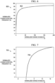
- FIG. 6 shows a graph 600 including a curve 602 illustrating the normalized change in natural frequency as a function of the normalized change in mass.
- the normalized change in natural frequency is very sensitive to a small normalized change in mass (e.g., less than 10%). For large normalized changes in mass (e.g., greater than 40%), the sensitivity is much less. However, the value of the normalized change is still quite large (e.g., approximately 90%) so a mass change is still easily detectible.
- a graph 700 in FIG. 7 includes a curve 702 over a smaller mass change range of -5% to + 17%.
- the natural frequency sensitivity to a change in mass is particularly pronounced for a small change, where a 10% normalized change in mass results in a normalized change in natural frequency of approximately 70%.
- the natural frequency sensitivity can be used to detect when materials are present on the lens 202.
- the controller 130 begins a new cleaning cycle at 302 in FIG. 3 .
- the controller 130 periodically initiates a new cleaning cycle during operation of the host system 148.
- the lens cleaning system may be installed in a vehicle-based camera system used to provide information to a control system of the host vehicle for use in one or more vehicle control functions, user interface functions, or other functions, and the controller 130 may periodically implement a new control cycle according to a predetermined or configurable time interval and/or upon request from the host system 148.
- the controller 130 controls the frequency Ft of the drive signal VDRV to vibrate the lens 202 at multiple frequencies in a frequency range of interest 404.
- the controller 130 sweeps the range of interest 404 as a continuous sweep and obtains samples of the feedback signals VFB and IFB for conversion by the A/D converters 134 and 135.
- the controller 130 sets the frequency Ft at multiple specific frequencies in the frequency range of interest 404 at 302, and obtains corresponding digital values corresponding to the converted feedback signals.
- the controller 130 computes sweep frequency response values 142 as the ratio of the voltage phasor value 138 to the current phasor value 139 for a given sample as described hereinabove in order to determine corresponding measured frequency response values corresponding to multiple frequencies in the range of interest 404.
- the controller 130 determines a measured resonant frequency of the system according to the feedback signal or signals IFB, VFB.
- the controller 130 uses the feedback signals to derive the measured frequency response values 142 from the sweep.
- the controller 130 identifies a local maxima or a local minima in the measured frequency response values 142 for the corresponding frequency range of interest 404.
- the controller 130 uses the zero locations to detect significant resonant frequency changes. The pole locations can alternatively be used in other implementations.
- the controller 130 compares the baseline resonant frequency value (e.g., FZB) with a measured resonant frequency value (e.g., FZM) and selectively determines the existence or absence of a threshold amount of contaminants on the lens 202 according to the difference.
- the controller 130 computes a resonant frequency difference value as the absolute value of the difference between the measured and baseline resonant frequency values (e.g.,
- the controller 130 compares the resonant frequency difference value
- the controller 130 determines that a threshold amount of contaminants are on the lens 202.
- the controller 130 includes an output 146 ( FIG. 1 ) that selectively provides a signal CONTAMINANT to a host system 148 in response to determination of the existence of the threshold amount of contaminants on the lens 202 at 314 in FIG. 3 .
- the controller 130 in certain examples uses the amplitude of the difference value
- the controller 130 determines one or more cleaning parameters according to the amplitude of
- controller 130 compares the amplitude of the difference value
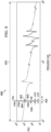
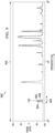
- FIGS. 8 and 9 provide impedance magnitude and phase angle response curves as a function of transducer excitation frequency, illustrating example curves for systems having a clean lens, a lens with water contaminants, and a lens with mud contaminants.
- the examples of FIGS. 8 and 9 correspond to the lens cleaning system response throughout the wide frequency range 403 illustrated in FIGS. 4 and 5 described hereinabove for a flat lens 202.
- a graph 800 in FIG. 8 includes a curve 402 corresponding to a clean lens 202 in the system (e.g., as also shown in FIG. 4 described hereinabove).
- the graph 800 further includes: a curve 802 representing the impedance magnitude response of the system with water contaminants on the lens 202; and a curve 804 showing the impedance magnitude response of the system with mud contaminants on the lens 202.
- a graph 900 in FIG. 9 shows: corresponding impedance phase response curve 402 corresponding to the clean lens 202; and curves 902 and 904 respectively showing impedance phase response for a lens 202 with water contaminants and mud contaminants.
- the graph 800 in FIG. 8 indicates the baseline pole frequency FPB, and the baseline zero frequency FZB within the frequency range of interest 404.
- FIGS. 8 and 9 illustrate an example impedance magnitude and phase response change for water and mud relative to a clean lens 202. Moreover, these graphs 800 and 900 demonstrate that the identified frequency range of interest 404 is suitable for detecting the presence or absence of contaminants on the lens 202, and that the system is capable of detecting the presence of multiple types of contaminants on the lens 202.
- the controller 130 is capable of determining measured frequency response curves 802 and 804 representing the frequency response of the lens cleaning system.
- the water contaminant curve 802 in this example has a local maxima in the frequency range of interest 404 designated as FPM1, and a local minima (zero) designated as FZM1.
- the controller 130 in one example determines the measured resonant frequency FZM1 (306 in FIG. 3 described hereinabove) based on measured frequency response values 142 and the corresponding feedback signals IFB and/or VFB, and computes the corresponding resonant frequency difference value
- the controller 130 determines the measured resonant frequency value FZM2 and computes the corresponding resonant frequency difference value
- FIGS. 10 and 11 further illustrate the capabilities of the driver 100 for lens cleanliness detection in the example frequency range of interest 404 with respect to water contaminants of different amounts on the lens 202.
- FIG. 10 provides a graph 1000 showing impedance magnitude response curves as a function of transducer excitation frequency in the range of interest 404 for a lens cleaning system with a clean lens 202, and with lenses 202 having different amounts of water contaminants in a first range.
- curve 402 shows the impedance magnitude response for a clean lens 202
- curve 1002 shows the impedance magnitude response for 50 ⁇ L of water
- curve 1004 shows a impedance magnitude response for 100 ⁇ L of water
- curve 1006 shows the impedance magnitude response for 150 ⁇ L of water
- curve 1008 shows the impedance magnitude response for 200 ⁇ L of water on the lens 202.
- the graph 1000 also illustrates: an example measured resonant frequency FZ1 determined by the controller 130 with respect to the curve 1002; and a computed resonant frequency difference value
- Another example measured resonant frequency FZ2 is shown in FIG. 10 , along with a corresponding resonant frequency difference value
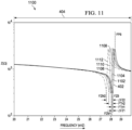
- FIG. 11 provides a graph 1100 throughout the frequency range of interest 404, including a curve 402 as described hereinabove for a clean lens 202. Also, the graph 1100 includes further curves 1102, 1104, 1106, 1108, 1110 and 1112 respectively corresponding to the impedance magnitude response due to the presence of 2 ⁇ L, 5 ⁇ L, 10 ⁇ L, 15 ⁇ L, 20 ⁇ L and 25 ⁇ L of water on the lens 202. FIG. 11 further indicates the above-described baseline pole and zero frequencies FPB and FZB for the case of a clean lens 202. Also, FIG.
- FIG. 11 shows the baseline pole frequency FPB, the baseline zero frequency FZB, and two example measured resonant frequencies FZM1 and FZM2 respectively corresponding to the measured resonant frequencies for the presence of 2 ⁇ L of water and 25 ⁇ L of water. Also, the graph 1100 shows the corresponding first and second resonant frequency difference values
- FIG. 11 shows an example of one possible first threshold value FTH1 that can be used by the controller 130.
- the controller 130 compares the corresponding first resonant frequency difference value
- the controller 130 compares the corresponding resonant frequency difference value
- Multiple additional threshold determinations can be implemented in order to provide multiple levels of configurable cleaning through adjustment of one or more cleaning parameters, such as cleaning duration, cleaning power level, etc.
- the change in frequency for a corresponding change in mass on the lens 202 is detectable.
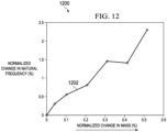
- FIG. 12 provides a graph 1200 including a curve 1202 illustrating normalized natural frequency change as a function of change in mass for the example lens cleaning system.
- This example curve 1202 corresponds with the theoretical modeling shown in FIGS. 6 and 7 described hereinabove, and verifies the capability of the controller 130 to use resonant frequency changes to successfully detect even small mass changes in the lens cleaning system to determine the relative cleanliness of the lens 202.
- the described system results in a curve 1202 with a slope around 5, which indicates that a 0.1% mass change produces a 0.5% frequency change.
- 2 mg mass change is affected, which produces a detectable change of 85 Hz.
- the controller 130 can selectively determine when cleaning cycles can be skipped in a periodic cleaning operating configuration, and the controller 130 can also advantageously tailor the cleaning (when needed) to the amount of contaminants present on the lens 202. For example, this objective can be accomplished by changing start and stop times (e.g., cleaning duration) for periodic cleaning operations, thereby reducing energy consumption.
- the frequency response analysis e.g., 304-312 in FIG.
- the controller 130 consumes less power than does a cleaning operation (318), and each time the controller 130 selectively determines that no cleaning is required (312), energy is saved by the overall lens cleaning system. Moreover, the system can intelligently employ higher power clean only when needed. As described hereinabove, moreover, the initial analysis and determination of the measured resonant frequency can provide control information for actual cleaning operation. For example, the controller 130 can intelligently clean at the measured resonant frequency and/or begin cleaning at the measured frequency and transition the cleaning frequency Ft toward the baseline frequency on the assumption that additional cleaning moves the system resonance point toward the baseline value.
- the identification of the appropriate starting frequency for the cleaning operation at 318 allows the system to more fully take advantage of the true natural frequency of the system that includes the detected contaminants, thereby improving the cleaning efficiency by energizing the transducer 102 at a resonant frequency of the overall system.
Description
- Camera systems are becoming more prevalent in automotive and other applications, such as vehicle cameras, security cameras, industrial automation systems, and in other applications and end-use systems. Operation of camera and lighting systems is facilitated by clean optical paths, which can be hindered by dirt, water or other debris, particularly in outdoor applications such as vehicle mounted camera systems, outdoor security camera systems, camera systems in industrial facilities, etc. For example, camera or light source lenses may be subject to ambient weather conditions, dirt and debris, and other contaminants which can obstruct or interfere with optical transmission through the lens. Automatic lens cleaning systems (LCSs) have been developed for vehicle and security cameras to self-clean a lens or lens cover. Such systems may include air or water spray apparatus, or mechanical wipers to wash a lens surface. Other lens cleaning systems electronically vibrate the lens to expel contaminants, water or other unwanted material from the lens cover to improve image quality or light transmission efficiency. Ultrasonic mechanical excitation or vibration has proved to be a more cost effective approach than water sprayer, mechanical wiper or air jet solutions, particularly to clean automotive camera system lenses (e.g., rear view and surround view systems). In many applications, clean lenses are important for correct system operation. However, ultrasonic cleaning systems can become worn through continuous use. Moreover, actuating a transducer to vibrate the lens consumes power, and unnecessary cleaning results in excessive power consumption. In vehicle systems or other applications using battery power, it is desired to conserve power, while maintaining adequate cleanliness of lenses for camera systems and lighting applications.
US 2016/266379 from Texas Instruments Inc. relates to an ultrasonic lens cleaning system with current sensing. - The invention is a driver for cleaning a lens as defined by claim 1, a lens cleaning system as defined by claim 6 and a method of operating a lens cleaning system as defined by claim 14. The invention includes a transducer mechanically coupled to a lens, a driver to provide an oscillating drive signal to the transducer, and a controller to control the drive signal frequency to vibrate the lens at frequencies in a range of interest. The controller determines a measured resonant frequency of the lens cleaning system in the frequency range of interest according to a transducer feedback signal, and selectively performs a lens cleaning operation if the measured resonant frequency differs from a baseline resonant frequency of the lens cleaning system for a clean lens. For example, the frequency response of the lens cleaning system is used to evaluate the resonant frequencies of interest. The frequency response can be measured as an impedance response, admittance response or other frequency domain equivalent.
- Described examples provide lens cleaning solutions to detect the presence of contaminants on the lens to facilitate intelligent cleaning when appropriate and to selectively refrain from lens cleaning when little or no contaminants are present. In certain examples, cleaning levels, such as transducer power level and/or cleaning duration are determined according to the amount of change from the baseline resonant frequency. This technique facilitates high power cleaning to remove large amounts of contaminants, while conserving power by using light cleaning to remove small detected amounts of contaminants, or to delay cleaning when the lens is determined to be clean.
-
-
FIG. 1 is a schematic diagram of a lens cleaning system. -
FIG. 2 is a partial sectional side elevation view of a camera lens assembly including a lens cleaning system. -
FIG. 3 is a flow diagram of an example lens cleaning process or method. -
FIG. 4 is a graph of an example impedance magnitude response curve as a function of excitation frequency for a lens cleaning system with a clean lens. -
FIG. 5 is a graph of an example impedance phase angle response curve as a function of excitation frequency for a lens cleaning system with a clean lens. -
FIGS. 6 and 7 are graphs of normalized natural frequency change as a function of change in mass for a lens cleaning system. -
FIG. 8 is a graph of example impedance magnitude response curves as a function of excitation frequency for a lens cleaning system with a clean lens, and with lenses having water and mud contaminants. -
FIG. 9 is a graph of example impedance phase angle response curves as a function of excitation frequency for a lens cleaning system with a clean lens, and with lenses having water and mud contaminants. -
FIG. 10 is a graph of an example impedance magnitude response curves as a function of excitation frequency in a frequency range of interest for a lens cleaning system with a clean lens, and with lenses having different amounts of water contaminants in a first range. -
FIG. 11 is a graph of an example impedance magnitude response curves as a function of excitation frequency in the frequency range of interest for a lens cleaning system with a clean lens, and with lenses having different amounts of water contaminants in a second range. -
FIG. 12 is a graph of normalized natural frequency change as a function of change in mass for a lens cleaning system. - In the drawings, like reference numerals refer to like elements throughout, and the various features are not necessarily drawn to scale. In this description, the term "couple" or "couples" includes indirect or direct electrical or mechanical connection or combinations thereof. For example, if a first device couples to or is coupled with a second device, that connection may be through a direct electrical connection, or through an indirect electrical connection via one or more intervening devices and connections.
-
FIG. 1 shows an ultrasonic lens cleaning system with a driver integrated circuit (IC) 100, andFIG. 2 shows acamera lens assembly 200 including an ultrasonic lens cleaning system. As shown inFIG. 2 , thelens assembly 200 includes a cylindrical or "ring"transducer 102 which is mechanically coupled to vibrate alens 202. In one example, thetransducer 102 is bonded to thelens 202. Although illustrated in the context of a camera lens system, various techniques of this description can also be used in lighting systems or other optical systems, with or without a camera. As described herein, the apparatus and techniques facilitate automatic detection of the presence or substantial absence of contaminants on thelens 202, and can be advantageously employed for selective lens cleaning when a threshold amount of contaminants are detected. Also, certain examples provide for threshold based determination of one or more cleaning parameters, such as cleaning power and/or cleaning duration based on determination of an amount of contaminants present on thelens 202. The techniques of this description can be used for contaminant detection alone. Also, for example, the described apparatus and methods can be employed in lens cleaning systems having acontroller 130 and atransducer 102 which can also be used for automatic lens cleaning operations. As used herein, a lens can be: a focusing element or other lens that implements optical shaping or other optical effect to aid camera imaging; or a lens cover or optical window that merely provides protection for further optical elements without performing any imaging functions. - The
lens 202 in one example is a "fisheye" lens having a curved outer surface as shown inFIG. 2 . In other examples, a flat lens or a lens having a different profile can be used. The lens assembly in this example is mounted to a generallycylindrical housing 204 using acylindrical cap fastener 201 and is sealed using an O-ring 208 extending between an edge of thelens 202 and thefastener 201 to prevent ingress of water or debris into the interior of thehousing 204. In one example, thehousing 204 can be mounted to a motor vehicle to operate as a lens cover for a rear backup camera, a forward-facing camera or a side-facing camera. In other examples, theassembly 200 can be mounted to a building or a light pole, such as for security camera or lighting applications. In other examples, theassembly 200 can be used for interior security monitoring systems, such as within a commercial or residential building. In this example, a series of generally flatsecondary lenses 210 are disposed within the inner surfaces of thespacer 206. Thesecondary lenses 210 and thefisheye lens 202 provide an optical path for imaging by acamera 212. Thetransducer 102 includes lead wires orterminals opening 216 in abase 214 of thehousing 204 for connection with thedriver IC 100. In the example ofFIG. 2 , thelens 202 is mounted into thecylindrical housing 204 with a cylindricalinner spacer structure 206. Thetransducer 102 in this example is a cylindrical ring-shaped piezo-electric transducer disposed between theinner spacer 206 and the outer wall of thehousing 204. - As best shown in
FIG. 1 , thedriver IC 100 includes a power input pin orpad 106 that receives input power from a power supply orpower source 104, such as a battery providing a battery voltage signal VB with respect to areference node 108 having a reference voltage (e.g., GND). Thedriver IC 100 includes apower management circuit 110 that receives the battery voltage signal VB and provides one or more supply voltages (not shown) to power the internal circuitry of thedriver 100. Also, the IC 100 includes an output withterminals lead wires transducer 102. In operation, thedriver 100 output provides an oscillating drive signal VDRV at a non-zero frequency Ft to thetransducer 102 to vibrate thelens 202. As described further hereinbelow, the controlled vibration of thelens 202 via excitation of thetransducer 102 facilitates cleaning or removal of contaminants or debris from the outer surface of thelens 202. Also, thetransducer 102 is controlled by thedriver 100 in different modes for assessing the cleanliness of thelens 202, and for selectively cleaning thelens 202 when appropriate according to a determined presence and amount of contaminants on thelens 202. In certain examples, moreover, thedriver IC 100 determines one or more baseline profiles to identify resonant frequencies for the system having aclean lens 202 to facilitate subsequent determination of the presence or absence of contaminants on thelens 202. - As shown in
FIG. 1 , thedriver IC 100 includes a controller orcontrol circuit 130 with asignal generator 116. In one example, thecontroller 130 is a processor with an associated electronic memory. Thecontroller 130 implements various cleaning, cleanliness detection, and optional calibration or baseline processing functions by controlling the oscillatory frequency Ft of thetransducer 102. In one example, thecontroller 130 includes a sweep and resonance tracking,cleanliness detection circuit 122 with anoutput 124 that provides a desired frequency Ft to asignal generator circuit 116. In another possible implementation, thecontroller 130 is implemented in a processor, such as a DSP or other programmable digital circuit, which implements sweep and resonance tracking, cleanliness detection and calibration functions through execution of instructions stored in an associated memory to generate the frequency Ft as a digital value representing a desired frequency Ft of the drive signal VDRV. In one example, thesignal generator 116 is a pulse width modulation (PWM) output of the processor that implements thecontroller 130. Thesignal generator circuit 116 provides an output signal VS that oscillates at a non-zero frequency Ft. In certain implementations, thecontroller 130 includes an integral electronic memory, or is operatively connected to an externalelectronic memory 150 that stores program instructions implemented by the processor, and stores baseline profiles that include baseline frequency response values 152, such asbaseline impedance values 152 that represent the frequency response of a lens cleaning system having aclean lens 202 as described further hereinbelow. - The
driver IC 100 further includes anamplifier 118 which amplifies the output signal VS to generate the oscillating drive signal VDRV. In this manner, thecontroller 130 provides the desired frequency Ft of the drive signal VDRV, and thereby control the oscillatory frequency of thetransducer 102 for cleaning thelens 202 and/or to implement baseline calibration and cleanliness detection functions as described herein. In one example, theamplifier 118 is a full H-bridge amplifier circuit with first and second outputs individually coupled with thetransducer terminals transducer 102. In the example ofFIG. 1 , moreover, an L-C filter circuit 119 is connected between the amplifier outputs and thetransducer terminals first filter circuit 119a connected between a first output of theamplifier 118 and thefirst transducer terminal 131a; and asecond filter circuit 119b connected between the second output of theamplifier 118 and thesecond transducer terminal 131b. A variety of differentsignal generator circuits 116 can be used, including a PWM processor output that generates a modulated square wave signal VS, or other signal generator circuitry to provide modulated sinusoidal, modulated triangular, modulated saw tooth or other waveforms having a non-zero signal frequency Ft. In one example, the first output of theamplifier 118 delivers an oscillating drive signal to thetransducer 102 and the second amplifier output delivers an oscillating drive signal to thetransducer 102 which is 180 degrees out of phase with respect to the first output. - In certain examples, the
amplifier 118 can provide a single ended output through thefirst filter circuit 119a to thefirst output terminal 112, and the return current from thetransducer 102 flows through thesecond filter circuit 119b to return to the second output of theamplifier 118. In the illustrated example, theamplifier 118 provides a differential output to thefilters individual filter circuits transducer 102. In this manner, theamplifier 118 amplifies the signal generator output signal VS and delivers an oscillating drive signal VDRV to thetransducer 102. The filter circuit 119 advantageously allows the use of a modulated square wave output from thePWM signal generator 116 to provide a generally sinusoidal oscillating signal VDRV to vibrate thetransducer 102 and the mechanically coupledlens 202. - The
driver IC 100 also includes a feedback circuit that generates one or more feedback signals that represent an electrical property of thetransducer 102. In one example, the feedback circuit includes a current sensor or current transducer 120 a current feedback signal IFB representing a current IDRV flowing through thetransducer 102. The feedback circuitry also includes adifferential amplifier 132 with inputs connected across thetransducer output terminals controller 130. In one example, thecontroller 130 includes analog-to-digital (A/D)converters controller 130, theamplifier 118, the output filter circuitry 119 and the feedback circuitry are fabricated in a singleintegrated circuit 100. Thedriver 100 can be provided on a single printed circuit board (PCB) along with a camera 212 (or a light source) to provide a compact solution for various vehicle-based and/or security camera systems or lighting systems generally. - The
driver IC 100 operates in a normal mode to selectively provide ultrasonic lens cleaning functions in conjunction with the associatedtransducer 102. The outer surface of thelens 202 inFIG. 2 may be exposed to dirt, debris, water and other optical obstructions, referred to herein as contaminants, particularly in outdoor installations. Thedriver 100 provides an oscillating signal to cause thetransducer 102 to vibrate thelens 202 to facilitate or promote cleaning of thelens 202. In one example, thedriver 100 provides an ultrasonic drive signal or voltage waveform VDRV to actuate thetransducer 102 and cause thetransducer 102 to mechanically vibrate thelens 202 using ultrasonic waves to remove dirt and/or water from the surface of thelens 202. Mechanical oscillation or motion of thelens 202 at ultrasonic waves of a frequency at or close to a system resonant frequency can facilitate energy efficient removal of water, dirt and/or debris from thelens 202. Thedriver IC 100 in one example provides a closed loop system using the feedback signals IFB and/or VFB during lens cleaning operation. In one example, thedriver IC 100 regulates operation at or near a local minima or maxima in a current or impedance signal value ascertained from one or more feedback signals. In another possible implementation, thecontroller 130 controls the frequency Ft according to a measured resonant frequency FZM determined during cleanliness detection operation, in order to facilitate removal of a specific detected amount of contaminants on thelens 202. Thecontroller 130 in one example uses the converted values from the A/D converters 134 and/or 135 to implement closed-loop control in driving thetransducer 102 for lens cleaning operations. - The
controller 130 also operates in a cleanliness detection mode to detect the presence or absence of contaminants on thelens 102. In an example implementation, thecontroller 130 determines the measured resonant frequency FZM during a cleanliness detection operation, and if cleaning is determined to be appropriate, begins the cleaning operation at a frequency Ft corresponding to the determined measured resonant frequency FZM, and gradually transitions the operating frequency Ft to a previously determined baseline resonant frequency FZB over the determined cleaning duration for a given cleaning operation. Moreover, as described hereinbelow, thecontroller 130 in certain examples implements selective cleaning in a given cleaning cycle to first verify whether cleaning is appropriate, and if so the amount or level of cleaning to be done. If thelens 202 is determined to be substantially clean, thecontroller 130 refrains from performing a cleaning operation in that cleaning cycle. In this manner, thecontroller 130 advantageously conserves power and selectively avoids cleaning if unnecessary. Also, the initial determination of a measured resonant frequency FZM during cleanliness detection mode operation allows thecontroller 130 to selectively employ multiple levels of cleaning based on the measured resonant frequency FZM. Also, thecontroller 130 selectively determines corresponding cleaning parameters, such as cleaning duration and/or cleaning power based on the measured resonant frequency FZM. As shown inFIG. 1 , moreover, thecontroller 130 in certain examples an output signal CONTAMINANT to ahost system 148 via adriver IC output 146 to indicate detection of contaminants on thelens 202. - As shown in
FIG. 1 , the analog feedback signals VFB and IFB are converted to digital values by the A/D converters controller 130 in one example calculates discrete Fourier transform (DFT)components converters controller 130 also implements a complex division (DIVIDE) function 140 to compute sweep frequency response values, such assweep impedance values 142 as the ratio of thevoltage phasor value 138 to thecurrent phasor value 139 for a given sample. In this regard, the A/D converters operate at a sufficiently high sample frequency to obtain a stream of digital values representing the feedback voltage and current associated with the driventransducer 102. The processing implemented by execution of program instructions by the processor of thecontroller 130 provides a stream of frequency response values (e.g., impedance values 142). For a sweep of multiple frequencies in a predetermined frequency range of interest, a series of frequency response values 142 provide an frequency response profile as a function of frequency. - The presence or absence of contaminants on the
lens 202 affects the mass of the lens cleaning system, and thus impacts the resonant frequency. Local minima and/or maxima of the measured frequency response (e.g., impedance) profile can be used to identify or determine a measured resonance or resonant frequency FZM associated with the mechanical impedance of the lens cleaning system including the additional mass of contaminants on thelens 202. Based on this principle, thecontroller 130 in one example compares a measured resonant frequency value FZM determined through impedance measurements at different frequencies, and compare the measured resonant frequency value with a baseline resonant frequency value FZB corresponding to a lens cleaning system having a substantiallyclean lens 202. The difference between these frequency values can be compared with one or more thresholds in order to automatically take one or more actions or refrain from one or more control actions. For example, if a first threshold amount of difference is not detected, thecontroller 130 can refrain from performing a lens cleaning operation until a subsequent cleaning cycle. In certain examples, if the initial threshold amount of frequency change is detected through this comparison, thecontroller 130 can further compare the frequency difference with a second higher threshold value, and set one or more cleaning parameters accordingly. - In the illustrated example, the
controller 130 controls the frequency Ft of the drive signal VDRV to vibrate thelens 202 at multiple frequencies in a frequency range of interest. In one implementation, thecontroller 130 performs a frequency sweep for one or more predetermined frequency ranges of interest. Thecontroller 130 digitally converts the feedback signals during the frequency sweep, obtains frequencyspectrum phasor information values 140 to obtain sweep frequency response values 142 corresponding to the frequencies in the range of interest. Thecontroller 130 also determines a measured resonant frequency FZM from the sweep frequency response values 142 and implements acomparison function 144 that compares the measured resonant frequency FZM to a baseline resonant frequency value FZB associated with corresponding ones of the frequencies in a given frequency range of interest for aclean lens 202. Thecontroller 130 uses the comparison to selectively determine the existence or presence of contaminants on thelens 202 according to an absolute value of the difference between the measured resonant frequency FZM and the baseline resonant frequency value FZB. This comparison can be performed in one example according to one or more threshold values. Thecontroller 130 does not need to perform a continuous sweep, and instead may control the lens transducer drive signal frequency Ft to vibrate thelens 202 at one or more frequencies included in a predetermined frequency range of interest and computes the corresponding frequency response values 142 and one or more measured resonant frequency values FZM according to the driver feedback signals VFB, IFB. - Referring also to
FIGS. 3-5 ,FIG. 3 shows an example process ormethod 300 to operate an ultrasonic lens cleaning system. Themethod 300 can be implemented in certain examples by a controller or processor, such as the lens cleaningsystem driver controller 130 described hereinabove. In various implementations, themethod 300 can include cleanliness detection operation, and selective ultrasonic lens cleaning operation as illustrated inFIG. 3 . In further possible implementations, themethod 300 can also include an initial calibration or baseline processing sequence to establish one or more baseline profiles stored in thememory 150 including corresponding baseline frequency response values 152 and one or more baseline resonant frequency values corresponding to the associated lens cleaning system with aclean lens 202. In one example, thecontroller 130 of the lens cleaning system ofFIGS. 1 and2 is programmed or configured to implement themethod 300 for detection of threshold amounts of contaminants on thelens 202 at 304-310, and for selective ultrasonic cleaning at 314-318. The cleanliness detection operation uses baseline frequency response profile information stored in the memory 150 (FIG. 1 ), including baseline frequency response values (e.g., impedance values) 152 and one or more baseline resonant frequencies FZB derived from the baseline frequency response values 152. -
FIG. 4 provides agraph 400 showing an example impedancemagnitude response curve 402 as a function of transducer excitation frequency over awide range 403, such as 10 to 1000 kHz in one example implementation. The impedancemagnitude response curve 402 represents a baseline frequency response profile that can be stored in thememory 150, such as multiple frequency response values at different frequencies throughout therange 403. Other ranges may be used, preferably covering a usable range depending on the various masses of the structural components used in the optical system generally and the lens cleaning system in particular.FIG. 5 provides acorresponding graph 500 showing an example phaseangle response curve 502 as a function of transducer excitation frequency over the samewide frequency range 403. In this example, theimpedance curve 402 includes: a number of local maxima corresponding to poles of the mechanical system; and a number of local minima corresponding to system zeros. A local maxima of thephase curve 502 is at the geometric mean between the pole and zero frequencies of theimpedance curve 402. Thegraphs interest 404 having a corresponding pole FPB (local maxima) and a zero FZM (local minima). - The baseline processing or calibration can be implemented during a factory calibration operation, and/or in an installed host system when the
lens 202 is known or believed to be clean. In one example, thecontroller 130 measures a baselinefrequency response profile 150 that includes frequency response values 152 measured for the lens cleaning system with aclean lens 202 across awide range 403 of frequencies that includes the frequency range ofinterest 404 inFIGS. 4 and5 . Thecontroller 130 stores the baseline frequency response profile in amemory 150 of the lens cleaning system. Thecontroller 130 in certain implementations also determines one or more frequency ranges ofinterest 404. In the example ofFIGS. 4 and5 , the identified frequency range ofinterest 404 extends from approximately 20 kHz to 30 kHz for an example planar (i.e., flat)lens 202. The identified frequency range ofinterest 404 in this example includes the pole FPB at approximately 28.4 kHz and the zero FZB at approximately 28.2 kHz. The local zero FZB represents a natural resonant frequency of the lens cleaning system when thelens 202 is substantially clean (i.e., free of contaminants) for a planar or flat lens. In this example, the identified zero FZB corresponds to out of plane motion of thetransducer 102. - In
FIGS. 4 and5 , the baselinefrequency response profile 402 also includes various other pole-zero pairs, including those illustrated at approximately 44 kHz. In this example, for a flat orplanar lens 202, the pole-zero pair at 44 kHz represents in-plane motion, and is thus not used as a frequency range of interest as contaminants on the outer surface of thelens 202 are unlikely to have a significant effect on the resonant frequency of the system at this operating frequency of thetransducer 102. In certain systems, not all of the natural frequencies change when contaminants are present on thelens 202, because the effective mass of the resonant mode does not change when material is added to thelens 202. For example, the natural frequency of 44 kHz inFIGS. 4 and5 corresponds to a radial mode whose effective mass does not change because the shear force is not strong enough to move the contaminants when thelens 202 vibrates in the radial direction. Thecontroller 130 can identify any number of eligible frequency ranges of interest for which a change in the resonant frequency of the system is indicative of the presence of contaminants on thelens 202. With one or more baseline resonant frequencies identified and corresponding frequency ranges of interest identified and stored, thecontroller 130 can operate to implement a cleaning regimen, such as a periodic cleaning cycle schedule during operation of thehost system 148. - Referring also to
FIGS. 6 and 7 , resonance frequency of a mechanical system such as the lens cleaning apparatus ofFIGS. 1 and2 is often referred to as a natural frequency, ωn , because the mechanical system naturally vibrates when excited by a sinusoid at this particular frequency. The natural frequency can be represented mathematically according to the following equation (1):


-
FIG. 6 shows agraph 600 including acurve 602 illustrating the normalized change in natural frequency as a function of the normalized change in mass. As shown in thegraph 600, the normalized change in natural frequency is very sensitive to a small normalized change in mass (e.g., less than 10%). For large normalized changes in mass (e.g., greater than 40%), the sensitivity is much less. However, the value of the normalized change is still quite large (e.g., approximately 90%) so a mass change is still easily detectible. Agraph 700 inFIG. 7 includes acurve 702 over a smaller mass change range of -5% to + 17%. The natural frequency sensitivity to a change in mass is particularly pronounced for a small change, where a 10% normalized change in mass results in a normalized change in natural frequency of approximately 70%. The natural frequency sensitivity can be used to detect when materials are present on thelens 202. - Referring also to
FIGS. 7 and8 , thecontroller 130 begins a new cleaning cycle at 302 inFIG. 3 . In one possible implementation, thecontroller 130 periodically initiates a new cleaning cycle during operation of thehost system 148. For example, the lens cleaning system may be installed in a vehicle-based camera system used to provide information to a control system of the host vehicle for use in one or more vehicle control functions, user interface functions, or other functions, and thecontroller 130 may periodically implement a new control cycle according to a predetermined or configurable time interval and/or upon request from thehost system 148. - At 304 in
FIG. 3 , thecontroller 130 controls the frequency Ft of the drive signal VDRV to vibrate thelens 202 at multiple frequencies in a frequency range ofinterest 404. In one example, thecontroller 130 sweeps the range ofinterest 404 as a continuous sweep and obtains samples of the feedback signals VFB and IFB for conversion by the A/D converters controller 130 sets the frequency Ft at multiple specific frequencies in the frequency range ofinterest 404 at 302, and obtains corresponding digital values corresponding to the converted feedback signals. Thecontroller 130 computes sweep frequency response values 142 as the ratio of thevoltage phasor value 138 to thecurrent phasor value 139 for a given sample as described hereinabove in order to determine corresponding measured frequency response values corresponding to multiple frequencies in the range ofinterest 404. - At 306, the
controller 130 determines a measured resonant frequency of the system according to the feedback signal or signals IFB, VFB. In the illustrated implementation, thecontroller 130 uses the feedback signals to derive the measured frequency response values 142 from the sweep. In one example, thecontroller 130 identifies a local maxima or a local minima in the measured frequency response values 142 for the corresponding frequency range ofinterest 404. In the following description, thecontroller 130 uses the zero locations to detect significant resonant frequency changes. The pole locations can alternatively be used in other implementations. - At 308 and 310, the
controller 130 compares the baseline resonant frequency value (e.g., FZB) with a measured resonant frequency value (e.g., FZM) and selectively determines the existence or absence of a threshold amount of contaminants on thelens 202 according to the difference. At 308 inFIG. 3 , thecontroller 130 computes a resonant frequency difference value as the absolute value of the difference between the measured and baseline resonant frequency values (e.g., |ΔFZ| = |FZB - FZMI) for the evaluated frequency range ofinterest 404. At 310, thecontroller 130 compares the resonant frequency difference value |ΔFZ| with a first threshold non-zero FTH1 to make an initial determination of whether the lens has sufficient amount of contaminants to require cleaning. For example, thecontroller 130 determines that a threshold amount of contaminants are on thelens 202 if the resonant frequency difference value |ΔFZ| is greater than FTH1. If the resonant frequency difference value does not exceed the threshold (NO at 310), thecontroller 130 determines at 312 that no cleaning is required for this cleaning cycle, and theprocess 300 returns to begin the next cleaning cycle at 302 as described hereinabove. - At 314 in
FIG. 3 , if a threshold amount of frequency change has occurred (YES at 310), thecontroller 130 determines that a threshold amount of contaminants are on thelens 202. In one example, thecontroller 130 includes an output 146 (FIG. 1 ) that selectively provides a signal CONTAMINANT to ahost system 148 in response to determination of the existence of the threshold amount of contaminants on thelens 202 at 314 inFIG. 3 . - The
controller 130 in certain examples uses the amplitude of the difference value |ΔFZ| to distinguish between different amounts of contaminants on thelens 202, such as using a second threshold comparison. This architecture facilitates appropriate remedial action by the host system. At 316, thecontroller 130 determines one or more cleaning parameters according to the amplitude of |ΔFZ|. In one example, thecontroller 130 compares the amplitude of the difference value |ΔFZ| with a second threshold FTH2, where FTH2 > FTH1. Also, thecontroller 130 in certain implementations compares the amplitude of the difference value |ΔFZ| to selectively set one or more cleaning parameters for any implemented cleaning process at 318, such as the number of cleaning phases, the cleaning duration of each phase, the cleaning power of each phase, the cleaning voltage of each phase, the cleaning frequency range of each phase, the cleaning frequency ramp rate of each phase, etc. -
FIGS. 8 and9 provide impedance magnitude and phase angle response curves as a function of transducer excitation frequency, illustrating example curves for systems having a clean lens, a lens with water contaminants, and a lens with mud contaminants. The examples ofFIGS. 8 and9 correspond to the lens cleaning system response throughout thewide frequency range 403 illustrated inFIGS. 4 and5 described hereinabove for aflat lens 202. Agraph 800 inFIG. 8 includes acurve 402 corresponding to aclean lens 202 in the system (e.g., as also shown inFIG. 4 described hereinabove). Thegraph 800 further includes: acurve 802 representing the impedance magnitude response of the system with water contaminants on thelens 202; and acurve 804 showing the impedance magnitude response of the system with mud contaminants on thelens 202. Agraph 900 inFIG. 9 shows: corresponding impedancephase response curve 402 corresponding to theclean lens 202; and curves 902 and 904 respectively showing impedance phase response for alens 202 with water contaminants and mud contaminants. As described hereinabove in connection withFIG. 4 , thegraph 800 inFIG. 8 indicates the baseline pole frequency FPB, and the baseline zero frequency FZB within the frequency range ofinterest 404. Thecurve 402 inFIG. 9 includes a local maxima at the frequency FZB corresponding to the local minima (zero) in thecurve 402 ofFIG. 8. FIGS. 8 and9 illustrate an example impedance magnitude and phase response change for water and mud relative to aclean lens 202. Moreover, thesegraphs interest 404 is suitable for detecting the presence or absence of contaminants on thelens 202, and that the system is capable of detecting the presence of multiple types of contaminants on thelens 202. - As further shown in
FIG. 8 , thecontroller 130 is capable of determining measured frequency response curves 802 and 804 representing the frequency response of the lens cleaning system. Thewater contaminant curve 802 in this example has a local maxima in the frequency range ofinterest 404 designated as FPM1, and a local minima (zero) designated as FZM1. Thecontroller 130 in one example determines the measured resonant frequency FZM1 (306 inFIG. 3 described hereinabove) based on measured frequency response values 142 and the corresponding feedback signals IFB and/or VFB, and computes the corresponding resonant frequency difference value |ΔFZ1| for the water contaminant example indicated inFIG. 8 . Similarly for mud contaminants on thelens 202, thecontroller 130 determines the measured resonant frequency value FZM2 and computes the corresponding resonant frequency difference value |ΔFZ2| shown inFIG. 8 . -
FIGS. 10 and11 further illustrate the capabilities of thedriver 100 for lens cleanliness detection in the example frequency range ofinterest 404 with respect to water contaminants of different amounts on thelens 202.FIG. 10 provides agraph 1000 showing impedance magnitude response curves as a function of transducer excitation frequency in the range ofinterest 404 for a lens cleaning system with aclean lens 202, and withlenses 202 having different amounts of water contaminants in a first range. For example,curve 402 shows the impedance magnitude response for aclean lens 202,curve 1002 shows the impedance magnitude response for 50 µL of water,curve 1004 shows a impedance magnitude response for 100 µL of water,curve 1006 shows the impedance magnitude response for 150 µL of water, andcurve 1008 shows the impedance magnitude response for 200 µL of water on thelens 202. Thegraph 1000 also illustrates: an example measured resonant frequency FZ1 determined by thecontroller 130 with respect to thecurve 1002; and a computed resonant frequency difference value |ΔFZ1| computed by thecontroller 130 showing the frequency response difference due to the presence of 50 µL of water on thelens 202. Another example measured resonant frequency FZ2 is shown inFIG. 10 , along with a corresponding resonant frequency difference value |ΔFZ2| corresponding to thecurve 1004 illustrating the change due to the presence of 100 µL of water. -
FIG. 11 provides agraph 1100 throughout the frequency range ofinterest 404, including acurve 402 as described hereinabove for aclean lens 202. Also, thegraph 1100 includesfurther curves lens 202.FIG. 11 further indicates the above-described baseline pole and zero frequencies FPB and FZB for the case of aclean lens 202. Also,FIG. 11 shows the baseline pole frequency FPB, the baseline zero frequency FZB, and two example measured resonant frequencies FZM1 and FZM2 respectively corresponding to the measured resonant frequencies for the presence of 2 µL of water and 25 µL of water. Also, thegraph 1100 shows the corresponding first and second resonant frequency difference values |ΔFZ1| and |ΔFZ2| for the 2 and 25 µL water contaminant cases. As described hereinabove, thecontroller 130 in certain examples compares the computed resonant frequency difference value |ΔFZ| to a first threshold FTH1.FIG. 11 shows an example of one possible first threshold value FTH1 that can be used by thecontroller 130. In this case, for a contaminant amount of 2 µL, thecontroller 130 compares the corresponding first resonant frequency difference value |ΔFZ1| with the first threshold value FTH1, and determines (310 inFIG. 3 ) that no cleaning is required because the |ΔFZ1|< FTH1. In the illustrated example, therefore, thecontroller 130 advantageously conserves energy by refraining from performing a lens cleaning operation for the current cleaning cycle (e.g., 312 inFIG. 3 ). - Continuing with this example, if the amount of contaminants on the
lens 202 is instead 25 µL of water (curve 1112 inFIG. 11 ), thecontroller 130 compares the corresponding resonant frequency difference value |ΔFZ2| with the first threshold value FTH1, and determines (310 inFIG. 3 ) that cleaning is appropriate because the |ΔFZ2| > FTH1. In this case, moreover, thecontroller 130 then compares the resonant frequency difference value |ΔFZ2| to the second threshold value FTH2. Because |ΔFZ2| > FTH2, thecontroller 130 determines the cleaning power level and/or cleaning duration at 316 inFIG. 3 in order to provide a high level of cleaning in order to remove the significantly higher 25 µL amount of water contaminants on thelens 202. Multiple additional threshold determinations can be implemented in order to provide multiple levels of configurable cleaning through adjustment of one or more cleaning parameters, such as cleaning duration, cleaning power level, etc. In these examples using water contaminants, the change in frequency for a corresponding change in mass on thelens 202 is detectable. -
FIG. 12 provides agraph 1200 including acurve 1202 illustrating normalized natural frequency change as a function of change in mass for the example lens cleaning system. Thisexample curve 1202 corresponds with the theoretical modeling shown inFIGS. 6 and 7 described hereinabove, and verifies the capability of thecontroller 130 to use resonant frequency changes to successfully detect even small mass changes in the lens cleaning system to determine the relative cleanliness of thelens 202. For example, the described system results in acurve 1202 with a slope around 5, which indicates that a 0.1% mass change produces a 0.5% frequency change. In the case of 2 mL of water contaminants on thelens 202, only a 2 mg mass change is affected, which produces a detectable change of 85 Hz. - The examples described herein advantageously facilitate identification of the presence or absence of contaminants on the
lens 202, and provide various benefits in operation of the lens cleaning system based on the cleanliness detection capabilities. For example, thecontroller 130 can selectively determine when cleaning cycles can be skipped in a periodic cleaning operating configuration, and thecontroller 130 can also advantageously tailor the cleaning (when needed) to the amount of contaminants present on thelens 202. For example, this objective can be accomplished by changing start and stop times (e.g., cleaning duration) for periodic cleaning operations, thereby reducing energy consumption. In this regard, the frequency response analysis (e.g., 304-312 inFIG. 3 ) consumes less power than does a cleaning operation (318), and each time thecontroller 130 selectively determines that no cleaning is required (312), energy is saved by the overall lens cleaning system. Moreover, the system can intelligently employ higher power clean only when needed. As described hereinabove, moreover, the initial analysis and determination of the measured resonant frequency can provide control information for actual cleaning operation. For example, thecontroller 130 can intelligently clean at the measured resonant frequency and/or begin cleaning at the measured frequency and transition the cleaning frequency Ft toward the baseline frequency on the assumption that additional cleaning moves the system resonance point toward the baseline value. In this manner, the identification of the appropriate starting frequency for the cleaning operation at 318 allows the system to more fully take advantage of the true natural frequency of the system that includes the detected contaminants, thereby improving the cleaning efficiency by energizing thetransducer 102 at a resonant frequency of the overall system. - Modifications are possible in the described embodiments, and other embodiments are possible, within the scope of the claims.
Claims (15)
- A driver (100) for a lens cleaning system (200), the lens cleaning system (200) comprising a lens (202) and a transducer (102) mechanically coupled to the lens (202), the driver (100) comprising:an output configured to provide an oscillating drive signal (VDRV) at a non-zero frequency to the transducer (102) to vibrate the lens (202);a feedback circuit coupled across transducer output terminals of the output to generate a feedback signal (IFB, VFB); anda controller (130) configured to:control the frequency of the drive signal (VDRV) to vibrate the lens (202) at a plurality of frequencies in a frequency range of interest,determine a measured resonant frequency of the lens cleaning system in the frequency range of interest according to the feedback signal (IFB, VFB), andselectively cause the output to provide the drive signal (VDRV) to vibrate the lens (202) to perform a lens cleaning operation if the measured resonant frequency differs from a baseline resonant frequency of the lens cleaning system for a clean lens (202);characterised in thatthe feedback signal (IFB,VFB) comprises the transducer voltage (VFB).
- The driver of claim 1,wherein the feedback circuit is configured to generate a current feedback signal (IFB) representing a current flowing in the transducer (102), and to generate a voltage feedback signal (VFB) representing a voltage of the transducer (102); andwherein the controller (130) is configured to:determine measured frequency response values individually corresponding to one of the frequencies in the frequency range of interest according to the current feedback signal (IFB) and the voltage feedback signal (VFB),determine the measured resonant frequency of the lens cleaning system in the frequency range of interest according to the measured frequency response values,compute a resonant frequency difference value as an absolute value of a difference between the measured resonant frequency and the baseline resonant frequency, anddetermine that a threshold amount of contaminants are on the lens (202) if the resonant frequency difference value is greater than a non-zero first frequency threshold value.
- The driver of claim 2, wherein the controller (130) is configured to determine at least one of a number of cleaning phases, a voltage level of each cleaning phase, a frequency sweep range of each cleaning phase, and a frequency sweep rate of each cleaning phase according to the resonant frequency difference value and a second frequency threshold value, the second frequency threshold value being greater than the first frequency threshold value.
- The driver of claim 1, wherein the controller (130) is configured to selectively perform the lens cleaning operation using one of a cleaning power level and a cleaning duration determined according to the measured resonant frequency.
- The driver of claim 1, wherein the output, the feedback circuit, and the controller (130) are fabricated in a single integrated circuit.
- A lens cleaning system to clean a lens, comprising:a transducer (102) mechanically coupled to the lens (202);a driver according to claim 1 configured to provide the oscillating drive signal (VDRV) at a non-zero frequency to the transducer (102) to vibrate the lens (202).
- The lens cleaning system of claim 6,wherein the feedback circuit is configured to generate a current feedback signal (IFB) representing a current flowing in the transducer (102); andwherein the controller (130) is configured to:determine measured frequency response values individually corresponding to one of the frequencies in the frequency range of interest according to the current feedback signal (IFB) and the voltage feedback signal (VFB),determine the measured resonant frequency of the lens cleaning system in the frequency range of interest according to the measured frequency response values,compute a resonant frequency difference value as an absolute value of a difference between the measured resonant frequency and the baseline resonant frequency, anddetermine that a threshold amount of contaminants are on the lens (202) if the resonant frequency difference value is greater than a non-zero first frequency threshold value.
- The driver of claim 2 or the lens cleaning system of claim 7, wherein the controller (130) is configured to:determine a frequency response profile of the lens cleaning system in the frequency range of interest according to the measured frequency response values; anddetermine the measured resonant frequency as a frequency corresponding to a local minima or local maxima of the frequency response profile.
- The lens cleaning system of claim 7, wherein the controller (130) is configured to determine at least one of a number of cleaning phases, a voltage level of each cleaning phase, a frequency sweep range of each cleaning phase, a frequency sweep rate of each cleaning phase, and a duration of each cleaning phase according to the resonant frequency difference value and a second frequency threshold value, the second frequency threshold value being greater than the first frequency threshold value.
- The lens cleaning system of claim 6, wherein the controller (130) is configured to selectively perform the lens cleaning operation using a number of cleaning phases, a voltage level of each cleaning phase, a frequency sweep range of each cleaning phase, a frequency sweep rate of each cleaning phase, and a duration of each cleaning phase determined according to the measured resonant frequency.
- The driver of claim 4 or the lens cleaning system of claim 10, wherein the controller (130) is configured to:determine measured frequency response values individually corresponding to one of the frequencies in the frequency range of interest according to the feedback signal (IFB, VFB);determine a frequency response profile of the lens cleaning system in the frequency range of interest according to the measured frequency response values; anddetermine the measured resonant frequency as a frequency corresponding to a local minima or local maxima of the frequency response profile.
- The driver of claim 1 or the lens cleaning system of claim 6, wherein the controller (130) is configured to:determine measured frequency response values individually corresponding to one of the frequencies in the frequency range of interest according to the feedback signal (IFB, VFB);determine a frequency response profile of the lens cleaning system in the frequency range of interest according to the measured frequency response values; anddetermine the measured resonant frequency as a frequency corresponding to a local minima or local maxima of the frequency response profile.
- The driver of claim 1 or the lens cleaning system of claim 6, wherein the controller (130) is configured to:measure a baseline frequency response profile including frequency response values measured for the lens cleaning system with a clean lens (202) across a wide range of frequencies that includes the frequency range of interest;store the baseline frequency response profile in the lens cleaning system; andidentify the baseline resonant frequency as a frequency corresponding to a local minima or local maxima of the baseline frequency response profile.
- A method to operate the lens cleaning system according to claim 6, the method comprising:controlling a frequency of a drive signal (VDRV) to a transducer (102) to vibrate the lens (202) at a plurality of frequencies in a frequency range of interest;determining a measured resonant frequency of the lens cleaning system in the frequency range of interest according to a feedback signal (IFB, VFB) representing the transducer voltage (VFB) across transducer output terminals; andselectively cause the output to provide the drive signal (VDRV) to the transducer (102) to vibrate the lens (202) to perform a lens cleaning operation if the measured resonant frequency differs from a baseline resonant frequency of the lens cleaning system for a clean lens (202).
- The method of claim 14, further comprising:determining measured frequency response values individually corresponding to one of the frequencies in the frequency range of interest according to the feedback signal (IFB, VFB);determining the measured resonant frequency of the lens cleaning system in the frequency range of interest according to the measured frequency response values;computing a resonant frequency difference value as an absolute value of a difference between the measured resonant frequency and the baseline resonant frequency; anddetermining that a threshold amount of contaminants are on the lens (202) if the resonant frequency difference value is greater than a non-zero first frequency threshold value; the method optionally further comprising: varying at least one of a number of cleaning phases, a voltage level of each cleaning phase, a frequency sweep range of each cleaning phase, a frequency sweep rate of each cleaning phase, and a duration of each cleaning phase according to the resonant frequency difference value.
Applications Claiming Priority (3)
| Application Number | Priority Date | Filing Date | Title |
|---|---|---|---|
| US201662429991P | 2016-12-05 | 2016-12-05 | |
| US15/583,057 US11237387B2 (en) | 2016-12-05 | 2017-05-01 | Ultrasonic lens cleaning system with foreign material detection |
| PCT/US2017/064530 WO2018106602A1 (en) | 2016-12-05 | 2017-12-04 | Ultrasonic lens cleaning system with foreign material detection |
Publications (3)
| Publication Number | Publication Date |
|---|---|
| EP3548194A1 EP3548194A1 (en) | 2019-10-09 |
| EP3548194A4 EP3548194A4 (en) | 2019-12-25 |
| EP3548194B1 true EP3548194B1 (en) | 2023-08-16 |
Family
ID=62240745
Family Applications (1)
| Application Number | Title | Priority Date | Filing Date |
|---|---|---|---|
| EP17878085.4A Active EP3548194B1 (en) | 2016-12-05 | 2017-12-04 | Ultrasonic lens cleaning system with foreign material detection |
Country Status (5)
| Country | Link |
|---|---|
| US (1) | US11237387B2 (en) |
| EP (1) | EP3548194B1 (en) |
| JP (1) | JP7283681B2 (en) |
| CN (1) | CN109952163B (en) |
| WO (1) | WO2018106602A1 (en) |
Families Citing this family (17)
| Publication number | Priority date | Publication date | Assignee | Title |
|---|---|---|---|---|
| DE102015211710B4 (en) * | 2015-06-24 | 2017-02-02 | Robert Bosch Gmbh | Method for heating an ultrasonic transducer and ultrasonic transducer |
| US10591720B2 (en) | 2016-06-28 | 2020-03-17 | Texas Instruments Incorporated | Optical device housing |
| US10598926B2 (en) | 2017-02-06 | 2020-03-24 | Texas Instruments Incorporated | Optical device housing |
| CN110574358B (en) | 2017-04-26 | 2021-05-28 | 株式会社村田制作所 | Cleaning device and imaging unit provided with same |
| CN111512623B (en) * | 2017-12-27 | 2021-12-28 | 株式会社村田制作所 | Vibration device and optical detection device |
| US10821942B2 (en) * | 2018-05-22 | 2020-11-03 | Ford Global Technologies, Llc | Lidar windscreen vibration control |
| EP3588055A1 (en) * | 2018-06-21 | 2020-01-01 | Koninklijke Philips N.V. | Laser sensor module with indication of readiness for use |
| CN112004614B (en) * | 2018-06-28 | 2022-03-15 | 株式会社村田制作所 | Vibration device |
| US11358184B2 (en) * | 2019-01-18 | 2022-06-14 | Johnson Controls Tyco IP Holdings LLP | Sensor system having transparent window contaminant removal using vibration |
| WO2020178663A1 (en) | 2019-03-01 | 2020-09-10 | Precision Planting Llc | Agricultural spraying system |
| US11448873B2 (en) | 2019-09-23 | 2022-09-20 | Cnh Industrial Canada, Ltd. | System and method for cleaning vision sensors of an agricultural machine |
| EP4033895A1 (en) | 2019-09-27 | 2022-08-03 | Precision Planting LLC | Agricultural spraying system |
| WO2022004060A1 (en) * | 2020-07-03 | 2022-01-06 | 株式会社村田製作所 | Cleaning device, imaging unit equipped with cleaning device, and control method |
| US20220080458A1 (en) * | 2020-09-16 | 2022-03-17 | Texas Instruments Incorporated | Data processing architecture for ultrasonic cleaning application |
| US11102381B1 (en) | 2021-01-05 | 2021-08-24 | Board Of Regents, The University Of Texas System Clearcam Inc. | Methods, systems and controllers for facilitating cleaning of an imaging element of an imaging device |
| KR20220167615A (en) * | 2021-06-14 | 2022-12-21 | 현대모비스 주식회사 | Ultrasonic sensor for vehicle and method for controlling the same |
| CN113814237B (en) * | 2021-08-19 | 2023-04-18 | 江苏海创微电子有限公司 | High-efficiency cleaning machine for diode production and operation method thereof |
Family Cites Families (77)
| Publication number | Priority date | Publication date | Assignee | Title |
|---|---|---|---|---|
| US3681626A (en) | 1971-11-11 | 1972-08-01 | Branson Instr | Oscillatory circuit for ultrasonic cleaning apparatus |
| SE436675B (en) | 1975-08-12 | 1985-01-14 | Ki Politekhnichsky I Im 50 Let | ELECTRIC ENGINE OPERATED BY PIEZOELECTRIC FORCES |
| JPS568688A (en) | 1979-07-05 | 1981-01-29 | Nisshin Flour Milling Co Ltd | Antitumor substance 1166a and its preparation |
| US4271371A (en) | 1979-09-26 | 1981-06-02 | Kabushiki Kaisha Morita Seisakusho | Driving system for an ultrasonic piezoelectric transducer |
| US4556467A (en) | 1981-06-22 | 1985-12-03 | Mineral Separation Corporation | Apparatus for ultrasonic processing of materials |
| DE3430605A1 (en) | 1984-08-20 | 1986-02-27 | Siemens AG, 1000 Berlin und 8000 München | METHOD AND DEVICE FOR CLEANING, DISINFECTING AND STERILIZING MEDICAL, IN PARTICULAR DENTAL, INSTRUMENTS |
| GB8421836D0 (en) | 1984-08-29 | 1984-10-03 | Smc Metal Tech Co Ltd | Contact lens cleaning apparatus |
| GB2166022A (en) | 1984-09-05 | 1986-04-23 | Sawafuji Dynameca Co Ltd | Piezoelectric vibrator |
| US4691725A (en) | 1985-05-13 | 1987-09-08 | Ultramed Corporation | Lens cleaner |
| US4852592A (en) | 1987-08-13 | 1989-08-01 | Digangi And Ross | Apparatus for the cleaning of contact lenses |
| JPH06103678B2 (en) | 1987-11-28 | 1994-12-14 | 株式会社東芝 | Semiconductor substrate processing method |
| US4836684A (en) | 1988-02-18 | 1989-06-06 | Ultrasonic Power Corporation | Ultrasonic cleaning apparatus with phase diversifier |
| US4870982A (en) | 1989-01-09 | 1989-10-03 | Tatung Company Of America, Inc. | Ultrasonic cleaning apparatus for household use |
| US5155625A (en) * | 1989-03-24 | 1992-10-13 | Murakami Kaimeido Co., Ltd. | Water-drop-repellent mirror including a vibration plate and heating means |
| US5005015A (en) | 1989-08-07 | 1991-04-02 | General Electric Company | Ice detection system |
| US5113116A (en) | 1989-10-05 | 1992-05-12 | Firma J. Eberspacher | Circuit arrangement for accurately and effectively driving an ultrasonic transducer |
| US5178173A (en) | 1991-08-01 | 1993-01-12 | Robert J. Pace | Ultrasonic contact lens cleaning device |
| US5313333A (en) | 1992-12-23 | 1994-05-17 | Estman Kodak Company | Method and apparatus for combined active and passive athermalization of an optical assembly |
| US5853500A (en) | 1997-07-18 | 1998-12-29 | Symetrix Corporation | Method for fabricating thin films of barium strontium titanate without exposure to oxygen at high temperatures |
| US6064259A (en) | 1998-07-24 | 2000-05-16 | Nikon Corporation Of America | High power, high performance pulse width modulation amplifier |
| US7215372B2 (en) | 2002-05-17 | 2007-05-08 | Olympus Corporation | Optical apparatus having dust off function |
| US6607606B2 (en) | 2001-04-03 | 2003-08-19 | Hewlett-Packard Development Company, L.P. | Self-cleaning lens shield |
| US7723899B2 (en) | 2004-02-03 | 2010-05-25 | S.C. Johnson & Son, Inc. | Active material and light emitting device |
| US7538473B2 (en) | 2004-02-03 | 2009-05-26 | S.C. Johnson & Son, Inc. | Drive circuits and methods for ultrasonic piezoelectric actuators |
| JP4585883B2 (en) | 2005-02-18 | 2010-11-24 | 株式会社東海理化電機製作所 | Power window device |
| US7742167B2 (en) | 2005-06-17 | 2010-06-22 | Perkinelmer Health Sciences, Inc. | Optical emission device with boost device |
| US20070003081A1 (en) | 2005-06-30 | 2007-01-04 | Insound Medical, Inc. | Moisture resistant microphone |
| JP4347288B2 (en) * | 2005-11-07 | 2009-10-21 | キヤノン株式会社 | Imaging device |
| CN1821539B (en) | 2006-03-31 | 2010-12-08 | 上海市城市排水市北运营有限公司 | Anti-flood water blocking plate |
| US7628865B2 (en) | 2006-04-28 | 2009-12-08 | Asml Netherlands B.V. | Methods to clean a surface, a device manufacturing method, a cleaning assembly, cleaning apparatus, and lithographic apparatus |
| US8136952B2 (en) * | 2007-02-20 | 2012-03-20 | Canon Kabushiki Kaisha | Image capturing apparatus |
| CN101274326A (en) | 2007-03-29 | 2008-10-01 | 鸿富锦精密工业(深圳)有限公司 | Optical lens surface dust cleaning apparatus and dust collection method |
| US8137087B2 (en) | 2007-04-05 | 2012-03-20 | Ricoh Company, Ltd. | Toner preparation method and apparatus, and toner prepared thereby |
| US9070856B1 (en) | 2007-06-14 | 2015-06-30 | Misonix, Incorporated | Waveform generator for driving electromechanical device |
| CN201223863Y (en) | 2007-09-30 | 2009-04-22 | 南开大学 | Narrow pulsewidth laser automatic spotter |
| JP2009283069A (en) | 2008-05-22 | 2009-12-03 | Kenwood Corp | Optical disk device, cleaning method, and program |
| US7705517B1 (en) | 2008-10-30 | 2010-04-27 | Texas Instruments Incorporated | Ultrasound transmitter |
| US8854505B2 (en) | 2008-11-13 | 2014-10-07 | Nikon Corporation | Dust-removal optical device, a dust-removal imaging device, and method of manufacturing an optical device for removing dust |
| JP4648985B2 (en) * | 2008-12-26 | 2011-03-09 | オリンパスイメージング株式会社 | Vibrating device and imaging device using the same |
| KR20110139720A (en) | 2009-03-09 | 2011-12-29 | 유니벤처, 인크. | Method and apparatus for separating particles from a liquid |
| US8293026B1 (en) | 2009-04-28 | 2012-10-23 | Integrated Medical Systems International, Inc. | Fixtures for the cleaning of lenses |
| JP4751476B2 (en) | 2009-09-04 | 2011-08-17 | 日東電工株式会社 | Microphone sound-permeable membrane, microphone-equipped sound-permeable membrane member, microphone, and electronic device including microphone |
| JP5056919B2 (en) | 2009-09-29 | 2012-10-24 | 株式会社デンソー | In-vehicle optical sensor cover and in-vehicle optical sensor device |
| CN201579230U (en) | 2009-10-23 | 2010-09-15 | 河北先河环保科技股份有限公司 | Minitype ultrasonic cleaning device of underwater optical measurement analysis meter |
| JP5455057B2 (en) | 2010-03-16 | 2014-03-26 | キヤノン株式会社 | Driving method of vibrating body, vibrating device, driving device having the vibrating device, dust removing device, and optical apparatus |
| JP5530327B2 (en) | 2010-10-06 | 2014-06-25 | 中村科学工業株式会社 | How to remove moisture from plastic materials |
| JP5725882B2 (en) | 2011-01-25 | 2015-05-27 | キヤノン株式会社 | Foreign object removal unit and optical apparatus provided with the same |
| US9171535B2 (en) | 2011-03-03 | 2015-10-27 | Nitto Denko Corporation | Waterproof sound-transmitting membrane and electrical product |
| US8899761B2 (en) | 2011-03-23 | 2014-12-02 | Gentex Corporation | Lens cleaning apparatus |
| CN103056098B (en) | 2011-10-20 | 2015-08-19 | 佳能株式会社 | Piezoelectric device, dust removal device and imaging device |
| KR20130076250A (en) | 2011-12-28 | 2013-07-08 | 삼성전자주식회사 | Electronic apparatus with resonance structure for speaker |
| CN103312948A (en) | 2012-03-12 | 2013-09-18 | 华晶科技股份有限公司 | Camera device and vibration dust removal method thereof |
| KR20130104138A (en) | 2012-03-13 | 2013-09-25 | 삼성전자주식회사 | Waterproof case for portable terminal |
| CN103376612B (en) | 2012-04-18 | 2015-12-02 | 华晶科技股份有限公司 | Dust pelletizing system, camera head and vibrating dust removing method thereof |
| BR112014032846A2 (en) | 2012-07-02 | 2018-05-08 | Agricam Ab | camera module, use of a camera module, methods for imaging a target and for operating a camera module, self-cleaning window kit, targeting monitoring system, and self-contained camera module for deployment in an environment |
| WO2014010578A1 (en) | 2012-07-11 | 2014-01-16 | 日産自動車株式会社 | Vehicle-mounted-camera cleaning device, and vehicle-mounted-camera cleaning method |
| US9436005B2 (en) | 2012-08-02 | 2016-09-06 | Gentex Corporation | Amplified piezoelectric camera lens cleaner |
| DE102012214650A1 (en) | 2012-08-17 | 2014-02-20 | Robert Bosch Gmbh | Device for removing deposits on optical element i.e. entry lens, has data processing device coupled to sensor and actuator to actuate actuator according to specified operation strategy to remove deposits on optical element |
| US9084053B2 (en) | 2013-01-11 | 2015-07-14 | Red Tail Hawk Corporation | Microphone environmental protection device |
| TWM456008U (en) | 2013-02-01 | 2013-06-21 | Cho-Yi Lin | Electronic device and dust cap thereof |
| US9335355B2 (en) | 2013-03-06 | 2016-05-10 | Apple Inc. | Electronic device with liquid contact sensors |
| US9519021B2 (en) | 2013-03-11 | 2016-12-13 | Covidien Lp | Systems and methods for detecting abnormalities within a circuit of an electrosurgical generator |
| US9568727B2 (en) | 2014-03-25 | 2017-02-14 | Amazon Technologies, Inc. | Electrowetting display pixel architecture |
| US9226076B2 (en) * | 2014-04-30 | 2015-12-29 | Apple Inc. | Evacuation of liquid from acoustic space |
| US9573165B2 (en) | 2014-08-22 | 2017-02-21 | Apple Inc. | Hydrophobic mesh cover |
| US10401618B2 (en) * | 2015-03-11 | 2019-09-03 | Texas Instruments Incorporated | Ultrasonic lens cleaning system with current sensing |
| KR101851435B1 (en) | 2015-12-07 | 2018-04-23 | 명지대학교 산학협력단 | Apparatus and method for cleaning lesns part of cameras |
| DE112016004551T5 (en) | 2015-12-24 | 2018-07-12 | Murata Manufacturing Co., Ltd. | SWINGING DEVICE, METHOD FOR CONTROLLING THE SAME AND CAMERA |
| CN109154580B (en) | 2016-05-18 | 2022-06-07 | 明知大学产学协力团 | Cleaner and method |
| US10071400B2 (en) * | 2016-06-20 | 2018-09-11 | Texas Instruments Incorporated | Ultrasonic lens cleaning with travelling wave excitation |
| US10596604B2 (en) | 2016-09-27 | 2020-03-24 | Texas Instruments Incorporated | Methods and apparatus using multistage ultrasonic lens cleaning for improved water removal |
| US10682675B2 (en) * | 2016-11-01 | 2020-06-16 | Texas Instruments Incorporated | Ultrasonic lens cleaning system with impedance monitoring to detect faults or degradation |
| WO2018169233A1 (en) | 2017-03-14 | 2018-09-20 | Lg Electronics Inc. | Device for cleaning surface using electrowetting element and method for controlling the same |
| US11607704B2 (en) | 2017-04-20 | 2023-03-21 | Texas Instruments Incorporated | Methods and apparatus for electrostatic control of expelled material for lens cleaners |
| US10780467B2 (en) | 2017-04-20 | 2020-09-22 | Texas Instruments Incorporated | Methods and apparatus for surface wetting control |
| US10908414B2 (en) | 2017-05-10 | 2021-02-02 | Texas Instruments Incorporated | Lens cleaning via electrowetting |
| US10527843B2 (en) | 2017-05-12 | 2020-01-07 | International Business Machines Corporation | Ultra-sonic self-cleaning system |
-
2017
- 2017-05-01 US US15/583,057 patent/US11237387B2/en active Active
- 2017-12-04 JP JP2019551242A patent/JP7283681B2/en active Active
- 2017-12-04 EP EP17878085.4A patent/EP3548194B1/en active Active
- 2017-12-04 WO PCT/US2017/064530 patent/WO2018106602A1/en active Application Filing
- 2017-12-04 CN CN201780069987.4A patent/CN109952163B/en active Active
Also Published As
| Publication number | Publication date |
|---|---|
| EP3548194A4 (en) | 2019-12-25 |
| CN109952163A (en) | 2019-06-28 |
| US11237387B2 (en) | 2022-02-01 |
| WO2018106602A1 (en) | 2018-06-14 |
| US20180154406A1 (en) | 2018-06-07 |
| EP3548194A1 (en) | 2019-10-09 |
| JP7283681B2 (en) | 2023-05-30 |
| CN109952163B (en) | 2023-03-07 |
| JP2020501200A (en) | 2020-01-16 |
Similar Documents
| Publication | Publication Date | Title |
|---|---|---|
| EP3548194B1 (en) | Ultrasonic lens cleaning system with foreign material detection | |
| US10682675B2 (en) | Ultrasonic lens cleaning system with impedance monitoring to detect faults or degradation | |
| US10401618B2 (en) | Ultrasonic lens cleaning system with current sensing | |
| US20200324324A1 (en) | Control system for a sensor assembly | |
| US11042026B2 (en) | Transducer-induced heating and cleaning | |
| US11366076B2 (en) | Transducer temperature sensing | |
| US8798950B2 (en) | System and method for ultrasonic transducer control | |
| US11420238B2 (en) | Transducer-induced heating-facilitated cleaning | |
| EP1376076B1 (en) | Vibrating-type level sensor, incorporating a temperature sensor | |
| KR101690715B1 (en) | Adaptive controlled ultrasonic vibration device | |
| EP3171038B1 (en) | Apparatus and method for operating an oscillation blade device and a system comprising the apparatus | |
| CN112925051B (en) | Variable focal length lens device and variable focal length lens control method | |
| JP7360917B2 (en) | Variable focal length lens device and variable focal length lens control method | |
| JP7081012B1 (en) | Wireless power transmitter | |
| JPS58112853A (en) | Control device for intermittent operation of wiper | |
| CN112714514B (en) | Electromagnetic heating equipment and heating control system and method thereof | |
| CN115754465A (en) | Resonant frequency detection method and device of linear actuator, chip and electronic equipment | |
| JP3108279B2 (en) | Water level alarm | |
| JP2006117225A (en) | Signal processing system for sensor, and pinch-detecting system | |
| JP3119842B2 (en) | Voltage and current measuring device in natural water | |
| CN116054679A (en) | Linear motor control method and device | |
| CN116710805A (en) | Object detection system | |
| JP2001208605A (en) | Vibration sensitive switch | |
| JPH08110556A (en) | Camera | |
| JP2016201934A (en) | Deterioration detection device and deterioration detection method of power supply device |
Legal Events
| Date | Code | Title | Description |
|---|---|---|---|
| STAA | Information on the status of an ep patent application or granted ep patent |
Free format text: STATUS: THE INTERNATIONAL PUBLICATION HAS BEEN MADE |
|
| PUAI | Public reference made under article 153(3) epc to a published international application that has entered the european phase |
Free format text: ORIGINAL CODE: 0009012 |
|
| STAA | Information on the status of an ep patent application or granted ep patent |
Free format text: STATUS: REQUEST FOR EXAMINATION WAS MADE |
|
| 17P | Request for examination filed |
Effective date: 20190705 |
|
| AK | Designated contracting states |
Kind code of ref document: A1 Designated state(s): AL AT BE BG CH CY CZ DE DK EE ES FI FR GB GR HR HU IE IS IT LI LT LU LV MC MK MT NL NO PL PT RO RS SE SI SK SM TR |
|
| AX | Request for extension of the european patent |
Extension state: BA ME |
|
| A4 | Supplementary search report drawn up and despatched |
Effective date: 20191122 |
|
| RIC1 | Information provided on ipc code assigned before grant |
Ipc: B06B 1/00 20060101ALI20191118BHEP Ipc: B60S 1/56 20060101ALI20191118BHEP Ipc: B08B 7/02 20060101AFI20191118BHEP |
|
| DAV | Request for validation of the european patent (deleted) | ||
| DAX | Request for extension of the european patent (deleted) | ||
| STAA | Information on the status of an ep patent application or granted ep patent |
Free format text: STATUS: EXAMINATION IS IN PROGRESS |
|
| 17Q | First examination report despatched |
Effective date: 20220218 |
|
| GRAP | Despatch of communication of intention to grant a patent |
Free format text: ORIGINAL CODE: EPIDOSNIGR1 |
|
| STAA | Information on the status of an ep patent application or granted ep patent |
Free format text: STATUS: GRANT OF PATENT IS INTENDED |
|
| INTG | Intention to grant announced |
Effective date: 20230323 |
|
| P01 | Opt-out of the competence of the unified patent court (upc) registered |
Effective date: 20230523 |
|
| GRAS | Grant fee paid |
Free format text: ORIGINAL CODE: EPIDOSNIGR3 |
|
| GRAA | (expected) grant |
Free format text: ORIGINAL CODE: 0009210 |
|
| STAA | Information on the status of an ep patent application or granted ep patent |
Free format text: STATUS: THE PATENT HAS BEEN GRANTED |
|
| AK | Designated contracting states |
Kind code of ref document: B1 Designated state(s): AL AT BE BG CH CY CZ DE DK EE ES FI FR GB GR HR HU IE IS IT LI LT LU LV MC MK MT NL NO PL PT RO RS SE SI SK SM TR |
|
| REG | Reference to a national code |
Ref country code: GB Ref legal event code: FG4D |
|
| REG | Reference to a national code |
Ref country code: CH Ref legal event code: EP |
|
| REG | Reference to a national code |
Ref country code: DE Ref legal event code: R096 Ref document number: 602017072928 Country of ref document: DE |
|
| REG | Reference to a national code |
Ref country code: IE Ref legal event code: FG4D |
|
| REG | Reference to a national code |
Ref country code: LT Ref legal event code: MG9D |
|
| REG | Reference to a national code |
Ref country code: NL Ref legal event code: MP Effective date: 20230816 |
|
| REG | Reference to a national code |
Ref country code: AT Ref legal event code: MK05 Ref document number: 1599525 Country of ref document: AT Kind code of ref document: T Effective date: 20230816 |
|
| PG25 | Lapsed in a contracting state [announced via postgrant information from national office to epo] |
Ref country code: GR Free format text: LAPSE BECAUSE OF FAILURE TO SUBMIT A TRANSLATION OF THE DESCRIPTION OR TO PAY THE FEE WITHIN THE PRESCRIBED TIME-LIMIT Effective date: 20231117 |
|
| PGFP | Annual fee paid to national office [announced via postgrant information from national office to epo] |
Ref country code: GB Payment date: 20231121 Year of fee payment: 7 |
|
| PG25 | Lapsed in a contracting state [announced via postgrant information from national office to epo] |
Ref country code: IS Free format text: LAPSE BECAUSE OF FAILURE TO SUBMIT A TRANSLATION OF THE DESCRIPTION OR TO PAY THE FEE WITHIN THE PRESCRIBED TIME-LIMIT Effective date: 20231216 |
|
| PG25 | Lapsed in a contracting state [announced via postgrant information from national office to epo] |
Ref country code: SE Free format text: LAPSE BECAUSE OF FAILURE TO SUBMIT A TRANSLATION OF THE DESCRIPTION OR TO PAY THE FEE WITHIN THE PRESCRIBED TIME-LIMIT Effective date: 20230816 Ref country code: RS Free format text: LAPSE BECAUSE OF FAILURE TO SUBMIT A TRANSLATION OF THE DESCRIPTION OR TO PAY THE FEE WITHIN THE PRESCRIBED TIME-LIMIT Effective date: 20230816 Ref country code: PT Free format text: LAPSE BECAUSE OF FAILURE TO SUBMIT A TRANSLATION OF THE DESCRIPTION OR TO PAY THE FEE WITHIN THE PRESCRIBED TIME-LIMIT Effective date: 20231218 Ref country code: NO Free format text: LAPSE BECAUSE OF FAILURE TO SUBMIT A TRANSLATION OF THE DESCRIPTION OR TO PAY THE FEE WITHIN THE PRESCRIBED TIME-LIMIT Effective date: 20231116 Ref country code: NL Free format text: LAPSE BECAUSE OF FAILURE TO SUBMIT A TRANSLATION OF THE DESCRIPTION OR TO PAY THE FEE WITHIN THE PRESCRIBED TIME-LIMIT Effective date: 20230816 Ref country code: LV Free format text: LAPSE BECAUSE OF FAILURE TO SUBMIT A TRANSLATION OF THE DESCRIPTION OR TO PAY THE FEE WITHIN THE PRESCRIBED TIME-LIMIT Effective date: 20230816 Ref country code: LT Free format text: LAPSE BECAUSE OF FAILURE TO SUBMIT A TRANSLATION OF THE DESCRIPTION OR TO PAY THE FEE WITHIN THE PRESCRIBED TIME-LIMIT Effective date: 20230816 Ref country code: IS Free format text: LAPSE BECAUSE OF FAILURE TO SUBMIT A TRANSLATION OF THE DESCRIPTION OR TO PAY THE FEE WITHIN THE PRESCRIBED TIME-LIMIT Effective date: 20231216 Ref country code: HR Free format text: LAPSE BECAUSE OF FAILURE TO SUBMIT A TRANSLATION OF THE DESCRIPTION OR TO PAY THE FEE WITHIN THE PRESCRIBED TIME-LIMIT Effective date: 20230816 Ref country code: GR Free format text: LAPSE BECAUSE OF FAILURE TO SUBMIT A TRANSLATION OF THE DESCRIPTION OR TO PAY THE FEE WITHIN THE PRESCRIBED TIME-LIMIT Effective date: 20231117 Ref country code: FI Free format text: LAPSE BECAUSE OF FAILURE TO SUBMIT A TRANSLATION OF THE DESCRIPTION OR TO PAY THE FEE WITHIN THE PRESCRIBED TIME-LIMIT Effective date: 20230816 Ref country code: AT Free format text: LAPSE BECAUSE OF FAILURE TO SUBMIT A TRANSLATION OF THE DESCRIPTION OR TO PAY THE FEE WITHIN THE PRESCRIBED TIME-LIMIT Effective date: 20230816 |
|
| PGFP | Annual fee paid to national office [announced via postgrant information from national office to epo] |
Ref country code: FR Payment date: 20231122 Year of fee payment: 7 Ref country code: DE Payment date: 20231121 Year of fee payment: 7 |
|
| PG25 | Lapsed in a contracting state [announced via postgrant information from national office to epo] |
Ref country code: PL Free format text: LAPSE BECAUSE OF FAILURE TO SUBMIT A TRANSLATION OF THE DESCRIPTION OR TO PAY THE FEE WITHIN THE PRESCRIBED TIME-LIMIT Effective date: 20230816 |