EP3547508A1 - Rotary electric machine - Google Patents
Rotary electric machine Download PDFInfo
- Publication number
- EP3547508A1 EP3547508A1 EP19165471.4A EP19165471A EP3547508A1 EP 3547508 A1 EP3547508 A1 EP 3547508A1 EP 19165471 A EP19165471 A EP 19165471A EP 3547508 A1 EP3547508 A1 EP 3547508A1
- Authority
- EP
- European Patent Office
- Prior art keywords
- bus bar
- neutral point
- refrigerant
- stator
- point bus
- Prior art date
- Legal status (The legal status is an assumption and is not a legal conclusion. Google has not performed a legal analysis and makes no representation as to the accuracy of the status listed.)
- Withdrawn
Links
- 239000003507 refrigerant Substances 0.000 claims abstract description 82
- 230000007935 neutral effect Effects 0.000 claims abstract description 67
- 238000001816 cooling Methods 0.000 claims abstract description 41
- 238000007599 discharging Methods 0.000 claims abstract description 23
- 230000002093 peripheral effect Effects 0.000 claims description 12
- 230000020169 heat generation Effects 0.000 description 5
- 238000000034 method Methods 0.000 description 5
- 230000005484 gravity Effects 0.000 description 2
- 238000005452 bending Methods 0.000 description 1
Images

Classifications
-
- H—ELECTRICITY
- H02—GENERATION; CONVERSION OR DISTRIBUTION OF ELECTRIC POWER
- H02K—DYNAMO-ELECTRIC MACHINES
- H02K9/00—Arrangements for cooling or ventilating
-
- H—ELECTRICITY
- H02—GENERATION; CONVERSION OR DISTRIBUTION OF ELECTRIC POWER
- H02K—DYNAMO-ELECTRIC MACHINES
- H02K1/00—Details of the magnetic circuit
- H02K1/06—Details of the magnetic circuit characterised by the shape, form or construction
- H02K1/12—Stationary parts of the magnetic circuit
- H02K1/16—Stator cores with slots for windings
-
- H—ELECTRICITY
- H02—GENERATION; CONVERSION OR DISTRIBUTION OF ELECTRIC POWER
- H02K—DYNAMO-ELECTRIC MACHINES
- H02K3/00—Details of windings
- H02K3/04—Windings characterised by the conductor shape, form or construction, e.g. with bar conductors
- H02K3/24—Windings characterised by the conductor shape, form or construction, e.g. with bar conductors with channels or ducts for cooling medium between the conductors
-
- H—ELECTRICITY
- H02—GENERATION; CONVERSION OR DISTRIBUTION OF ELECTRIC POWER
- H02K—DYNAMO-ELECTRIC MACHINES
- H02K5/00—Casings; Enclosures; Supports
- H02K5/04—Casings or enclosures characterised by the shape, form or construction thereof
-
- H—ELECTRICITY
- H02—GENERATION; CONVERSION OR DISTRIBUTION OF ELECTRIC POWER
- H02K—DYNAMO-ELECTRIC MACHINES
- H02K5/00—Casings; Enclosures; Supports
- H02K5/04—Casings or enclosures characterised by the shape, form or construction thereof
- H02K5/20—Casings or enclosures characterised by the shape, form or construction thereof with channels or ducts for flow of cooling medium
- H02K5/203—Casings or enclosures characterised by the shape, form or construction thereof with channels or ducts for flow of cooling medium specially adapted for liquids, e.g. cooling jackets
-
- H—ELECTRICITY
- H02—GENERATION; CONVERSION OR DISTRIBUTION OF ELECTRIC POWER
- H02K—DYNAMO-ELECTRIC MACHINES
- H02K9/00—Arrangements for cooling or ventilating
- H02K9/10—Arrangements for cooling or ventilating by gaseous cooling medium flowing in closed circuit, a part of which is external to the machine casing
- H02K9/12—Arrangements for cooling or ventilating by gaseous cooling medium flowing in closed circuit, a part of which is external to the machine casing wherein the cooling medium circulates freely within the casing
-
- H—ELECTRICITY
- H02—GENERATION; CONVERSION OR DISTRIBUTION OF ELECTRIC POWER
- H02K—DYNAMO-ELECTRIC MACHINES
- H02K9/00—Arrangements for cooling or ventilating
- H02K9/14—Arrangements for cooling or ventilating wherein gaseous cooling medium circulates between the machine casing and a surrounding mantle
- H02K9/16—Arrangements for cooling or ventilating wherein gaseous cooling medium circulates between the machine casing and a surrounding mantle wherein the cooling medium circulates through ducts or tubes within the casing
-
- H—ELECTRICITY
- H02—GENERATION; CONVERSION OR DISTRIBUTION OF ELECTRIC POWER
- H02K—DYNAMO-ELECTRIC MACHINES
- H02K9/00—Arrangements for cooling or ventilating
- H02K9/19—Arrangements for cooling or ventilating for machines with closed casing and closed-circuit cooling using a liquid cooling medium, e.g. oil
-
- H—ELECTRICITY
- H02—GENERATION; CONVERSION OR DISTRIBUTION OF ELECTRIC POWER
- H02K—DYNAMO-ELECTRIC MACHINES
- H02K2203/00—Specific aspects not provided for in the other groups of this subclass relating to the windings
- H02K2203/09—Machines characterised by wiring elements other than wires, e.g. bus rings, for connecting the winding terminations
Definitions
- the present invention relates to a rotary electrical machine which can be mounted on an electric vehicle.
- a refrigerant is supplied to a coil end of a stator coil which generates heat when energized so as to cool it.
- a temperature of the stator coil is detected by a temperature sensor, and when a detected temperature rises to a predetermined temperature, control such as interrupting energization of the stator coil is performed.
- the temperature sensor is attached to a neutral point bus bar which electrically connects coils of each phase of U phase, V phase, and W phase.
- a neutral point bus bar which electrically connects coils of each phase of U phase, V phase, and W phase.
- an end portion of the neutral point bus bar is bent into a U-shape and the temperature sensor is sandwiched and held by the U-shape-bent portion (for example, refer to JP-A-2016-123155 ).
- an aspect of the present invention provides a rotary electric machine which can save time and labor from performing a special process on a neutral point bus bar.
- a rotary electric machine including:
- both the coil end and the neutral point bus bar can be cooled by a single cooling pipe.
- the neutral point bus bar tends to become high temperature, the neutral point bus bar can be cooled directly by the refrigerant to suppress heat generation of the neutral point bus bar. Accordingly, since it is unnecessary to hold the temperature sensor on the neutral point bus bar, time and labor for performing a special process on the neutral point bus bar can be saved.
- a rotary electric machine 1 includes a rotor 20, a stator 30, and a case 40 accommodating the rotor 20 and the stator 30.
- the stator 30 includes a stator core 31, and a stator coil 50 attached to the stator core 31.
- a plurality of teeth 32 are provided at equal intervals in a peripheral direction on an inner peripheral portion of the stator core 31, and the stator coil 50 is wound around slots formed between the adjacent teeth 32.
- the stator coil 50 is composed of a plurality of segment coils 51 having a substantially U shape.
- the stator coil 50 includes coils of a plurality of phases (U phase, V phase, and W phase), and the coils of the plurality of phases are connected by a neutral point bus bar 60. That is, one end portions of the coils of respective phases are connected to the neutral point bus bar 60. The other end portions of the coils of the respective phases are connected to bus bars 62U, 62V, and 62W of the respective phases provided in a bus bar unit 61 which supplies electric power to the stator coil 50.
- reference numerals 63U, 63V, and 63W denote bus bars which connect coil loops of the respective phases.
- the neutral point bus bar 60 is disposed at an uppermost portion of a coil end 52 protruding in the axial direction from one end surface 31a of the stator core 31.
- a cooling pipe 70 for cooling the stator coil 50 is provided inside the case 40.
- the cooling pipe 70 extends in the axial direction around an upper portion of the stator core 31.
- the cooling pipe 70 may be disposed at a plurality of positions in a peripheral direction of the stator core 31.
- Fig. 2 shows two cooling pipes 70. Besides, in the following description, the cooling pipe 70 disposed at an uppermost portion will be described.
- the cooling pipe 70 includes a first refrigerant supply hole 71 for discharging a refrigerant R toward the coil end 52, a second refrigerant supply hole 72 for discharging the refrigerant R toward the neutral point bus bar 60, and a third refrigerant supply hole 73 for discharging the refrigerant R toward an outer peripheral surface 31b of the stator core 31.
- the first refrigerant supply hole 71, the second refrigerant supply hole 72, and the third refrigerant supply hole 73 are spaced apart from each other in an axial direction of the cooling pipe 70, and are provided so as to face an upper portion of the coil end 52, an upper portion of the neutral point bus bar 60, and an upper portion of the outer peripheral surface 31b of the stator core 31, respectively.
- the cooling pipe 70 includes the first refrigerant supply hole 71 for discharging the refrigerant R toward the coil end 52, the second refrigerant supply hole 72 for discharging the refrigerant R toward the neutral point bus bar 60, and the third refrigerant supply hole 73 for discharging the refrigerant R toward the outer peripheral surface 31b of the stator core 31, the coil end 52, the neutral point bus bar 60 and the stator core 31 can be simultaneously cooled by a single cooling pipe 70.
- the neutral point bus bar 60 tends to become high temperature, the neutral point bus bar 60 can be cooled directly to suppress heat generation of the neutral point bus bar 60. Accordingly, since unlike the related art, it is unnecessary to hold the temperature sensor on the neutral point bus bar 60, time and labor for performing a special process for holding the temperature sensor in the neutral point bus bar 60 can be saved.
- the neutral point bus bar 60 Since the neutral point bus bar 60 is disposed at the uppermost portion of the coil end 52, direct cooling of the neutral point bus bar 60 by the refrigerant R cannot be expected only by supplying the refrigerant R to the coil end 52 as in the related art. However, by discharging the refrigerant R from the cooling pipe 70 toward the neutral point bus bar 60, the neutral point bus bar 60 can be directly cooled by the refrigerant R, and the heat generation of the neutral point bus bar 60 can be reliably suppressed. Accordingly, a heat requirement can be satisfied without measuring a temperature of a neutral point of the stator coil 50.
- the first refrigerant supply holes 71 are provided at two positions in the peripheral direction of the cooling pipe 70. Accordingly, the refrigerant R is supplied to a wide range of the coil end 52, so that the coil end 52 can be effectively cooled. Meanwhile, the second refrigerant supply hole 72 discharges the refrigerant R at a substantially pinpoint toward the neutral point bus bar 60. Accordingly, the neutral point bus bar 60 can be reliably cooled by the refrigerant R.
- the second refrigerant supply hole 72 preferably discharges the refrigerant R toward an uppermost portion of the neutral point bus bar 60. Accordingly, the refrigerant can be spread throughout the neutral point bus bar 60 using gravity, and the neutral point bus bar 60 can be effectively cooled.
- the cooling pipe 70 may be a single continuous pipe or a plurality of pipes connected in parallel.
- first refrigerant supply hole 71, the second refrigerant supply hole 72, and the third refrigerant supply hole 73 may be provided in one position, or may be provided in a plurality of positions in the peripheral direction of the cooling pipe 70.
- the third refrigerant supply hole 73 is provided in the cooling pipe 70, but the third refrigerant supply hole 73 may be provided in a cooling pipe separate from the cooling pipe 70 including the first refrigerant supply hole 71 and the second refrigerant supply hole 72.
Landscapes
- Engineering & Computer Science (AREA)
- Power Engineering (AREA)
- Motor Or Generator Cooling System (AREA)
Abstract
Description
- The present invention relates to a rotary electrical machine which can be mounted on an electric vehicle.
- In a rotary electric machine, a refrigerant is supplied to a coil end of a stator coil which generates heat when energized so as to cool it. In addition, a temperature of the stator coil is detected by a temperature sensor, and when a detected temperature rises to a predetermined temperature, control such as interrupting energization of the stator coil is performed.
- The temperature sensor is attached to a neutral point bus bar which electrically connects coils of each phase of U phase, V phase, and W phase. With respect to attachment of the temperature sensor, there has been known a configuration in which an end portion of the neutral point bus bar is bent into a U-shape and the temperature sensor is sandwiched and held by the U-shape-bent portion (for example, refer to
JP-A-2016-123155 - However, in
JP-A-2016-123155 - Accordingly, an aspect of the present invention provides a rotary electric machine which can save time and labor from performing a special process on a neutral point bus bar.
- According to an embodiment of the present invention, there is provided a rotary electric machine including:
- a rotor;
- a stator including a stator core and a stator coil attached to the stator core, the stator being disposed to be opposed to the rotor; and
- a case accommodating the rotor and the stator,
- wherein in the stator coil, coils of a plurality of phases are connected by a neutral point bus bar,
- wherein the neutral point bus bar is provided at a coil end protruding in an axial direction from one end surface of the stator core,
- wherein a cooling pipe for cooling the stator coil is provided inside the case, and
- wherein the cooling pipe includes a first refrigerant supply hole for discharging a refrigerant toward the coil end and a second refrigerant supply hole for discharging the refrigerant toward the neutral point bus bar.
- According to the above configuration, since the cooling pipe includes the first refrigerant supply hole for discharging the refrigerant toward the coil end and the second refrigerant supply hole for discharging the refrigerant toward the neutral point bus bar, both the coil end and the neutral point bus bar can be cooled by a single cooling pipe. Particularly, since the neutral point bus bar tends to become high temperature, the neutral point bus bar can be cooled directly by the refrigerant to suppress heat generation of the neutral point bus bar. Accordingly, since it is unnecessary to hold the temperature sensor on the neutral point bus bar, time and labor for performing a special process on the neutral point bus bar can be saved.
-
-
Fig. 1 is a sectional view of a rotary electric machine according to an embodiment of the present invention. -
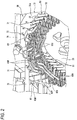
Fig. 2 is a partial perspective view of the rotary electric machine inFig. 1 . - Hereinafter, a rotary electric machine according to an embodiment of the present invention will be described with reference to the accompanying drawings.
- As shown in
Figs. 1 and2 , a rotary electric machine 1 includes arotor 20, astator 30, and acase 40 accommodating therotor 20 and thestator 30. - The
stator 30 includes astator core 31, and astator coil 50 attached to thestator core 31. A plurality ofteeth 32 are provided at equal intervals in a peripheral direction on an inner peripheral portion of thestator core 31, and thestator coil 50 is wound around slots formed between theadjacent teeth 32. - The
stator coil 50 is composed of a plurality ofsegment coils 51 having a substantially U shape. Thestator coil 50 includes coils of a plurality of phases (U phase, V phase, and W phase), and the coils of the plurality of phases are connected by a neutralpoint bus bar 60. That is, one end portions of the coils of respective phases are connected to the neutralpoint bus bar 60. The other end portions of the coils of the respective phases are connected tobus bars bus bar unit 61 which supplies electric power to thestator coil 50. Besides, inFig. 2 ,reference numerals - The neutral
point bus bar 60 is disposed at an uppermost portion of acoil end 52 protruding in the axial direction from oneend surface 31a of thestator core 31. - A
cooling pipe 70 for cooling thestator coil 50 is provided inside thecase 40. Thecooling pipe 70 extends in the axial direction around an upper portion of thestator core 31. Thecooling pipe 70 may be disposed at a plurality of positions in a peripheral direction of thestator core 31.Fig. 2 shows twocooling pipes 70. Besides, in the following description, thecooling pipe 70 disposed at an uppermost portion will be described. - The
cooling pipe 70 includes a firstrefrigerant supply hole 71 for discharging a refrigerant R toward thecoil end 52, a secondrefrigerant supply hole 72 for discharging the refrigerant R toward the neutralpoint bus bar 60, and a thirdrefrigerant supply hole 73 for discharging the refrigerant R toward an outerperipheral surface 31b of thestator core 31. The firstrefrigerant supply hole 71, the secondrefrigerant supply hole 72, and the thirdrefrigerant supply hole 73 are spaced apart from each other in an axial direction of thecooling pipe 70, and are provided so as to face an upper portion of thecoil end 52, an upper portion of the neutralpoint bus bar 60, and an upper portion of the outerperipheral surface 31b of thestator core 31, respectively. - Since the
cooling pipe 70 includes the firstrefrigerant supply hole 71 for discharging the refrigerant R toward thecoil end 52, the secondrefrigerant supply hole 72 for discharging the refrigerant R toward the neutralpoint bus bar 60, and the thirdrefrigerant supply hole 73 for discharging the refrigerant R toward the outerperipheral surface 31b of thestator core 31, thecoil end 52, the neutralpoint bus bar 60 and thestator core 31 can be simultaneously cooled by asingle cooling pipe 70. Particularly, since the neutralpoint bus bar 60 tends to become high temperature, the neutralpoint bus bar 60 can be cooled directly to suppress heat generation of the neutralpoint bus bar 60. Accordingly, since unlike the related art, it is unnecessary to hold the temperature sensor on the neutralpoint bus bar 60, time and labor for performing a special process for holding the temperature sensor in the neutralpoint bus bar 60 can be saved. - Since the neutral
point bus bar 60 is disposed at the uppermost portion of thecoil end 52, direct cooling of the neutralpoint bus bar 60 by the refrigerant R cannot be expected only by supplying the refrigerant R to thecoil end 52 as in the related art. However, by discharging the refrigerant R from thecooling pipe 70 toward the neutralpoint bus bar 60, the neutralpoint bus bar 60 can be directly cooled by the refrigerant R, and the heat generation of the neutralpoint bus bar 60 can be reliably suppressed. Accordingly, a heat requirement can be satisfied without measuring a temperature of a neutral point of thestator coil 50. - In
Fig. 2 , the firstrefrigerant supply holes 71 are provided at two positions in the peripheral direction of thecooling pipe 70. Accordingly, the refrigerant R is supplied to a wide range of thecoil end 52, so that thecoil end 52 can be effectively cooled. Meanwhile, the secondrefrigerant supply hole 72 discharges the refrigerant R at a substantially pinpoint toward the neutralpoint bus bar 60. Accordingly, the neutralpoint bus bar 60 can be reliably cooled by the refrigerant R. - The second
refrigerant supply hole 72 preferably discharges the refrigerant R toward an uppermost portion of the neutralpoint bus bar 60. Accordingly, the refrigerant can be spread throughout the neutralpoint bus bar 60 using gravity, and the neutralpoint bus bar 60 can be effectively cooled. - The above-described embodiment may be appropriately modified, improved, or the like.
- For example, the
cooling pipe 70 may be a single continuous pipe or a plurality of pipes connected in parallel. - In addition, the first
refrigerant supply hole 71, the secondrefrigerant supply hole 72, and the thirdrefrigerant supply hole 73 may be provided in one position, or may be provided in a plurality of positions in the peripheral direction of thecooling pipe 70. - In the above-described embodiment, the third
refrigerant supply hole 73 is provided in thecooling pipe 70, but the thirdrefrigerant supply hole 73 may be provided in a cooling pipe separate from thecooling pipe 70 including the firstrefrigerant supply hole 71 and the secondrefrigerant supply hole 72. - At least the following matters are described in the present specification. Although the corresponding elements or the like in the above-described embodiment are shown in parentheses, the present invention is not limited thereto.
- (1) A rotary electric machine (rotary electric machine 1) includes:
- a rotor (rotor 20);
- a stator (stator 30) including a stator core (stator core 31) and a stator coil (stator coil 50) attached to the stator core, the stator being disposed to be opposed to the rotor; and
- a case (case 40) accommodating the rotor and the stator,
- wherein in the stator coil, coils of a plurality of phases are connected by a neutral point bus bar (neutral point bus bar 60),
- wherein the neutral point bus bar is provided at a coil end (coil end 52) protruding in an axial direction from one end surface (one
end surface 31a) of the stator core, - wherein a cooling pipe (cooling pipe 70) for cooling the stator coil is provided inside the case, and
- wherein the cooling pipe includes a first refrigerant supply hole (first refrigerant supply hole 71) for discharging a refrigerant (refrigerant R) toward the coil end and a second refrigerant supply hole (second refrigerant supply hole 72) for discharging the refrigerant toward the neutral point bus bar.
- (2) In the rotary electric machine according to (1),
the cooling pipe includes a third refrigerant supply hole (third refrigerant supply hole 73) for discharging the refrigerant to an outer peripheral surface (outerperipheral surface 31b) of the stator core.
According to (2), since the cooling pipe includes the third refrigerant supply hole for discharging the refrigerant to the outer peripheral surface of the stator core, in addition to the coil end and the neutral point bus bar, the stator core can also be cooled by a single cooling pipe. - (3) In the rotary electric machine according to (1) or (2),
the neutral point bus bar is disposed at an uppermost portion of the coil end.
According to (3), since the neutral point bus bar is disposed at the uppermost portion of the coil end, direct cooling of the neutral point bus bar with the refrigerant cannot be expected only by supplying the refrigerant to the coil end. However, by discharging the refrigerant from the cooling pipe toward the neutral point bus bar, the neutral point bus bar can be directly cooled by the refrigerant, and the heat generation of the neutral point bus bar can be reliably suppressed. - (4) In the rotary electric machine according to (3),
the second refrigerant supply hole discharges the refrigerant to an uppermost portion of the neutral point bus bar.
According to (4), the second refrigerant supply hole discharges the refrigerant to the uppermost portion of the neutral point bus bar, so that the refrigerant can be spread throughout the neutral point bus bar using gravity, and the neutral point bus bar can be effectively cooled.
Claims (4)
- A rotary electric (1) machine comprising:a rotor (20);a stator (30) including a stator core (31) and a stator coil (50) attached to the stator core (31), the stator (30) being disposed to be opposed to the rotor (20); anda case (40) accommodating the rotor (20) and the stator (30),wherein in the stator coil (50), coils of a plurality of phases are connected by a neutral point bus bar (60),wherein the neutral point bus bar (60) is provided at a coil end (52) protruding in an axial direction from one end surface (31a) of the stator core (31),wherein a cooling pipe (70) for cooling the stator coil (50) is provided inside the case (40), andwherein the cooling pipe (70) includes a first refrigerant supply hole (71) for discharging a refrigerant (R) toward the coil end (52) and a second refrigerant supply hole (72) for discharging the refrigerant (R) toward the neutral point bus bar (60).
- The rotary electric machine (1) according to claim 1,
wherein the cooling pipe (70) includes a third refrigerant supply hole (73) for discharging the refrigerant (R) to an outer peripheral surface (31b) of the stator core (31). - The rotary electric machine (1) according to claim 1 or 2,
wherein the neutral point bus bar (60) is disposed at an uppermost portion of the coil end (52). - The rotary electric machine (1) according to claim 3,
wherein the second refrigerant supply hole (72) discharges the refrigerant (R) to an uppermost portion of the neutral point bus bar (60).
Applications Claiming Priority (1)
| Application Number | Priority Date | Filing Date | Title |
|---|---|---|---|
| JP2018062561A JP2019176626A (en) | 2018-03-28 | 2018-03-28 | Rotary electric machine |
Publications (1)
| Publication Number | Publication Date |
|---|---|
| EP3547508A1 true EP3547508A1 (en) | 2019-10-02 |
Family
ID=65995523
Family Applications (1)
| Application Number | Title | Priority Date | Filing Date |
|---|---|---|---|
| EP19165471.4A Withdrawn EP3547508A1 (en) | 2018-03-28 | 2019-03-27 | Rotary electric machine |
Country Status (4)
| Country | Link |
|---|---|
| US (1) | US20190305639A1 (en) |
| EP (1) | EP3547508A1 (en) |
| JP (1) | JP2019176626A (en) |
| CN (1) | CN110323855A (en) |
Families Citing this family (11)
| Publication number | Priority date | Publication date | Assignee | Title |
|---|---|---|---|---|
| JP6952757B2 (en) * | 2019-12-13 | 2021-10-20 | 三菱電機株式会社 | Rotating machine |
| JP7456192B2 (en) * | 2020-02-28 | 2024-03-27 | ニデック株式会社 | drive device |
| EP4304056A4 (en) * | 2021-03-02 | 2024-08-28 | Panasonic Intellectual Property Management Co., Ltd. | STATOR AND MOTOR EQUIPPED WITH IT |
| US12244197B2 (en) * | 2021-07-14 | 2025-03-04 | Borgwarner Inc. | Stator with outer diameter bus bar connection |
| US20230081217A1 (en) * | 2021-09-10 | 2023-03-16 | Hyundai Motor Company | Structure for injecting cooling oil |
| DE102022107407B4 (en) * | 2022-03-29 | 2024-07-04 | Schaeffler Technologies AG & Co. KG | stator |
| DE102022128307B4 (en) | 2022-10-26 | 2025-07-31 | Schaeffler Technologies AG & Co. KG | stator |
| JP7848669B2 (en) * | 2022-11-29 | 2026-04-21 | トヨタ自動車株式会社 | motor |
| DE102023100964A1 (en) | 2023-01-17 | 2024-07-18 | Schaeffler Technologies AG & Co. KG | Stator, method for producing a stator and kit-of-parts |
| JP7796692B2 (en) * | 2023-04-25 | 2026-01-09 | 本田技研工業株式会社 | Motor cooling device |
| DE102024208554A1 (en) | 2024-09-09 | 2026-03-12 | Volkswagen Aktiengesellschaft | Electric machine and motor vehicle with an electric machine |
Citations (6)
| Publication number | Priority date | Publication date | Assignee | Title |
|---|---|---|---|---|
| JP2004215358A (en) * | 2002-12-27 | 2004-07-29 | Toyota Motor Corp | Multi-phase motor device |
| JP2011217438A (en) * | 2010-03-31 | 2011-10-27 | Toyota Motor Corp | Cooling system for rotating electric machine |
| US20160020658A1 (en) * | 2014-07-18 | 2016-01-21 | Denso Corporation | Stator of Rotating Electric Machine |
| JP2016123155A (en) | 2014-12-24 | 2016-07-07 | トヨタ自動車株式会社 | Stator for rotary electric machine |
| JP2017052387A (en) * | 2015-09-09 | 2017-03-16 | トヨタ自動車株式会社 | Refrigerant supply device |
| JP2017225269A (en) * | 2016-06-16 | 2017-12-21 | アイシン精機株式会社 | Rotating electric machine |
Family Cites Families (5)
| Publication number | Priority date | Publication date | Assignee | Title |
|---|---|---|---|---|
| US5196752A (en) * | 1991-10-31 | 1993-03-23 | Rem Technologies, Inc. | System for supporting conductors for use in a dynamoelectric machine |
| JP5545180B2 (en) * | 2010-11-11 | 2014-07-09 | トヨタ自動車株式会社 | Rotating electric machine |
| US9689281B2 (en) * | 2011-12-22 | 2017-06-27 | Nanjing Tica Air-Conditioning Co., Ltd. | Hermetic motor cooling for high temperature organic Rankine cycle system |
| JP2013172486A (en) * | 2012-02-17 | 2013-09-02 | Aisin Aw Co Ltd | Rotary electric machine |
| JP6237518B2 (en) * | 2014-07-18 | 2017-11-29 | 株式会社デンソー | Rotating electric machine stator |
-
2018
- 2018-03-28 JP JP2018062561A patent/JP2019176626A/en active Pending
-
2019
- 2019-03-27 EP EP19165471.4A patent/EP3547508A1/en not_active Withdrawn
- 2019-03-27 US US16/366,465 patent/US20190305639A1/en not_active Abandoned
- 2019-03-27 CN CN201910240407.4A patent/CN110323855A/en not_active Withdrawn
Patent Citations (6)
| Publication number | Priority date | Publication date | Assignee | Title |
|---|---|---|---|---|
| JP2004215358A (en) * | 2002-12-27 | 2004-07-29 | Toyota Motor Corp | Multi-phase motor device |
| JP2011217438A (en) * | 2010-03-31 | 2011-10-27 | Toyota Motor Corp | Cooling system for rotating electric machine |
| US20160020658A1 (en) * | 2014-07-18 | 2016-01-21 | Denso Corporation | Stator of Rotating Electric Machine |
| JP2016123155A (en) | 2014-12-24 | 2016-07-07 | トヨタ自動車株式会社 | Stator for rotary electric machine |
| JP2017052387A (en) * | 2015-09-09 | 2017-03-16 | トヨタ自動車株式会社 | Refrigerant supply device |
| JP2017225269A (en) * | 2016-06-16 | 2017-12-21 | アイシン精機株式会社 | Rotating electric machine |
Also Published As
| Publication number | Publication date |
|---|---|
| JP2019176626A (en) | 2019-10-10 |
| US20190305639A1 (en) | 2019-10-03 |
| CN110323855A (en) | 2019-10-11 |
Similar Documents
| Publication | Publication Date | Title |
|---|---|---|
| EP3547508A1 (en) | Rotary electric machine | |
| CN110546862B (en) | Bus bar unit and motor having the same | |
| US9079603B2 (en) | Motor for an electric power steering apparatus | |
| CN110476331B (en) | Bus bar unit and motor having the same | |
| JP6237518B2 (en) | Rotating electric machine stator | |
| US20130221889A1 (en) | Multi-phase switched reluctance motor apparatus and control method thereof | |
| JP5335265B2 (en) | Electric motor | |
| US20110018376A1 (en) | Busbar terminal, busbar unit, and motor | |
| EP3410569B1 (en) | Winding configuration of an electric motor | |
| US20160190886A1 (en) | Rotating electric machine | |
| US20130154429A1 (en) | Active part of an electrical machine having inclined coils in the winding head area | |
| US20160322875A1 (en) | Three-phase motor | |
| JP2013223293A5 (en) | ||
| US20210359562A1 (en) | Stator and manufacturing method of the same | |
| US10348149B2 (en) | Stator for rotating electric machine and rotating electric machine including the stator | |
| JP2019221113A (en) | Stator and rotary electric machine | |
| US4604541A (en) | Split stator armature winding | |
| CN111682675A (en) | Electronically commutated motor | |
| US12500485B2 (en) | Stator and rotary electric machine using same | |
| JP2019068572A (en) | Motor and stator | |
| JP2012244839A (en) | Stator for rotating electric machine | |
| US12348101B2 (en) | Stator comprising an interconnector | |
| JP7593122B2 (en) | Method for manufacturing a stator and a rotating electric machine | |
| JP6183326B2 (en) | Electric motor stator, electric motor, and air conditioner | |
| US20210066988A1 (en) | Electrical connection device for rotating electrical machine |
Legal Events
| Date | Code | Title | Description |
|---|---|---|---|
| PUAI | Public reference made under article 153(3) epc to a published international application that has entered the european phase |
Free format text: ORIGINAL CODE: 0009012 |
|
| STAA | Information on the status of an ep patent application or granted ep patent |
Free format text: STATUS: REQUEST FOR EXAMINATION WAS MADE |
|
| 17P | Request for examination filed |
Effective date: 20190327 |
|
| AK | Designated contracting states |
Kind code of ref document: A1 Designated state(s): AL AT BE BG CH CY CZ DE DK EE ES FI FR GB GR HR HU IE IS IT LI LT LU LV MC MK MT NL NO PL PT RO RS SE SI SK SM TR |
|
| AX | Request for extension of the european patent |
Extension state: BA ME |
|
| STAA | Information on the status of an ep patent application or granted ep patent |
Free format text: STATUS: EXAMINATION IS IN PROGRESS |
|
| 17Q | First examination report despatched |
Effective date: 20200609 |
|
| STAA | Information on the status of an ep patent application or granted ep patent |
Free format text: STATUS: THE APPLICATION HAS BEEN WITHDRAWN |
|
| 18W | Application withdrawn |
Effective date: 20200908 |