EP3547496A2 - Écosystème et bobines de transfert de puissance sans fil fonctionnant sur des niveaux de puissance sensiblement différents - Google Patents
Écosystème et bobines de transfert de puissance sans fil fonctionnant sur des niveaux de puissance sensiblement différents Download PDFInfo
- Publication number
- EP3547496A2 EP3547496A2 EP19165040.7A EP19165040A EP3547496A2 EP 3547496 A2 EP3547496 A2 EP 3547496A2 EP 19165040 A EP19165040 A EP 19165040A EP 3547496 A2 EP3547496 A2 EP 3547496A2
- Authority
- EP
- European Patent Office
- Prior art keywords
- wireless power
- magnetic
- magnetic shield
- conductive region
- power transmitter
- Prior art date
- Legal status (The legal status is an assumption and is not a legal conclusion. Google has not performed a legal analysis and makes no representation as to the accuracy of the status listed.)
- Pending
Links
- 230000005291 magnetic effect Effects 0.000 claims abstract description 128
- 230000035699 permeability Effects 0.000 claims abstract description 24
- 230000005540 biological transmission Effects 0.000 claims abstract description 13
- 230000008878 coupling Effects 0.000 claims description 23
- 238000010168 coupling process Methods 0.000 claims description 23
- 238000005859 coupling reaction Methods 0.000 claims description 23
- 238000001514 detection method Methods 0.000 claims description 6
- 230000002401 inhibitory effect Effects 0.000 claims description 2
- 239000000463 material Substances 0.000 description 11
- 238000000034 method Methods 0.000 description 9
- 230000001105 regulatory effect Effects 0.000 description 8
- 239000004020 conductor Substances 0.000 description 7
- 238000004891 communication Methods 0.000 description 5
- 230000001939 inductive effect Effects 0.000 description 4
- 238000004590 computer program Methods 0.000 description 3
- 230000006870 function Effects 0.000 description 3
- 230000002829 reductive effect Effects 0.000 description 3
- 239000000758 substrate Substances 0.000 description 3
- XEEYBQQBJWHFJM-UHFFFAOYSA-N Iron Chemical compound [Fe] XEEYBQQBJWHFJM-UHFFFAOYSA-N 0.000 description 2
- PXHVJJICTQNCMI-UHFFFAOYSA-N Nickel Chemical compound [Ni] PXHVJJICTQNCMI-UHFFFAOYSA-N 0.000 description 2
- 239000012141 concentrate Substances 0.000 description 2
- 238000010586 diagram Methods 0.000 description 2
- 238000005516 engineering process Methods 0.000 description 2
- 230000004907 flux Effects 0.000 description 2
- 230000000670 limiting effect Effects 0.000 description 2
- 229910052751 metal Inorganic materials 0.000 description 2
- 239000002184 metal Substances 0.000 description 2
- 230000004044 response Effects 0.000 description 2
- 239000004065 semiconductor Substances 0.000 description 2
- 229910000859 α-Fe Inorganic materials 0.000 description 2
- RYGMFSIKBFXOCR-UHFFFAOYSA-N Copper Chemical compound [Cu] RYGMFSIKBFXOCR-UHFFFAOYSA-N 0.000 description 1
- 229910000831 Steel Inorganic materials 0.000 description 1
- 230000004913 activation Effects 0.000 description 1
- 239000003570 air Substances 0.000 description 1
- 229910045601 alloy Inorganic materials 0.000 description 1
- 239000000956 alloy Substances 0.000 description 1
- 229910052782 aluminium Inorganic materials 0.000 description 1
- XAGFODPZIPBFFR-UHFFFAOYSA-N aluminium Chemical compound [Al] XAGFODPZIPBFFR-UHFFFAOYSA-N 0.000 description 1
- 230000033228 biological regulation Effects 0.000 description 1
- 230000008859 change Effects 0.000 description 1
- 150000001875 compounds Chemical class 0.000 description 1
- 229910052802 copper Inorganic materials 0.000 description 1
- 239000010949 copper Substances 0.000 description 1
- 230000005674 electromagnetic induction Effects 0.000 description 1
- 239000003302 ferromagnetic material Substances 0.000 description 1
- 239000011521 glass Substances 0.000 description 1
- 238000010438 heat treatment Methods 0.000 description 1
- 230000006698 induction Effects 0.000 description 1
- 229910052742 iron Inorganic materials 0.000 description 1
- 230000007246 mechanism Effects 0.000 description 1
- 229910052759 nickel Inorganic materials 0.000 description 1
- 230000036961 partial effect Effects 0.000 description 1
- 239000004033 plastic Substances 0.000 description 1
- 229920003023 plastic Polymers 0.000 description 1
- 229920000642 polymer Polymers 0.000 description 1
- 230000009467 reduction Effects 0.000 description 1
- 239000007787 solid Substances 0.000 description 1
- 239000010959 steel Substances 0.000 description 1
- 230000001360 synchronised effect Effects 0.000 description 1
- 230000002123 temporal effect Effects 0.000 description 1
- 239000002023 wood Substances 0.000 description 1
Images


Classifications
-
- H—ELECTRICITY
- H02—GENERATION; CONVERSION OR DISTRIBUTION OF ELECTRIC POWER
- H02J—CIRCUIT ARRANGEMENTS OR SYSTEMS FOR SUPPLYING OR DISTRIBUTING ELECTRIC POWER; SYSTEMS FOR STORING ELECTRIC ENERGY
- H02J50/00—Circuit arrangements or systems for wireless supply or distribution of electric power
- H02J50/10—Circuit arrangements or systems for wireless supply or distribution of electric power using inductive coupling
-
- H—ELECTRICITY
- H01—ELECTRIC ELEMENTS
- H01F—MAGNETS; INDUCTANCES; TRANSFORMERS; SELECTION OF MATERIALS FOR THEIR MAGNETIC PROPERTIES
- H01F27/00—Details of transformers or inductances, in general
- H01F27/34—Special means for preventing or reducing unwanted electric or magnetic effects, e.g. no-load losses, reactive currents, harmonics, oscillations, leakage fields
- H01F27/36—Electric or magnetic shields or screens
- H01F27/366—Electric or magnetic shields or screens made of ferromagnetic material
-
- H—ELECTRICITY
- H01—ELECTRIC ELEMENTS
- H01F—MAGNETS; INDUCTANCES; TRANSFORMERS; SELECTION OF MATERIALS FOR THEIR MAGNETIC PROPERTIES
- H01F38/00—Adaptations of transformers or inductances for specific applications or functions
- H01F38/14—Inductive couplings
-
- H—ELECTRICITY
- H02—GENERATION; CONVERSION OR DISTRIBUTION OF ELECTRIC POWER
- H02J—CIRCUIT ARRANGEMENTS OR SYSTEMS FOR SUPPLYING OR DISTRIBUTING ELECTRIC POWER; SYSTEMS FOR STORING ELECTRIC ENERGY
- H02J50/00—Circuit arrangements or systems for wireless supply or distribution of electric power
-
- H—ELECTRICITY
- H02—GENERATION; CONVERSION OR DISTRIBUTION OF ELECTRIC POWER
- H02J—CIRCUIT ARRANGEMENTS OR SYSTEMS FOR SUPPLYING OR DISTRIBUTING ELECTRIC POWER; SYSTEMS FOR STORING ELECTRIC ENERGY
- H02J50/00—Circuit arrangements or systems for wireless supply or distribution of electric power
- H02J50/10—Circuit arrangements or systems for wireless supply or distribution of electric power using inductive coupling
- H02J50/12—Circuit arrangements or systems for wireless supply or distribution of electric power using inductive coupling of the resonant type
-
- H—ELECTRICITY
- H02—GENERATION; CONVERSION OR DISTRIBUTION OF ELECTRIC POWER
- H02J—CIRCUIT ARRANGEMENTS OR SYSTEMS FOR SUPPLYING OR DISTRIBUTING ELECTRIC POWER; SYSTEMS FOR STORING ELECTRIC ENERGY
- H02J50/00—Circuit arrangements or systems for wireless supply or distribution of electric power
- H02J50/40—Circuit arrangements or systems for wireless supply or distribution of electric power using two or more transmitting or receiving devices
- H02J50/402—Circuit arrangements or systems for wireless supply or distribution of electric power using two or more transmitting or receiving devices the two or more transmitting or the two or more receiving devices being integrated in the same unit, e.g. power mats with several coils or antennas with several sub-antennas
-
- H—ELECTRICITY
- H02—GENERATION; CONVERSION OR DISTRIBUTION OF ELECTRIC POWER
- H02J—CIRCUIT ARRANGEMENTS OR SYSTEMS FOR SUPPLYING OR DISTRIBUTING ELECTRIC POWER; SYSTEMS FOR STORING ELECTRIC ENERGY
- H02J50/00—Circuit arrangements or systems for wireless supply or distribution of electric power
- H02J50/60—Circuit arrangements or systems for wireless supply or distribution of electric power responsive to the presence of foreign objects, e.g. detection of living beings
-
- H—ELECTRICITY
- H02—GENERATION; CONVERSION OR DISTRIBUTION OF ELECTRIC POWER
- H02J—CIRCUIT ARRANGEMENTS OR SYSTEMS FOR SUPPLYING OR DISTRIBUTING ELECTRIC POWER; SYSTEMS FOR STORING ELECTRIC ENERGY
- H02J50/00—Circuit arrangements or systems for wireless supply or distribution of electric power
- H02J50/70—Circuit arrangements or systems for wireless supply or distribution of electric power involving the reduction of electric, magnetic or electromagnetic leakage fields
-
- H—ELECTRICITY
- H02—GENERATION; CONVERSION OR DISTRIBUTION OF ELECTRIC POWER
- H02J—CIRCUIT ARRANGEMENTS OR SYSTEMS FOR SUPPLYING OR DISTRIBUTING ELECTRIC POWER; SYSTEMS FOR STORING ELECTRIC ENERGY
- H02J50/00—Circuit arrangements or systems for wireless supply or distribution of electric power
- H02J50/80—Circuit arrangements or systems for wireless supply or distribution of electric power involving the exchange of data, concerning supply or distribution of electric power, between transmitting devices and receiving devices
-
- H—ELECTRICITY
- H04—ELECTRIC COMMUNICATION TECHNIQUE
- H04B—TRANSMISSION
- H04B5/00—Near-field transmission systems, e.g. inductive or capacitive transmission systems
- H04B5/20—Near-field transmission systems, e.g. inductive or capacitive transmission systems characterised by the transmission technique; characterised by the transmission medium
- H04B5/24—Inductive coupling
- H04B5/26—Inductive coupling using coils
- H04B5/263—Multiple coils at either side
Definitions
- the techniques described herein relate generally to wireless power delivery, and particularly to apparatus and systems capable of sending and/or receiving power wirelessly at different power levels by different coils.
- WPTS Wireless Power Transfer Systems
- MI magnetic induction
- MR magnetic resonance
- MI magnetic induction
- MR magnetic resonance
- Both types of systems include a wireless power transmitter and a wireless power receiver.
- Such systems can be used to power or charge mobile devices such as smartphones or tablet computers, among other applications.
- Inductive WPTS typically operate in an allocated frequency range of several hundred kilohertz using frequency variation as a power flow control mechanism.
- MR WPTS typically operate on a single resonant frequency using input voltage regulation to regulate output power. In typical applications, MR WPTS operate at a frequency of 6.78 MHz.
- Some embodiments relate to a wireless power transmitter apparatus, comprising: a first transmit coil; a first magnetic shield for the first transmit coil; a second transmit coil; a second magnetic shield for the second transmit coil; and a gap separating the first magnetic shield and the second magnetic shield, the gap having a magnetic permeability lower than that of the first magnetic shield and the second magnetic shield.
- the first transmit coil may surround the second transmit coil.
- the first transmit coil may be disposed on the first magnetic shield and the second transmit coil may be disposed on the second magnetic shield.
- the gap may have a magnetic permeability less than 10% of that of the first magnetic shield.
- the gap may have a magnetic permeability less than 1% of that of the first magnetic shield.
- the wireless power transmitter apparatus may further comprise a conductive region proximate the gap to reduce magnetic coupling between the first and second magnetic shields.
- the conductive region may be below the gap.
- the conductive region may be at least partially within the gap.
- the first magnetic shield may have an annular shape in top view.
- the second magnetic shield may have a circular shape in top view.
- the first magnetic shield, the second magnetic shield or both the first and second magnetic shields may include at least one magnetic concentrator.
- the at least one magnetic concentrator may extend into an interior of the second transmit coil.
- the at least one magnetic concentrator may extend around an exterior of the second transmit coil.
- the first magnetic shield and the second magnetic shield may have different values of magnetic permeability.
- Some embodiments relate to a wireless power receiver apparatus, comprising: a receive coil; and a conductive region within an area defined by the receive coil, the conductive region sized and positioned to inhibit operation of a wireless power transmitter not configured for wireless power transmission to the receive coil.
- the conductive region may be below the receive coil.
- the conductive region may be concentric with the receive coil.
- the conductive region may have a circular shape in top view.
- the wireless power receiver apparatus may further comprise a magnetic shield under the receive coil.
- the conductive region may be separated from the magnetic shield by a gap.
- the conductive region may be sized and positioned to trigger a foreign object detection operation by the wireless power transmitter inhibiting wireless power transfer by the wireless power transmitter.
- a wireless power transmitter may have a first transmit coil for transmitting relatively high levels of power and a second transmit coil for transmitting lower levels of power.
- a wireless power transmitter may have a first, relatively large coil for transferring relatively high levels of power to devices that are capable of being powered or charged by relatively high power levels, such as a laptop or tablet computer, for example.
- the wireless power transmitter may have a second, relatively small coil for transferring relatively low levels of power to devices that accept lower power levels, such as a smartphone or wearable device, for example.
- Smaller coils may be associated with physically smaller electronic devices which tend to consume less power. Transferring higher power levels by means of small coils can be inefficient. As physically larger electronics devices require more power, larger coils may be more appropriate to facilitate efficient wireless power transfer. Transferring electrical energy wirelessly between two coils of substantially different sizes can also be inefficient, hence it may be more efficient to have corresponding coil dimensions between transmitting and receiving devices. It can also be desirable when designing a charging device to achieve its compatibility with a wide range of mobile devices, i.e., mobile phones, watches, tablet computers, notebooks, etc.
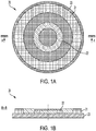
- FIGS. 1A and 1B show a top view and cross-sectional view, respectively, of an example of a wireless power transmitter 20 having a plurality of coils that may transmit power wirelessly at different power levels.
- Wireless power transmitter 20 has a first transmit coil 21 and a second transmit coil 22.
- the transmit coils 21 and 22 are each wound in a circular shape when viewed from the top view of FIG. 1A .
- the shape of the transmit coils 21 and 22 is not limited to a circular shape.
- the transmit coils 21, 22 may have any suitable number of one or more turns.
- the transmit coils 21, 22 may be formed of any suitable conductor type such as wires or conductive traces, for example.
- the first transmit coil 21 is larger than the second transmit coil 22 and surrounds the second transmit coil 22.
- the transmit coils 21 and 22 may be co-planar, as illustrated in FIG. 1B .
- the transmit coils 21 and 22 may be concentric, as illustrated in FIG. 1A .
- the techniques described herein are not limited in these respects, as in some embodiments the coils may have a different relative size and/or positions.
- the first transmit coil 21 may be capable of transmitting relatively high levels of power and the second transmit coil 22 may be capable of transmitting relatively low levels of power (e.g., lower than that of the first coil).
- Examples of power levels capable of being transmitted by the first and second transmit coils 21 and 22 are 5W, 15W, 60W, and 100W, with the first transmit coil 21 transmitting a higher power than the second transmit coil 22 transmits. However, this is merely by way of example, as any suitable power levels may be transmitted by the first and second transmit coils 21, 22.
- the first and second transmit coils 21, 22 may be disposed on a magnetic shield 23.
- the magnetic shield 23 may concentrate magnetic flux within the magnetic shield 23 and reduce the strength of the magnetic field below the magnetic shield which may shield electronics (not shown) below the magnetic shield 23 from the magnetic field produced by transmit coils 21, 22.
- the magnetic shield 23 may be formed of a ferromagnetic material.
- the magnetic shield 23 may have a relatively high magnetic permeability, such as greater than 10, greater than 100 or greater than 1000.
- the magnetic shield 23 may be formed of a suitable material such as ferrite, iron, steel, or nickel, or alloys or powdered compounds made of mentioned, or similar materials, by way of example. However, the structures described herein are not limited as to particular materials.
- the magnetic shield 23 may be formed of a flexible ferrite sheet.
- the transmit coils 21 and 22 may be formed of a flexible printed circuit. Accordingly, in some embodiments the structure may have a low profile and/or may be flexible.
- first and second transmit coils 21, 22 may operate on different power levels, use different frequencies and/or different communication protocols, coupling between the first and second transmit coils 21, 22 may be undesirable.
- only one of the first and second transmit coils 21, 22 may transmit at a time.
- High-voltage commutating switches may be used to disengage the coil not being driven.
- the coupling between the first and second transmit coils 21, 22 can be reduced by using the structures and/or techniques described herein.
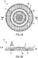
- FIGS. 2A and 2B show a top view and a cross-sectional view, respectively, of an example of a wireless power transmitter 30 with a gap 24 of low magnetic permeability separating magnetic shields 23A and 23B.
- the gap 24 is magnetically inert.
- Introducing a gap 24 of low magnetic permeability between magnetic shields 23A and 23B reduces the magnetic coupling between the transmit coils 21, 22.
- the transmit coils 21, 22 may be modeled as a transformer with a coupling coefficient k.
- the coupling coefficient K relates the amount of signal that will be induced in one coil 21 or 22 when an alternating current flows in the other coil 21 or 22.
- a lower coupling coefficient K results in a lower induced signal, while a higher coupling coefficient K results in a higher induced signal.
- the coupling coefficient K is a parameter that is well known in the art and will not be detailed herein.
- the gap 24 may have an annular shape when viewed from above.
- the gap 24 need not have an annular shape, as the gap 24 may have any other suitable shape when viewed from above.
- the inner and/or outer boundaries of the gap 24 may form a polygon shape when viewed from above, or any other suitable shape.
- the gap 24 may have any suitable width.
- the gap 24 may be sufficiently wide to reduce the coupling coefficient appreciably.
- the width of gap 24 is between 1%-50% of the diameter of the first transmit coil 21 or the second transmit coil 22.
- the structures described herein are not limited as to any particular width of gap 24, as variety of suitable gap widths may be used.
- the gap 24 has a magnetic permeability ⁇ lower than that of the magnetic shield 23A or 23B.
- the gap 24 may have a magnetic permeability less than 10% or less than 1% of that of the magnetic shields 23A and 23B.
- the magnetic shields 23A and 23B may have a magnetic permeability of 1000 and the gap 24 may have a magnetic permeability of less than 10, such as less than 5.
- the gap 24 may be 1.
- the gap 24 may include any suitable material of low magnetic permeability, such as air, glass, wood, plastics, polymers and many other materials.
- the gap may be a vacuum.
- the electrical conductivity of the gap 24 may be low.
- Magnetic shields 23A and 23B may have the same magnetic permeability or may have different values of magnetic permeability. In some embodiments, the magnetic shield 23A may have a higher magnetic permeability than that of the magnetic shield 23B. If the magnetic permeability has different values in the magnetic shields 23A and 23B, the magnetic permeability of the gap 24 may be lower than that of both magnetic shields 23A and 23B.
- the wireless power transmitter 30 may include a plurality of low-power transmit coils 22.
- the high-power transmit coil 21 may surround all of the low-power transmit coils 22.
- the high-power transmit coil 21 need not surround all of the low-power transmit coils 22.
- FIGS. 3A and 3B show a top view and cross-sectional view, respectively, of another example of a magnetic shield 23B having one or more field concentrators.
- the field concentrators may concentrate magnetic flux therein and may reduce coupling between the transmit coils 21, 22.
- the field concentrators may be one or more portions of magnetic shield 23B extending upward on the interior and/or exterior of the transmit coil 22.
- the field concentrators may extend upward to the level of the transmit coil 22 as viewed in the cross section of FIG. 3B.
- FIGS. 3A and 3B show a field concentrator 25A on the interior of the transmit coil 22 and a field concentrator 25B on the exterior of the transmit coil 22.
- a magnetic shield need not have field concentrators on both the interior and exterior of transmit coil 22.
- a magnetic shield may have only field concentrator 25A or only field concentrator 25B.
- the magnetic field concentrators may be formed monolithically with the magnetic shield, 23B, of the same material.
- the magnetic field concentrators may be separate from the magnetic shield 23B and/or may be formed of a different material.
- the field concentrators may have any suitable shape.
- field concentrator 25A may have a circular shape when viewed from above and field concentrator 25B may have an annular shape when viewed from above.
- the structures described herein are not limited to particular shapes, as the field concentrators may have inner and/or outer boundaries that take any suitable shape when viewed from above, such as a polygon shape or another shape.
- the magnetic coupling between the transmit coils 21, 22 may be further reduced by positioning an electrically conductive region within or proximate the gap 24.
- an electrically conductive region within or proximate the gap 24.
- transmit coil 21 or 22 is driven with an alternating current, a first magnetic field is produced in and near the gap that induces eddy currents in the electrically conductive region.
- the eddy currents in the electrically conductive region produce a second magnetic field opposing the first magnetic field.
- the magnetic coupling between the first and second transmit coils 21, 22 is reduced.
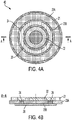
- FIGS. 4A and 4B show a top view and cross-sectional view, respectively, of a wireless power transmitter 40 that includes a conductive region 26.
- Conductive region 26 may be positioned below the magnetic shields 23A and 23B and the gap 24. As shown in FIG. 4B , the conductive region 26 is positioned just below the gap 24, which reduces coupling between the first and second transmit coils 21, 22, as discussed above.
- the conductive region 26 has a circular shape in this example. However, the conductive region may have any suitable shape such as an annular shape, a polygon shape, an elliptical shape, or any other suitable shape.
- the magnetic shields 23A, 23B may be affixed (e.g., adhered) to the conductive region or attached in another manner.
- Conductive region 26 completely covers the gap 24.
- the conductive region may completely cover the gap 24 or may partially cover the gap 24, in the sense of horizontal extent of the conductive region 26 and gap 24.
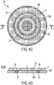
- FIGS. 4C and 4D show an example of a conductive region 27 that does not completely cover the gap 24.
- FIGS. 4C and 4D show a top view and cross-sectional view, respectively, of a wireless power transmitter 50 in which a conductive region 27 is within the gap 24.
- conductive region 27 is completely within the gap 24.
- the conductive region 27 may be completely within the gap 24 or partially within the gap 24.
- the conductive region has an annular shape.
- the conductive region 27 may be positioned closer to the transmit coil 21 than to the transmit coil 22.
- the conductive region 27 may be positioned closer to the transmit coil 22 than to the transmit coil 21.
- the conductive region 27 may be positioned equidistant from the transmit coils 21 and 22.
- the conductive region may have a low aspect ratio, as illustrated in FIG. 4D , in which the conductive region 27 is wider than it is tall (e.g., by a factor of 2:1 or greater). In some embodiments, the conductive region 27 may have a high aspect ratio in which the conductive region 27 is taller than it is wide (e.g., by a factor of 2:1 or greater).
- a wireless power transmitter may include both a conductive region 26, as shown in FIGS. 4A and 4B , and a conductive region 27, as shown in FIGS. 4C and 4D .
- the conductive region may be formed on a substrate (not shown) or otherwise disposed in the gap.
- the magnetic shields 23A and 23B may be formed on a substrate (not shown) in this embodiment and any of the preceding embodiments.
- the conductive regions described herein may be formed of any suitable conductive material, such as a metal (e.g., copper, aluminum, etc.) or semiconductor material, for example.
- a metal e.g., copper, aluminum, etc.
- semiconductor material for example.
- the conductive regions described herein are not limited as to particular materials.
- Table 1 shows the coil-to-coil coupling coefficients K for a geometry without magnetic concentrators in three different transmitter geometry configurations and three different wireless power receiver options.
- the three wireless power receiver options shown are the following.
- the transmitter geometry configurations are as follows.
- Table 2 shows results for the same wireless power receiver options as Table 1, with the following transmitter geometry configurations.
- the transmitter geometry configurations are as follows.
- the experimental results show a reduction coil-to-coil coupling coefficient by a factor of ⁇ 1.5 for the embodiments with a gap and by a factor of about ⁇ 3 for the embodiments with a gap and conductive region.
- the gap 24 may reduce the coupling coefficient K by 20% to 100%.
- the conductive region may further reduce the coupling coefficient K by 50% to 150%.
- a wireless power transmitters configured to transmit low power levels may be activated by the presence of a high-power wireless power receiver.
- low-power legacy wireless power transmitters may not have the capability of detecting whether a wireless power receiver is a low-power wireless power receiver or a high-power wireless power receiver.
- Activation of a low-power wireless power transmitter by the presence of a high-power wireless power receiver may be undesirable as it may produce unintended operation of the wireless power receiver or wireless power transmitter.
- a wireless power receiver may include a conductive region disposed such that when the wireless power receiver is positioned near a wireless power transmitter having a (relatively small) transmit coil 22, the wireless power transmitter will detect the conductive region as a foreign object and prevent or stop wireless power transmission.
- FIGS. 5A and 5B show a top view and a cross-sectional view, respectively, of an example of a wireless power receiver 60 having a conductive region 61.
- Conductive region 61 may be sized and shaped such that a low-power transmit coil of a wireless power transmitter placed in the proximity of conductive region 61 will detect conductive region 61 as a foreign object and inhibit wireless power transfer.
- FIG. 5A illustrates the area 62 of conductive region 61 covered by a low-power receive coil in one example in which the conductive region 61 fully covers area 62.
- conductive region 61 need not fully cover area 62, as in some embodiments less than full coverage of area 62 is sufficient for the transmit coil to detect conductive region 61 as a foreign object. As shown in FIG.
- the conductive region 61 may be circular in a top view. However, the conductive region 61 need not be circular, and may be any suitable shape such as a polygon shape or another shape. As shown in FIG. 5B , the conductive region 61 may be located below the level of the receive coil 121, for example at the level of the magnetic shield 123, to avoid magnetic coupling between the receive coil 121 and the conductive region 61. Conductive region 61 may be formed of any suitable conductive material, such as a metal or semiconductor material, for example. However, the conductive regions described herein are not limited as to particular materials.
- the wireless power receiver also includes a receive coil 121, which may be a high-power receive coil.
- the receive coil 121 may be disposed on a magnetic shield 123.
- the receive coil 121 may be affixed to one side of the magnetic shield 123.
- the magnetic shield 123 may have one or more field concentrators, as discussed above.
- the magnetic shield 123 may be disposed on a substrate (not shown).
- wireless power transmitters and receivers also include additional electronics not described above or shown in the above-described figures. Further description of the electronics and operation of the wireless power transmitters and receivers is provided below.
- FIG. 6 shows a block diagram of a wireless power system 100 including a wireless power transmitter 1 and a wireless power receiver 11.
- the wireless power transmitter 1 has a drive circuit 7a including an inverter 3 that drives a high power transmit coil 21 through a matching network 6.
- the wireless power transmitter 1 may include a regulated voltage source 2 (e.g., a voltage regulator) that provides a regulated DC voltage to the inverter 3.
- the regulated voltage source 2 produces a regulated DC output voltage in response to control stimulus from the controller 5.
- the drive circuit 7a may be a class D or E amplifier that converts the DC voltage at the input of inverter 3 into an AC output voltage to drive the high-power transmit coil 21. Producing an AC output voltage enables wireless power transmission through electromagnetic induction.
- the controller 5 may control a signal generator 9 to drive the inverter 3 with signals of a selected wireless power transmission frequency.
- the inverter 3 may be switched at a frequency between 100 and 205 kHz to transmit power to a wireless power receiver designed to receive wireless power according to the Qi specification for low power Qi receivers and 80-300 kHz for medium power Qi receivers.
- the inverter 3 may be switched at a higher frequency, such as a frequency of greater than 1 MHz, within an ISM band, e.g., 6.765 MHz to 6.795 MHz, to transmit power to a receiver designed to receive wireless power using MR technology.
- Controller 5 may be an analog circuit or a digital circuit. Controller 5 may be programmable, and may command signal generator 9 to produce signals at a desired transmission frequency based on stored program instructions, so that inverter 3 switches at the desired transmission frequency.
- Matching network 6 may facilitate wireless power delivery by presenting a suitable impedance to the inverter 3.
- the matching network(s) may have one or more capacitive or inductive elements or any suitable combination of capacitive and inductive elements.
- the matching network 6 may include one or more capacitive elements, which, when combined with the impedance(s) of the transmit coil 21, presents an impedance to the output of inverter 3 suitable for driving the transmit coil 21.
- the resonant frequency of the matching network 6 may be set equal to or approximately equal to the switching frequency of the inverter 3.
- the transmit coil 21 may be realized by any suitable type of conductors.
- the conductors may be wires, including solid wire or Litz wire, or patterned conductors, such as patterned conductors of a PC board or an integrated circuit.
- the low power transmit coil 22 may have a drive circuit 7b, which may be the same or different from drive circuit 7a.
- Drive circuit 7b may be controlled by controller 5 and signal generator 9 or by a different controller and/or signal generator.
- Drive circuit 7b may receive power from a regulated voltage source which may be the same as regulated voltage source 2 or a different regulated voltage source.
- the AC current in the transmit coil 21 or 22 generates an oscillating magnetic field in accordance with Ampere's law.
- the oscillating magnetic field induces an AC voltage into a receiver coil 121 of the wireless power receiver 11 in accordance with Faraday's law.
- the AC voltage induced in the receiver coil 121 is provided through a matching network 13 to a rectifier 14 that generates an unregulated DC voltage.
- Rectifier 14 may be a synchronous rectifier or may be implemented using diodes.
- the unregulated DC voltage is regulated using a DC/DC converter 15, the output of which may be filtered and provided to a load as output voltage Vout.
- the DC/DC converter 15 can be replaced by a linear regulator or battery charger, or eliminated altogether.
- the wireless power transmitter receiver 1 may have communication circuitry (e.g., within controller 5) for communicating with wireless power receiver 11 either through in-band communication or out of band communication.
- wireless power receiver 11 may have communication circuitry for communicating with a wireless power transmitter 1.
- the wireless power receiver 11 may send feedback information to the wireless power transmitter 1 indicating the power demanded at the wireless power receiver 11, or a change in the power level to be provided.
- the wireless power transmitter 1 may increase or decrease its power output accordingly.
- the wireless power transmitter 1 may control the amount of power transmitted by varying the voltage drive level, the frequency of the signal transmitted or both. Any suitable power control techniques may be used.
- a conductive foreign object 29 enters the field produced by the transmit coil 21 or 22 of the wireless power transmitter 1, the wireless power transmission efficiency may be degraded and/or the conductive foreign object 29 may undergo significant heating.
- Examples of conductive foreign objects 29 include coins, paperclips, and keys, by way of illustration.
- conductive region 61 of wireless power receiver 60 may be detected as a foreign object by some wireless power transmitters.
- the wireless power transmitter 1 may be controlled to perform foreign object detection prior to wireless power transmission.
- Performing foreign object detection allows the wireless power transmitter to determine whether or not to perform wireless power transmission.
- foreign object detection may involve the wireless power transmitter transmitting a signal and determining whether the quality factor or resonance frequency of the system indicates significant loss due to a foreign object.
- Foreign object detection techniques are known and will not be detailed herein. If a foreign object is determined to be present, wireless power transmission can be disabled by the wireless power transmitter. If a foreign object is determined not to be present, wireless power transmission may be enabled.
- a multi-mode wireless power transmitter may be controlled using controller 5, which may be implemented by any suitable type of circuitry.
- the controller 5 may be implemented using hardware or a combination of hardware and software.
- suitable software code can be executed on any suitable processor (e.g., a microprocessor) or collection of processors.
- the one or more controllers can be implemented in numerous ways, such as with dedicated hardware, or with general purpose hardware (e.g., one or more processors) that is programmed using microcode or software to perform the functions recited above.
- one implementation of the embodiments described herein comprises at least one computer-readable storage medium (e.g., RAM, ROM, EEPROM, flash memory or other memory technology, or other tangible, non-transitory computer-readable storage medium) encoded with a computer program (i.e., a plurality of executable instructions) that, when executed on one or more processors, performs the above-discussed functions of one or more embodiments.
- a computer program i.e., a plurality of executable instructions
- the reference to a computer program which, when executed, performs any of the above-discussed functions is not limited to an application program running on a host computer.
- computer program and software are used herein in a generic sense to reference any type of computer code (e.g., application software, firmware, microcode, or any other form of computer instruction) that can be employed to program one or more processors to implement aspects of the techniques discussed herein.
- any type of computer code e.g., application software, firmware, microcode, or any other form of computer instruction
Landscapes
- Engineering & Computer Science (AREA)
- Power Engineering (AREA)
- Computer Networks & Wireless Communication (AREA)
- Physics & Mathematics (AREA)
- Electromagnetism (AREA)
- Signal Processing (AREA)
- Charge And Discharge Circuits For Batteries Or The Like (AREA)
- Near-Field Transmission Systems (AREA)
- Regulation Of General Use Transformers (AREA)
Applications Claiming Priority (2)
| Application Number | Priority Date | Filing Date | Title |
|---|---|---|---|
| US201862647904P | 2018-03-26 | 2018-03-26 | |
| US16/283,677 US10916971B2 (en) | 2018-03-26 | 2019-02-22 | Wireless power transfer ecosystem and coils operating on substantially different power levels |
Publications (2)
| Publication Number | Publication Date |
|---|---|
| EP3547496A2 true EP3547496A2 (fr) | 2019-10-02 |
| EP3547496A3 EP3547496A3 (fr) | 2020-01-08 |
Family
ID=65955137
Family Applications (1)
| Application Number | Title | Priority Date | Filing Date |
|---|---|---|---|
| EP19165040.7A Pending EP3547496A3 (fr) | 2018-03-26 | 2019-03-25 | Écosystème et bobines de transfert de puissance sans fil fonctionnant sur des niveaux de puissance sensiblement différents |
Country Status (4)
| Country | Link |
|---|---|
| US (1) | US10916971B2 (fr) |
| EP (1) | EP3547496A3 (fr) |
| CN (1) | CN110365127B (fr) |
| TW (1) | TWI710195B (fr) |
Families Citing this family (5)
| Publication number | Priority date | Publication date | Assignee | Title |
|---|---|---|---|---|
| JP7287402B2 (ja) * | 2018-09-27 | 2023-06-06 | 株式会社村田製作所 | ワイヤレス給電システム |
| JPWO2020203689A1 (fr) * | 2019-03-29 | 2020-10-08 | ||
| CN111262303A (zh) * | 2020-03-17 | 2020-06-09 | 麦格磁电科技(珠海)有限公司 | 无线充电屏蔽体及其制造方法、无线充电器 |
| CN113452160B (zh) * | 2020-03-26 | 2024-03-29 | 华为技术有限公司 | 一种终端设备及无线充电组件 |
| CN114430201A (zh) * | 2020-10-28 | 2022-05-03 | 致伸科技股份有限公司 | 通用型无线充电装置 |
Family Cites Families (21)
| Publication number | Priority date | Publication date | Assignee | Title |
|---|---|---|---|---|
| US7522878B2 (en) | 1999-06-21 | 2009-04-21 | Access Business Group International Llc | Adaptive inductive power supply with communication |
| WO2009114671A1 (fr) | 2008-03-13 | 2009-09-17 | Access Business Group International Llc | Système d’alimentation de puissance inductive à pluralité de primaires de bobine |
| JP4725604B2 (ja) | 2008-06-25 | 2011-07-13 | セイコーエプソン株式会社 | 送電制御装置、送電装置、受電制御装置、受電装置及び電子機器 |
| AU2010234396A1 (en) | 2009-04-08 | 2011-10-27 | Access Business Group International Llc | Selectable coil array |
| KR20130099071A (ko) | 2010-08-25 | 2013-09-05 | 액세스 비지니스 그룹 인터내셔날 엘엘씨 | 무선 전원 공급 시스템 및 다층 심 조립체 |
| TWI589086B (zh) | 2012-03-21 | 2017-06-21 | 莫喬流動公司 | 用於無線電力傳輸之系統及方法 |
| JP5839232B2 (ja) | 2012-04-11 | 2016-01-06 | 株式会社デンソー | 非接触給電装置 |
| US10658869B2 (en) * | 2012-08-03 | 2020-05-19 | Mediatek Inc. | Multi-mode, multi-standard wireless power transmitter coil assembly |
| CN103683523B (zh) | 2012-09-07 | 2018-04-13 | 捷通国际有限公司 | 用于双向无线功率传输的系统和方法 |
| US20140320369A1 (en) | 2013-04-24 | 2014-10-30 | Broadcom Corporation | Shielding layer for a device having a plurality of antennas |
| KR20140130837A (ko) | 2013-05-02 | 2014-11-12 | 엘지이노텍 주식회사 | 무선전력 수신장치 |
| JP2014225961A (ja) | 2013-05-16 | 2014-12-04 | ソニー株式会社 | 検知装置、給電システム、および、検知装置の制御方法 |
| JP2015065632A (ja) | 2013-08-29 | 2015-04-09 | デクセリアルズ株式会社 | アンテナ装置、複合アンテナ装置、及びこれらを用いた電子機器 |
| US9672976B2 (en) | 2013-10-28 | 2017-06-06 | Nokia Corporation | Multi-mode wireless charging |
| US9893553B2 (en) | 2013-12-24 | 2018-02-13 | Pavan Pudipeddi | Method and system for simultaneously wirelessly charging portable rechargeable devices based on wireless inductive power transfer with seamless free positioning capability |
| US9912168B2 (en) | 2014-01-28 | 2018-03-06 | Lg Innotek Co., Ltd. | Wireless power transmitting apparatus and wireless power receiving apparatus |
| EP3131178B1 (fr) | 2014-03-27 | 2019-12-11 | LG Innotek Co., Ltd. | Dispositif de transmission d'électricité sans fil |
| US10355528B2 (en) * | 2015-05-21 | 2019-07-16 | Aptiv Technologies Limited | Dual coil wireless power transmitter |
| US10985465B2 (en) * | 2015-08-19 | 2021-04-20 | Nucurrent, Inc. | Multi-mode wireless antenna configurations |
| JP6369493B2 (ja) * | 2016-03-30 | 2018-08-08 | Tdk株式会社 | 給電コイルユニット、ワイヤレス給電装置およびワイヤレス電力伝送装置 |
| CN207124107U (zh) | 2017-09-20 | 2018-03-20 | 成都瑞德星无线技术有限公司 | 一种具有电磁屏蔽效能的无线电能传输装置 |
-
2019
- 2019-02-22 US US16/283,677 patent/US10916971B2/en active Active
- 2019-03-06 CN CN201910169292.4A patent/CN110365127B/zh active Active
- 2019-03-08 TW TW108107699A patent/TWI710195B/zh active
- 2019-03-25 EP EP19165040.7A patent/EP3547496A3/fr active Pending
Non-Patent Citations (1)
| Title |
|---|
| None |
Also Published As
| Publication number | Publication date |
|---|---|
| EP3547496A3 (fr) | 2020-01-08 |
| US10916971B2 (en) | 2021-02-09 |
| TW201941517A (zh) | 2019-10-16 |
| CN110365127B (zh) | 2023-04-18 |
| US20190296588A1 (en) | 2019-09-26 |
| TWI710195B (zh) | 2020-11-11 |
| CN110365127A (zh) | 2019-10-22 |
Similar Documents
| Publication | Publication Date | Title |
|---|---|---|
| US10916971B2 (en) | Wireless power transfer ecosystem and coils operating on substantially different power levels | |
| US20220302762A1 (en) | Hybrid wireless power transmitting system and method therefor | |
| US20230327491A1 (en) | Transmitting assembly for a universal wireless charging device and a method thereof | |
| US10658869B2 (en) | Multi-mode, multi-standard wireless power transmitter coil assembly | |
| CN106953419B (zh) | 具有多个接收器线圈的无线电力接收器 | |
| EP3189579B1 (fr) | Systèmes et procédés permettant d'ajuster la distribution d'un champ magnétique utilisant un matériau ferromagnétique | |
| US9837829B2 (en) | Wireless power transmission system having wireless power transmitter | |
| KR101461549B1 (ko) | 비접촉 충전 모듈 및 비접촉 충전 기기 | |
| WO2013031988A1 (fr) | Relais d'alimentation | |
| EP3304681B1 (fr) | Transfert d'énergie sans fil à l'aide d'un circuit modificateur de champ | |
| JP2018536982A (ja) | スプリットシールドを有するワイヤレス電力伝達アンテナ | |
| CN107534321B (zh) | 用于异相场减轻的方法和装置 | |
| JP2011514781A (ja) | ワイヤレス電力デバイスのパッケージングおよび詳細 | |
| JP2017077166A (ja) | コイル装置とコイル装置の製造方法及びコイル装置を含む無線電力伝送装置、そして無線電力受信装置{Coil Device Of Wireless Power Transfer System} | |
| TW201434063A (zh) | 變距螺旋線圈 | |
| US10593468B2 (en) | Inductive power transfer assembly | |
| JP6486456B2 (ja) | 金属後部がついた電子デバイスのワイヤレス充電 | |
| KR20140071233A (ko) | 무선 충전 시스템의 충전 제어 장치 및 방법 | |
| EP3790161B1 (fr) | Appareil de réception d'alimentation sans fil compatible à plusieurs niveaux de puissance | |
| JP2018143063A (ja) | 送電装置 | |
| US10784043B2 (en) | Wireless power transmission device, wireless power reception device, and wireless charging system | |
| TW201246744A (en) | Transmission coil for wireless power transmission | |
| US20180097404A1 (en) | Wireless power transmission device and control method therefor | |
| CN110571032B (zh) | 无线传送或接收功率的线圈 | |
| KR20180021559A (ko) | 무선 전력 송신기 |
Legal Events
| Date | Code | Title | Description |
|---|---|---|---|
| PUAI | Public reference made under article 153(3) epc to a published international application that has entered the european phase |
Free format text: ORIGINAL CODE: 0009012 |
|
| STAA | Information on the status of an ep patent application or granted ep patent |
Free format text: STATUS: THE APPLICATION HAS BEEN PUBLISHED |
|
| AK | Designated contracting states |
Kind code of ref document: A2 Designated state(s): AL AT BE BG CH CY CZ DE DK EE ES FI FR GB GR HR HU IE IS IT LI LT LU LV MC MK MT NL NO PL PT RO RS SE SI SK SM TR |
|
| AX | Request for extension of the european patent |
Extension state: BA ME |
|
| PUAL | Search report despatched |
Free format text: ORIGINAL CODE: 0009013 |
|
| AK | Designated contracting states |
Kind code of ref document: A3 Designated state(s): AL AT BE BG CH CY CZ DE DK EE ES FI FR GB GR HR HU IE IS IT LI LT LU LV MC MK MT NL NO PL PT RO RS SE SI SK SM TR |
|
| AX | Request for extension of the european patent |
Extension state: BA ME |
|
| RIC1 | Information provided on ipc code assigned before grant |
Ipc: H02J 50/40 20160101ALI20191205BHEP Ipc: H02J 50/10 20160101AFI20191205BHEP Ipc: H02J 50/12 20160101ALI20191205BHEP Ipc: H02J 50/80 20160101ALI20191205BHEP |
|
| STAA | Information on the status of an ep patent application or granted ep patent |
Free format text: STATUS: REQUEST FOR EXAMINATION WAS MADE |
|
| 17P | Request for examination filed |
Effective date: 20200708 |
|
| RBV | Designated contracting states (corrected) |
Designated state(s): AL AT BE BG CH CY CZ DE DK EE ES FI FR GB GR HR HU IE IS IT LI LT LU LV MC MK MT NL NO PL PT RO RS SE SI SK SM TR |
|
| STAA | Information on the status of an ep patent application or granted ep patent |
Free format text: STATUS: EXAMINATION IS IN PROGRESS |
|
| 17Q | First examination report despatched |
Effective date: 20211208 |
|
| P01 | Opt-out of the competence of the unified patent court (upc) registered |
Effective date: 20230627 |