EP3547424A1 - Anode, and sulfide solid-state battery - Google Patents
Anode, and sulfide solid-state battery Download PDFInfo
- Publication number
- EP3547424A1 EP3547424A1 EP19155528.3A EP19155528A EP3547424A1 EP 3547424 A1 EP3547424 A1 EP 3547424A1 EP 19155528 A EP19155528 A EP 19155528A EP 3547424 A1 EP3547424 A1 EP 3547424A1
- Authority
- EP
- European Patent Office
- Prior art keywords
- anode
- current collector
- copper
- solid electrolyte
- layer
- Prior art date
- Legal status (The legal status is an assumption and is not a legal conclusion. Google has not performed a legal analysis and makes no representation as to the accuracy of the status listed.)
- Granted
Links
Images







Classifications
-
- H—ELECTRICITY
- H01—ELECTRIC ELEMENTS
- H01M—PROCESSES OR MEANS, e.g. BATTERIES, FOR THE DIRECT CONVERSION OF CHEMICAL ENERGY INTO ELECTRICAL ENERGY
- H01M4/00—Electrodes
- H01M4/02—Electrodes composed of, or comprising, active material
- H01M4/13—Electrodes for accumulators with non-aqueous electrolyte, e.g. for lithium-accumulators; Processes of manufacture thereof
- H01M4/134—Electrodes based on metals, Si or alloys
-
- H—ELECTRICITY
- H01—ELECTRIC ELEMENTS
- H01M—PROCESSES OR MEANS, e.g. BATTERIES, FOR THE DIRECT CONVERSION OF CHEMICAL ENERGY INTO ELECTRICAL ENERGY
- H01M10/00—Secondary cells; Manufacture thereof
- H01M10/05—Accumulators with non-aqueous electrolyte
- H01M10/056—Accumulators with non-aqueous electrolyte characterised by the materials used as electrolytes, e.g. mixed inorganic/organic electrolytes
- H01M10/0561—Accumulators with non-aqueous electrolyte characterised by the materials used as electrolytes, e.g. mixed inorganic/organic electrolytes the electrolyte being constituted of inorganic materials only
- H01M10/0562—Solid materials
-
- H—ELECTRICITY
- H01—ELECTRIC ELEMENTS
- H01M—PROCESSES OR MEANS, e.g. BATTERIES, FOR THE DIRECT CONVERSION OF CHEMICAL ENERGY INTO ELECTRICAL ENERGY
- H01M4/00—Electrodes
- H01M4/02—Electrodes composed of, or comprising, active material
- H01M4/13—Electrodes for accumulators with non-aqueous electrolyte, e.g. for lithium-accumulators; Processes of manufacture thereof
-
- H—ELECTRICITY
- H01—ELECTRIC ELEMENTS
- H01M—PROCESSES OR MEANS, e.g. BATTERIES, FOR THE DIRECT CONVERSION OF CHEMICAL ENERGY INTO ELECTRICAL ENERGY
- H01M10/00—Secondary cells; Manufacture thereof
- H01M10/05—Accumulators with non-aqueous electrolyte
- H01M10/052—Li-accumulators
-
- H—ELECTRICITY
- H01—ELECTRIC ELEMENTS
- H01M—PROCESSES OR MEANS, e.g. BATTERIES, FOR THE DIRECT CONVERSION OF CHEMICAL ENERGY INTO ELECTRICAL ENERGY
- H01M10/00—Secondary cells; Manufacture thereof
- H01M10/05—Accumulators with non-aqueous electrolyte
- H01M10/052—Li-accumulators
- H01M10/0525—Rocking-chair batteries, i.e. batteries with lithium insertion or intercalation in both electrodes; Lithium-ion batteries
-
- H—ELECTRICITY
- H01—ELECTRIC ELEMENTS
- H01M—PROCESSES OR MEANS, e.g. BATTERIES, FOR THE DIRECT CONVERSION OF CHEMICAL ENERGY INTO ELECTRICAL ENERGY
- H01M10/00—Secondary cells; Manufacture thereof
- H01M10/05—Accumulators with non-aqueous electrolyte
- H01M10/058—Construction or manufacture
- H01M10/0585—Construction or manufacture of accumulators having only flat construction elements, i.e. flat positive electrodes, flat negative electrodes and flat separators
-
- H—ELECTRICITY
- H01—ELECTRIC ELEMENTS
- H01M—PROCESSES OR MEANS, e.g. BATTERIES, FOR THE DIRECT CONVERSION OF CHEMICAL ENERGY INTO ELECTRICAL ENERGY
- H01M4/00—Electrodes
- H01M4/02—Electrodes composed of, or comprising, active material
- H01M4/36—Selection of substances as active materials, active masses, active liquids
- H01M4/38—Selection of substances as active materials, active masses, active liquids of elements or alloys
- H01M4/386—Silicon or alloys based on silicon
-
- H—ELECTRICITY
- H01—ELECTRIC ELEMENTS
- H01M—PROCESSES OR MEANS, e.g. BATTERIES, FOR THE DIRECT CONVERSION OF CHEMICAL ENERGY INTO ELECTRICAL ENERGY
- H01M4/00—Electrodes
- H01M4/02—Electrodes composed of, or comprising, active material
- H01M4/36—Selection of substances as active materials, active masses, active liquids
- H01M4/58—Selection of substances as active materials, active masses, active liquids of inorganic compounds other than oxides or hydroxides, e.g. sulfides, selenides, tellurides, halogenides or LiCoFy; of polyanionic structures, e.g. phosphates, silicates or borates
- H01M4/581—Chalcogenides or intercalation compounds thereof
- H01M4/5815—Sulfides
-
- H—ELECTRICITY
- H01—ELECTRIC ELEMENTS
- H01M—PROCESSES OR MEANS, e.g. BATTERIES, FOR THE DIRECT CONVERSION OF CHEMICAL ENERGY INTO ELECTRICAL ENERGY
- H01M4/00—Electrodes
- H01M4/02—Electrodes composed of, or comprising, active material
- H01M4/62—Selection of inactive substances as ingredients for active masses, e.g. binders, fillers
- H01M4/624—Electric conductive fillers
-
- H—ELECTRICITY
- H01—ELECTRIC ELEMENTS
- H01M—PROCESSES OR MEANS, e.g. BATTERIES, FOR THE DIRECT CONVERSION OF CHEMICAL ENERGY INTO ELECTRICAL ENERGY
- H01M4/00—Electrodes
- H01M4/02—Electrodes composed of, or comprising, active material
- H01M4/64—Carriers or collectors
- H01M4/66—Selection of materials
- H01M4/661—Metal or alloys, e.g. alloy coatings
- H01M4/662—Alloys
-
- H—ELECTRICITY
- H01—ELECTRIC ELEMENTS
- H01M—PROCESSES OR MEANS, e.g. BATTERIES, FOR THE DIRECT CONVERSION OF CHEMICAL ENERGY INTO ELECTRICAL ENERGY
- H01M4/00—Electrodes
- H01M4/02—Electrodes composed of, or comprising, active material
- H01M4/64—Carriers or collectors
- H01M4/66—Selection of materials
- H01M4/665—Composites
- H01M4/667—Composites in the form of layers, e.g. coatings
-
- H—ELECTRICITY
- H01—ELECTRIC ELEMENTS
- H01M—PROCESSES OR MEANS, e.g. BATTERIES, FOR THE DIRECT CONVERSION OF CHEMICAL ENERGY INTO ELECTRICAL ENERGY
- H01M4/00—Electrodes
- H01M4/02—Electrodes composed of, or comprising, active material
- H01M2004/026—Electrodes composed of, or comprising, active material characterised by the polarity
- H01M2004/027—Negative electrodes
-
- H—ELECTRICITY
- H01—ELECTRIC ELEMENTS
- H01M—PROCESSES OR MEANS, e.g. BATTERIES, FOR THE DIRECT CONVERSION OF CHEMICAL ENERGY INTO ELECTRICAL ENERGY
- H01M2300/00—Electrolytes
- H01M2300/0017—Non-aqueous electrolytes
- H01M2300/0065—Solid electrolytes
- H01M2300/0068—Solid electrolytes inorganic
-
- H—ELECTRICITY
- H01—ELECTRIC ELEMENTS
- H01M—PROCESSES OR MEANS, e.g. BATTERIES, FOR THE DIRECT CONVERSION OF CHEMICAL ENERGY INTO ELECTRICAL ENERGY
- H01M4/00—Electrodes
- H01M4/02—Electrodes composed of, or comprising, active material
- H01M4/36—Selection of substances as active materials, active masses, active liquids
- H01M4/362—Composites
- H01M4/364—Composites as mixtures
-
- Y—GENERAL TAGGING OF NEW TECHNOLOGICAL DEVELOPMENTS; GENERAL TAGGING OF CROSS-SECTIONAL TECHNOLOGIES SPANNING OVER SEVERAL SECTIONS OF THE IPC; TECHNICAL SUBJECTS COVERED BY FORMER USPC CROSS-REFERENCE ART COLLECTIONS [XRACs] AND DIGESTS
- Y02—TECHNOLOGIES OR APPLICATIONS FOR MITIGATION OR ADAPTATION AGAINST CLIMATE CHANGE
- Y02E—REDUCTION OF GREENHOUSE GAS [GHG] EMISSIONS, RELATED TO ENERGY GENERATION, TRANSMISSION OR DISTRIBUTION
- Y02E60/00—Enabling technologies; Technologies with a potential or indirect contribution to GHG emissions mitigation
- Y02E60/10—Energy storage using batteries
Definitions
- the present application discloses an anode and a sulfide solid-state battery using a sulfide solid electrolyte.
- Patent Literature 1 discloses, as one means for solving this problem, to provide a reaction-inhibiting layer containing a predetermined element between an anode mixture layer and an anode current collector layer.
- Patent Literature 2 Such a technique is known as disclosed in Patent Literature 2 as to suppress reaction of an active material with a sulfide solid electrolyte in a sulfide solid-state battery. However, it is difficult to use this technique as a technique for suppressing reaction of an anode current collector layer with a sulfide solid electrolyte.
- a reaction-inhibiting layer has to be added between an anode mixture layer and an anode current collector layer in the technique disclosed in Patent Literature 1, which raises problems of complicated steps of producing a battery, and a low volumetric energy density of the battery. That is, an object is how to suppress reaction of an anode current collector layer with a sulfide solid electrolyte in an anode mixture layer without especially adding a reaction-inhibiting layer.
- an anode comprising: an anode mixture layer; and an anode current collector layer that is in contact with the anode mixture layer, wherein the anode mixture layer contains an anode active material and a sulfide solid electrolyte, and at least a surface of the anode current collector layer is made from material that contains an alloy of copper and metal of a higher ionization tendency than copper, the surface being in contact with the anode mixture layer.
- the alloy preferably contains copper, and at least one selected from zinc, beryllium, and tin.
- the alloy preferably contains copper and zinc.
- the anode active material preferably contains a silicon-based active material.
- tensile strength of the anode current collector layer is preferably no less than 500 MPa.
- an elongation after fractures of the anode current collector layer is preferably no less than 7.95%.
- the present application discloses, as one means for solving the problem, a sulfide solid-state battery comprising: the anode of the present application; a cathode; and a solid electrolyte layer provided between the anode and the cathode.
- a surface of an anode current collector layer is made from material containing a predetermined alloy like the anode of the present disclosure, which makes it possible to suppress reaction of the anode current collector layer with a sulfide solid electrolyte in an anode mixture layer without newly adding a reaction-inhibiting layer.
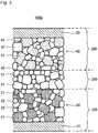
- An anode 100 includes an anode mixture layer 20 and an anode current collector layer 10 that is in contact with the anode mixture layer 20 as shown in Fig. 1 .
- the anode mixture layer 20 contains an anode active material 21 and a sulfide solid electrolyte 22 as shown in Fig. 1 .
- At least a surface of the anode current collector layer 10 which is in contact with the anode mixture layer 20 is made from material 11 that contains an alloy of copper and metal of a higher ionization tendency than copper as shown in Figs. 1 to 2C .
- At least the surface of the anode current collector layer 10, which is in contact with the anode mixture layer 20, is made from the material 11 that contains an alloy of copper and metal of a higher ionization tendency than copper. Whereby, reaction of the anode current collector layer 10 with the sulfide solid electrolyte 22 in the anode mixture layer 20 is suppressed. It can be easily determined whether or not the surface of the anode current collector layer 10 is made from the material 11 by elementary analysis or the like of the surface of the anode current collector layer 10.
- a metal of a higher ionization tendency than copper include bismuth (Bi), antimony (Sb), lead (Pb), tin (Sn), nickel (Ni), cobalt (Co), cadmium (Cd), iron (Fe), chromium (Cr), zinc (Zn), tantalum (Ta), manganese (Mn), zirconium (Zr), titanium (Ti), aluminum (Al), beryllium (Be), thorium (Th), magnesium (Mg), sodium (Na), calcium (Ca), strontium (Sr), barium (Ba), potassium (K), rubidium (Rb), cesium (Cs) and lithium (Li).
- an alloy described above may contain copper and at least one selected from zinc, beryllium and tin, and may contain copper and zinc.
- An alloy described above may contain either only one metal of a higher ionization tendency than copper, or two or more of such metals.
- any composition of an alloy of copper and metal of a higher ionization tendency than copper may be employed, and the composition thereof may be properly determined in view of the conductivity of the anode current collector layer 10 etc.
- such an alloy preferably contains 5 atm% to 99 atm% of copper, and 1 atm% to 95 atm% of metal of a higher ionization tendency than copper (as the total concentration if two or more of such metals are contained), more preferably contains 20 atm% to 96 atm% of copper, and 4 atm% to 80 atm% of metal of a higher ionization tendency than copper, further preferably contains 50 atm% to 96 atm% of copper, and 4 atm% to 50 atm% of metal of a higher ionization tendency than copper, and especially preferably contains 65 atm% to 96 atm% of copper, and 4 atm% to 35 atm% of metal of a higher ionization tendency than copper, if the total of copper and metal of a higher ionization tendency than copper is
- the material 11 may contain other elements and constituents other than the alloy in view of contamination etc. as long as the problem can be solved.
- an incidental oxide film etc. may be partially formed over the surface of the anode current collector layer 10. That is, the material 11 may contain an incidental oxide etc.
- the material 11 may contain incidental moisture as well.
- the material 11 may partially contain metal of a lower ionization tendency than copper as long as the problem can be solved.
- the material 11 substantially consists of an alloy of copper and metal of a higher ionization tendency than copper in view of exerting a more significant effect.
- the anode current collector layer 10 may take any form (shape). Only the surface of the anode current collector layer 10 may be made from the material 11, and the surface and all the inside thereof may be made from the material 11.
- the anode current collector layer 10 may be an anode current collector layer 10a that consists of the material 11 in the form of foil or a sheet as shown in Fig. 2A , and may be an anode current collector layer 10b that consists of the material 11 in the form of mesh or a punched metal as shown in Fig. 2B .
- the anode current collector layers 10a and 10b can be easily produced by, for example, shaping the material 11.
- the anode current collector layer 10 may be an anode current collector layer 10c that is made by covering the surfaces of a base material 12 made from a different material than the material 11 with the material 11 as shown in Fig. 2C . That is, the surface and the inside of the anode current collector layer 10 may be made from different materials.
- the anode current collector layer 10c can be easily produced by, for example, thinly covering the surfaces of the base material 12 with the material 11 by plating, spattering, or the like.
- the base material 12 has only to secure a mechanical strength and durability as the anode current collector layer 10c.
- the base material 12 may be made from either a metal different from the material 11, or a material other than metal (such as resin).
- the thickness of the anode current collector layer 10 is not specifically limited, can be the same as that of an anode current collector layer in a conventional anode, and for example, is preferably 0.1 ⁇ m to 1 mm and is more preferably 1 ⁇ m to 100 ⁇ m. According to findings of the inventors of the present disclosure, at least the surface of the anode current collector layer 10, which is in contact with the anode mixture layer 20, is made from the material 11, which makes it possible to suppress reaction of the anode current collector layer 10 with the sulfide solid electrolyte 22 in the anode mixture layer 20 independently of the thickness of the anode current collector layer 10. At least a part of the surface of the anode current collector layer 10 which is in contact with the sulfide solid electrolyte 22 may be made from the material 11.
- the anode mixture layer 20 is roll-pressed at high pressure together with the anode current collector layer 10 in view of improving the filling factor of the anode mixture layer 20 when the anode 100 is produced.
- fractures of the anode current collector layer 10 in roll press are preferably suppressed in view of productivity etc.
- it is effective for suppressing fractures of an anode current collector layer in roll press to thicken the anode current collector layer.
- a thickened anode current collector layer 10 in the anode 100 lowers the volumetric energy density of a battery. Therefore, fractures of the anode current collector layer 10 in roll press are preferably suppressed as the anode current collector layer 10 is thickened as little as possible.
- the anode current collector layer 10 having a predetermined mechanical strength makes it possible to suppress its fractures in roll press on the anode 100.
- the tensile strength of the anode current collector layer 10 is preferably no less than 500 MPa.
- the anode current collector layer 10 is more preferably made by containing metal foil having tensile strength of no less than 500 MPa.
- the lower limit of the tensile strength is more preferably no less than 600 MPa, and further preferably no less than 800 MPa.
- the upper limit thereof is not specifically restricted.
- the anode current collector layer 10 having such tensile strength can be easily made by, for example, adjusting the composition of an alloy in the anode current collector layer 10, or work-hardening the anode current collector layer 10. If a work-hardened anode current collector layer is further heat-treated, for example, is annealed, the tensile strength of the anode current collector layer tends to lower.
- Tensile strength of the anode current collector layer refers to tensile strength measured conforming to JIS Z 2241: 2011, using the anode current collector layer (for example, metal foil) itself as a test piece.
- fractures of the anode current collector layer 10 in roll press on the anode 100 can be suppressed when the elongation after fractures of the anode current collector layer 10 is no less than a predetermined percentage.
- the elongation after fractures of the anode current collector layer 10 is preferably no less than 7.95%.
- the anode current collector layer 10 is more preferably made by containing metal foil having an elongation after fractures of no less than 7.95%.
- the lower limit of the elongation after fractures is more preferably no less than 14%.
- the anode current collector layer 10 having such an elongation after fractures can be easily made by, for example, adjusting the composition of an alloy in the anode current collector layer 10.
- Elongation after fractures of the anode current collector layer in the present application refers to an elongation after fractures measured conforming to JIS Z 2241: 2011, using the anode current collector layer (for example, metal foil) itself as a test piece.
- the anode mixture layer 20 includes the anode active material 21 and the sulfide solid electrolyte 22 as shown in Fig. 1 .
- the anode mixture layer 20 contains the sulfide solid electrolyte 22, which results in contact between a part of the surface of the anode current collector layer 10, which is in contact with the anode mixture layer 20, and the sulfide solid electrolyte 22.
- the anode mixture layer 20 may optionally contain a conductive additive, binder, and other additives (such as thickener).
- any known one as an anode active material of a sulfide solid-state battery can be employed for the anode active material 21 contained in the anode mixture layer 20.
- active materials a material displaying a baser charge/discharge potential than a cathode active material 41 described later may be used as an anode active material.
- silicon-based active materials such as Si, Si alloys and silicon oxide
- carbon-based active materials such as graphite and hard carbon
- various oxide-based active materials such as lithium titanate
- lithium metals and lithium alloys One may be used individually, or two or more may be mixed to be used as the anode active material 21.
- the shape of the anode active material 21 is not specifically restricted, and for example, is preferably a particulate or thin filmlike shape.
- the content of the anode active material 21 in the anode mixture layer 20 is not specifically restricted, and may be equivalent to that in a conventional anode mixture layer.
- reaction of the anode current collector layer 10 with the sulfide solid electrolyte 22 in the anode mixture layer 20 is suppressed in the anode 100 of the present disclosure even when the anode mixture layer 20 containing a silicon-based active material and the sulfide solid electrolyte is layered to compose the anode 100 since the surface of the anode current collector layer 10, which is in contact with the anode mixture layer 20, is made from the material 11. That is, a fine effect can be exerted in the anode 100 of the present disclosure even if the anode active material 21 contains a silicon-based active material.
- any known one as a sulfide employed for a solid electrolyte of a sulfide solid-state battery can be employed for the sulfide solid electrolyte 22 contained in the anode mixture layer 20.
- examples thereof include solid electrolytes containing Li, P and S as constituent elements.
- Li 2 S-P 2 S 5 Li 2 S-SiS 2 , LiI-Li 2 S-SiS 2 , LiI-Si 2 S-P 2 S 5 , LiI-LiBr-Li 2 S-P 2 S 5 , LiI-Li 2 S-P 2 S 5 , LiI-Li 2 O-Li 2 S-P 2 S 5 , LiI-Li 2 S-P 2 O 5 , Lil-Li 3 PO 4 -P 2 S 5 and Li 2 S-P 2 S 5 -GeS 2 .
- a sulfide solid electrolyte containing Li 2 S-P 2 S 5 among them is more preferable.
- One may be used alone, or two or more may be mixed to be used as the sulfide solid electrolyte 22.
- the shape of the sulfide solid electrolyte 22 is not specifically limited, and for example, may be a particulate shape.
- the content of the sulfide solid electrolyte 22 in the anode mixture layer 20 is not specifically limited, and may be equivalent to that in a conventional anode mixture layer.
- the anode mixture layer 20 may contain an inorganic solid electrolyte other than the sulfide solid electrolyte 22 in addition to the sulfide solid electrolyte 22 as long as a desired effect can be brought about.
- examples thereof include oxide solid electrolytes.
- any one known as a conductive additive employed for a sulfide solid-state battery can be employed for a conductive additive contained in the anode mixture layer 20 as an optional constituent.
- a conductive additive employed for a sulfide solid-state battery
- examples thereof include carbon materials such as acetylene black (AB), Ketjen black (KB), vapor grown carbon fiber (VGCF), carbon nanotubes (CNT), carbon nanofiber (CNF), and graphite; and metallic materials such as nickel, aluminum, and stainless steel.
- metallic materials such as nickel, aluminum, and stainless steel.
- One conductive additive may be used individually, or two or more conductive additives may be mixed to be used.
- the shape of the conductive additive is not specifically limited, and for example, is preferable a particulate or fibrous shape.
- the content of the conductive additive in the anode mixture layer 20 is not specifically limited, and may be equivalent to that in a conventional anode mixture layer.
- binder employed in a sulfide solid-state battery can be employed for binder contained in the anode mixture layer 20 as an optional constituent.
- binder examples thereof include styrene-butadiene rubber (SBR), carboxymethyl cellulose (CMC), acrylonitrile-butadiene rubber (ABR), butadiene rubber (BR), polyvinylidene fluoride (PVdF), polytetrafluoroethylene (PTFE), and polyimides (PI).
- SBR styrene-butadiene rubber
- CMC carboxymethyl cellulose
- ABR acrylonitrile-butadiene rubber
- BR butadiene rubber
- PVdF polyvinylidene fluoride
- PTFE polytetrafluoroethylene
- PI polyimides
- One binder may be used individually, or two or more binders may be mixed to be used.
- the content of the binder in the anode mixture layer 20 is not specifically limited, and may
- the anode 100 having the structure described above can be easily produced by passing through processes such as putting and kneading the anode active material 21, the sulfide solid electrolyte 22, and a conductive additive, binder, etc. which are optionally contained, in nonaqueous solvent to obtain a slurry electrode composition, and thereafter applying this electrode composition to the surface of the anode current collector layer 10, drying the surface, and optionally pressing the anode current collector layer 10.
- the anode 100 can be produced by not only such a wet process, but also, for example, press molding in a dry process.
- the thickness of the anode mixture layer 20 is, for example, preferably 0.1 ⁇ m to 1 mm, and more preferably 1 ⁇ m to 100 ⁇ m when the anode mixture layer 20 in the form of a sheet is formed over the surface of the anode current collector layer 10 as described above.
- Fig. 3 schematically shows structure of a sulfide solid-state battery 1000.
- the sulfide solid-state battery 1000 includes the anode 100 of the present disclosure, a cathode 200, and a solid electrolyte layer 300 provided between the anode 100 and the cathode 200.
- the solid electrolyte layer 300 is in contact with the anode mixture layer 20 of the anode 100, and a cathode mixture layer 40 of the cathode 200. Terminals, a battery case, etc. are omitted to be shown in Fig. 3 .
- the structure of the cathode 200 and the solid electrolyte layer 300 in the sulfide solid-state battery 1000 is obvious, and hereinafter one example will be described.
- the cathode 200 includes the cathode mixture layer 40, and the cathode current collector layer 30 that is in contact with the cathode mixture layer 40 as shown in Fig. 3 .
- the cathode current collector layer 30 may be composed of metal foil, a metal mesh, etc., and is especially preferably composed of metal foil. Examples of a metal constituting the cathode current collector layer 30 include stainless steel, nickel, chromium, gold, platinum, aluminum, iron, titanium and zinc.
- the cathode current collector layer 30 may be metal foil or a base material, a surface of which is plated with metal as described above, or on the surface of which metal as described above is deposited.
- the thickness of the cathode current collector layer 30 is not specifically limited, and for example, is preferably 0.1 ⁇ m to 1 mm, and is more preferably 1 ⁇ m to 100 ⁇ m.
- the cathode mixture layer 40 contains the cathode active material 41 as shown in Fig. 3 .
- the cathode mixture layer 40 may optionally contain a solid electrolyte 42, a conductive additive, binder, and other additives (such as thickener).
- cathode active material 41 contained in the cathode mixture layer 40.
- a material displaying a nobler charge/discharge potential than the anode active material 21 described above may be used as a cathode active material.
- the cathode active material 41 examples include lithium-containing oxides such as lithium cobaltate, lithium nickelate, Li(Ni,Mn,Co)O 2 (Li 1 + ⁇ Ni 1/3 Mn 1/3 Co 1/3 O 2 ), lithium manganate, spinel lithium composite oxides, lithium titanate, and lithium metal phosphates (LiMPO 4 where M is at least one selected from Fe, Mn, Co and Ni).
- lithium-containing oxides such as lithium cobaltate, lithium nickelate, Li(Ni,Mn,Co)O 2 (Li 1 + ⁇ Ni 1/3 Mn 1/3 Co 1/3 O 2 ), lithium manganate, spinel lithium composite oxides, lithium titanate, and lithium metal phosphates (LiMPO 4 where M is at least one selected from Fe, Mn, Co and Ni).
- the cathode active material 41 may have a coating layer of lithium niobate, lithium titanate, lithium phosphate, or the like, over its surface.
- the shape of the cathode active material 41 is not specifically restricted, and for example, is preferably a particulate or thin filmlike shape.
- the content of the cathode active material 41 in the cathode mixture layer 40 is not specifically restricted, and may be equivalent to that in a conventional cathode mixture layer.
- any known one as a sulfide solid electrolyte of a sulfide solid-state battery can be employed as the solid electrolyte 42 contained in the cathode mixture layer 40 as an optional constituent.
- a sulfide solid electrolyte as described above is preferably employed.
- An inorganic solid electrolyte other than a sulfide solid electrolyte may be contained in addition to a sulfide solid electrolyte as long as a desired effect can be brought about.
- the shape of the solid electrolyte 42 is not specifically limited, and for example, is preferably a particulate shape.
- the content of the solid electrolyte 42 in the cathode mixture layer 40 is not specifically limited, and may be equivalent to that in a conventional cathode mixture layer.
- any one known as a conductive additive employed for a sulfide solid-state battery can be employed as a conductive additive contained in the cathode mixture layer 40 as an optional constituent.
- a conductive additive employed for a sulfide solid-state battery
- examples thereof include carbon materials such as acetylene black (AB), Ketjen black (KB), vapor grown carbon fiber (VGCF), carbon nanotubes (CNT), carbon nanofiber (CNF), and graphite; and metallic materials such as nickel, aluminum, and stainless steel. Especially carbon materials are preferable.
- One conductive additive may be used individually, or two or more conductive additives may be mixed to be used.
- the shape of the conductive additive is not specifically limited, and for example, is preferably a particulate shape.
- the content of the conductive additive in the cathode mixture layer 40 is not specifically limited, and may be equivalent to that in a conventional cathode mixture layer.
- binder employed in a sulfide solid-state battery can be employed for binder contained in the cathode mixture layer 40 as an optional constituent.
- binder examples thereof include styrene-butadiene rubber (SBR), carboxymethyl cellulose (CMC), acrylonitrile-butadiene rubber (ABR), butadiene rubber (BR), polyvinylidene fluoride (PVdF), and polytetrafluoroethylene (PTFE).
- SBR styrene-butadiene rubber
- CMC carboxymethyl cellulose
- ABR acrylonitrile-butadiene rubber
- BR butadiene rubber
- PVdF polyvinylidene fluoride
- PTFE polytetrafluoroethylene
- One binder may be used individually, or two or more binders may be mixed to be used.
- the content of the binder in the cathode mixture layer 40 is not specifically limited, and may be equivalent to that in a conventional catho
- the cathode 200 having the structure described above can be easily produced by passing through processes such as putting and kneading the cathode active material 41, and the solid electrolyte 42, binder, a conductive additive, etc. which are optionally contained, in nonaqueous solvent to obtain a slurry electrode composition, and thereafter applying this electrode composition to a surface of the cathode current collector layer 30, drying the surface, and optionally pressing the cathode current collector layer 30.
- the cathode 200 can be produced by not only such a wet process, but also, for example, press molding in a dry process.
- the thickness of the cathode mixture layer 40 is, for example, preferably 0.1 ⁇ m to 1 mm, and more preferably 1 ⁇ m to 100 ⁇ m when the cathode mixture layer 40 in the form of a sheet is formed over a surface of the cathode current collector layer 30 as described above.
- the solid electrolyte layer 300 has functions of insulating the anode 100 from the cathode 200, and conducting a lithium ion between the anode 100 and the cathode 200.
- the solid electrolyte layer 300 contains at least a solid electrolyte 51.
- the solid electrolyte layer 300 preferably contains binder.
- the solid electrolyte 51 contained in the solid electrolyte layer 300 may be properly selected from the examples of solid electrolytes that may be contained in the anode mixture layer 20 and the cathode mixture layer 40. Specifically, a sulfide solid electrolyte is preferable, and a sulfide solid electrolyte containing Li 2 S-P 2 S 5 is more preferable. One may be used individually, or two or more may be mixed to be used as the solid electrolyte 51.
- the shape of the solid electrolyte 51 may be a popular shape, that is, a particulate shape.
- the content of the solid electrolyte 51 in the solid electrolyte layer 300 is not specifically restricted, and may be properly determined according to the performance of the battery to be aimed. For example, the content of the solid electrolyte is preferably no less than 90 mass%, and more preferably no less than 95 mass% if the whole of the solid electrolyte layer 300 is 100 mass%.
- the solid electrolyte layer 300 is preferably contains binder.
- Binder that may be contained in the solid electrolyte layer 300 is publicly known.
- binder may be properly selected from the examples of binder that may be contained in the anode mixture layer 20 and the cathode mixture layer 40.
- the solid electrolyte layer 300 having the structure described above can be easily produced by passing through processes such as putting and kneading the solid electrolyte 51, and optionally contained binder etc., in nonaqueous solvent to obtain a slurry electrolyte composition, and thereafter applying this electrolyte composition to surfaces of a base material (or the surface of the anode mixture layer 20 or the surface of the cathode mixture layer 40), drying the surfaces, and optionally pressing the base material.
- the solid electrolyte layer 300 can be produced by not only such a wet process, but also, for example, press forming in a dry process.
- the thickness of the solid electrolyte layer 300 is, for example, preferably 0.1 ⁇ m to 1 mm, and more preferably 1 ⁇ m to 100 ⁇ m when the solid electrolyte layer 300 in the form of a sheet is formed as described above.
- All the components of the sulfide solid-state battery 1000 are not necessarily solids.
- the sulfide solid-state battery 1000 may partially contain liquids such as electrolyte solution as long as the battery performance is not spoiled.
- the sulfide solid-state battery 1000 having the above described structure can be produced as follows: that is, a method for producing the sulfide solid-state battery 1000 includes a step of producing the anode 100, the cathode 200 and the solid electrolyte layer 300 according to the above described ways, and a step of layering the anode 100, the cathode 200 and the solid electrolyte layer 300.
- the sulfide solid-state battery 1000 can be produced by, for example, layering the anode 100, the solid electrolyte layer 300 and the cathode 200 as described above to form a laminate, attaching proper terminals etc. thereto, and then sealing up the laminate in the battery case.
- a layer made from a sulfide solid electrolyte (its main constituent is Li 2 S-P 2 S 5 ) (thickness: 450 ⁇ m) was sandwiched between predetermined metal foil and In-Li foil (thickness: 80 ⁇ m), and the metal foil and the In-Li foil were connected to a power source, to evaluate the reactivity of the metal foil to the sulfide solid electrolyte by cyclic voltammetry (CV).
- the types of the metal foil used in Examples and Comparative Examples were as follows.
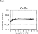
- Figs. 5 to 9 show CV results of Examples and Comparative Examples.
- Fig. 5 corresponds to Comparative Example 1
- Fig. 6 corresponds to Example 1
- Fig. 7 corresponds to Example 2
- Fig. 8 corresponds to Example 3
- Fig. 9 corresponds to Comparative Example 2.
- Values represented by the vertical axis in Fig. 5 are 100 times as large as those in Figs. 6 to 8 . It can be said that the electrochemical reactivity to the sulfide solid electrolyte was high as the current density (vertical axis) widely fluctuates in Figs. 5 to 9 .
- Beryllium, zinc and tin were given as examples of metal of a higher ionization tendency than copper in Examples 1 to 3.
- the technique of the present disclosure is believed to exert the same effect as well when a metal other than them are used as metal of a higher ionization tendency than copper.
- zinc and tin include bismuth (Bi), antimony (Sb), lead (Pb), nickel (Ni), cobalt (Co), cadmium (Cd), iron (Fe), chromium (Cr), tantalum (Ta), manganese (Mn), zirconium (Zr), titanium (Ti), aluminum (Al), thorium (Th), magnesium (Mg), sodium (Na), calcium (Ca), strontium (Sr), barium (Ba), potassium (K), rubidium (Rb), cesium (Cs) and lithium (Li).
- Copper-based alloys having predetermined compositions were given in Examples 1 to 3.
- the composition of a copper-based alloy is not specifically restricted in the technique of the present disclosure. This composition may be properly determined according to the performance of the battery to be aimed in view of the reactivity to the sulfide solid electrolyte, conductivity as an anode current collector layer, etc.
- a solution of butyl butyrate and 5 wt% of a PVdF based binder (manufactured by Kureha Corporation), silicone (manufactured by Kojundo Chemical Laboratory Co., Ltd., 5 ⁇ m in mean particle diameter (D 50 )) as an anode active material, and a sulfide solid electrolyte were added into a vessel made from PP, and stirred with an ultrasonic dispersive device (UH-50 manufactured by SMT Corporation) for 30 seconds. Next, the vessel was shaken with a mixer (TTM-1 manufactured by Sibata Scientific Technology Ltd.) for 30 minutes, and the inside thereof was further stirred with the ultrasonic dispersive device for 30 seconds.
- a mixer TTM-1 manufactured by Sibata Scientific Technology Ltd.
- the vessel was further shaken with the mixer for 3 minutes, to obtain an anode mixture slurry.
- Sheets of metal foil having various levels of tensile strength were coated with the obtained anode mixture slurry using an applicator according to a blade method. After air-dried, the metal foil was dried on a hot plate at 100°C for 30 minutes, to form an anode mixture layer on the metal foil.
- a solid electrolyte layer and a cathode mixture layer which were formed by coating were layered onto the anode mixture layer by transferring, thereafter to be roll-pressed at the maximum linear pressure (linear pressure: 5 t/cm) at 0.5 m/min in feed speed for the purpose of improving the filling factor of an electrode body that was made by transferring (anode mixture layer + solid electrolyte layer + cathode mixture layer) to bring out properties of a battery.
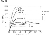
- Tensile strength of metal foil of even the same composition and same thickness may vary according to whether or not to be work-hardened and whether or not to be heat-treated (annealed) as shown in Fig. 10 . It was found that the copper alloy foil according to Examples 1 to 3 was material having such potential that tensile strength thereof greatly exceeded 500 MPa as shown in Fig. 10 , and was able to sufficiently bear roll press when an anode was produced. That is, it can be said that an alloy constituting an anode current collector layer preferably contains copper, and at least one selected from zinc, beryllium and tin.
- An anode mixture layer was formed over a surface of metal foil through the same procedures as those in the evaluation of the tensile strength, and thereafter was roll-pressed at such a maximum linear pressure (5 t/cm) and feed speed of 0.5 m/min that the filling factor of the anode mixture layer was improved while properties of material of the anode mixture layer was kept.
- an anode current collector layer preferably satisfies at least one of the following requirements (1) and (2) in order to suppress fractures of the anode current collector layer in roll press when an anode is produced:
- a sulfide solid-state battery including the anode of the present disclosure can be preferably used as a power source in a wide range such as a small-sized power source for portable devices and an onboard large-sized power source.
Landscapes
- Chemical & Material Sciences (AREA)
- Electrochemistry (AREA)
- General Chemical & Material Sciences (AREA)
- Chemical Kinetics & Catalysis (AREA)
- Engineering & Computer Science (AREA)
- Materials Engineering (AREA)
- Manufacturing & Machinery (AREA)
- Inorganic Chemistry (AREA)
- Physics & Mathematics (AREA)
- Condensed Matter Physics & Semiconductors (AREA)
- General Physics & Mathematics (AREA)
- Composite Materials (AREA)
- Cell Electrode Carriers And Collectors (AREA)
- Battery Electrode And Active Subsutance (AREA)
- Secondary Cells (AREA)
Abstract
Description
- The present application discloses an anode and a sulfide solid-state battery using a sulfide solid electrolyte.
- When an anode is composed using an anode current collector layer made from copper, and an anode mixture layer containing a sulfide solid electrolyte in a sulfide solid-state battery including the anode, a cathode, and a solid electrolyte layer, copper reacts with the sulfide solid electrolyte to generate copper sulfide etc., which increases the resistance of the interface between the anode current collector layer and the anode mixture layer and leads to an irreversible reaction of copper sulfide with a lithium ion, to lower the battery capacity, which is problematic.
Patent Literature 1 discloses, as one means for solving this problem, to provide a reaction-inhibiting layer containing a predetermined element between an anode mixture layer and an anode current collector layer. - Such a technique is known as disclosed in
Patent Literature 2 as to suppress reaction of an active material with a sulfide solid electrolyte in a sulfide solid-state battery. However, it is difficult to use this technique as a technique for suppressing reaction of an anode current collector layer with a sulfide solid electrolyte. -
- Patent Literature 1:
JP 2012-049023 A - Patent Literature 2:
JP 2011-060649 A - A reaction-inhibiting layer has to be added between an anode mixture layer and an anode current collector layer in the technique disclosed in
Patent Literature 1, which raises problems of complicated steps of producing a battery, and a low volumetric energy density of the battery. That is, an object is how to suppress reaction of an anode current collector layer with a sulfide solid electrolyte in an anode mixture layer without especially adding a reaction-inhibiting layer. - The present application discloses, as one means for solving the problem, an anode comprising: an anode mixture layer; and an anode current collector layer that is in contact with the anode mixture layer, wherein the anode mixture layer contains an anode active material and a sulfide solid electrolyte, and at least a surface of the anode current collector layer is made from material that contains an alloy of copper and metal of a higher ionization tendency than copper, the surface being in contact with the anode mixture layer.
- In the anode of the present disclosure, the alloy preferably contains copper, and at least one selected from zinc, beryllium, and tin.
- In the anode of the present disclosure, the alloy preferably contains copper and zinc.
- In the anode of the present disclosure, the anode active material preferably contains a silicon-based active material.
- In the anode of the present disclosure, tensile strength of the anode current collector layer is preferably no less than 500 MPa.
- In the anode of the present disclosure, an elongation after fractures of the anode current collector layer is preferably no less than 7.95%.
- The present application discloses, as one means for solving the problem, a sulfide solid-state battery comprising: the anode of the present application; a cathode; and a solid electrolyte layer provided between the anode and the cathode.
- According to new findings of the inventors of the present disclosure, when copper is combined with metal of a higher ionization tendency than copper to alloy, its electrochemical reactivity to a sulfide solid electrolyte is low compared to the case of copper only. Even when such an alloy electrochemically reacts with a sulfide solid electrolyte, metal of a higher ionization tendency than copper is believed to react with a sulfide solid electrolyte priorly, which makes it possible to suppress generation of copper sulfide, which is disadvantageous in a charge/discharge reaction. That is, a surface of an anode current collector layer is made from material containing a predetermined alloy like the anode of the present disclosure, which makes it possible to suppress reaction of the anode current collector layer with a sulfide solid electrolyte in an anode mixture layer without newly adding a reaction-inhibiting layer.
-
-
Fig. 1 is an explanatory schematic view of one example of ananode 100; -
Figs. 2A to 2C are explanatory schematic views of examples of an anodecurrent collector 10; -
Fig. 3 is an explanatory schematic view of structure of a sulfide solid-state battery 1000; -
Fig. 4 is an explanatory schematic view of structure of an evaluation device used in Examples; -
Fig. 5 shows a CV evaluation result of Comparative Example 1; -
Fig. 6 shows a CV evaluation result of Example 1; -
Fig. 7 shows a CV evaluation result of Example 2; -
Fig. 8 shows a CV evaluation result of Example 3; -
Fig. 9 shows a CV evaluation result of Comparative Example 2; -
Fig. 10 is a graph of comparing various types of copper alloy foil (Examples 1A to 3A and 1B to 3B) and copper foil (Comparative Examples 1A and 1B) in tensile strength; and -
Fig. 11 is a graph of comparing various types of copper alloy foil (Examples 1B and 3B) and copper foil (Comparative Examples 1A and 1B) in elongation after fractures. - An
anode 100 includes ananode mixture layer 20 and an anodecurrent collector layer 10 that is in contact with theanode mixture layer 20 as shown inFig. 1 . Theanode mixture layer 20 contains an anodeactive material 21 and a sulfidesolid electrolyte 22 as shown inFig. 1 . At least a surface of the anodecurrent collector layer 10 which is in contact with theanode mixture layer 20 is made frommaterial 11 that contains an alloy of copper and metal of a higher ionization tendency than copper as shown inFigs. 1 to 2C . - At least the surface of the anode
current collector layer 10, which is in contact with theanode mixture layer 20, is made from thematerial 11 that contains an alloy of copper and metal of a higher ionization tendency than copper. Whereby, reaction of the anodecurrent collector layer 10 with the sulfidesolid electrolyte 22 in theanode mixture layer 20 is suppressed. It can be easily determined whether or not the surface of the anodecurrent collector layer 10 is made from thematerial 11 by elementary analysis or the like of the surface of the anodecurrent collector layer 10. Specific example of a metal of a higher ionization tendency than copper include bismuth (Bi), antimony (Sb), lead (Pb), tin (Sn), nickel (Ni), cobalt (Co), cadmium (Cd), iron (Fe), chromium (Cr), zinc (Zn), tantalum (Ta), manganese (Mn), zirconium (Zr), titanium (Ti), aluminum (Al), beryllium (Be), thorium (Th), magnesium (Mg), sodium (Na), calcium (Ca), strontium (Sr), barium (Ba), potassium (K), rubidium (Rb), cesium (Cs) and lithium (Li). Among them, zinc (Zn), beryllium (Be) and tin (Sn) are preferable, and zinc (Zn) is especially preferable. That is, an alloy described above may contain copper and at least one selected from zinc, beryllium and tin, and may contain copper and zinc. An alloy described above may contain either only one metal of a higher ionization tendency than copper, or two or more of such metals. - Any composition of an alloy of copper and metal of a higher ionization tendency than copper may be employed, and the composition thereof may be properly determined in view of the conductivity of the anode
current collector layer 10 etc. For example, such an alloy preferably contains 5 atm% to 99 atm% of copper, and 1 atm% to 95 atm% of metal of a higher ionization tendency than copper (as the total concentration if two or more of such metals are contained), more preferably contains 20 atm% to 96 atm% of copper, and 4 atm% to 80 atm% of metal of a higher ionization tendency than copper, further preferably contains 50 atm% to 96 atm% of copper, and 4 atm% to 50 atm% of metal of a higher ionization tendency than copper, and especially preferably contains 65 atm% to 96 atm% of copper, and 4 atm% to 35 atm% of metal of a higher ionization tendency than copper, if the total of copper and metal of a higher ionization tendency than copper is 100 atm%. Such an alloy may contain incidental impurities. The concentration of incidental impurities therein is preferably no more than 1 atm% if the whole of the alloy is 100 atm%. - The
material 11 may contain other elements and constituents other than the alloy in view of contamination etc. as long as the problem can be solved. For example, an incidental oxide film etc. may be partially formed over the surface of the anodecurrent collector layer 10. That is, thematerial 11 may contain an incidental oxide etc. Thematerial 11 may contain incidental moisture as well. Thematerial 11 may partially contain metal of a lower ionization tendency than copper as long as the problem can be solved. Preferably, thematerial 11 substantially consists of an alloy of copper and metal of a higher ionization tendency than copper in view of exerting a more significant effect. - At least the surface of the anode
current collector layer 10, which is in contact with theanode mixture layer 20, has only to be made from thematerial 11, and the anodecurrent collector layer 10 may take any form (shape). Only the surface of the anodecurrent collector layer 10 may be made from thematerial 11, and the surface and all the inside thereof may be made from thematerial 11. For example, the anodecurrent collector layer 10 may be an anodecurrent collector layer 10a that consists of thematerial 11 in the form of foil or a sheet as shown inFig. 2A , and may be an anodecurrent collector layer 10b that consists of the material 11 in the form of mesh or a punched metal as shown inFig. 2B . The anode current collector layers 10a and 10b can be easily produced by, for example, shaping thematerial 11. Alternatively, the anodecurrent collector layer 10 may be an anodecurrent collector layer 10c that is made by covering the surfaces of abase material 12 made from a different material than the material 11 with the material 11 as shown inFig. 2C . That is, the surface and the inside of the anodecurrent collector layer 10 may be made from different materials. The anodecurrent collector layer 10c can be easily produced by, for example, thinly covering the surfaces of thebase material 12 with thematerial 11 by plating, spattering, or the like. Thebase material 12 has only to secure a mechanical strength and durability as the anodecurrent collector layer 10c. For example, thebase material 12 may be made from either a metal different from thematerial 11, or a material other than metal (such as resin). - The thickness of the anode
current collector layer 10 is not specifically limited, can be the same as that of an anode current collector layer in a conventional anode, and for example, is preferably 0.1 µm to 1 mm and is more preferably 1 µm to 100 µm. According to findings of the inventors of the present disclosure, at least the surface of the anodecurrent collector layer 10, which is in contact with theanode mixture layer 20, is made from thematerial 11, which makes it possible to suppress reaction of the anodecurrent collector layer 10 with the sulfidesolid electrolyte 22 in theanode mixture layer 20 independently of the thickness of the anodecurrent collector layer 10. At least a part of the surface of the anodecurrent collector layer 10 which is in contact with the sulfidesolid electrolyte 22 may be made from thematerial 11. - There is a case where the
anode mixture layer 20 is roll-pressed at high pressure together with the anodecurrent collector layer 10 in view of improving the filling factor of theanode mixture layer 20 when theanode 100 is produced. Here, fractures of the anodecurrent collector layer 10 in roll press are preferably suppressed in view of productivity etc. For example, it is effective for suppressing fractures of an anode current collector layer in roll press to thicken the anode current collector layer. However, a thickened anodecurrent collector layer 10 in theanode 100 lowers the volumetric energy density of a battery. Therefore, fractures of the anodecurrent collector layer 10 in roll press are preferably suppressed as the anodecurrent collector layer 10 is thickened as little as possible. - According to new findings of the inventors of the present disclosure, the anode
current collector layer 10 having a predetermined mechanical strength makes it possible to suppress its fractures in roll press on theanode 100. Specifically, the tensile strength of the anodecurrent collector layer 10 is preferably no less than 500 MPa. Alternatively, the anodecurrent collector layer 10 is more preferably made by containing metal foil having tensile strength of no less than 500 MPa. The lower limit of the tensile strength is more preferably no less than 600 MPa, and further preferably no less than 800 MPa. The upper limit thereof is not specifically restricted. The anodecurrent collector layer 10 having such tensile strength can be easily made by, for example, adjusting the composition of an alloy in the anodecurrent collector layer 10, or work-hardening the anodecurrent collector layer 10. If a work-hardened anode current collector layer is further heat-treated, for example, is annealed, the tensile strength of the anode current collector layer tends to lower. - "Tensile strength of the anode current collector layer" in the present application refers to tensile strength measured conforming to JIS Z 2241: 2011, using the anode current collector layer (for example, metal foil) itself as a test piece.
- According to new findings of the inventors of the present disclosure, fractures of the anode
current collector layer 10 in roll press on theanode 100 can be suppressed when the elongation after fractures of the anodecurrent collector layer 10 is no less than a predetermined percentage. Specifically, the elongation after fractures of the anodecurrent collector layer 10 is preferably no less than 7.95%. Alternatively, the anodecurrent collector layer 10 is more preferably made by containing metal foil having an elongation after fractures of no less than 7.95%. The lower limit of the elongation after fractures is more preferably no less than 14%. The anodecurrent collector layer 10 having such an elongation after fractures can be easily made by, for example, adjusting the composition of an alloy in the anodecurrent collector layer 10. - "Elongation after fractures of the anode current collector layer" in the present application refers to an elongation after fractures measured conforming to JIS Z 2241: 2011, using the anode current collector layer (for example, metal foil) itself as a test piece.
- The
anode mixture layer 20 includes the anodeactive material 21 and the sulfidesolid electrolyte 22 as shown inFig. 1 . Theanode mixture layer 20 contains the sulfidesolid electrolyte 22, which results in contact between a part of the surface of the anodecurrent collector layer 10, which is in contact with theanode mixture layer 20, and the sulfidesolid electrolyte 22. Theanode mixture layer 20 may optionally contain a conductive additive, binder, and other additives (such as thickener). - Any known one as an anode active material of a sulfide solid-state battery can be employed for the anode
active material 21 contained in theanode mixture layer 20. Among known active materials, a material displaying a baser charge/discharge potential than a cathodeactive material 41 described later may be used as an anode active material. Examples thereof include silicon-based active materials such as Si, Si alloys and silicon oxide; carbon-based active materials such as graphite and hard carbon; various oxide-based active materials such as lithium titanate; and lithium metals and lithium alloys. One may be used individually, or two or more may be mixed to be used as the anodeactive material 21. The shape of the anodeactive material 21 is not specifically restricted, and for example, is preferably a particulate or thin filmlike shape. The content of the anodeactive material 21 in theanode mixture layer 20 is not specifically restricted, and may be equivalent to that in a conventional anode mixture layer. - There is a risk of reaction of copper with a sulfide solid electrolyte at OCV of a silicon-based active material in a conventional anode when an anode mixture layer containing the silicon-based active material and the sulfide solid electrolyte is layered onto a surface of an anode current collector layer made from copper to compose the anode. That is, there is a risk of reaction of the anode current collector layer with the sulfide solid electrolyte in the anode mixture layer just after the anode mixture layer is formed over the surface of the anode current collector layer. In contrast, reaction of the anode
current collector layer 10 with the sulfidesolid electrolyte 22 in theanode mixture layer 20 is suppressed in theanode 100 of the present disclosure even when theanode mixture layer 20 containing a silicon-based active material and the sulfide solid electrolyte is layered to compose theanode 100 since the surface of the anodecurrent collector layer 10, which is in contact with theanode mixture layer 20, is made from thematerial 11. That is, a fine effect can be exerted in theanode 100 of the present disclosure even if the anodeactive material 21 contains a silicon-based active material. - Any known one as a sulfide employed for a solid electrolyte of a sulfide solid-state battery can be employed for the sulfide
solid electrolyte 22 contained in theanode mixture layer 20. Examples thereof include solid electrolytes containing Li, P and S as constituent elements. Specific examples thereof include Li2S-P2S5, Li2S-SiS2, LiI-Li2S-SiS2, LiI-Si2S-P2S5, LiI-LiBr-Li2S-P2S5, LiI-Li2S-P2S5, LiI-Li2O-Li2S-P2S5, LiI-Li2S-P2O5, Lil-Li3PO4-P2S5 and Li2S-P2S5-GeS2. Specifically, a sulfide solid electrolyte containing Li2S-P2S5 among them is more preferable. One may be used alone, or two or more may be mixed to be used as the sulfidesolid electrolyte 22. The shape of the sulfidesolid electrolyte 22 is not specifically limited, and for example, may be a particulate shape. The content of the sulfidesolid electrolyte 22 in theanode mixture layer 20 is not specifically limited, and may be equivalent to that in a conventional anode mixture layer. - The
anode mixture layer 20 may contain an inorganic solid electrolyte other than the sulfidesolid electrolyte 22 in addition to the sulfidesolid electrolyte 22 as long as a desired effect can be brought about. Examples thereof include oxide solid electrolytes. - Any one known as a conductive additive employed for a sulfide solid-state battery can be employed for a conductive additive contained in the
anode mixture layer 20 as an optional constituent. Examples thereof include carbon materials such as acetylene black (AB), Ketjen black (KB), vapor grown carbon fiber (VGCF), carbon nanotubes (CNT), carbon nanofiber (CNF), and graphite; and metallic materials such as nickel, aluminum, and stainless steel. Especially carbon materials are preferable. One conductive additive may be used individually, or two or more conductive additives may be mixed to be used. The shape of the conductive additive is not specifically limited, and for example, is preferable a particulate or fibrous shape. The content of the conductive additive in theanode mixture layer 20 is not specifically limited, and may be equivalent to that in a conventional anode mixture layer. - Any known one as binder employed in a sulfide solid-state battery can be employed for binder contained in the
anode mixture layer 20 as an optional constituent. Examples thereof include styrene-butadiene rubber (SBR), carboxymethyl cellulose (CMC), acrylonitrile-butadiene rubber (ABR), butadiene rubber (BR), polyvinylidene fluoride (PVdF), polytetrafluoroethylene (PTFE), and polyimides (PI). One binder may be used individually, or two or more binders may be mixed to be used. The content of the binder in theanode mixture layer 20 is not specifically limited, and may be equivalent to that in a conventional anode mixture layer. - The
anode 100 having the structure described above can be easily produced by passing through processes such as putting and kneading the anodeactive material 21, the sulfidesolid electrolyte 22, and a conductive additive, binder, etc. which are optionally contained, in nonaqueous solvent to obtain a slurry electrode composition, and thereafter applying this electrode composition to the surface of the anodecurrent collector layer 10, drying the surface, and optionally pressing the anodecurrent collector layer 10. Theanode 100 can be produced by not only such a wet process, but also, for example, press molding in a dry process. The thickness of theanode mixture layer 20 is, for example, preferably 0.1 µm to 1 mm, and more preferably 1 µm to 100 µm when theanode mixture layer 20 in the form of a sheet is formed over the surface of the anodecurrent collector layer 10 as described above. -
Fig. 3 schematically shows structure of a sulfide solid-state battery 1000. The sulfide solid-state battery 1000 includes theanode 100 of the present disclosure, acathode 200, and asolid electrolyte layer 300 provided between theanode 100 and thecathode 200. Thesolid electrolyte layer 300 is in contact with theanode mixture layer 20 of theanode 100, and acathode mixture layer 40 of thecathode 200. Terminals, a battery case, etc. are omitted to be shown inFig. 3 . The structure of thecathode 200 and thesolid electrolyte layer 300 in the sulfide solid-state battery 1000 is obvious, and hereinafter one example will be described. - The
cathode 200 includes thecathode mixture layer 40, and the cathodecurrent collector layer 30 that is in contact with thecathode mixture layer 40 as shown inFig. 3 . - The cathode
current collector layer 30 may be composed of metal foil, a metal mesh, etc., and is especially preferably composed of metal foil. Examples of a metal constituting the cathodecurrent collector layer 30 include stainless steel, nickel, chromium, gold, platinum, aluminum, iron, titanium and zinc. The cathodecurrent collector layer 30 may be metal foil or a base material, a surface of which is plated with metal as described above, or on the surface of which metal as described above is deposited. The thickness of the cathodecurrent collector layer 30 is not specifically limited, and for example, is preferably 0.1 µm to 1 mm, and is more preferably 1 µm to 100 µm. - The
cathode mixture layer 40 contains the cathodeactive material 41 as shown inFig. 3 . Thecathode mixture layer 40 may optionally contain asolid electrolyte 42, a conductive additive, binder, and other additives (such as thickener). - Any known one as a cathode active material of a sulfide solid-state battery can be employed for the cathode
active material 41 contained in thecathode mixture layer 40. Among known active materials, a material displaying a nobler charge/discharge potential than the anodeactive material 21 described above may be used as a cathode active material. Examples of the cathodeactive material 41 include lithium-containing oxides such as lithium cobaltate, lithium nickelate, Li(Ni,Mn,Co)O2(Li1+αNi1/3Mn1/3Co1/3O2), lithium manganate, spinel lithium composite oxides, lithium titanate, and lithium metal phosphates (LiMPO4 where M is at least one selected from Fe, Mn, Co and Ni). One may be used individually, or two or more may be mixed to be used as the cathodeactive material 41. The cathodeactive material 41 may have a coating layer of lithium niobate, lithium titanate, lithium phosphate, or the like, over its surface. The shape of the cathodeactive material 41 is not specifically restricted, and for example, is preferably a particulate or thin filmlike shape. The content of the cathodeactive material 41 in thecathode mixture layer 40 is not specifically restricted, and may be equivalent to that in a conventional cathode mixture layer. - Any known one as a sulfide solid electrolyte of a sulfide solid-state battery can be employed as the
solid electrolyte 42 contained in thecathode mixture layer 40 as an optional constituent. For example, a sulfide solid electrolyte as described above is preferably employed. An inorganic solid electrolyte other than a sulfide solid electrolyte may be contained in addition to a sulfide solid electrolyte as long as a desired effect can be brought about. The shape of thesolid electrolyte 42 is not specifically limited, and for example, is preferably a particulate shape. The content of thesolid electrolyte 42 in thecathode mixture layer 40 is not specifically limited, and may be equivalent to that in a conventional cathode mixture layer. - Any one known as a conductive additive employed for a sulfide solid-state battery can be employed as a conductive additive contained in the
cathode mixture layer 40 as an optional constituent. Examples thereof include carbon materials such as acetylene black (AB), Ketjen black (KB), vapor grown carbon fiber (VGCF), carbon nanotubes (CNT), carbon nanofiber (CNF), and graphite; and metallic materials such as nickel, aluminum, and stainless steel. Especially carbon materials are preferable. One conductive additive may be used individually, or two or more conductive additives may be mixed to be used. The shape of the conductive additive is not specifically limited, and for example, is preferably a particulate shape. The content of the conductive additive in thecathode mixture layer 40 is not specifically limited, and may be equivalent to that in a conventional cathode mixture layer. - Any known one as binder employed in a sulfide solid-state battery can be employed for binder contained in the
cathode mixture layer 40 as an optional constituent. Examples thereof include styrene-butadiene rubber (SBR), carboxymethyl cellulose (CMC), acrylonitrile-butadiene rubber (ABR), butadiene rubber (BR), polyvinylidene fluoride (PVdF), and polytetrafluoroethylene (PTFE). One binder may be used individually, or two or more binders may be mixed to be used. The content of the binder in thecathode mixture layer 40 is not specifically limited, and may be equivalent to that in a conventional cathode mixture layer. - The
cathode 200 having the structure described above can be easily produced by passing through processes such as putting and kneading the cathodeactive material 41, and thesolid electrolyte 42, binder, a conductive additive, etc. which are optionally contained, in nonaqueous solvent to obtain a slurry electrode composition, and thereafter applying this electrode composition to a surface of the cathodecurrent collector layer 30, drying the surface, and optionally pressing the cathodecurrent collector layer 30. Thecathode 200 can be produced by not only such a wet process, but also, for example, press molding in a dry process. The thickness of thecathode mixture layer 40 is, for example, preferably 0.1 µm to 1 mm, and more preferably 1 µm to 100 µm when thecathode mixture layer 40 in the form of a sheet is formed over a surface of the cathodecurrent collector layer 30 as described above. - The
solid electrolyte layer 300 has functions of insulating theanode 100 from thecathode 200, and conducting a lithium ion between theanode 100 and thecathode 200. Thesolid electrolyte layer 300 contains at least asolid electrolyte 51. Thesolid electrolyte layer 300 preferably contains binder. - The
solid electrolyte 51 contained in thesolid electrolyte layer 300 may be properly selected from the examples of solid electrolytes that may be contained in theanode mixture layer 20 and thecathode mixture layer 40. Specifically, a sulfide solid electrolyte is preferable, and a sulfide solid electrolyte containing Li2S-P2S5 is more preferable. One may be used individually, or two or more may be mixed to be used as thesolid electrolyte 51. The shape of thesolid electrolyte 51 may be a popular shape, that is, a particulate shape. The content of thesolid electrolyte 51 in thesolid electrolyte layer 300 is not specifically restricted, and may be properly determined according to the performance of the battery to be aimed. For example, the content of the solid electrolyte is preferably no less than 90 mass%, and more preferably no less than 95 mass% if the whole of thesolid electrolyte layer 300 is 100 mass%. - The
solid electrolyte layer 300 is preferably contains binder. Binder that may be contained in thesolid electrolyte layer 300 is publicly known. For example, binder may be properly selected from the examples of binder that may be contained in theanode mixture layer 20 and thecathode mixture layer 40. - The
solid electrolyte layer 300 having the structure described above can be easily produced by passing through processes such as putting and kneading thesolid electrolyte 51, and optionally contained binder etc., in nonaqueous solvent to obtain a slurry electrolyte composition, and thereafter applying this electrolyte composition to surfaces of a base material (or the surface of theanode mixture layer 20 or the surface of the cathode mixture layer 40), drying the surfaces, and optionally pressing the base material. Thesolid electrolyte layer 300 can be produced by not only such a wet process, but also, for example, press forming in a dry process. The thickness of thesolid electrolyte layer 300 is, for example, preferably 0.1 µm to 1 mm, and more preferably 1 µm to 100 µm when thesolid electrolyte layer 300 in the form of a sheet is formed as described above. - All the components of the sulfide solid-
state battery 1000 are not necessarily solids. The sulfide solid-state battery 1000 may partially contain liquids such as electrolyte solution as long as the battery performance is not spoiled. - For example, the sulfide solid-
state battery 1000 having the above described structure can be produced as follows: that is, a method for producing the sulfide solid-state battery 1000 includes a step of producing theanode 100, thecathode 200 and thesolid electrolyte layer 300 according to the above described ways, and a step of layering theanode 100, thecathode 200 and thesolid electrolyte layer 300. The sulfide solid-state battery 1000 can be produced by, for example, layering theanode 100, thesolid electrolyte layer 300 and thecathode 200 as described above to form a laminate, attaching proper terminals etc. thereto, and then sealing up the laminate in the battery case. - As shown in
Fig. 4 , a layer made from a sulfide solid electrolyte (its main constituent is Li2S-P2S5) (thickness: 450 µm) was sandwiched between predetermined metal foil and In-Li foil (thickness: 80 µm), and the metal foil and the In-Li foil were connected to a power source, to evaluate the reactivity of the metal foil to the sulfide solid electrolyte by cyclic voltammetry (CV). The types of the metal foil used in Examples and Comparative Examples were as follows. - Comparative Example 1 ... copper (Cu) foil of 10 µm in thickness
- Example 1 ... copper-beryllium alloy (CuBe) foil of 10 µm in thickness, copper : beryllium = 88 atm% : 12 atm%
- Example 2 ... copper-zinc alloy (CuZn) foil of 10 µm in thickness, copper : zinc = 65 atm% : 35 atm%
- Example 3 ... copper-tin alloy (CuSn) foil (slightly containing phosphorous (P) as an impurity) of 10 µm in thickness, copper : tin = 96 atm% : 3 atm%
- Comparative Example 2 ... copper-silver alloy (CuAg) foil of 50 µm in thickness, copper : silver = 81 atm% : 19 atm%.
-
Figs. 5 to 9 show CV results of Examples and Comparative Examples.Fig. 5 corresponds to Comparative Example 1,Fig. 6 corresponds to Example 1,Fig. 7 corresponds to Example 2,Fig. 8 corresponds to Example 3 andFig. 9 corresponds to Comparative Example 2. Values represented by the vertical axis inFig. 5 are 100 times as large as those inFigs. 6 to 8 . It can be said that the electrochemical reactivity to the sulfide solid electrolyte was high as the current density (vertical axis) widely fluctuates inFigs. 5 to 9 . - As is apparent from the result shown in
Fig. 5 , it is found that the current density widely fluctuated in CV, and the electrochemical reactivity of the copper foil to the sulfide solid electrolyte was high in Comparative Example 1 of using the copper foil as the metal foil. - In contrast, as is apparent from the results shown in
Figs. 6 to 8 , it is found that the current density narrowly fluctuated in CV, and the electrochemical reactivity of the alloy foil to the sulfide solid electrolyte was low (approximately a thousandth of Comparative Example 1) in Examples 1 to 3 of using the alloy foil of copper and metal of a higher ionization tendency than copper (beryllium, zinc or tin). Specifically, the electrochemical reactivity of the alloy foil to the sulfide solid electrolyte is found to have been further low in Example 2 of using the alloy foil of copper and zinc. - As is also apparent from the results shown in
Figs. 6 to 8 , the reaction of the alloy foil with the sulfide solid electrolyte was hard to progress even if CV was repeated in Examples 1 to 3. That is, it is imagined that although the alloy reacted with the sulfide solid electrolyte over a surface of the alloy foil which was in contact with the sulfide solid electrolyte, the reaction of this alloy with the sulfide solid electrolyte was difficult to advance to the depth of the alloy foil. That is, it is believed that at least a surface of foil which is in contact with a sulfide solid electrolyte is made from material containing a predetermine alloy, which makes it possible to secure a sufficient effect independently of the thickness of the foil. - As is apparent from the result shown in
Fig. 9 , it is found that the reaction of the alloy foil with the sulfide solid electrolyte was not able to be suppressed in Comparative Example 2 of using the alloy foil of copper and metal of a lower ionization tendency than copper (silver), unlike Examples 1 to 3. - Beryllium, zinc and tin were given as examples of metal of a higher ionization tendency than copper in Examples 1 to 3. The technique of the present disclosure is believed to exert the same effect as well when a metal other than them are used as metal of a higher ionization tendency than copper. Specific examples other than beryllium, zinc and tin include bismuth (Bi), antimony (Sb), lead (Pb), nickel (Ni), cobalt (Co), cadmium (Cd), iron (Fe), chromium (Cr), tantalum (Ta), manganese (Mn), zirconium (Zr), titanium (Ti), aluminum (Al), thorium (Th), magnesium (Mg), sodium (Na), calcium (Ca), strontium (Sr), barium (Ba), potassium (K), rubidium (Rb), cesium (Cs) and lithium (Li).
- Copper-based alloys having predetermined compositions were given in Examples 1 to 3. The composition of a copper-based alloy is not specifically restricted in the technique of the present disclosure. This composition may be properly determined according to the performance of the battery to be aimed in view of the reactivity to the sulfide solid electrolyte, conductivity as an anode current collector layer, etc.
- A solution of butyl butyrate and 5 wt% of a PVdF based binder (manufactured by Kureha Corporation), silicone (manufactured by Kojundo Chemical Laboratory Co., Ltd., 5 µm in mean particle diameter (D50)) as an anode active material, and a sulfide solid electrolyte were added into a vessel made from PP, and stirred with an ultrasonic dispersive device (UH-50 manufactured by SMT Corporation) for 30 seconds. Next, the vessel was shaken with a mixer (TTM-1 manufactured by Sibata Scientific Technology Ltd.) for 30 minutes, and the inside thereof was further stirred with the ultrasonic dispersive device for 30 seconds. The vessel was further shaken with the mixer for 3 minutes, to obtain an anode mixture slurry. Sheets of metal foil having various levels of tensile strength were coated with the obtained anode mixture slurry using an applicator according to a blade method. After air-dried, the metal foil was dried on a hot plate at 100°C for 30 minutes, to form an anode mixture layer on the metal foil. Thereafter, a solid electrolyte layer and a cathode mixture layer which were formed by coating were layered onto the anode mixture layer by transferring, thereafter to be roll-pressed at the maximum linear pressure (linear pressure: 5 t/cm) at 0.5 m/min in feed speed for the purpose of improving the filling factor of an electrode body that was made by transferring (anode mixture layer + solid electrolyte layer + cathode mixture layer) to bring out properties of a battery.
- The presence or not of fractures in the roll-pressed metal foil was confirmed. It was found that an anode was able to be produced without fractures in the metal foil independently of the composition of the metal foil when the metal foil having tensile strength of no less than 500 MPa, which was measured conforming to JIS Z 2241: 2011, was used.
- Tensile tests were carried out on various types of copper alloy foil and copper foil as follows conforming to JIS Z 2241: 2011, to measure their tensile strength. The results are shown in
Fig. 10 . - Comparative Example 1A ... rolled copper (Cu) foil of 10 µm in thickness
- Comparative Example 1B ... high strength copper (Cu) foil (SEED manufactured by Nippon Denkai, Ltd.) of approximately 10 µm in thickness, grain refined for the purpose of improving the strength of the metal
- Example 1A ... copper-beryllium alloy (CuBe) foil of 10 µm in thickness, copper : beryllium = 88 atm% : 12 atm%, work-hardened, not annealed after work-hardened
- Example 1B ... copper-beryllium alloy (CuBe) foil of 10 µm in thickness, copper : beryllium = 88 atm% : 12 atm%, work-hardened, annealed after work-hardened
- Example 2A ... copper-zinc alloy (CuZn) foil of 10 µm in thickness, copper : zinc = 65 atm% : 35 atm%, work-hardened, not annealed after work-hardened
- Example 2B ... copper-zinc alloy (CuZn) foil of 10 µm in thickness, copper : zinc = 65 atm% : 35 atm%, work-hardened, annealed after work-hardened
- Example 3A ... copper-tin alloy (CuSn) foil (slightly containing phosphorous (P) as an impurity) of 10 µm in thickness, copper : tin = 96 atm% : 3 atm%, work-hardened, not annealed after work-hardened
- Example 3B ... copper-tin alloy (CuSn) foil (slightly containing phosphorous (P) as an impurity) of 10 µm in thickness, copper : tin = 96 atm% : 3 atm%, work-hardened, annealed after work-hardened
- Tensile strength of metal foil of even the same composition and same thickness may vary according to whether or not to be work-hardened and whether or not to be heat-treated (annealed) as shown in
Fig. 10 . It was found that the copper alloy foil according to Examples 1 to 3 was material having such potential that tensile strength thereof greatly exceeded 500 MPa as shown inFig. 10 , and was able to sufficiently bear roll press when an anode was produced. That is, it can be said that an alloy constituting an anode current collector layer preferably contains copper, and at least one selected from zinc, beryllium and tin. - An anode mixture layer was formed over a surface of metal foil through the same procedures as those in the evaluation of the tensile strength, and thereafter was roll-pressed at such a maximum linear pressure (5 t/cm) and feed speed of 0.5 m/min that the filling factor of the anode mixture layer was improved while properties of material of the anode mixture layer was kept.
- The presence or not of fractures in the roll-pressed metal foil was confirmed. It was found that an anode was able to be produced without fractures in the metal foil independently of the composition of the metal foil even when the tensile strength of the metal foil was lower than 500 MPa, even if roll pressing at 5 t/cm in linear pressure at 0.5 m/min in feed speed was carried out when the metal foil having an elongation after fractures of no less than 7.95%, which was measured conforming to JIS Z 2241: 2011, was used.
- The elongations after fractures of the same copper alloy foil as Examples IB and 3B, and the same copper foil as Comparative Examples 1A and 1B were measured conforming to JIS Z 2241: 2011. The results are shown in
Fig. 11 . It was found that the elongation after fractures of the copper alloy foil according to Examples IB and 3B greatly exceeded 7.95% while the tensile strength thereof was lower than 500 MPa as shown inFigs. 10 and11 , and the copper alloy foil of Examples 1B and 3B was able to sufficiently bear roll press when an anode was produced. - As described above, it was found that an anode current collector layer preferably satisfies at least one of the following requirements (1) and (2) in order to suppress fractures of the anode current collector layer in roll press when an anode is produced:
- (1) the tensile strength of the anode current collector layer is no less than 500 MPa; and
- (2) the elongation after fractures of the anode current collector layer is no less than 7.95%.
- A sulfide solid-state battery including the anode of the present disclosure can be preferably used as a power source in a wide range such as a small-sized power source for portable devices and an onboard large-sized power source.
-
- 100 anode
- 10 anode current collector layer
- 20 anode mixture layer
- 200 cathode
- 30 cathode current collector layer
- 40 cathode mixture layer
- 300 solid electrolyte layer
- 1000 sulfide solid-state battery
Claims (7)
- An anode (100) comprising:an anode mixture layer (20); andan anode current collector layer (10) that is in contact with the anode mixture layer (20),wherein the anode mixture layer (20) contains an anode active material and a sulfide solid electrolyte, andat least a surface of the anode current collector layer (10) is made from material that contains an alloy of copper and metal of a higher ionization tendency than copper, the surface being in contact with the anode mixture layer (20).
- The anode according to claim 1, wherein the alloy contains copper, and at least one selected from zinc, beryllium, and tin.
- The anode according to claim 1 or 2, wherein the alloy contains copper and zinc.
- The anode according to any one of claims 1 to 3, wherein the anode active material contains a silicon-based active material.
- The anode according to any one of claims 1 to 4, wherein tensile strength of the anode current collector layer (10) is no less than 500 MPa.
- The anode according to any one of claims 1 to 4, wherein an elongation after fractures of the anode current collector layer (10) is no less than 7.95%.
- A sulfide solid-state battery (1000) comprising:the anode (100) according to any one of claims 1 to 6;a cathode (200); anda solid electrolyte layer (300) provided between the anode (100) and the cathode (200).
Applications Claiming Priority (2)
| Application Number | Priority Date | Filing Date | Title |
|---|---|---|---|
| JP2018065852 | 2018-03-29 | ||
| JP2018182465A JP2019175838A (en) | 2018-03-29 | 2018-09-27 | Anode, and sulfide solid-state battery |
Publications (2)
| Publication Number | Publication Date |
|---|---|
| EP3547424A1 true EP3547424A1 (en) | 2019-10-02 |
| EP3547424B1 EP3547424B1 (en) | 2024-06-05 |
Family
ID=65324248
Family Applications (1)
| Application Number | Title | Priority Date | Filing Date |
|---|---|---|---|
| EP19155528.3A Active EP3547424B1 (en) | 2018-03-29 | 2019-02-05 | Anode, and sulfide solid-state battery |
Country Status (4)
| Country | Link |
|---|---|
| US (1) | US11404685B2 (en) |
| EP (1) | EP3547424B1 (en) |
| CN (1) | CN110323412B (en) |
| BR (1) | BR102019005517A2 (en) |
Families Citing this family (5)
| Publication number | Priority date | Publication date | Assignee | Title |
|---|---|---|---|---|
| CN114868290A (en) * | 2019-12-27 | 2022-08-05 | 松下知识产权经营株式会社 | Battery with a battery cell |
| EP3869584B1 (en) * | 2020-02-18 | 2024-09-11 | Samsung Electronics Co., Ltd. | All-solid secondary battery, and method of manufacturing all solid secondary battery |
| CN112768756B (en) * | 2021-01-13 | 2022-04-19 | 河北光兴半导体技术有限公司 | Solid electrolyte material, and composite solid electrolyte and all-solid-state battery prepared from same |
| CN115411219A (en) * | 2021-05-28 | 2022-11-29 | 国联汽车动力电池研究院有限责任公司 | Negative plate and preparation method and application thereof |
| EP4303951A1 (en) * | 2022-07-04 | 2024-01-10 | Saint-Gobain Ceramics&Plastics, Inc. | Buffer layer for all-solid-state batteries |
Citations (5)
| Publication number | Priority date | Publication date | Assignee | Title |
|---|---|---|---|---|
| US20090202908A1 (en) * | 2006-08-29 | 2009-08-13 | Masanori Sumihara | Current collector, electrode, and non-aqueous electrolyte secondary battery |
| JP2011060649A (en) | 2009-09-11 | 2011-03-24 | Toyota Motor Corp | Electrode active material layer, all solid battery, manufacturing method for electrode active material layer, and manufacturing method for all solid battery |
| JP2012049023A (en) | 2010-08-27 | 2012-03-08 | Toyota Motor Corp | Battery |
| US20140346048A1 (en) * | 2012-03-02 | 2014-11-27 | Jx Nippon Mining & Metals Corporation | Electrolytic Copper Foil, and Negative Electrode Current Collector for Secondary Battery |
| US20160197351A1 (en) * | 2013-03-26 | 2016-07-07 | Furukawa Electric Co., Ltd. | All-solid-state secondary battery |
Family Cites Families (11)
| Publication number | Priority date | Publication date | Assignee | Title |
|---|---|---|---|---|
| JP2000208149A (en) | 1999-01-18 | 2000-07-28 | Nippaku Sangyo Kk | Negative electrode collector for secondary battery |
| JP5535158B2 (en) * | 2010-09-17 | 2014-07-02 | 古河電気工業株式会社 | Negative electrode for lithium ion secondary battery, lithium ion secondary battery, and method for producing negative electrode for lithium ion secondary battery |
| WO2013140942A1 (en) | 2012-03-22 | 2013-09-26 | 住友電気工業株式会社 | All-solid-state lithium secondary battery |
| KR20180031067A (en) * | 2012-11-22 | 2018-03-27 | 닛산 지도우샤 가부시키가이샤 | Negative electrode for electrical device, and electrical device using the same |
| CN102983336B (en) * | 2012-11-30 | 2016-01-20 | 宁波市鄞州精艺机电厂 | A kind of cathode current collector of alkaline manganese cell and preparation method thereof |
| JP5765349B2 (en) | 2013-01-15 | 2015-08-19 | トヨタ自動車株式会社 | All-solid battery and method for manufacturing the same |
| CN103413905A (en) * | 2013-07-12 | 2013-11-27 | 复旦大学 | High-voltage magnesium charge-discharge battery |
| JP6149657B2 (en) | 2013-09-30 | 2017-06-21 | トヨタ自動車株式会社 | All solid battery |
| CN106058165B (en) * | 2015-04-02 | 2021-11-09 | 松下知识产权经营株式会社 | Battery and electrode material for battery |
| JP6944773B2 (en) * | 2016-09-26 | 2021-10-06 | 日産自動車株式会社 | Negative electrode for non-aqueous electrolyte secondary battery |
| CN106784752B (en) * | 2017-03-24 | 2019-11-22 | 北京工业大学 | Lithium ion battery porous structure Si/Cu composite electrode and manufacturing method thereof |
-
2019
- 2019-02-05 EP EP19155528.3A patent/EP3547424B1/en active Active
- 2019-03-14 CN CN201910192925.3A patent/CN110323412B/en active Active
- 2019-03-15 US US16/354,426 patent/US11404685B2/en active Active
- 2019-03-20 BR BR102019005517-0A patent/BR102019005517A2/en not_active Application Discontinuation
Patent Citations (5)
| Publication number | Priority date | Publication date | Assignee | Title |
|---|---|---|---|---|
| US20090202908A1 (en) * | 2006-08-29 | 2009-08-13 | Masanori Sumihara | Current collector, electrode, and non-aqueous electrolyte secondary battery |
| JP2011060649A (en) | 2009-09-11 | 2011-03-24 | Toyota Motor Corp | Electrode active material layer, all solid battery, manufacturing method for electrode active material layer, and manufacturing method for all solid battery |
| JP2012049023A (en) | 2010-08-27 | 2012-03-08 | Toyota Motor Corp | Battery |
| US20140346048A1 (en) * | 2012-03-02 | 2014-11-27 | Jx Nippon Mining & Metals Corporation | Electrolytic Copper Foil, and Negative Electrode Current Collector for Secondary Battery |
| US20160197351A1 (en) * | 2013-03-26 | 2016-07-07 | Furukawa Electric Co., Ltd. | All-solid-state secondary battery |
Non-Patent Citations (3)
| Title |
|---|
| DAVIS J R ED - DAVIS JOSEPH R (EDITOR): "ASM Speciality Handbook: Copper and Copper Alloys", 1 January 2001, ASM SPECIALTY HANDBOOK. COPPER AND COPPER ALLOYS; [ASM SPECIALTY HANDBOOK], MATERIALS PARK, OHIO : ASM INTERNATIONAL, USA, PAGE(S) 14 - 26, ISBN: 978-0-87170-726-0, XP002482353 * |
| HARNESS J C ET AL: "BERYLLIUM-COPPER AND OTHER BERYLLIUM-CONTAINING ALLOYS", 1 January 1990, PROPERTIES AND SELECTION : NONFERROUS ALLOYS AND SPECIAL PURPOSE MATERIALS; [METALS HANDBOOK], METALS PARK, ASM, US, PAGE(S) 403 - 423, XP002045188 * |
| PETR VAN: "Electrochemical Series", INTERNET CITATION, 1 January 2000 (2000-01-01), XP008169077, Retrieved from the Internet <URL:http://catedras.quimica.unlp.edu.ar/qa2/guias/Tablas.pdf> [retrieved on 20140428] * |
Also Published As
| Publication number | Publication date |
|---|---|
| EP3547424B1 (en) | 2024-06-05 |
| BR102019005517A2 (en) | 2019-10-08 |
| US20190305294A1 (en) | 2019-10-03 |
| US11404685B2 (en) | 2022-08-02 |
| CN110323412B (en) | 2022-10-14 |
| CN110323412A (en) | 2019-10-11 |
Similar Documents
| Publication | Publication Date | Title |
|---|---|---|
| EP3547424B1 (en) | Anode, and sulfide solid-state battery | |
| JP6311630B2 (en) | Active material composite particles and lithium battery | |
| EP3576208B1 (en) | All-solid-state battery and production method of the same | |
| JP6155327B2 (en) | All solid state secondary battery | |
| KR101823187B1 (en) | Lithium-ion secondary battery, electrode for secondary battery, and electrolytic copper foil for secondary battery electrode | |
| US10998540B2 (en) | Method for producing sulfide solid-state battery, and sulfide solid-state battery | |
| RU2696596C1 (en) | Anode and sulphide solid-state accumulator battery | |
| EP3576192B1 (en) | Manufacturing method for electrode for all-solid-state battery and manufacturing method for all solid-state-battery | |
| JP7821994B2 (en) | Battery and method for manufacturing the battery | |
| DE112012002904T5 (en) | Active material for a rechargeable battery | |
| JP7370728B2 (en) | All-solid-state battery and its manufacturing method | |
| JP2021072259A (en) | All-solid battery | |
| CN111293353A (en) | Protective layer for lithium metal anode of solid state battery | |
| JP5345974B2 (en) | Rolled copper alloy foil, and negative electrode current collector, negative electrode plate and secondary battery using the same | |
| CN110165300A (en) | The manufacturing method of all-solid-state battery | |
| EP3496188B1 (en) | Method for producing sulfide solid-state battery | |
| CN116314629B (en) | A lithium metal anode for solid-state lithium metal batteries, its preparation method and application | |
| KR20220129767A (en) | Composite negative electrode for all-solid-state battery without active material and manufacturing method thereof | |
| US20230178752A1 (en) | All-solid-state battery with intermediate layer containing metal sulfide | |
| JP2000011995A (en) | Positive electrode plate for secondary battery and method of manufacturing the same | |
| CN117242591A (en) | Rheologically modified slurries for use in electrochemical cells and components made therefrom | |
| KR20230037178A (en) | All solid-state battery comprising protective layer including metal sulfide and manufacturing method thereof | |
| EP4611066A1 (en) | Secondary battery | |
| US20250015342A1 (en) | All-solid-state battery including metal oxide and metal capable of alloying with lithium and a method of manufacturing the same | |
| US20250174738A1 (en) | Method for producing all-solid-state battery |
Legal Events
| Date | Code | Title | Description |
|---|---|---|---|
| PUAI | Public reference made under article 153(3) epc to a published international application that has entered the european phase |
Free format text: ORIGINAL CODE: 0009012 |
|
| STAA | Information on the status of an ep patent application or granted ep patent |
Free format text: STATUS: REQUEST FOR EXAMINATION WAS MADE |
|
| 17P | Request for examination filed |
Effective date: 20190205 |
|
| AK | Designated contracting states |
Kind code of ref document: A1 Designated state(s): AL AT BE BG CH CY CZ DE DK EE ES FI FR GB GR HR HU IE IS IT LI LT LU LV MC MK MT NL NO PL PT RO RS SE SI SK SM TR |
|
| AX | Request for extension of the european patent |
Extension state: BA ME |
|
| STAA | Information on the status of an ep patent application or granted ep patent |
Free format text: STATUS: EXAMINATION IS IN PROGRESS |
|
| 17Q | First examination report despatched |
Effective date: 20210503 |
|
| RIC1 | Information provided on ipc code assigned before grant |
Ipc: H01M 4/02 20060101ALN20231221BHEP Ipc: H01M 4/36 20060101ALN20231221BHEP Ipc: H01M 10/0562 20100101ALI20231221BHEP Ipc: H01M 10/052 20100101ALI20231221BHEP Ipc: H01M 4/134 20100101ALI20231221BHEP Ipc: H01M 4/62 20060101ALI20231221BHEP Ipc: H01M 4/58 20100101ALI20231221BHEP Ipc: H01M 4/38 20060101ALI20231221BHEP Ipc: H01M 4/66 20060101AFI20231221BHEP |
|
| GRAP | Despatch of communication of intention to grant a patent |
Free format text: ORIGINAL CODE: EPIDOSNIGR1 |
|
| STAA | Information on the status of an ep patent application or granted ep patent |
Free format text: STATUS: GRANT OF PATENT IS INTENDED |
|
| INTG | Intention to grant announced |
Effective date: 20240208 |
|
| GRAS | Grant fee paid |
Free format text: ORIGINAL CODE: EPIDOSNIGR3 |
|
| RIN1 | Information on inventor provided before grant (corrected) |
Inventor name: MIYAKE, HIDEAKI Inventor name: KAWAOKA, HIROKAZU Inventor name: HASEGAWA, HAJIME Inventor name: OKUHATA, YUSUKE Inventor name: TATEISHI, MITSURU |
|
| GRAA | (expected) grant |
Free format text: ORIGINAL CODE: 0009210 |
|
| STAA | Information on the status of an ep patent application or granted ep patent |
Free format text: STATUS: THE PATENT HAS BEEN GRANTED |
|
| P01 | Opt-out of the competence of the unified patent court (upc) registered |
Effective date: 20240419 |
|
| AK | Designated contracting states |
Kind code of ref document: B1 Designated state(s): AL AT BE BG CH CY CZ DE DK EE ES FI FR GB GR HR HU IE IS IT LI LT LU LV MC MK MT NL NO PL PT RO RS SE SI SK SM TR |
|
| REG | Reference to a national code |
Ref country code: CH Ref legal event code: EP |
|
| REG | Reference to a national code |
Ref country code: DE Ref legal event code: R096 Ref document number: 602019053152 Country of ref document: DE |
|
| REG | Reference to a national code |
Ref country code: IE Ref legal event code: FG4D |
|
| REG | Reference to a national code |
Ref country code: LT Ref legal event code: MG9D |
|
| PG25 | Lapsed in a contracting state [announced via postgrant information from national office to epo] |
Ref country code: BG Free format text: LAPSE BECAUSE OF FAILURE TO SUBMIT A TRANSLATION OF THE DESCRIPTION OR TO PAY THE FEE WITHIN THE PRESCRIBED TIME-LIMIT Effective date: 20240605 |
|
| REG | Reference to a national code |
Ref country code: NL Ref legal event code: MP Effective date: 20240605 |
|
| PG25 | Lapsed in a contracting state [announced via postgrant information from national office to epo] |
Ref country code: HR Free format text: LAPSE BECAUSE OF FAILURE TO SUBMIT A TRANSLATION OF THE DESCRIPTION OR TO PAY THE FEE WITHIN THE PRESCRIBED TIME-LIMIT Effective date: 20240605 Ref country code: FI Free format text: LAPSE BECAUSE OF FAILURE TO SUBMIT A TRANSLATION OF THE DESCRIPTION OR TO PAY THE FEE WITHIN THE PRESCRIBED TIME-LIMIT Effective date: 20240605 |
|
| PG25 | Lapsed in a contracting state [announced via postgrant information from national office to epo] |
Ref country code: GR Free format text: LAPSE BECAUSE OF FAILURE TO SUBMIT A TRANSLATION OF THE DESCRIPTION OR TO PAY THE FEE WITHIN THE PRESCRIBED TIME-LIMIT Effective date: 20240906 |
|
| PG25 | Lapsed in a contracting state [announced via postgrant information from national office to epo] |
Ref country code: ES Free format text: LAPSE BECAUSE OF FAILURE TO SUBMIT A TRANSLATION OF THE DESCRIPTION OR TO PAY THE FEE WITHIN THE PRESCRIBED TIME-LIMIT Effective date: 20240605 |
|
| PG25 | Lapsed in a contracting state [announced via postgrant information from national office to epo] |
Ref country code: LV Free format text: LAPSE BECAUSE OF FAILURE TO SUBMIT A TRANSLATION OF THE DESCRIPTION OR TO PAY THE FEE WITHIN THE PRESCRIBED TIME-LIMIT Effective date: 20240605 |
|
| PG25 | Lapsed in a contracting state [announced via postgrant information from national office to epo] |
Ref country code: NO Free format text: LAPSE BECAUSE OF FAILURE TO SUBMIT A TRANSLATION OF THE DESCRIPTION OR TO PAY THE FEE WITHIN THE PRESCRIBED TIME-LIMIT Effective date: 20240905 Ref country code: LV Free format text: LAPSE BECAUSE OF FAILURE TO SUBMIT A TRANSLATION OF THE DESCRIPTION OR TO PAY THE FEE WITHIN THE PRESCRIBED TIME-LIMIT Effective date: 20240605 Ref country code: HR Free format text: LAPSE BECAUSE OF FAILURE TO SUBMIT A TRANSLATION OF THE DESCRIPTION OR TO PAY THE FEE WITHIN THE PRESCRIBED TIME-LIMIT Effective date: 20240605 Ref country code: GR Free format text: LAPSE BECAUSE OF FAILURE TO SUBMIT A TRANSLATION OF THE DESCRIPTION OR TO PAY THE FEE WITHIN THE PRESCRIBED TIME-LIMIT Effective date: 20240906 Ref country code: FI Free format text: LAPSE BECAUSE OF FAILURE TO SUBMIT A TRANSLATION OF THE DESCRIPTION OR TO PAY THE FEE WITHIN THE PRESCRIBED TIME-LIMIT Effective date: 20240605 Ref country code: ES Free format text: LAPSE BECAUSE OF FAILURE TO SUBMIT A TRANSLATION OF THE DESCRIPTION OR TO PAY THE FEE WITHIN THE PRESCRIBED TIME-LIMIT Effective date: 20240605 Ref country code: BG Free format text: LAPSE BECAUSE OF FAILURE TO SUBMIT A TRANSLATION OF THE DESCRIPTION OR TO PAY THE FEE WITHIN THE PRESCRIBED TIME-LIMIT Effective date: 20240605 Ref country code: RS Free format text: LAPSE BECAUSE OF FAILURE TO SUBMIT A TRANSLATION OF THE DESCRIPTION OR TO PAY THE FEE WITHIN THE PRESCRIBED TIME-LIMIT Effective date: 20240905 |
|
| PG25 | Lapsed in a contracting state [announced via postgrant information from national office to epo] |
Ref country code: NL Free format text: LAPSE BECAUSE OF FAILURE TO SUBMIT A TRANSLATION OF THE DESCRIPTION OR TO PAY THE FEE WITHIN THE PRESCRIBED TIME-LIMIT Effective date: 20240605 |
|
| REG | Reference to a national code |
Ref country code: AT Ref legal event code: MK05 Ref document number: 1693114 Country of ref document: AT Kind code of ref document: T Effective date: 20240605 |
|
| PG25 | Lapsed in a contracting state [announced via postgrant information from national office to epo] |
Ref country code: NL Free format text: LAPSE BECAUSE OF FAILURE TO SUBMIT A TRANSLATION OF THE DESCRIPTION OR TO PAY THE FEE WITHIN THE PRESCRIBED TIME-LIMIT Effective date: 20240605 |
|
| PG25 | Lapsed in a contracting state [announced via postgrant information from national office to epo] |
Ref country code: PT Free format text: LAPSE BECAUSE OF FAILURE TO SUBMIT A TRANSLATION OF THE DESCRIPTION OR TO PAY THE FEE WITHIN THE PRESCRIBED TIME-LIMIT Effective date: 20241007 |
|
| PG25 | Lapsed in a contracting state [announced via postgrant information from national office to epo] |
Ref country code: PT Free format text: LAPSE BECAUSE OF FAILURE TO SUBMIT A TRANSLATION OF THE DESCRIPTION OR TO PAY THE FEE WITHIN THE PRESCRIBED TIME-LIMIT Effective date: 20241007 |
|
| REG | Reference to a national code |
Ref country code: DE Ref legal event code: R084 Ref document number: 602019053152 Country of ref document: DE |
|
| PG25 | Lapsed in a contracting state [announced via postgrant information from national office to epo] |
Ref country code: PL Free format text: LAPSE BECAUSE OF FAILURE TO SUBMIT A TRANSLATION OF THE DESCRIPTION OR TO PAY THE FEE WITHIN THE PRESCRIBED TIME-LIMIT Effective date: 20240605 |
|
| PG25 | Lapsed in a contracting state [announced via postgrant information from national office to epo] |
Ref country code: EE Free format text: LAPSE BECAUSE OF FAILURE TO SUBMIT A TRANSLATION OF THE DESCRIPTION OR TO PAY THE FEE WITHIN THE PRESCRIBED TIME-LIMIT Effective date: 20240605 |
|
| PG25 | Lapsed in a contracting state [announced via postgrant information from national office to epo] |
Ref country code: AT Free format text: LAPSE BECAUSE OF FAILURE TO SUBMIT A TRANSLATION OF THE DESCRIPTION OR TO PAY THE FEE WITHIN THE PRESCRIBED TIME-LIMIT Effective date: 20240605 Ref country code: IS Free format text: LAPSE BECAUSE OF FAILURE TO SUBMIT A TRANSLATION OF THE DESCRIPTION OR TO PAY THE FEE WITHIN THE PRESCRIBED TIME-LIMIT Effective date: 20241005 |
|
| PG25 | Lapsed in a contracting state [announced via postgrant information from national office to epo] |
Ref country code: CZ Free format text: LAPSE BECAUSE OF FAILURE TO SUBMIT A TRANSLATION OF THE DESCRIPTION OR TO PAY THE FEE WITHIN THE PRESCRIBED TIME-LIMIT Effective date: 20240605 |
|
| PG25 | Lapsed in a contracting state [announced via postgrant information from national office to epo] |
Ref country code: RO Free format text: LAPSE BECAUSE OF FAILURE TO SUBMIT A TRANSLATION OF THE DESCRIPTION OR TO PAY THE FEE WITHIN THE PRESCRIBED TIME-LIMIT Effective date: 20240605 Ref country code: SK Free format text: LAPSE BECAUSE OF FAILURE TO SUBMIT A TRANSLATION OF THE DESCRIPTION OR TO PAY THE FEE WITHIN THE PRESCRIBED TIME-LIMIT Effective date: 20240605 |
|
| PG25 | Lapsed in a contracting state [announced via postgrant information from national office to epo] |
Ref country code: SM Free format text: LAPSE BECAUSE OF FAILURE TO SUBMIT A TRANSLATION OF THE DESCRIPTION OR TO PAY THE FEE WITHIN THE PRESCRIBED TIME-LIMIT Effective date: 20240605 |
|
| PG25 | Lapsed in a contracting state [announced via postgrant information from national office to epo] |
Ref country code: SM Free format text: LAPSE BECAUSE OF FAILURE TO SUBMIT A TRANSLATION OF THE DESCRIPTION OR TO PAY THE FEE WITHIN THE PRESCRIBED TIME-LIMIT Effective date: 20240605 Ref country code: SK Free format text: LAPSE BECAUSE OF FAILURE TO SUBMIT A TRANSLATION OF THE DESCRIPTION OR TO PAY THE FEE WITHIN THE PRESCRIBED TIME-LIMIT Effective date: 20240605 Ref country code: RO Free format text: LAPSE BECAUSE OF FAILURE TO SUBMIT A TRANSLATION OF THE DESCRIPTION OR TO PAY THE FEE WITHIN THE PRESCRIBED TIME-LIMIT Effective date: 20240605 Ref country code: PL Free format text: LAPSE BECAUSE OF FAILURE TO SUBMIT A TRANSLATION OF THE DESCRIPTION OR TO PAY THE FEE WITHIN THE PRESCRIBED TIME-LIMIT Effective date: 20240605 Ref country code: IS Free format text: LAPSE BECAUSE OF FAILURE TO SUBMIT A TRANSLATION OF THE DESCRIPTION OR TO PAY THE FEE WITHIN THE PRESCRIBED TIME-LIMIT Effective date: 20241005 Ref country code: EE Free format text: LAPSE BECAUSE OF FAILURE TO SUBMIT A TRANSLATION OF THE DESCRIPTION OR TO PAY THE FEE WITHIN THE PRESCRIBED TIME-LIMIT Effective date: 20240605 Ref country code: CZ Free format text: LAPSE BECAUSE OF FAILURE TO SUBMIT A TRANSLATION OF THE DESCRIPTION OR TO PAY THE FEE WITHIN THE PRESCRIBED TIME-LIMIT Effective date: 20240605 Ref country code: AT Free format text: LAPSE BECAUSE OF FAILURE TO SUBMIT A TRANSLATION OF THE DESCRIPTION OR TO PAY THE FEE WITHIN THE PRESCRIBED TIME-LIMIT Effective date: 20240605 |
|
| PG25 | Lapsed in a contracting state [announced via postgrant information from national office to epo] |
Ref country code: IT Free format text: LAPSE BECAUSE OF FAILURE TO SUBMIT A TRANSLATION OF THE DESCRIPTION OR TO PAY THE FEE WITHIN THE PRESCRIBED TIME-LIMIT Effective date: 20240605 |
|
| REG | Reference to a national code |
Ref country code: DE Ref legal event code: R097 Ref document number: 602019053152 Country of ref document: DE |
|
| PLBE | No opposition filed within time limit |
Free format text: ORIGINAL CODE: 0009261 |
|
| STAA | Information on the status of an ep patent application or granted ep patent |
Free format text: STATUS: NO OPPOSITION FILED WITHIN TIME LIMIT |
|
| PG25 | Lapsed in a contracting state [announced via postgrant information from national office to epo] |
Ref country code: DK Free format text: LAPSE BECAUSE OF FAILURE TO SUBMIT A TRANSLATION OF THE DESCRIPTION OR TO PAY THE FEE WITHIN THE PRESCRIBED TIME-LIMIT Effective date: 20240605 |
|
| 26N | No opposition filed |
Effective date: 20250306 |
|
| PG25 | Lapsed in a contracting state [announced via postgrant information from national office to epo] |
Ref country code: SE Free format text: LAPSE BECAUSE OF FAILURE TO SUBMIT A TRANSLATION OF THE DESCRIPTION OR TO PAY THE FEE WITHIN THE PRESCRIBED TIME-LIMIT Effective date: 20240605 |
|
| PG25 | Lapsed in a contracting state [announced via postgrant information from national office to epo] |
Ref country code: MC Free format text: LAPSE BECAUSE OF FAILURE TO SUBMIT A TRANSLATION OF THE DESCRIPTION OR TO PAY THE FEE WITHIN THE PRESCRIBED TIME-LIMIT Effective date: 20240605 |
|
| REG | Reference to a national code |
Ref country code: CH Ref legal event code: PL |
|
| PG25 | Lapsed in a contracting state [announced via postgrant information from national office to epo] |
Ref country code: LU Free format text: LAPSE BECAUSE OF NON-PAYMENT OF DUE FEES Effective date: 20250205 |
|
| PG25 | Lapsed in a contracting state [announced via postgrant information from national office to epo] |
Ref country code: CH Free format text: LAPSE BECAUSE OF NON-PAYMENT OF DUE FEES Effective date: 20250228 |
|
| GBPC | Gb: european patent ceased through non-payment of renewal fee |
Effective date: 20250205 |
|
| REG | Reference to a national code |
Ref country code: BE Ref legal event code: MM Effective date: 20250228 |
|
| PG25 | Lapsed in a contracting state [announced via postgrant information from national office to epo] |
Ref country code: GB Free format text: LAPSE BECAUSE OF NON-PAYMENT OF DUE FEES Effective date: 20250205 |
|
| PG25 | Lapsed in a contracting state [announced via postgrant information from national office to epo] |
Ref country code: FR Free format text: LAPSE BECAUSE OF NON-PAYMENT OF DUE FEES Effective date: 20250228 |
|
| PG25 | Lapsed in a contracting state [announced via postgrant information from national office to epo] |
Ref country code: BE Free format text: LAPSE BECAUSE OF NON-PAYMENT OF DUE FEES Effective date: 20250228 |
|
| PG25 | Lapsed in a contracting state [announced via postgrant information from national office to epo] |
Ref country code: IE Free format text: LAPSE BECAUSE OF NON-PAYMENT OF DUE FEES Effective date: 20250205 |
|
| PGFP | Annual fee paid to national office [announced via postgrant information from national office to epo] |
Ref country code: DE Payment date: 20251230 Year of fee payment: 8 |