EP3547009A1 - Dispositif de signalisation lumineuse avec ecran lcd - Google Patents
Dispositif de signalisation lumineuse avec ecran lcd Download PDFInfo
- Publication number
- EP3547009A1 EP3547009A1 EP19165338.5A EP19165338A EP3547009A1 EP 3547009 A1 EP3547009 A1 EP 3547009A1 EP 19165338 A EP19165338 A EP 19165338A EP 3547009 A1 EP3547009 A1 EP 3547009A1
- Authority
- EP
- European Patent Office
- Prior art keywords
- light
- liquid crystal
- signaling module
- face
- module according
- Prior art date
- Legal status (The legal status is an assumption and is not a legal conclusion. Google has not performed a legal analysis and makes no representation as to the accuracy of the status listed.)
- Withdrawn
Links
Images
Classifications
-
- F—MECHANICAL ENGINEERING; LIGHTING; HEATING; WEAPONS; BLASTING
- F21—LIGHTING
- F21S—NON-PORTABLE LIGHTING DEVICES; SYSTEMS THEREOF; VEHICLE LIGHTING DEVICES SPECIALLY ADAPTED FOR VEHICLE EXTERIORS
- F21S41/00—Illuminating devices specially adapted for vehicle exteriors, e.g. headlamps
- F21S41/10—Illuminating devices specially adapted for vehicle exteriors, e.g. headlamps characterised by the light source
- F21S41/12—Illuminating devices specially adapted for vehicle exteriors, e.g. headlamps characterised by the light source characterised by the type of emitted light
- F21S41/135—Polarised
-
- F—MECHANICAL ENGINEERING; LIGHTING; HEATING; WEAPONS; BLASTING
- F21—LIGHTING
- F21S—NON-PORTABLE LIGHTING DEVICES; SYSTEMS THEREOF; VEHICLE LIGHTING DEVICES SPECIALLY ADAPTED FOR VEHICLE EXTERIORS
- F21S43/00—Signalling devices specially adapted for vehicle exteriors, e.g. brake lamps, direction indicator lights or reversing lights
-
- B—PERFORMING OPERATIONS; TRANSPORTING
- B60—VEHICLES IN GENERAL
- B60Q—ARRANGEMENT OF SIGNALLING OR LIGHTING DEVICES, THE MOUNTING OR SUPPORTING THEREOF OR CIRCUITS THEREFOR, FOR VEHICLES IN GENERAL
- B60Q1/00—Arrangement of optical signalling or lighting devices, the mounting or supporting thereof or circuits therefor
- B60Q1/26—Arrangement of optical signalling or lighting devices, the mounting or supporting thereof or circuits therefor the devices being primarily intended to indicate the vehicle, or parts thereof, or to give signals, to other traffic
- B60Q1/50—Arrangement of optical signalling or lighting devices, the mounting or supporting thereof or circuits therefor the devices being primarily intended to indicate the vehicle, or parts thereof, or to give signals, to other traffic for indicating other intentions or conditions, e.g. request for waiting or overtaking
- B60Q1/503—Arrangement of optical signalling or lighting devices, the mounting or supporting thereof or circuits therefor the devices being primarily intended to indicate the vehicle, or parts thereof, or to give signals, to other traffic for indicating other intentions or conditions, e.g. request for waiting or overtaking using luminous text or symbol displays in or on the vehicle, e.g. static text
- B60Q1/5035—Arrangement of optical signalling or lighting devices, the mounting or supporting thereof or circuits therefor the devices being primarily intended to indicate the vehicle, or parts thereof, or to give signals, to other traffic for indicating other intentions or conditions, e.g. request for waiting or overtaking using luminous text or symbol displays in or on the vehicle, e.g. static text electronic displays
-
- B—PERFORMING OPERATIONS; TRANSPORTING
- B60—VEHICLES IN GENERAL
- B60Q—ARRANGEMENT OF SIGNALLING OR LIGHTING DEVICES, THE MOUNTING OR SUPPORTING THEREOF OR CIRCUITS THEREFOR, FOR VEHICLES IN GENERAL
- B60Q1/00—Arrangement of optical signalling or lighting devices, the mounting or supporting thereof or circuits therefor
- B60Q1/26—Arrangement of optical signalling or lighting devices, the mounting or supporting thereof or circuits therefor the devices being primarily intended to indicate the vehicle, or parts thereof, or to give signals, to other traffic
- B60Q1/50—Arrangement of optical signalling or lighting devices, the mounting or supporting thereof or circuits therefor the devices being primarily intended to indicate the vehicle, or parts thereof, or to give signals, to other traffic for indicating other intentions or conditions, e.g. request for waiting or overtaking
- B60Q1/545—Arrangement of optical signalling or lighting devices, the mounting or supporting thereof or circuits therefor the devices being primarily intended to indicate the vehicle, or parts thereof, or to give signals, to other traffic for indicating other intentions or conditions, e.g. request for waiting or overtaking for indicating other traffic conditions, e.g. fog, heavy traffic
-
- F—MECHANICAL ENGINEERING; LIGHTING; HEATING; WEAPONS; BLASTING
- F21—LIGHTING
- F21S—NON-PORTABLE LIGHTING DEVICES; SYSTEMS THEREOF; VEHICLE LIGHTING DEVICES SPECIALLY ADAPTED FOR VEHICLE EXTERIORS
- F21S41/00—Illuminating devices specially adapted for vehicle exteriors, e.g. headlamps
- F21S41/60—Illuminating devices specially adapted for vehicle exteriors, e.g. headlamps characterised by a variable light distribution
- F21S41/63—Illuminating devices specially adapted for vehicle exteriors, e.g. headlamps characterised by a variable light distribution by acting on refractors, filters or transparent cover plates
- F21S41/64—Illuminating devices specially adapted for vehicle exteriors, e.g. headlamps characterised by a variable light distribution by acting on refractors, filters or transparent cover plates by changing their light transmissivity, e.g. by liquid crystal or electrochromic devices
- F21S41/645—Illuminating devices specially adapted for vehicle exteriors, e.g. headlamps characterised by a variable light distribution by acting on refractors, filters or transparent cover plates by changing their light transmissivity, e.g. by liquid crystal or electrochromic devices by electro-optic means, e.g. liquid crystal or electrochromic devices
-
- F—MECHANICAL ENGINEERING; LIGHTING; HEATING; WEAPONS; BLASTING
- F21—LIGHTING
- F21S—NON-PORTABLE LIGHTING DEVICES; SYSTEMS THEREOF; VEHICLE LIGHTING DEVICES SPECIALLY ADAPTED FOR VEHICLE EXTERIORS
- F21S43/00—Signalling devices specially adapted for vehicle exteriors, e.g. brake lamps, direction indicator lights or reversing lights
- F21S43/20—Signalling devices specially adapted for vehicle exteriors, e.g. brake lamps, direction indicator lights or reversing lights characterised by refractors, transparent cover plates, light guides or filters
- F21S43/26—Refractors, transparent cover plates, light guides or filters not provided in groups F21S43/235 - F21S43/255
-
- F—MECHANICAL ENGINEERING; LIGHTING; HEATING; WEAPONS; BLASTING
- F21—LIGHTING
- F21S—NON-PORTABLE LIGHTING DEVICES; SYSTEMS THEREOF; VEHICLE LIGHTING DEVICES SPECIALLY ADAPTED FOR VEHICLE EXTERIORS
- F21S43/00—Signalling devices specially adapted for vehicle exteriors, e.g. brake lamps, direction indicator lights or reversing lights
- F21S43/20—Signalling devices specially adapted for vehicle exteriors, e.g. brake lamps, direction indicator lights or reversing lights characterised by refractors, transparent cover plates, light guides or filters
- F21S43/27—Attachment thereof
-
- F—MECHANICAL ENGINEERING; LIGHTING; HEATING; WEAPONS; BLASTING
- F21—LIGHTING
- F21V—FUNCTIONAL FEATURES OR DETAILS OF LIGHTING DEVICES OR SYSTEMS THEREOF; STRUCTURAL COMBINATIONS OF LIGHTING DEVICES WITH OTHER ARTICLES, NOT OTHERWISE PROVIDED FOR
- F21V14/00—Controlling the distribution of the light emitted by adjustment of elements
- F21V14/003—Controlling the distribution of the light emitted by adjustment of elements by interposition of elements with electrically controlled variable light transmissivity, e.g. liquid crystal elements or electrochromic devices
-
- F—MECHANICAL ENGINEERING; LIGHTING; HEATING; WEAPONS; BLASTING
- F21—LIGHTING
- F21V—FUNCTIONAL FEATURES OR DETAILS OF LIGHTING DEVICES OR SYSTEMS THEREOF; STRUCTURAL COMBINATIONS OF LIGHTING DEVICES WITH OTHER ARTICLES, NOT OTHERWISE PROVIDED FOR
- F21V3/00—Globes; Bowls; Cover glasses
- F21V3/02—Globes; Bowls; Cover glasses characterised by the shape
-
- F—MECHANICAL ENGINEERING; LIGHTING; HEATING; WEAPONS; BLASTING
- F21—LIGHTING
- F21V—FUNCTIONAL FEATURES OR DETAILS OF LIGHTING DEVICES OR SYSTEMS THEREOF; STRUCTURAL COMBINATIONS OF LIGHTING DEVICES WITH OTHER ARTICLES, NOT OTHERWISE PROVIDED FOR
- F21V3/00—Globes; Bowls; Cover glasses
- F21V3/04—Globes; Bowls; Cover glasses characterised by materials, surface treatments or coatings
- F21V3/049—Patterns or structured surfaces for diffusing light, e.g. frosted surfaces
-
- G—PHYSICS
- G02—OPTICS
- G02B—OPTICAL ELEMENTS, SYSTEMS OR APPARATUS
- G02B27/00—Optical systems or apparatus not provided for by any of the groups G02B1/00 - G02B26/00, G02B30/00
- G02B27/28—Optical systems or apparatus not provided for by any of the groups G02B1/00 - G02B26/00, G02B30/00 for polarising
- G02B27/283—Optical systems or apparatus not provided for by any of the groups G02B1/00 - G02B26/00, G02B30/00 for polarising used for beam splitting or combining
- G02B27/285—Optical systems or apparatus not provided for by any of the groups G02B1/00 - G02B26/00, G02B30/00 for polarising used for beam splitting or combining comprising arrays of elements, e.g. microprisms
-
- G—PHYSICS
- G02—OPTICS
- G02B—OPTICAL ELEMENTS, SYSTEMS OR APPARATUS
- G02B27/00—Optical systems or apparatus not provided for by any of the groups G02B1/00 - G02B26/00, G02B30/00
- G02B27/28—Optical systems or apparatus not provided for by any of the groups G02B1/00 - G02B26/00, G02B30/00 for polarising
- G02B27/286—Optical systems or apparatus not provided for by any of the groups G02B1/00 - G02B26/00, G02B30/00 for polarising for controlling or changing the state of polarisation, e.g. transforming one polarisation state into another
-
- G—PHYSICS
- G02—OPTICS
- G02B—OPTICAL ELEMENTS, SYSTEMS OR APPARATUS
- G02B5/00—Optical elements other than lenses
- G02B5/02—Diffusing elements; Afocal elements
- G02B5/0205—Diffusing elements; Afocal elements characterised by the diffusing properties
- G02B5/021—Diffusing elements; Afocal elements characterised by the diffusing properties the diffusion taking place at the element's surface, e.g. by means of surface roughening or microprismatic structures
-
- G—PHYSICS
- G02—OPTICS
- G02F—OPTICAL DEVICES OR ARRANGEMENTS FOR THE CONTROL OF LIGHT BY MODIFICATION OF THE OPTICAL PROPERTIES OF THE MEDIA OF THE ELEMENTS INVOLVED THEREIN; NON-LINEAR OPTICS; FREQUENCY-CHANGING OF LIGHT; OPTICAL LOGIC ELEMENTS; OPTICAL ANALOGUE/DIGITAL CONVERTERS
- G02F1/00—Devices or arrangements for the control of the intensity, colour, phase, polarisation or direction of light arriving from an independent light source, e.g. switching, gating or modulating; Non-linear optics
- G02F1/01—Devices or arrangements for the control of the intensity, colour, phase, polarisation or direction of light arriving from an independent light source, e.g. switching, gating or modulating; Non-linear optics for the control of the intensity, phase, polarisation or colour
- G02F1/13—Devices or arrangements for the control of the intensity, colour, phase, polarisation or direction of light arriving from an independent light source, e.g. switching, gating or modulating; Non-linear optics for the control of the intensity, phase, polarisation or colour based on liquid crystals, e.g. single liquid crystal display cells
- G02F1/133—Constructional arrangements; Operation of liquid crystal cells; Circuit arrangements
- G02F1/1333—Constructional arrangements; Manufacturing methods
- G02F1/1335—Structural association of cells with optical devices, e.g. polarisers or reflectors
- G02F1/133504—Diffusing, scattering, diffracting elements
-
- G—PHYSICS
- G02—OPTICS
- G02F—OPTICAL DEVICES OR ARRANGEMENTS FOR THE CONTROL OF LIGHT BY MODIFICATION OF THE OPTICAL PROPERTIES OF THE MEDIA OF THE ELEMENTS INVOLVED THEREIN; NON-LINEAR OPTICS; FREQUENCY-CHANGING OF LIGHT; OPTICAL LOGIC ELEMENTS; OPTICAL ANALOGUE/DIGITAL CONVERTERS
- G02F1/00—Devices or arrangements for the control of the intensity, colour, phase, polarisation or direction of light arriving from an independent light source, e.g. switching, gating or modulating; Non-linear optics
- G02F1/01—Devices or arrangements for the control of the intensity, colour, phase, polarisation or direction of light arriving from an independent light source, e.g. switching, gating or modulating; Non-linear optics for the control of the intensity, phase, polarisation or colour
- G02F1/13—Devices or arrangements for the control of the intensity, colour, phase, polarisation or direction of light arriving from an independent light source, e.g. switching, gating or modulating; Non-linear optics for the control of the intensity, phase, polarisation or colour based on liquid crystals, e.g. single liquid crystal display cells
- G02F1/133—Constructional arrangements; Operation of liquid crystal cells; Circuit arrangements
- G02F1/1333—Constructional arrangements; Manufacturing methods
- G02F1/1335—Structural association of cells with optical devices, e.g. polarisers or reflectors
- G02F1/13363—Birefringent elements, e.g. for optical compensation
-
- F—MECHANICAL ENGINEERING; LIGHTING; HEATING; WEAPONS; BLASTING
- F21—LIGHTING
- F21W—INDEXING SCHEME ASSOCIATED WITH SUBCLASSES F21K, F21L, F21S and F21V, RELATING TO USES OR APPLICATIONS OF LIGHTING DEVICES OR SYSTEMS
- F21W2103/00—Exterior vehicle lighting devices for signalling purposes
-
- F—MECHANICAL ENGINEERING; LIGHTING; HEATING; WEAPONS; BLASTING
- F21—LIGHTING
- F21W—INDEXING SCHEME ASSOCIATED WITH SUBCLASSES F21K, F21L, F21S and F21V, RELATING TO USES OR APPLICATIONS OF LIGHTING DEVICES OR SYSTEMS
- F21W2107/00—Use or application of lighting devices on or in particular types of vehicles
- F21W2107/10—Use or application of lighting devices on or in particular types of vehicles for land vehicles
-
- G—PHYSICS
- G02—OPTICS
- G02F—OPTICAL DEVICES OR ARRANGEMENTS FOR THE CONTROL OF LIGHT BY MODIFICATION OF THE OPTICAL PROPERTIES OF THE MEDIA OF THE ELEMENTS INVOLVED THEREIN; NON-LINEAR OPTICS; FREQUENCY-CHANGING OF LIGHT; OPTICAL LOGIC ELEMENTS; OPTICAL ANALOGUE/DIGITAL CONVERTERS
- G02F1/00—Devices or arrangements for the control of the intensity, colour, phase, polarisation or direction of light arriving from an independent light source, e.g. switching, gating or modulating; Non-linear optics
- G02F1/01—Devices or arrangements for the control of the intensity, colour, phase, polarisation or direction of light arriving from an independent light source, e.g. switching, gating or modulating; Non-linear optics for the control of the intensity, phase, polarisation or colour
- G02F1/13—Devices or arrangements for the control of the intensity, colour, phase, polarisation or direction of light arriving from an independent light source, e.g. switching, gating or modulating; Non-linear optics for the control of the intensity, phase, polarisation or colour based on liquid crystals, e.g. single liquid crystal display cells
- G02F1/133—Constructional arrangements; Operation of liquid crystal cells; Circuit arrangements
- G02F1/1333—Constructional arrangements; Manufacturing methods
- G02F1/1335—Structural association of cells with optical devices, e.g. polarisers or reflectors
- G02F1/13363—Birefringent elements, e.g. for optical compensation
- G02F1/133638—Waveplates, i.e. plates with a retardation value of lambda/n
Definitions
- the invention relates to the field of light signaling, more particularly the light signaling for a motor vehicle.
- the patent document published under the number FR 3 026 689 A1 discloses a light signaling device, in this case a taillight, for a motor vehicle, configured to display a pictogram on an area of a display screen.
- the pictogram is produced by a first light module that can include an electromechanical microsystem matrix mirrors able to be controlled and produce different pictograms.
- the first module may be a liquid crystal display (LCD).
- the device may also include a second light module configured to illuminate another area of the display screen, separate from the area displaying the pictogram.
- Such a device is interesting in that it can display pictograms on the light surface of a traffic light, in this case a rear light of a motor vehicle.
- liquid crystal displays use the polarization of light by polarizing filters and the birefringence of certain nematic phase liquid crystals, the orientation of which can be varied as a function of the electric field.
- a liquid crystal display consists of two polarizers whose directions of polarization form an angle of 90 °, arranged on each side of a sandwich, formed of two glass plates enclosing liquid crystals. The two inner faces of the glass plates comprise a matrix of transparent electrodes for black and white.
- the basic principle is the same, however it requires three cells per pixel and the sandwich is completed by a colorful filter of red, green and blue patterns.
- the light of a light module using a liquid crystal screen is polarized in a given direction, defined by the polarizing output filter of the screen.
- the use of polarizing glasses by an observer can then lead to total obscuration of the light image when the polarization direction of said image is perpendicular to the direction of polarization of the glasses.
- the latter is usually vertical, essentially to filter the reflections of solar rays on glassy surfaces, such as on the surface of a body of water, this reflection having the effect of polarizing the light in a direction parallel to the surface of the water.
- LCD displays especially on vehicle dashboards, usually have a polarization direction inclined at 45 °. An observer wearing vertically polarizing glasses, however, will perceive the image produced by such a screen with a significant loss of brightness, namely of the order of 50%.
- liquid crystal displays may have perception defects by observers wearing polarizing glasses.
- the invention aims to overcome at least one of the disadvantages of the state of the art mentioned above. More particularly, the object of the invention is to avoid defects in the perception of light images produced by a light module using a liquid crystal screen.
- the subject of the invention is a light-signaling module, in particular for a motor vehicle, comprising a liquid-crystal screen with a rear face and a front face; a backlight panel disposed opposite the rear face of the liquid crystal display, configured to backlight the liquid crystal display to form, by transmission through said screen, a light image; remarkable in that the module further comprises an optical depolarization device vis-à-vis the front face of the liquid crystal screen configured to cancel a rectilinear polarization of the light image generated by the screen to liquid crystal.
- the depolarization optical device is a depolarizer eur.
- the backlight panel extends over at least 80% of the rear face of the LCD screen.
- the backlight panel comprises light sources distributed homogeneously on its extent.
- the backlight panel is located at a distance from the rear face of the LCD screen.
- the luminous image comprises pictograms.
- the depolarization optical device is a light diffuser.
- the light diffuser forms a transparent or translucent screen with an entry face and an exit face, at least one of said faces having a relief with microstructures.
- the face of the transparent or translucent screen having a relief with microstructures is the exit face.
- the light diffuser is of the circular type.
- the light diffuser has a diffusion angle greater than or equal to 30 °.
- the light diffuser is of the elliptical type.
- the light diffuser has a small diffusion angle greater than or equal to 10 ° and / or a large diffusion angle greater than or equal to 60 °.
- the light diffuser comprises a film or a screen, transparent or translucent, glued or plated on the front face of the LCD screen or stretched on a frame disposed at a distance from the front face of the LCD screen.
- the depolarization optical device is a quarter wave retardation plate.
- the luminous image corresponds to a lantern function for a motor vehicle.
- the invention also relates to a light device comprising a housing with an opening; an ice attached to the housing so as to close the opening; at least one light signaling module; remarkable in that the or one of the light signaling modules is in accordance with the invention.
- the light device is a rear light of a motor vehicle.
- the measurements of the invention are interesting in that they ensure a good perception of the light image produced by the module, and this in particular when the observer wears polarizing glasses, regardless of the orientation of the glasses in question by relative to the polarization direction of the output polarizing filter of the liquid crystal display.
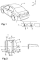
- the figure 1 illustrates a vehicle 2 equipped with two tail lights 4 each comprising a signaling module according to the invention.
- the rear lights 4 are configured to form on their outer surface 6 light images forming pictograms 8.
- pictograms may in particular indicate to the people at the rear of the vehicle 2 certain information such as the presence of a danger or the fact a pedestrian is crossing the road in front of the vehicle in question. It is understood that the pictograms may take other forms than those illustrated and provide information on other situations than those illustrated.
- the figure 2 is a schematic view in horizontal section of the left rear light of the figure 1 , it being understood that the right rear light is generally symmetrical to the left rear light.
- the rear light 4 comprises a housing 10 with an opening closed by an ice 12 forming the exit surface 6 of the rear light.
- the housing 10 in question houses a light-signaling module consisting essentially of a liquid crystal screen 14, a backlight panel 16 and an optical depolarization device, here in the form of a light diffuser 24.
- the liquid crystal screen 14 comprises a rear face 14.1 and a front face 14.2.
- the backlight panel 16 is essentially constituted by a plate 18 and light sources 20 disposed on a face of the plate arranged vis-à-vis the rear face 14.1 the liquid crystal screen 14.
- a dissipator 22, which may take the form of a radiator with cooling fins, may be arranged on the opposite face of the plate 18, in order to ensure cooling of the light sources 20.
- the latter are advantageously electroluminescence diodes .
- the depolarization optical device is a light diffuser 24. It forms a screen made of transparent or translucent material arranged vis-à-vis the front face 14.2 of the crystal screen 14. It comprises an inlet face 24.1 and an outlet face 24.2 for the light.
- One of the faces in question, in this case the exit face 24.2 has a relief with microstructures 24.3. These are voluntarily represented in an enlarged manner, for purposes of clarity of presentation, it being understood that they are substantially smaller realities, namely of the order of a micrometer. These microstructures are comparable to micro-prisms capable of deflecting, by refraction and in different directions, the light rays that meet them.
- an observer provided with polarizing glasses regardless of the orientation of the polarization direction, can perceive the light image with very little loss of brightness. Indeed, among the different light waves emitted and transmitted, only the components perpendicular to the direction of polarization of the glasses will be recalibrated by said glasses, all the components parallel to the direction of polarization not undergoing any absorption.
- the light diffuser 24 is advantageously a film of transparent or translucent plastic material, such as polycarbonate (PC) or polyester (PE), forming a substrate on which an epoxy resin is deposited and on which the relief is printed.
- films are commercially available, especially from Luminit®. They may have a thickness greater than or equal to 0.1 mm and / or less than or equal to 0.3 mm.
- the film in question can be affixed and adhered directly to the front face 14.2 of the liquid crystal screen 14. Alternatively, it can be stretched on a frame is placed at a distance from the front face 14.2 of the liquid crystal screen 14, as shown in the figure 2 .
- the light diffuser 24 may also be a plate, more rigid, in the same material as the film mentioned above. Similar to the film stretched on a frame, the plate can be remotely disposed on the front face 14.2 of the liquid crystal screen 14, as illustrated in FIG. figure 2 .
- the diffusion angle ⁇ is the total angle corresponding to the half-height width of the Gaussian distribution of a collimated source after passing through the diffuser. This angle and the above relationship do not depend on the wavelength when it is between 360 and 1600 nm.
- the light diffuser 24 may be of the elliptical type, that is to say it provides differentiated diffusion in two perpendicular directions.
- the small diffusion angle ⁇ may be greater than or equal to 10 ° and / or less than or equal to 30 °.
- the wide diffusion angle ⁇ may be greater than or equal to 30 ° and / or less than or equal to 60 °.
- the outgoing beam then has an elliptical shape with two diffusion angles ⁇ along the two perpendicular directions, one being a minimum angle and the other being an angle maximum. These angles can be estimated with the relation above.
- the depolarization optical device may also be a quarter wave retardation plate or quarter wave plate.
- a quarter wave plate also denoted blade ⁇ / 4 is a parallel-faced blade that creates a phase shift of 90 °, that is to say a delay of a quarter of a wavelength.
- the quarter-wave plate is arranged so that the angle between the output polarization of the liquid crystal screen 14 and the quarter-wave plate axis is 45 °.
- the quarter wave plate makes it possible to pass from a rectilinear polarization to an elliptical or even circular polarization.
- the light image thus depolarized can be perceived correctly by an observer wearing polarizing glasses because the polarization of such glasses is linear and is therefore not likely to absorb a substantial portion of the polarized light circular or elliptical.
Abstract
Description
- L'invention a trait au domaine de la signalisation lumineuse, plus particulièrement la signalisation lumineuse pour véhicule automobile.
- Le document de brevet publié sous le numéro
FR 3 026 689 A1 - De manière générale, les écrans à cristaux liquides utilisent la polarisation de la lumière par des filtres polarisants et la biréfringence de certains cristaux liquides en phase nématique, dont on peut faire varier l'orientation en fonction du champ électrique. Un écran à cristaux liquides est constitué de deux polariseurs dont les directions de polarisation forment un angle de 90°, disposés de chaque côté d'un sandwich, formé de deux plaques de verre enserrant des cristaux liquides. Les deux faces internes des plaques de verres comportent une matrice d'électrodes transparentes pour le noir et blanc. Pour les écrans couleur, le principe de base est le même, il nécessite cependant trois cellules par pixels et le sandwich est complété par un filtre coloré de motifs rouges, verts et bleus.
- Il s'ensuit que la lumière d'un module lumineux utilisant un écran à cristaux liquides est polarisée suivant une direction donnée, définie par le filtre polarisant de sortie de l'écran. L'utilisation de lunettes polarisantes par un observateur peut alors conduire à une occultation totale de l'image lumineuse lorsque la direction de polarisation de ladite image est perpendiculaire à la direction de polarisation des lunettes. Cette dernière est habituellement verticale, essentiellement pour filtrer les réflexions des rayons solaires sur des surfaces vitreuses, comme par exemple sur la surface d'une étendue d'eau, cette réflexion ayant pour effet de polariser la lumière suivant une direction parallèle à la surface de l'eau. Aussi, les écrans à cristaux liquides d'affichage, notamment sur les tableaux de bord de véhicules, présentent habituellement une direction de polarisation inclinée à 45°. Un observateur porteur de lunettes polarisantes verticalement va cependant percevoir l'image produite par un tel écran avec une perte de luminosité importante, à savoir de l'ordre de 50%.
- Dans le domaine de la signalisation lumineuse, plus particulièrement lorsque celle-ci a un impact direct sur la sécurité des personnes, comme c'est le cas dans la signalisation lumineuse pour véhicule automobile, l'utilisation d'écrans à cristaux liquides peut présenter des défauts de perception par des observateurs porteurs de lunettes polarisantes.
- L'invention a pour objectif de pallier au moins un des inconvénients de l'état de la technique susmentionné. Plus particulièrement, l'invention a pour objectif d'éviter des défauts de perception d'images lumineuses produites par un module lumineux utilisant un écran à cristaux liquides.
- L'invention a pour objet un module de signalisation lumineuse, notamment pour véhicule automobile, comprenant un écran à cristaux liquides avec une face arrière et une face avant ; un panneau de rétroéclairage disposé en vis-à-vis de la face arrière de l'écran à cristaux liquides, configuré pour rétroéclairer l'écran à cristaux liquides en vue de former, par transmission au travers dudit écran, une image lumineuse ; remarquable en ce que le module comprend, en outre, un dispositif optique de dépolarisation en vis-à-vis de la face avant de l'écran à cristaux liquides configuré pour annuler une polarisation rectiligne de l'image lumineuse générée par l'écran à cristaux liquides.
- Avantageusement, le dispositif optique de dépolarisation est un dépolaris eur.
- Avantageusement, le panneau de rétroéclairage s'étend sur au moins 80% de la face arrière de l'écran à cristaux liquides. Avantageusement, le panneau de rétroéclairage comprend des sources lumineuses réparties de manière homogène sur son étendue. Avantageusement, le panneau de rétroéclairage est situé à distance de la face arrière de l'écran à cristaux liquides.
- Avantageusement, l'image lumineuse comprend des pictogrammes.
- Selon une première variante de l'invention, le dispositif optique de dépolarisation est un diffuseur de lumière.
- Selon un mode avantageux de l'invention, le diffuseur de lumière forme un écran transparent ou translucide avec une face d'entrée et une face de sortie, au moins l'une desdites faces présentant un relief avec des microstructures.
- Selon un mode avantageux de l'invention, la face de l'écran transparent ou translucide présentant un relief avec des microstructures est la face de sortie.
- Selon un mode avantageux de l'invention, le diffuseur de lumière est du type circulaire.
- Selon un mode avantageux de l'invention, le diffuseur de lumière présente un angle de diffusion supérieur ou égal à 30°.
- Selon un mode avantageux de l'invention, le diffuseur de lumière est du type elliptique.
- Selon un mode avantageux de l'invention, le diffuseur de lumière présente un petit angle de diffusion supérieur ou égal à 10° et/ou un grand angle de diffusion supérieur ou égal à 60°.
- Selon un mode avantageux de l'invention, le diffuseur de lumière comprend un film ou un écran, transparent ou translucide, collé ou plaqué sur la face avant de l'écran à cristaux liquides ou tendu sur un cadre disposé à distance de la face avant de l'écran à cristaux liquides.
- Selon une autre variante de l'invention, le dispositif optique de dépolarisation est une lame à retard quart d'onde.
- Avantageusement, l'image lumineuse correspond à une fonction de lanterne pour véhicule automobile.
- L'invention a également pour objet un dispositif lumineux comprenant un boîtier avec une ouverture ; une glace fixée au boîtier de manière à fermer l'ouverture ; au moins un module de signalisation lumineuse ; remarquable en ce que le ou un des modules de signalisation lumineuse est conforme à l'invention.
- Avantageusement, le dispositif lumineux est un feu arrière de véhicule automobile.
- Les mesures de l'invention sont intéressantes en ce qu'elles assurent une bonne perception de l'image lumineuse produite par le module, et ce en particulier lorsque l'observateur porte des lunettes polarisantes, indépendamment de l'orientation des lunettes en question par rapport à la direction de polarisation du filtre polarisant de sortie de l'écran à cristaux liquides.
- D'autres caractéristiques et avantages de la présente invention seront mieux compris à l'aide de la description et des dessins parmi lesquels :
- La
figure 1 est une illustration d'un feu de signalisation arrière d'un véhicule apte à produire des images lumineuses au moyen d'un écran à cristaux liquides, comprenant un module lumineux conforme à l'invention et formant un dispositif lumineux conforme à l'invention ; - La
figure 2 est une vue schématique en coupe du dispositif lumineux de lafigure 1 . - La
figure 1 illustre un véhicule 2 équipé de deux feux arrière 4 comprenant, chacun, un module de signalisation conforme à l'invention. Les feux arrière 4 sont configurés pour former sur leur surface extérieure 6 des images lumineuses formant des pictogrammes 8. Ces pictogrammes peuvent notamment indiquer aux personnes situées à l'arrière du véhicule 2 certaines informations telles que la présence d'un danger ou encore le fait qu'un piéton est en train de traverser la route à l'avant du véhicule en question. Il est entendu que les pictogrammes peuvent prendre d'autres formes que celles illustrées et renseigner sur d'autres situations que celles illustrées. - La
figure 2 est une vue schématique en coupe horizontale du feu arrière gauche de lafigure 1 , étant entendu que le feu arrière droit est généralement symétrique au feu arrière gauche. - Le feu arrière 4 comprend un boîtier 10 avec une ouverture refermée par une glace 12 formant la surface de sortie 6 du feu arrière. Le boîtier 10 en question loge un module de signalisation lumineuse constitué essentiellement d'un écran à cristaux liquides 14, d'un panneau de rétroéclairage 16 et d'un dispositif optique de dépolarisation, ici sous la forme d'un diffuseur de lumière 24.
- Plus spécifiquement, l'écran à cristaux liquide 14 comprend une face arrière 14.1 et une face avant 14.2. Le panneau de rétroéclairage 16 est quant à lui constitué essentiellement d'une platine 18 et de sources lumineuses 20 disposées sur une face de la platine disposée en vis-à-vis de la face arrière 14.1 l'écran à cristaux liquides 14. Un dissipateur de chaleur 22, pouvant prendre la forme d'un radiateur avec des ailettes de refroidissement, peut être disposé sur la face opposée de la platine 18, en vue d'assurer un refroidissement des sources lumineuses 20. Ces dernières sont avantageusement des diodes à électroluminescence.
- Selon une première variante de réalisation, le dispositif optique de dépolarisation selon l'invention est un diffuseur de lumière 24. Il forme un écran en matériau transparent ou translucide disposé en vis-à-vis de la face avant 14.2 de l'écran à cristaux liquides 14. Il comprend une face d'entrée 24.1 et une face de sortie 24.2 pour la lumière. L'une des faces en question, dans le cas présent la face de sortie 24.2, présente un relief avec des microstructures 24.3. Celles-ci sont volontairement représentées de manière agrandie, à des fins de clarté d'exposé, étant entendu qu'elles sont en réalités sensiblement plus petites, à savoir de l'ordre du micromètre. Ces microstructures sont assimilables à des micro-prismes aptes à dévier, par réfraction et dans différentes directions, les rayons lumineux qui les rencontrent. Par voie de conséquence, les rayons lumineux sortant de la face avant 14.2 de l'écran à cristaux liquides, polarisés de manière linéaire suivant la direction de polarisation du filtre polarisateur de sortie de l'écran, sont alors dépolarisés au travers du dispositif diffuseur de lumière 24. De cette façon, un observateur muni de lunettes polarisantes, indépendamment de l'orientation de la direction de polarisation, pourra percevoir l'image lumineuse avec très peu de perte de luminosité. En effet, parmi les différentes ondes lumineuses émises et transmises, seules les composantes perpendiculaires à la direction de polarisation des lunettes seront recalées par lesdites lunettes, toutes les composantes parallèles à la direction de polarisation ne subissant aucune absorption.
- Le diffuseur de lumière 24 est avantageusement un film en matériau plastique transparent ou translucide, tel que du polycarbonate (PC) ou du polyester (PE), formant un substrat sur lequel une résine époxy est déposée et sur laquelle le relief est imprimé. De tels films sont commercialement disponibles notamment auprès de la société Luminit®. Ils peuvent présenter une épaisseur supérieure ou égale à 0.1mm et/ou inférieure ou égale à 0.3mm. Le film en question peut être apposé et adhéré directement sur la face avant 14.2 de l'écran à cristaux liquides 14. Alternativement, il peut être tendu sur un cadre est disposé à distance la face avant 14.2 de l'écran à cristaux liquides 14, comme illustré à la
figure 2 . Le diffuseur de lumière 24 peut également être une plaque, davantage rigide, dans le même matériau que le film évoqué ci-avant. Similairement au film tendu sur un cadre, la plaque peut être disposée à distance la face avant 14.2 de l'écran à cristaux liquides 14, comme illustré à lafigure 2 . - Le diffuseur de lumière 24 peut être du type circulaire, c'est-à-dire qu'il assure une diffusion identique dans toutes les positions angulaires par rapport à un axe optique des rayons lumineux entrant. Il peut présenter un angle de diffusion circulaire Δ supérieur ou égal à 30°. Dans le cas d'un faisceau lumineux entrant divergeant suivant un angle α, l'angle de diffusion β à la sortie du diffuseur de lumière 24peut être estimé suivant la relation suivante :

- Suivant cette relation, l'angle de diffusion β est l'angle total correspondant à la largeur à mi-hauteur de la distribution gaussienne d'une source collimatée après avoir traversé le diffuseur. Cet angle et la relation ci-avant ne dépendent pas de la longueur d'onde lorsque celle-ci est comprise entre 360 et 1600nm.
- Le diffuseur de lumière 24 peut être du type elliptique, c'est-à-dire qu'il assure une diffusion différenciée dans deux directions perpendiculaires. Le petit angle de diffusion Δ peut être supérieur ou égal à 10° et/ou inférieur ou égal à 30°. Le grand angle de diffusion Δ peut être supérieur ou égal à 30° et/ou inférieur ou égal à 60°. Dans le cas d'un faisceau lumineux entrant, divergeant suivant un angle α, le faisceau sortant présente alors une forme elliptique avec deux angles de diffusion β suivant les deux directions perpendiculaires, l'un étant un angle minimum et l'autre étant un angle maximum. Ces angles peuvent être estimés avec la relation ci-avant.
- Selon une autre variante de réalisation, le dispositif optique de dépolarisation peut également être une lame à retard quart d'onde ou lame quart d'onde. Une lame quart d'onde, également notée lame λ/4, est une lame à face parallèle qui crée un déphasage de 90°, c'est-à-dire un retard d'un quart de longueur d'onde. Avantageusement, la lame quart d'onde est disposée de sorte que l'angle entre la polarisation de sortie de l'écran à cristaux liquide 14 et l'axe de la lame quart d'onde est de 45°.
- La lame quart d'onde permet de passer d'une polarisation rectiligne à une polarisation elliptique voire circulaire. L'image lumineuse ainsi dépolarisée pourra être perçue correctement par un observateur portant des lunettes polarisantes car la polarisation de telles lunettes est linéaire et n'est donc pas susceptible d'absorber une partie substantielle de la lumière polarisée de manière circulaire ou elliptique.
Claims (11)
- Module de signalisation lumineuse, notamment pour véhicule automobile (2), comprenant :- un écran à cristaux liquides (14) avec une face arrière (14.1) et une face avant (14.2) ;- un panneau de rétroéclairage (16) disposé en vis-à-vis de la face arrière (14.1) de l'écran à cristaux liquides (14), configuré pour rétroéclairer l'écran à cristaux liquides (14) en vue de former, par transmission au travers dudit écran, une image lumineuse ;caractérisé en ce que le module comprend, en outre :- un dispositif optique de dépolarisation en vis-à-vis de la face avant (14.2) de l'écran à cristaux liquides (14), configuré pour annuler une polarisation rectiligne de l'image lumineuse générée par l'écran à cristaux liquides (14).
- Module de signalisation lumineuse selon la revendication 1, caractérisé en ce que le dispositif optique de dépolarisation est un diffuseur de lumière (24).
- Module de signalisation lumineuse selon la revendication 2, caractérisé en ce que le diffuseur de lumière (24) forme un écran transparent ou translucide avec une face d'entrée (24.1) et une face de sortie (24.2), au moins l'une desdites faces d'entrée (24.1) et face de sortie (24.2)présentant un relief avec des microstructures (24.3).
- Module de signalisation lumineuse selon la revendication 3, caractérisé en ce que la face de l'écran transparent ou translucide présentant un relief avec des microstructures (24.3) est la face de sortie (24.2).
- Module de signalisation lumineuse selon l'une des revendications 2 à 4, caractérisé en ce que le diffuseur de lumière (24) est du type circulaire.
- Module de signalisation lumineuse selon la revendication 5, caractérisé en ce que le diffuseur de lumière (24) présente un angle de diffusion Δ supérieur ou égal à 30°.
- Module de signalisation lumineuse selon l'une des revendications 2 à 6, caractérisé en ce que le diffuseur de lumière (24) est du type elliptique.
- Module de signalisation lumineuse selon la revendication 7, caractérisé en ce que le diffuseur de lumière (24) présente un petit angle de diffusion Δ supérieur ou égal à 10° et/ou un grand angle de diffusion Δ supérieur ou égal à 60°.
- Module de signalisation lumineuse selon l'une des revendications 2 à 8, caractérisé en ce que le diffuseur de lumière (24) comprend un film transparent ou translucide collé sur la face avant (14.2) de l'écran à cristaux liquides (14) ou tendu sur un cadre disposé à distance de la face avant (14.2) de l'écran à cristaux liquides (14).
- Module de signalisation lumineuse selon la revendication 1, caractérisé en ce que le dispositif optique de dépolarisation est un lame à retard quart d'onde.
- Dispositif lumineux (4) comprenant :- un boîtier (10) avec une ouverture ;- une glace (12) fixée au boîtier (10) de manière à fermer l'ouverture ;- au moins un module de signalisation lumineuse ;caractérisé en ce que
le ou un des modules de signalisation lumineuse est conforme à l'une des revendications 1 à 10.
Applications Claiming Priority (1)
| Application Number | Priority Date | Filing Date | Title |
|---|---|---|---|
| FR1852727A FR3079599A1 (fr) | 2018-03-29 | 2018-03-29 | Dispositif de signalisation lumineuse avec ecran lcd |
Publications (1)
| Publication Number | Publication Date |
|---|---|
| EP3547009A1 true EP3547009A1 (fr) | 2019-10-02 |
Family
ID=62948216
Family Applications (1)
| Application Number | Title | Priority Date | Filing Date |
|---|---|---|---|
| EP19165338.5A Withdrawn EP3547009A1 (fr) | 2018-03-29 | 2019-03-26 | Dispositif de signalisation lumineuse avec ecran lcd |
Country Status (4)
| Country | Link |
|---|---|
| US (1) | US10677411B2 (fr) |
| EP (1) | EP3547009A1 (fr) |
| CN (1) | CN110332499A (fr) |
| FR (1) | FR3079599A1 (fr) |
Families Citing this family (2)
| Publication number | Priority date | Publication date | Assignee | Title |
|---|---|---|---|---|
| DE202022001988U1 (de) * | 2021-10-26 | 2022-10-12 | Hyundai Mobis Co., Ltd. | Kommunikationsvorrichtung für Fahrzeug |
| FR3137438A1 (fr) * | 2022-06-30 | 2024-01-05 | Valeo Vision | Module lumineux avec affichage par led optimisé pour application automobile |
Citations (6)
| Publication number | Priority date | Publication date | Assignee | Title |
|---|---|---|---|---|
| DE710250C (de) * | 1936-10-31 | 1941-09-08 | Dr Med Paul Wiemer | Vorrichtung zur Erzeugung blendungsfreien Scheinwerferlichtes durch Zirkularpolarisation des Lichtes |
| US6101032A (en) * | 1994-04-06 | 2000-08-08 | 3M Innovative Properties Company | Light fixture having a multilayer polymeric film |
| FR2846756A1 (fr) * | 2002-11-04 | 2004-05-07 | Pechon Stephane Jean Martin Le | Dispositif de vision nocturne destine a la conduite |
| DE102013113807A1 (de) * | 2013-12-11 | 2015-06-11 | Hella Kgaa Hueck & Co. | Beleuchtungseinrichtung für ein Kraftfahrzeug |
| EP3205928A1 (fr) * | 2016-02-05 | 2017-08-16 | Automotive Lighting Reutlingen GmbH | Phare de véhicule automobile équipé d'un élément structurel à matrice à cristaux liquides |
| EP3208531A2 (fr) * | 2016-02-19 | 2017-08-23 | Automotive Lighting Reutlingen GmbH | Phare de véhicule automobile comprenant un affichage à cristaux liquides |
Family Cites Families (9)
| Publication number | Priority date | Publication date | Assignee | Title |
|---|---|---|---|---|
| US7581859B2 (en) * | 2005-09-14 | 2009-09-01 | Donnelly Corp. | Display device for exterior rearview mirror |
| WO2008051910A2 (fr) * | 2006-10-24 | 2008-05-02 | Donnelly Corporation | Dispositif d'affichage pour un rétroviseur |
| CN101218469A (zh) * | 2005-07-08 | 2008-07-09 | 皇家飞利浦电子股份有限公司 | 用于产生具有电可变散射图案的光模块及其作为多用途光的使用 |
| JP5238124B2 (ja) * | 2005-09-16 | 2013-07-17 | スタンレー電気株式会社 | 液晶光学素子及びその製造方法並びにそれを使用した車両用灯具 |
| US8836888B2 (en) * | 2009-12-15 | 2014-09-16 | Gentex Corporation | Modular light source/electronics and automotive rearview assemblies using the same |
| US9016910B2 (en) * | 2011-06-10 | 2015-04-28 | Adac Plastics, Inc. | Vehicular component incorporating concealable indicia with controlled light transmission |
| DE102012112127B4 (de) * | 2012-12-12 | 2024-02-08 | HELLA GmbH & Co. KGaA | Lichtmodul mit LCD-Blende für einen Scheinwerfer eines Fahrzeugs |
| CN107107807B (zh) * | 2014-11-07 | 2021-03-19 | 大日本印刷株式会社 | 照明装置 |
| KR101859047B1 (ko) * | 2015-06-24 | 2018-05-17 | 엘지전자 주식회사 | 헤드 램프, 차량 운전 보조 장치 및 차량 |
-
2018
- 2018-03-29 FR FR1852727A patent/FR3079599A1/fr active Pending
-
2019
- 2019-03-26 EP EP19165338.5A patent/EP3547009A1/fr not_active Withdrawn
- 2019-03-29 US US16/369,636 patent/US10677411B2/en active Active
- 2019-03-29 CN CN201910256471.1A patent/CN110332499A/zh active Pending
Patent Citations (6)
| Publication number | Priority date | Publication date | Assignee | Title |
|---|---|---|---|---|
| DE710250C (de) * | 1936-10-31 | 1941-09-08 | Dr Med Paul Wiemer | Vorrichtung zur Erzeugung blendungsfreien Scheinwerferlichtes durch Zirkularpolarisation des Lichtes |
| US6101032A (en) * | 1994-04-06 | 2000-08-08 | 3M Innovative Properties Company | Light fixture having a multilayer polymeric film |
| FR2846756A1 (fr) * | 2002-11-04 | 2004-05-07 | Pechon Stephane Jean Martin Le | Dispositif de vision nocturne destine a la conduite |
| DE102013113807A1 (de) * | 2013-12-11 | 2015-06-11 | Hella Kgaa Hueck & Co. | Beleuchtungseinrichtung für ein Kraftfahrzeug |
| EP3205928A1 (fr) * | 2016-02-05 | 2017-08-16 | Automotive Lighting Reutlingen GmbH | Phare de véhicule automobile équipé d'un élément structurel à matrice à cristaux liquides |
| EP3208531A2 (fr) * | 2016-02-19 | 2017-08-23 | Automotive Lighting Reutlingen GmbH | Phare de véhicule automobile comprenant un affichage à cristaux liquides |
Also Published As
| Publication number | Publication date |
|---|---|
| CN110332499A (zh) | 2019-10-15 |
| US20190301703A1 (en) | 2019-10-03 |
| US10677411B2 (en) | 2020-06-09 |
| FR3079599A1 (fr) | 2019-10-04 |
Similar Documents
| Publication | Publication Date | Title |
|---|---|---|
| EP1730580B1 (fr) | Element de vision transparent et polarisant ayant des zones associees a des filtres de polarisation orientes respectivement verticalement et horizontalement | |
| CA2146902A1 (fr) | Afficheur a cristaux liquides a caracteristiques de visualisation ameliorees | |
| FR3028963A1 (fr) | Systeme de protection pour afficheur, notamment tete haute, et afficheur associe | |
| EP3547009A1 (fr) | Dispositif de signalisation lumineuse avec ecran lcd | |
| EP1807727B1 (fr) | Afficheur ophtalmique comportant une lentille ophtalmique et un imageur optique | |
| CN105527708A (zh) | 防尘罩组件及具备此的抬头显示装置 | |
| FR2982989A1 (fr) | Dispositif actif de juxtaposition d'ecran et systeme de visualisation associe | |
| CN108535867A (zh) | 全时抬头显示系统 | |
| US9511715B2 (en) | Backlighting assembly for display for reducing cross-hatching | |
| EP3132308A1 (fr) | Systeme de generation d'image pour afficheur tete haute et afficheur tete haute associe pour vehicule automobile | |
| EP3752767B1 (fr) | Feu de signalisation compact à affichage de pictogramme | |
| FR3054329B1 (fr) | Dispositif de generation d'image et afficheur tete haute comprenant un tel dispositif de generation d'image | |
| EP0828966A1 (fr) | Procedes et dispositifs de polarisation pour l'amelioration de la visibilite notamment dans les mobiles | |
| FR3075404A1 (fr) | Dispositif de generation d'images et afficheur tete haute associe | |
| FR3058237B1 (fr) | Afficheur | |
| EP3807698B1 (fr) | Appareil de projection destiné à un système d'affichage tête haute pour conducteur de véhicule automobile et système correspondant | |
| WO2021048480A1 (fr) | Élément de couverture de l'ouverture de projection d'un dispositif d'affichage tête-haute | |
| JP2004170737A (ja) | 車両用表示装置 | |
| FR3092673A1 (fr) | Ensemble d’affichage et combiné d’instruments | |
| FR3077649A1 (fr) | Dispositif de generation d'images et afficheur tete haute comprenant un tel dispositif | |
| FR3082011A1 (fr) | Dispositif de generation d'images et afficheur tete-haute comprenant un tel dispositif | |
| FR3083330A1 (fr) | Dispositif d'affichage tete haute | |
| FR3097977A1 (fr) | Dispositif d’affichage tête haute | |
| FR2872588A1 (fr) | Systeme d'illumination pour imageur et projecteur correspondant | |
| FR3064080A1 (fr) | Afficheur tete haute adapte au port de lunettes polarisantes |
Legal Events
| Date | Code | Title | Description |
|---|---|---|---|
| PUAI | Public reference made under article 153(3) epc to a published international application that has entered the european phase |
Free format text: ORIGINAL CODE: 0009012 |
|
| STAA | Information on the status of an ep patent application or granted ep patent |
Free format text: STATUS: THE APPLICATION HAS BEEN PUBLISHED |
|
| AK | Designated contracting states |
Kind code of ref document: A1 Designated state(s): AL AT BE BG CH CY CZ DE DK EE ES FI FR GB GR HR HU IE IS IT LI LT LU LV MC MK MT NL NO PL PT RO RS SE SI SK SM TR |
|
| AX | Request for extension of the european patent |
Extension state: BA ME |
|
| STAA | Information on the status of an ep patent application or granted ep patent |
Free format text: STATUS: REQUEST FOR EXAMINATION WAS MADE |
|
| 17P | Request for examination filed |
Effective date: 20200422 |
|
| RBV | Designated contracting states (corrected) |
Designated state(s): AL AT BE BG CH CY CZ DE DK EE ES FI FR GB GR HR HU IE IS IT LI LT LU LV MC MK MT NL NO PL PT RO RS SE SI SK SM TR |
|
| STAA | Information on the status of an ep patent application or granted ep patent |
Free format text: STATUS: EXAMINATION IS IN PROGRESS |
|
| 17Q | First examination report despatched |
Effective date: 20200904 |
|
| STAA | Information on the status of an ep patent application or granted ep patent |
Free format text: STATUS: EXAMINATION IS IN PROGRESS |
|
| STAA | Information on the status of an ep patent application or granted ep patent |
Free format text: STATUS: THE APPLICATION IS DEEMED TO BE WITHDRAWN |
|
| 18D | Application deemed to be withdrawn |
Effective date: 20210316 |