EP3547002A2 - Linsenvorrichtung und bildaufnahmevorrichtung - Google Patents
Linsenvorrichtung und bildaufnahmevorrichtung Download PDFInfo
- Publication number
- EP3547002A2 EP3547002A2 EP19166057.0A EP19166057A EP3547002A2 EP 3547002 A2 EP3547002 A2 EP 3547002A2 EP 19166057 A EP19166057 A EP 19166057A EP 3547002 A2 EP3547002 A2 EP 3547002A2
- Authority
- EP
- European Patent Office
- Prior art keywords
- lens unit
- focus
- image pickup
- focus lens
- move
- Prior art date
- Legal status (The legal status is an assumption and is not a legal conclusion. Google has not performed a legal analysis and makes no representation as to the accuracy of the status listed.)
- Withdrawn
Links
- 238000003384 imaging method Methods 0.000 claims abstract description 23
- 230000003287 optical effect Effects 0.000 claims description 54
- 230000008859 change Effects 0.000 claims description 47
- 239000004606 Fillers/Extenders Substances 0.000 claims description 9
- 238000003780 insertion Methods 0.000 claims description 5
- 230000037431 insertion Effects 0.000 claims description 5
- 238000012937 correction Methods 0.000 description 20
- 238000000034 method Methods 0.000 description 10
- 238000010586 diagram Methods 0.000 description 8
- 238000012545 processing Methods 0.000 description 8
- 230000000694 effects Effects 0.000 description 5
- 238000001514 detection method Methods 0.000 description 4
- 230000006870 function Effects 0.000 description 4
- 238000011084 recovery Methods 0.000 description 3
- 238000004519 manufacturing process Methods 0.000 description 2
- 238000012986 modification Methods 0.000 description 2
- 230000004048 modification Effects 0.000 description 2
- 230000005484 gravity Effects 0.000 description 1
- 230000007246 mechanism Effects 0.000 description 1
- 238000012544 monitoring process Methods 0.000 description 1
- 229910052709 silver Inorganic materials 0.000 description 1
- 239000004332 silver Substances 0.000 description 1
- -1 silver halide Chemical class 0.000 description 1
- 230000006641 stabilisation Effects 0.000 description 1
- 238000011105 stabilization Methods 0.000 description 1
- 230000007704 transition Effects 0.000 description 1
Images


Classifications
-
- G—PHYSICS
- G02—OPTICS
- G02B—OPTICAL ELEMENTS, SYSTEMS OR APPARATUS
- G02B7/00—Mountings, adjusting means, or light-tight connections, for optical elements
- G02B7/02—Mountings, adjusting means, or light-tight connections, for optical elements for lenses
- G02B7/04—Mountings, adjusting means, or light-tight connections, for optical elements for lenses with mechanism for focusing or varying magnification
- G02B7/10—Mountings, adjusting means, or light-tight connections, for optical elements for lenses with mechanism for focusing or varying magnification by relative axial movement of several lenses, e.g. of varifocal objective lens
-
- G—PHYSICS
- G02—OPTICS
- G02B—OPTICAL ELEMENTS, SYSTEMS OR APPARATUS
- G02B7/00—Mountings, adjusting means, or light-tight connections, for optical elements
- G02B7/02—Mountings, adjusting means, or light-tight connections, for optical elements for lenses
- G02B7/04—Mountings, adjusting means, or light-tight connections, for optical elements for lenses with mechanism for focusing or varying magnification
- G02B7/09—Mountings, adjusting means, or light-tight connections, for optical elements for lenses with mechanism for focusing or varying magnification adapted for automatic focusing or varying magnification
-
- G—PHYSICS
- G02—OPTICS
- G02B—OPTICAL ELEMENTS, SYSTEMS OR APPARATUS
- G02B13/00—Optical objectives specially designed for the purposes specified below
- G02B13/24—Optical objectives specially designed for the purposes specified below for reproducing or copying at short object distances
-
- G—PHYSICS
- G02—OPTICS
- G02B—OPTICAL ELEMENTS, SYSTEMS OR APPARATUS
- G02B15/00—Optical objectives with means for varying the magnification
- G02B15/14—Optical objectives with means for varying the magnification by axial movement of one or more lenses or groups of lenses relative to the image plane for continuously varying the equivalent focal length of the objective
- G02B15/16—Optical objectives with means for varying the magnification by axial movement of one or more lenses or groups of lenses relative to the image plane for continuously varying the equivalent focal length of the objective with interdependent non-linearly related movements between one lens or lens group, and another lens or lens group
-
- G—PHYSICS
- G02—OPTICS
- G02B—OPTICAL ELEMENTS, SYSTEMS OR APPARATUS
- G02B27/00—Optical systems or apparatus not provided for by any of the groups G02B1/00 - G02B26/00, G02B30/00
- G02B27/64—Imaging systems using optical elements for stabilisation of the lateral and angular position of the image
- G02B27/646—Imaging systems using optical elements for stabilisation of the lateral and angular position of the image compensating for small deviations, e.g. due to vibration or shake
-
- G—PHYSICS
- G02—OPTICS
- G02B—OPTICAL ELEMENTS, SYSTEMS OR APPARATUS
- G02B7/00—Mountings, adjusting means, or light-tight connections, for optical elements
- G02B7/02—Mountings, adjusting means, or light-tight connections, for optical elements for lenses
- G02B7/04—Mountings, adjusting means, or light-tight connections, for optical elements for lenses with mechanism for focusing or varying magnification
- G02B7/10—Mountings, adjusting means, or light-tight connections, for optical elements for lenses with mechanism for focusing or varying magnification by relative axial movement of several lenses, e.g. of varifocal objective lens
- G02B7/102—Mountings, adjusting means, or light-tight connections, for optical elements for lenses with mechanism for focusing or varying magnification by relative axial movement of several lenses, e.g. of varifocal objective lens controlled by a microcomputer
-
- G—PHYSICS
- G02—OPTICS
- G02B—OPTICAL ELEMENTS, SYSTEMS OR APPARATUS
- G02B7/00—Mountings, adjusting means, or light-tight connections, for optical elements
- G02B7/28—Systems for automatic generation of focusing signals
-
- G—PHYSICS
- G03—PHOTOGRAPHY; CINEMATOGRAPHY; ANALOGOUS TECHNIQUES USING WAVES OTHER THAN OPTICAL WAVES; ELECTROGRAPHY; HOLOGRAPHY
- G03B—APPARATUS OR ARRANGEMENTS FOR TAKING PHOTOGRAPHS OR FOR PROJECTING OR VIEWING THEM; APPARATUS OR ARRANGEMENTS EMPLOYING ANALOGOUS TECHNIQUES USING WAVES OTHER THAN OPTICAL WAVES; ACCESSORIES THEREFOR
- G03B13/00—Viewfinders; Focusing aids for cameras; Means for focusing for cameras; Autofocus systems for cameras
- G03B13/32—Means for focusing
- G03B13/34—Power focusing
- G03B13/36—Autofocus systems
-
- H—ELECTRICITY
- H04—ELECTRIC COMMUNICATION TECHNIQUE
- H04N—PICTORIAL COMMUNICATION, e.g. TELEVISION
- H04N23/00—Cameras or camera modules comprising electronic image sensors; Control thereof
- H04N23/60—Control of cameras or camera modules
- H04N23/67—Focus control based on electronic image sensor signals
Definitions
- the present invention relates to a lens apparatus and an image pickup apparatus.
- a zoom lens configured to perform focusing and zooming by moving various lens units along an optical axis.
- a zoom lens including, in order from an object side to an image side: a focus lens unit, which is stationary for zooming, and is configured to perform focusing by being moved partially or entirely; a zoom lens unit formed of a magnification varying system and a compensation system; and an imaging lens unit for imaging.
- the zoom lens has the focus lens unit arranged closest to the object side, and hence a position of the focus lens unit corresponding to an object distance is determined irrespective of a zooming state. Thus, focus control corresponding to the zooming state is not required.
- zoom lens configured to move a zoom lens unit by rotation of a cam in order to enable high-speed manual zooming.
- the focus lens unit arranged closest to the object side and the zoom lens unit to be moved by a cam mechanism are both suitable for a manual operation.
- a zoom lens of a manual operation type is preferred by professionals due to its high operability, but it is difficult to correct a deviation of a focus position due to a manufacturing error.
- the correction of the deviation of the focus position performed in Japanese Patent Application Laid-Open No. H10-186209 involves moving the imaging lens unit partially, and the macro image pickup performed in Japanese Patent Publication No. S58-1401 involves moving the imaging lens unit partially or entirely.
- the imaging lens unit can have a large number of functions by including an image stabilization lens unit and an extender lens unit. In such a case, it is desired to perform the above-mentioned focus adjustment and the above-mentioned macro image pickup by the movement of the same lens unit.
- This disclosure provides, for example, a lens apparatus advantageous in focus adjustment and macro image pickup by movement of a lens unit common therefore.
- a lens apparatus including: a first lens unit arranged closest to an object side and configured not to move for zooming; a zoom lens unit configured to move for zooming; an aperture stop; and an imaging lens unit arranged closest to an image side, wherein the first lens unit includes a first focus lens unit configured to move for focusing, wherein the imaging lens unit includes a second focus lens unit configured to move for focusing and to move for macro image pickup , and wherein the lens apparatus includes a controller configured to control a position of the second focus lens unit for the macro image pickup based on a state of at least one of the first focus lens unit, the zoom lens unit, and the aperture stop.
- a zoom lens in one embodiment of the present invention includes a first lens unit arranged closest to an object side, which is stationary for zooming, a zoom lens unit formed of magnification varying system lenses and adjustment system lenses, an aperture stop, and an imaging lens unit arranged closest to an image side.
- the first lens unit includes a first focus lens unit configured to perform a focus adjustment by being moved partially or entirely
- the imaging lens unit includes a second focus lens unit configured to perform a focus adjustment by being moved partially or entirely.
- the zoom lens includes a macro operating unit (operating unit) configured to perform macro image pickup, and has a correction table for at least any one of focus deviations caused by changes in respective optical parameters of a zoom, a focus, and an aperture stop.
- a macro operating unit operating unit
- the zoom lens has a correction table for at least any one of focus deviations caused by changes in respective optical parameters of a zoom, a focus, and an aperture stop.
- the focus adjustment is performed by position control of the second focus lens unit based on the correction table, and the second focus lens unit is moved by an operation of the macro operating unit at a time of macro image pickup.
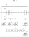
- FIG. 1 is a configuration diagram of a main portion of a zoom lens relating to a first embodiment of the present invention.
- a zoom lens 100 has a lens section including a focus part UF, a zoom part UZ, and an aperture stop UI.
- the zoom lens 100 includes a focus obtaining unit 101 configured to obtain a position of a focus lens, a zoom obtaining unit 102 configured to obtain a position of a zoom lens, and an iris obtaining unit 103 configured to obtain a position (state) of an aperture stop.
- the obtaining units 101 to 103 are each formed of an encoder, a potentiometer, a photosensor, or other such detector.
- a calculation unit 110 is a calculation circuit (CPU) (correction unit) configured to perform different kinds of control on the zoom lens.
- a movement controller 120 is a controller configured to control driving of the second focus lens unit, and a second focus driving unit 150 is a driving unit configured to drive the second focus lens unit.
- a macro operating unit 130 is an operating unit configured to operate the driving of the second focus lens unit at times of macro image pickup and bokeh image pickup (bokeh imaging, blur image pickup, blur imaging).
- a memory unit 111 stores a correction table relating to a movement amount of the second focus lens unit, which is required for correcting a focus deviation caused by a change in each of the optical parameters of a focus, a zoom, and an aperture stop.
- a movement amount f2 of a second focus movable lens unit in a macro operation is determined based on Expression (1), where "m” represents a movement amount to be used by the macro operating unit, and “mp” represents a movement amount required for completely correcting the focus deviation caused by the change in each of the optical parameters of the zoom, the focus, and the aperture stop.
- f 2 m + mp 1
- Conditional Expression (2) be Conditional Expression (2a). 0.8 ⁇ mp 1 / mp ⁇ 1.2
- Conditional Expression (2) be Conditional Expression (2b).
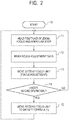
- FIG. 2 is a flow chart relating to driving of the second focus movable lens unit of the zoom lens in the first embodiment. Processing is started from Step 10.
- the calculation unit 110 obtains different kinds of optical parameters including positions and states of the focus, the zoom, and the aperture stop from the focus obtaining unit 101, the zoom obtaining unit 102, and the iris obtaining unit 103, respectively (Step 11).
- the calculation unit 110 reads a correction amount corresponding to each kind of optical parameter, which relates to the driving of the second focus movable lens unit, from the correction table stored in the memory unit 111 (Step 12).
- a correction amount corresponding to each kind of optical parameter which relates to the driving of the second focus movable lens unit
- the neighbor value nearest to each kind of optical parameter within the table may be employed as it is, or an interpolation value may be employed by being obtained by interpolation processing as appropriate from values near the neighbor value.
- the calculation unit 110 outputs the movement amount of the second focus lens unit corresponding to the correction amount to the movement controller 120.
- the second focus driving unit 150 drives the second focus lens unit to move along an optical axis, to thereby perform a focus adjustment (Step 13).
- the movement controller 120 reads a signal of the macro operating unit 130 (Step 14).
- the driving of the second focus lens unit is controlled in the above-mentioned manner, to thereby be able to start normal image pickup smoothly without going out of focus when recovering from macro image pickup to normal image pickup even in a case where each of the optical parameters of the zoom, the focus, and the aperture stop has changed since before macro start.
- the second focus movable lens unit is stopped when the macro operation is performed.
- the second focus lens unit when a shift is made from the macro image pickup to the normal image pickup, the second focus lens unit return to the position at the start of the macro operation, and perform the focus adjustment for the change in each of the optical parameters.
- the movement of the second focus lens unit can be clearly distinguished between the movement involved in the macro image pickup and the movement involved in the focus adjustment with ease, and the focus adjustment for the change in each of the optical parameters can be controlled more easily.
- FIG. 3 is a configuration diagram of a main portion of a zoom lens relating to a third embodiment of the present invention.
- the zoom lens in the third embodiment includes an extender part UE capable of being inserted into and removed from the lens section of the zoom lens 100 and an extender obtaining unit 155 for insertion and removal of an extender.
- the zoom lens in the third embodiment further includes a temperature obtaining unit (temperature detector) 156 configured to detect a temperature change and a posture obtaining unit 157 configured to detect a posture (posture difference) of arrangement of a zoom lens with respect to a gravity direction.
- a temperature obtaining unit temperature detector
- a posture obtaining unit 157 configured to detect a posture (posture difference) of arrangement of a zoom lens with respect to a gravity direction.
- the zoom lens include an extender lens unit, which is capable of being inserted into and removed from an optical path, and is configured to shift a focal length, include at least one temperature detection unit, and include at least one detection unit for detecting a posture of the zoom lens.
- the zoom lens may include a correction table for correcting an influence exerted on the focus deviation by each of the optical parameters including the state of the insertion or removal of the extender lens unit into/from the optical path, its temperature, and its posture, to thereby move the second focus movable lens unit based on the correction table depending on the change in each of the optical parameters.
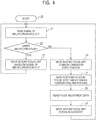
- FIG. 4 is a flow chart relating to the third embodiment. Processing is started from Step 20.
- the movement controller 120 reads the signal of the macro operating unit from the macro operating unit 130 (Step 21).
- the movement controller 120 drives the second focus driving unit 150 based on the signal of the macro operating unit to move the second focus lens unit along the optical axis, to thereby perform the macro image pickup or the bokeh image pickup (Step 22 and Step 23). Then, the procedure returns to Step 21 to continue the flow.
- the movement controller 120 moves the second focus lens unit to a start position (Step 24).
- a temperature detection apparatus may use a plurality of apparatus in combination to perform an adjustment suitable for an image pickup environment by, for example, handling a heat source from one direction or detecting whether the temperature is steady or transitional even in a case of the same temperature.
- a plurality of detection apparatus may be used as well to improve accuracy.
- the calculation unit 110 reads the correction amount corresponding to each kind of optical parameter from the correction table stored in the memory unit 111 (Step 26).
- the calculation unit 110 transmits the movement amount of the second focus lens unit corresponding to the correction amount to the movement controller 120, and causes the movement controller 120 to drive the second focus driving unit 150 to move the second focus lens unit along the optical axis, to thereby perform the focus adjustment (Step 27).
- the zoom lens By configuring the zoom lens in this manner, it is possible to perform focus adjustments in consideration of influences of changes of the state of the insertion and removal of the extender lens unit into/from the optical path, the temperature during image pickup, and the posture difference during image pickup.
- FIG. 5 is a configuration diagram of a main portion of a zoom lens relating to a fourth embodiment of the present invention.
- the zoom lens in the fourth embodiment includes an ON/OFF switch operating unit 140 configured to switch between on and off of the focus adjustment for the change in each of the optical parameters.
- the movement amount f2 of the second focus movable lens unit in the macro operation is determined based on Expression (3), where "m” represents an amount of movement from the normal image pickup position to a macro image pickup position to be performed by the macro operating unit, and “mf' represents a movement amount based on correction of a change of an f-number caused by a change in each of the optical parameters of the zoom, the focus, and the aperture stop.
- f 2 m + mf
- a movement amount p2 based on the correction amount of the change of the f-number caused by the change in each of the optical parameters of the aperture stop is determined in the following manner.
- the change rate ⁇ f2 of the movement amount of the second focus movable lens unit caused by the change in optical parameter, which corresponds to the change rate of the focal length, is expressed by Expression (7), where "m” represents the amount of the movement of the second focus lens unit from the normal image pickup position to the macro image pickup position to be performed by the macro operating unit 130, and “mf” represents the movement amount based on the correction of the change of the f-number caused by the change in each of the optical parameters of the zoom, the focus, and the aperture stop.
- ⁇ f 2 m + mf / m
- the movement amount "mf' for compensating an influence of the change of the f-number caused by the change in each of the optical parameters on the bokeh diameter is determined so as to satisfy Conditional Expression (8). 0.5 ⁇ ⁇ f 2 / ⁇ fno ⁇ 1.5
- the movement amount "mf' is determined so as to satisfy the following conditional expression: 0.5 ⁇ m + mf / m / ⁇ Fno ⁇ 1.5 , to thereby be able to produce the effects of the present invention. It is preferred that Conditional Expression (8) satisfy the following conditional expression. 0.8 ⁇ ⁇ f 2 / ⁇ Fno ⁇ 1.2
- Conditional Expression (2) defines a relationship between the f-number and the movement amount of the second focus movable lens unit.
- a switching apparatus configured to turn on or off a focus adjustment be provided to the zoom lens, a zoom operating apparatus, or a focus operating apparatus to turn on or off the focus adjustment performed by moving the second focus movable lens unit. This can prevent an erroneous operation due to added noise and unintentional movement of the photographer.
- FIG. 6 is a flow chart relating to the fourth embodiment. Processing is started from Step 30.
- the calculation unit 110 reads a signal of the ON/OFF switch operating unit 140, and determines whether or not to perform a focus adjustment (Step 31).
- the respective obtaining units 101 to 103 read the optical parameters of the focus, the zoom, and the aperture stop, respectively, and transmit the read optical parameters to the calculation unit 110 (Step 32).
- the calculation unit 110 reads the correction amount corresponding to each kind of optical parameter from the correction table stored in the memory unit 111 (Step 33).
- the calculation unit 110 transmits the movement amount of the second focus lens unit corresponding to the correction amount to the movement controller 120, and causes the movement controller 120 to drive the second focus driving unit 150 to move the second focus lens unit along the optical axis, to thereby perform the focus adjustment (Step 34).
- the movement controller 120 reads the signal of the macro operating unit 130 to determine whether or not the zoom lens is under the macro operation (Step 35).
- the movement controller 120 moves the second focus lens unit so as to satisfy the following expression (Step 36). 0.5 ⁇ ⁇ f 2 / ⁇ Fno ⁇ 1.5
- the movement controller 120 determines whether or not the position of the second focus lens unit has passed through the position appropriate for the focus adjustment amount (Step 37).
- the second focus driving unit 150 stops the driving to stop the movement of the second focus lens unit (Step 38). Then, the procedure returns to Step 31 to continue the flow. Meanwhile, when the position of the second focus lens unit has not passed through the position appropriate for the focus adjustment amount, the procedure returns to Step 35 to continue the flow.
- the movement controller 120 drives the second focus driving unit 150 based on the signal of the macro operating unit to move the second focus lens unit along the optical axis, to thereby perform the macro image pickup or the bokeh image pickup (Step 37 and Step 38). Then, the procedure returns to Step 31 to continue the flow.
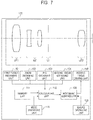
- FIG. 7 is a configuration diagram of a main portion of a zoom lens relating to a fifth embodiment of the present invention.
- the zoom lens in the fifth embodiment includes a second focus obtaining unit 104 configured to obtain a position of a second focus part UF2 and a mode switching unit 115 configured to enable switching among different kinds of adjustment modes of the focus adjustment for the change in each of the optical parameters.
- the zoom lens in the fifth embodiment includes a switching apparatus configured to switch among the adjustment modes.
- the second focus movable lens unit is moved so as to satisfy Expression (1) in the first embodiment. That is, the movement amount f2 of the second focus movable lens unit in the macro operation is controlled so as to be a sum of the movement amount "m" to be used by the macro operating unit and the movement amount "p" involved in the focus adjustment for the change in each of the optical parameters.
- the movement of the second focus movable lens unit which is required for correcting the focus deviation caused by the change in each of the optical parameters, is not performed.
- the second focus movable lens unit is moved so as to satisfy Expression (8) in the fourth embodiment, which is described above.
- the first mode which enables a smooth transition at the time of the switching between the normal image pickup and the macro image pickup, is suitable for an image pickup condition that involves frequent switching.
- the second mode which avoids performing a focus adjustment during macro image pickup, is suitable for a case of continuing close-up image pickup, a case of performing bokeh image pickup, and other such case in which the image pickup condition is fixed to some extent.
- the third mode it is possible to maintain the bokeh diameter at a substantially fixed level when out-of-focus image pickup is intentionally performed, which enables the image pickup more suitable for the intention of the photographer.
- each of the embodiments provides a zoom lens and an image pickup apparatus that are capable of appropriately controlling a focus adjustment and macro image pickup, to thereby be able to perform control that does not give the photographer a sense of discomfort.
- FIG. 8 is a flow chart relating to the fifth embodiment. Processing is started from Step 50.
- the calculation unit 110 reads a signal of the mode switching unit 115 for switching among the adjustment modes, and determines the adjustment mode (Step 51 and Step 52).
- Step 53 the processing in the first embodiment from Step 11 to Step 15 illustrated in FIG. 2 is performed.
- Step 54 the processing in the second embodiment from Step 21 to Step 27 illustrated in FIG. 4 is performed (Step 54).
- Step 55 the processing in the fourth embodiment from Step 32 to Step 38 illustrated in FIG. 6 is performed.
- the procedure returns to Step 51 to continue the flow.
- an image pickup apparatus capable of enjoying the effects of the present invention by configuring an image pickup apparatus including a zoom lens in one embodiment of the present invention and a solid-state image pickup element arranged in an image plane of the zoom lens.
- a lens apparatus including: a first lens unit arranged closest to an object side and configured not to move for zooming; a zoom lens unit configured to move for zooming; an aperture stop; and an imaging lens unit arranged closest to an image side.
- the first lens unit includes a first focus lens unit configured to move for focusing.
- the imaging lens unit includes a second focus lens unit configured to move for focusing and to move for macro image pickup.
- the lens apparatus further includes a controller configured to control a position of the second focus lens unit for the macro image pickup based on a state of at least one of the first focus lens unit, the zoom lens unit, and the aperture stop.
Landscapes
- Physics & Mathematics (AREA)
- General Physics & Mathematics (AREA)
- Optics & Photonics (AREA)
- Engineering & Computer Science (AREA)
- Nonlinear Science (AREA)
- General Engineering & Computer Science (AREA)
- Signal Processing (AREA)
- Multimedia (AREA)
- Lens Barrels (AREA)
- Studio Devices (AREA)
- Focusing (AREA)
- Automatic Focus Adjustment (AREA)
- Lenses (AREA)
Applications Claiming Priority (1)
| Application Number | Priority Date | Filing Date | Title |
|---|---|---|---|
| JP2018069505A JP2019179206A (ja) | 2018-03-30 | 2018-03-30 | ズームレンズ及び撮像装置 |
Publications (2)
| Publication Number | Publication Date |
|---|---|
| EP3547002A2 true EP3547002A2 (de) | 2019-10-02 |
| EP3547002A3 EP3547002A3 (de) | 2020-02-26 |
Family
ID=66001123
Family Applications (1)
| Application Number | Title | Priority Date | Filing Date |
|---|---|---|---|
| EP19166057.0A Withdrawn EP3547002A3 (de) | 2018-03-30 | 2019-03-29 | Linsenvorrichtung und bildaufnahmevorrichtung |
Country Status (4)
| Country | Link |
|---|---|
| US (1) | US11029483B2 (de) |
| EP (1) | EP3547002A3 (de) |
| JP (1) | JP2019179206A (de) |
| CN (1) | CN110320650A (de) |
Families Citing this family (4)
| Publication number | Priority date | Publication date | Assignee | Title |
|---|---|---|---|---|
| JP2019215489A (ja) * | 2018-06-14 | 2019-12-19 | オリンパス株式会社 | 撮像装置および焦点調節方法 |
| US11893668B2 (en) | 2021-03-31 | 2024-02-06 | Leica Camera Ag | Imaging system and method for generating a final digital image via applying a profile to image information |
| US12254644B2 (en) | 2021-03-31 | 2025-03-18 | Leica Camera Ag | Imaging system and method |
| US12450699B2 (en) * | 2022-10-27 | 2025-10-21 | Dell Products L.P. | System and method to enhance optical bokeh effect of computing device cameras |
Citations (2)
| Publication number | Priority date | Publication date | Assignee | Title |
|---|---|---|---|---|
| JPS581401A (ja) | 1978-04-13 | 1983-01-06 | 株式会社櫛原 | メツシユ靴の表甲皮を編製する方法 |
| JPH10186209A (ja) | 1996-12-25 | 1998-07-14 | Fuji Photo Optical Co Ltd | レンズの焦点補正方法及び装置 |
Family Cites Families (15)
| Publication number | Priority date | Publication date | Assignee | Title |
|---|---|---|---|---|
| JPS581401B2 (ja) | 1975-03-01 | 1983-01-11 | 富士写真光機株式会社 | テレビジヨンカメラヨウレンズノ マクロサツエイソウチ |
| US6219098B1 (en) * | 1996-09-24 | 2001-04-17 | Fuji Photo Optical Co., Ltd. | TV camera lens with flange back length controller |
| JP2002107608A (ja) * | 2000-09-29 | 2002-04-10 | Fuji Photo Optical Co Ltd | レンズ制御装置 |
| JP2003156672A (ja) * | 2001-11-22 | 2003-05-30 | Canon Inc | 撮像装置 |
| JP5009091B2 (ja) * | 2007-08-23 | 2012-08-22 | 富士フイルム株式会社 | 焦点調節装置及び焦点調節方法 |
| JP5335445B2 (ja) * | 2009-01-06 | 2013-11-06 | キヤノン株式会社 | レンズ制御装置、光学機器およびレンズ制御方法 |
| JP5315562B2 (ja) * | 2009-02-05 | 2013-10-16 | 株式会社タムロン | マクロレンズ |
| JP6251009B2 (ja) | 2013-11-12 | 2017-12-20 | キヤノン株式会社 | ズームレンズ及びそれを有する撮像装置 |
| JP2015094867A (ja) | 2013-11-12 | 2015-05-18 | キヤノン株式会社 | ズームレンズ及びそれを有する撮像装置 |
| JP6347590B2 (ja) | 2013-11-12 | 2018-06-27 | キヤノン株式会社 | ズームレンズ及びそれを有する撮像装置 |
| JP6529215B2 (ja) | 2013-11-12 | 2019-06-12 | キヤノン株式会社 | ズームレンズ及びそれを有する撮像装置 |
| JP6564208B2 (ja) * | 2015-03-13 | 2019-08-21 | キヤノン株式会社 | ズームレンズ及びそれを有する撮像装置 |
| US9904043B2 (en) | 2015-10-20 | 2018-02-27 | Canon Kabushiki Kaisha | Zoom lens and image pickup apparatus including the same |
| EP3159726B1 (de) | 2015-10-20 | 2024-07-03 | Canon Kabushiki Kaisha | Zoomobjektiv und bildaufnahmevorrichtung damit |
| JP2017167417A (ja) | 2016-03-17 | 2017-09-21 | キヤノン株式会社 | ズームレンズ及びそれを有する撮像装置 |
-
2018
- 2018-03-30 JP JP2018069505A patent/JP2019179206A/ja active Pending
-
2019
- 2019-03-25 US US16/363,478 patent/US11029483B2/en not_active Expired - Fee Related
- 2019-03-28 CN CN201910243894.XA patent/CN110320650A/zh active Pending
- 2019-03-29 EP EP19166057.0A patent/EP3547002A3/de not_active Withdrawn
Patent Citations (2)
| Publication number | Priority date | Publication date | Assignee | Title |
|---|---|---|---|---|
| JPS581401A (ja) | 1978-04-13 | 1983-01-06 | 株式会社櫛原 | メツシユ靴の表甲皮を編製する方法 |
| JPH10186209A (ja) | 1996-12-25 | 1998-07-14 | Fuji Photo Optical Co Ltd | レンズの焦点補正方法及び装置 |
Also Published As
| Publication number | Publication date |
|---|---|
| EP3547002A3 (de) | 2020-02-26 |
| CN110320650A (zh) | 2019-10-11 |
| JP2019179206A (ja) | 2019-10-17 |
| US11029483B2 (en) | 2021-06-08 |
| US20190302399A1 (en) | 2019-10-03 |
Similar Documents
| Publication | Publication Date | Title |
|---|---|---|
| US9432567B2 (en) | Image pickup apparatus and imaging method that perform focus action following zoom action | |
| US11029483B2 (en) | Lens apparatus and image pickup apparatus | |
| JP2008203294A (ja) | 撮像装置 | |
| US8135269B2 (en) | Image pickup apparatus | |
| US7830422B2 (en) | Lens apparatus, image-pickup apparatus, and image-pickup system | |
| US9420165B2 (en) | Focus adjustment apparatus, camera system, and focus adjustment method | |
| JP2004177919A (ja) | ズームレンズの制御装置および撮影システム | |
| JP5173210B2 (ja) | フォーカスレンズ、ズームレンズの駆動手段を有する光学機器 | |
| JP5178186B2 (ja) | レンズ位置制御装置、およびその制御方法 | |
| US8154624B2 (en) | Image pickup apparatus and control method thereof | |
| US8488226B2 (en) | Optical apparatus | |
| JP7130412B2 (ja) | 制御装置、光学機器、撮像装置および制御方法 | |
| JP6639117B2 (ja) | 光学機器およびフォーカス制御プログラム | |
| US20260010057A1 (en) | Optical apparatus attachable to image pickup apparatus and image pickup apparatus attachable to the optical apparatus | |
| JP2004219581A (ja) | 自動焦点調節装置 | |
| JP4810452B2 (ja) | 撮像装置及びその制御方法 | |
| JP2007199195A (ja) | レンズ制御装置 | |
| JP7631160B2 (ja) | 制御装置、レンズ装置、制御方法、及びプログラム | |
| US7447426B2 (en) | Optical apparatus and lens control method | |
| US20050094023A1 (en) | Camera system and lens apparatus | |
| US20110188129A1 (en) | Lens control device having lens position control function for bringing, method of controlling the same, and storage medium | |
| JP2006084640A (ja) | ズームレンズの駆動制御装置 | |
| JP5223353B2 (ja) | カメラ | |
| JP2007298708A (ja) | ズームレンズ制御装置、ズームレンズ制御方法、およびズームレンズ制御プログラム | |
| JP2005099084A (ja) | カメラシステム |
Legal Events
| Date | Code | Title | Description |
|---|---|---|---|
| PUAI | Public reference made under article 153(3) epc to a published international application that has entered the european phase |
Free format text: ORIGINAL CODE: 0009012 |
|
| STAA | Information on the status of an ep patent application or granted ep patent |
Free format text: STATUS: THE APPLICATION HAS BEEN PUBLISHED |
|
| AK | Designated contracting states |
Kind code of ref document: A2 Designated state(s): AL AT BE BG CH CY CZ DE DK EE ES FI FR GB GR HR HU IE IS IT LI LT LU LV MC MK MT NL NO PL PT RO RS SE SI SK SM TR |
|
| PUAL | Search report despatched |
Free format text: ORIGINAL CODE: 0009013 |
|
| AK | Designated contracting states |
Kind code of ref document: A3 Designated state(s): AL AT BE BG CH CY CZ DE DK EE ES FI FR GB GR HR HU IE IS IT LI LT LU LV MC MK MT NL NO PL PT RO RS SE SI SK SM TR |
|
| RIC1 | Information provided on ipc code assigned before grant |
Ipc: G02B 27/64 20060101ALI20200121BHEP Ipc: G02B 15/16 20060101ALI20200121BHEP Ipc: G02B 7/10 20060101AFI20200121BHEP |
|
| STAA | Information on the status of an ep patent application or granted ep patent |
Free format text: STATUS: REQUEST FOR EXAMINATION WAS MADE |
|
| 17P | Request for examination filed |
Effective date: 20200826 |
|
| RBV | Designated contracting states (corrected) |
Designated state(s): AL AT BE BG CH CY CZ DE DK EE ES FI FR GB GR HR HU IE IS IT LI LT LU LV MC MK MT NL NO PL PT RO RS SE SI SK SM TR |
|
| STAA | Information on the status of an ep patent application or granted ep patent |
Free format text: STATUS: EXAMINATION IS IN PROGRESS |
|
| 17Q | First examination report despatched |
Effective date: 20210730 |
|
| STAA | Information on the status of an ep patent application or granted ep patent |
Free format text: STATUS: THE APPLICATION HAS BEEN WITHDRAWN |
|
| 18W | Application withdrawn |
Effective date: 20210917 |