EP3546957A1 - Isolated grounding effectiveness monitor - Google Patents
Isolated grounding effectiveness monitor Download PDFInfo
- Publication number
- EP3546957A1 EP3546957A1 EP18164703.3A EP18164703A EP3546957A1 EP 3546957 A1 EP3546957 A1 EP 3546957A1 EP 18164703 A EP18164703 A EP 18164703A EP 3546957 A1 EP3546957 A1 EP 3546957A1
- Authority
- EP
- European Patent Office
- Prior art keywords
- electrical signal
- devices
- microprocessor
- isolation barrier
- deviations
- Prior art date
- Legal status (The legal status is an assumption and is not a legal conclusion. Google has not performed a legal analysis and makes no representation as to the accuracy of the status listed.)
- Withdrawn
Links
Images




Classifications
-
- G—PHYSICS
- G01—MEASURING; TESTING
- G01R—MEASURING ELECTRIC VARIABLES; MEASURING MAGNETIC VARIABLES
- G01R27/00—Arrangements for measuring resistance, reactance, impedance, or electric characteristics derived therefrom
- G01R27/02—Measuring real or complex resistance, reactance, impedance, or other two-pole characteristics derived therefrom, e.g. time constant
- G01R27/025—Measuring very high resistances, e.g. isolation resistances, i.e. megohm-meters
-
- G—PHYSICS
- G01—MEASURING; TESTING
- G01R—MEASURING ELECTRIC VARIABLES; MEASURING MAGNETIC VARIABLES
- G01R27/00—Arrangements for measuring resistance, reactance, impedance, or electric characteristics derived therefrom
- G01R27/02—Measuring real or complex resistance, reactance, impedance, or other two-pole characteristics derived therefrom, e.g. time constant
- G01R27/14—Measuring resistance by measuring current or voltage obtained from a reference source
-
- G—PHYSICS
- G01—MEASURING; TESTING
- G01R—MEASURING ELECTRIC VARIABLES; MEASURING MAGNETIC VARIABLES
- G01R31/00—Arrangements for testing electric properties; Arrangements for locating electric faults; Arrangements for electrical testing characterised by what is being tested not provided for elsewhere
- G01R31/50—Testing of electric apparatus, lines, cables or components for short-circuits, continuity, leakage current or incorrect line connections
-
- G—PHYSICS
- G01—MEASURING; TESTING
- G01R—MEASURING ELECTRIC VARIABLES; MEASURING MAGNETIC VARIABLES
- G01R31/00—Arrangements for testing electric properties; Arrangements for locating electric faults; Arrangements for electrical testing characterised by what is being tested not provided for elsewhere
- G01R31/50—Testing of electric apparatus, lines, cables or components for short-circuits, continuity, leakage current or incorrect line connections
- G01R31/52—Testing for short-circuits, leakage current or ground faults
-
- G—PHYSICS
- G08—SIGNALLING
- G08B—SIGNALLING SYSTEMS, e.g. PERSONAL CALLING SYSTEMS; ORDER TELEGRAPHS; ALARM SYSTEMS
- G08B21/00—Alarms responsive to a single specified undesired or abnormal condition and not otherwise provided for
- G08B21/18—Status alarms
- G08B21/182—Level alarms, e.g. alarms responsive to variables exceeding a threshold
-
- H—ELECTRICITY
- H03—ELECTRONIC CIRCUITRY
- H03K—PULSE TECHNIQUE
- H03K17/00—Electronic switching or gating, i.e. not by contact-making and –breaking
- H03K17/94—Electronic switching or gating, i.e. not by contact-making and –breaking characterised by the way in which the control signals are generated
- H03K17/96—Touch switches
- H03K17/962—Capacitive touch switches
-
- H—ELECTRICITY
- H03—ELECTRONIC CIRCUITRY
- H03K—PULSE TECHNIQUE
- H03K3/00—Circuits for generating electric pulses; Monostable, bistable or multistable circuits
- H03K3/80—Generating trains of sinusoidal oscillations
-
- H—ELECTRICITY
- H03—ELECTRONIC CIRCUITRY
- H03K—PULSE TECHNIQUE
- H03K2217/00—Indexing scheme related to electronic switching or gating, i.e. not by contact-making or -breaking covered by H03K17/00
- H03K2217/94—Indexing scheme related to electronic switching or gating, i.e. not by contact-making or -breaking covered by H03K17/00 characterised by the way in which the control signal is generated
- H03K2217/96—Touch switches
- H03K2217/9605—Detection of leakage or discharge current across the touching body to ground
Definitions
- the present invention relates generally to an isolated grounding effectiveness monitor, along with methods, systems, and apparatuses related thereto.
- the disclosed technology may be applied to, for example, in the medical domain to reduce or eliminate the risk of electrical shock in multi-device patient testing systems.
- Patient monitoring devices such as those included in hemodynamic systems, include various electrical components that facilitate the collection of measurement data from a patient.
- any parts that could come in contact with the patient are electrically or mechanically isolated from the mains voltage of the device. Electrical isolation is typically achieved by creating a floating ground that is not at the same reference potential as the mains voltage.
- the term "floating ground” refers to a ground that is not electrically connected to the earth. In the context of a patient monitoring device, the floating ground blocks potential leakage from flowing to the patient.
- Embodiments of the present invention address and overcome one or more of the above shortcomings and drawbacks, by providing methods, systems, and apparatuses related to an isolated grounding effectiveness monitor.
- a system for monitoring electrical current leakage comprises a frequency injection circuit, one or more devices, and a microprocessor.
- the frequency injection circuit includes an electronic oscillator providing an electrical signal to a first side of an isolation barrier. This electronic oscillator may be, for example, a sine wave oscillator or an oscillator producing a pulsating direct current signal.
- the devices are located on a second side of the isolation barrier.
- the microprocessor samples the electrical signal and identifies deviations in the sampled electrical signal exceeding a predetermined threshold caused by the one or more devices.
- the microprocessor further generates one or more alert messages based on the identified deviations in the electrical signal.
- microprocessor is connected to the frequency injection circuit on the first side of the isolation barrier.
- the microprocessor is connected to at least one of the devices on the second side of the isolation barrier.
- the devices in the aforementioned system may include a capacitive sensor comprising a touch plate and the electrical signal is changed when a grounded person touches the touch plate.
- system further includes a server computer configured to transmit the one or more alert messages to one or more users over a computer network.
- the microprocessor may be further configured to disable mains electricity powering the one or more devices.
- a method for monitoring electrical current leakage includes continuously sampling, by a microprocessor, an electrical signal transmitted across an isolation barrier to a plurality of devices.
- the electrical signal is sampled on a side of the isolation barrier that comprises an electrical oscillator generating the electrical signal.
- the electrical signal is sampled on a side of the isolation barrier that comprises the plurality of devices.
- the microprocessor identifies deviations in the sampled electrical signal exceeding a predetermined threshold caused by the plurality of devices; and executes one or more remedial actions based on the identified deviations in the electrical signal.
- These remedial actions may include, for example, generation of an alert message describing the deviations in the sampled electrical signal. This alert message may be transmitted to users via email and/or presented on a display. Alternatively (or additionally), the remedial actions may include disabling mains electricity powering the plurality of devices.
- a method for monitoring electrical current leakage includes continuously sampling, by a microprocessor, an electrical signal transmitted across an isolation barrier to a capacitive sensor.
- the microprocessor identifies deviations in the sampled electrical signal exceeding a predetermined threshold caused by activation of the capacitive sensor.
- the microprocessor may then execute one or more remedial actions based on the identified deviations in the electrical signal.
- the following disclosure describes the present invention according to several embodiments directed at methods, systems, and apparatuses associated with an isolated grounding effectiveness monitor.
- the techniques described herein are based on the insight that, current testing is effectively stressing the parasitic capacitance to earth ground across the patient isolation barrier.
- this same parasitic capacitance can be monitored in-vivo using a capacitive monitoring circuit at a much lower, and safer, voltage.
- a custom charge injection circuit on one side of the isolation barrier passes a sense signal through the isolation barrier's parasitic capacitance at one or more frequencies of interest.
- the other side of the isolation barrier monitors the sense signal for threshold detection, changes to the barrier, or the presence of dangerous circumstances. If the isolation barrier's capacitance exceeded a calculated threshold, the sense circuit takes one or more appropriate actions to protect the patient and/or warn the operator.
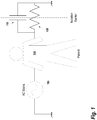
- FIG. 1 outlines the general problem that the techniques seek to address.
- Patient safety is provided by heavy resistance between mains and ground.
- the capacitance between the Patient 110 and ground is equally as important.
- the current through the Patient 110 is proportional to the resistor-capacitor circuit (formed by Resistor 120 and Capacitor 115), as well as the frequency of the voltage source (i.e., AC Mains 105).
- the current density and specific pathway causes injury to the patient.
- X c 1 2 ⁇ fC
- I RMS V RMS X C
- the capacitance may be measured as people and equipment are connected to the medical device being monitored.
- actively testing capacitance offers additional benefits not present in current testing procedures. For example, there are many pieces of equipment attached to an individual during patient monitoring. Each piece of equipment can be made by different manufacturers. Each manufacturer tests their own equipment; however, the interconnections between equipment from different manufactures go untested. However, by actively testing whether the isolation barrier's capacitance exceeded a calculated threshold, the overall system can be robust enough to detect faults even as various devices are connected and disconnected, or used in various combinations with one another.
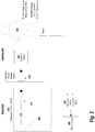
- FIG. 2 provides an overview of a method of monitoring a group of devices for electrical leakage currents using parasitic capacitance, according to some embodiments of the present invention.
- This example is divided by a Capacitor 220 across the patient isolation barrier.
- the Signal On the left side of the Capacitor 220, referred to herein as the “Signal Side,” the signal is generated by Frequency Injection Circuit 245.
- the right side of the Capacitor 220 in FIG. 2 in which the Patient 230 is located, is referred to as the "Isolated Side.”
- Frequency Injection Circuit 245 comprises an Electronic Oscillator 205 that provides a source of repetitive electrical signals at a particular amplitude.
- the source voltage provided by the Electronic Oscillator 205 could be, for example, either an AC frequency monitor for peak-to-peak voltage or a pulsed voltage in which the rise and fall times are monitored.
- the Electronic Oscillator 205 is a sine wave oscillator may produce a sine wave at a certain frequency (e.g., 1 MHz or 10 MHz). The exact frequency can be selected on a design by design basis for maximum sensitivity. Engineering studies can be performed in order to select the optimum frequency.
- the Electronic Oscillator 205 produces a pulsating direct current signal.
- Capacitor 220 is the parasitic capacitance across the patient isolation barrier.
- the Capacitor 220 may be a physical capacitor that is purposely inserted into the patient isolation barrier. Using the Capacitor 220, AC is coupled with the signal and DC is blocked such that only the carrier wave enters the other side of the isolation barrier.
- FIGS. 3A - 3D show various examples of the Capacitive Sensor 225 which can be implemented.
- Capacitive Sensor 225 operates similar to how a conventional touch screen operates.
- FIG. 3A shows an overhead view of the Capacitive Sensor 225 with a touch plate 305 located at the center.
- FIG. 3B there are two ground plates 310A, 310B on opposite sides of the touch plate 305. Each plate is made of a printed circuit board (PCB) connected over copper sections.
- FIG. 3C shows how a human's finger can be used as a conductor.
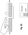
- FIG. 3D shows how the human's finger can be used as dielectric; thus, if the Capacitive Sensor 225 is sensitive enough, an actual touch of the sensor would not be necessary.
- the carrier wave associated with the generated signal is received across the patient isolation barrier and is used as input to the Capacitive Sensor 225.
- the resultant capacitance change will start to affect the signal.
- FIG. 4 illustrates how the rise and fall times of a pulsed source signal (top) can be affected by parasitic capacitance and result in changes to a measured signal (bottom). This rise and fall is proportional to the capacitance added to the Capacitive Sensor 225. This can be understood as essentially adding capacitors in parallel. If a sinusoidal signal is used (e.g., 1 MHz, 10 MHz), the entire AC signal passes over the patient isolation barrier and, as capacitance is added at the Capacitive Sensor 225, the resulting waveform will shrink.
- a sinusoidal signal e.g., 1 MHz, 10 MHz
- An Analog to Digital Converter (ADC) 235 on the Signal Side converts the signal generated at the Capacitive Sensor 225 to digital and provides the converted signal to the Microprocessor 240.
- the Microprocessor 240 measures parasitic capacitance based on the received signal and calculates the potential for deadly leakage currents.
- the Microprocessor 240 actively monitors the signal for deviations into order to identify one or more alert conditions. For example, the Microprocessor 240 may indicate that the Patient 230 (or other individual) touched something he or she should not have touched. Alternatively, the Microprocessor 240 may identify one or more pieces of equipment that were incorrectly connected, or were connected in a manner that overly degrades system performance.
- a predetermined threshold is set to such that deviations exceeding the threshold trigger the Microprocessor 240 to execute one or more remedial actions (see FIG. 5 ).
- This threshold may be set based, for example, on the known characteristics of the electrical signal generated by the Frequency Injection Circuit 245 and the anticipated configuration of the system (e.g., the number of devices to be connected to the system and their respective characteristics). It should be noted that sampling of the signal can be performed on either side of the patient isolation barrier. Thus, in other embodiments, the ADC 235 and Microprocessor 240 may be located on the Isolated Side of the patient isolation barrier.
- the various components shown on the Signal Side of FIG. 2 can, in general, be integrated with any electrical device.
- the components can be embodied into a specialized device that connects one or more medical devices.
- the components can be used in a custom ground fault circuit interrupter (GFCI). If a person touches the jacket of cable, the Microprocessor 240 in the GFCI could smartly turn off mains before any potential hazard occurs.
- GFCI ground fault circuit interrupter
- FIG. 2 shows how the components may react to capacitance changes that result from the Patient 230 touching the Capacitive Sensor 225, in general any changes in capacitance may trigger the various alert mechanisms of the Microprocessor 240. For example, if one or more devices are connected that cause a significant capacitance change, the alert mechanisms can be similarly triggered.
- FIG. 5 illustrates an example of the remedial actions that can be performed when the Frequency Injection Circuit 245 detects deviations in the sense signal transmitted across the isolation barrier.
- two actions are performed.
- the alert message is transmitted to a Server Computer 505 that formats the alert into an email message that, in turn, is transmitted over a Network 510 to one or more Users 515.
- the alert message may be transmitted between the Frequency Injection Circuit 245 and the Server Computer 505 using any format generally known in the art.
- the alert message is transmitted in Extensible Markup Language (XML) and the Server Computer 505 includes software that enables it to extract the relevant information from the XML and format it into an email message.
- XML Extensible Markup Language
- the Frequency Injection Circuit 245 transmits instructions for displaying the alert message to a Display 520.
- a different visual mechanism may be used (e.g., flashing light).
- Other, non-visual alert mechanisms may be used as well (e.g., buzzers or other auditory alarms).
- An activity performed automatically is performed in response to one or more executable instructions or device operation without user direct initiation of the activity.
Landscapes
- Physics & Mathematics (AREA)
- General Physics & Mathematics (AREA)
- Business, Economics & Management (AREA)
- Emergency Management (AREA)
- Measuring And Recording Apparatus For Diagnosis (AREA)
- Measurement Of Resistance Or Impedance (AREA)
Abstract
Description
- The present invention relates generally to an isolated grounding effectiveness monitor, along with methods, systems, and apparatuses related thereto. The disclosed technology may be applied to, for example, in the medical domain to reduce or eliminate the risk of electrical shock in multi-device patient testing systems.
- Patient monitoring devices, such as those included in hemodynamic systems, include various electrical components that facilitate the collection of measurement data from a patient. In order to protect the patient from electrical shock, any parts that could come in contact with the patient are electrically or mechanically isolated from the mains voltage of the device. Electrical isolation is typically achieved by creating a floating ground that is not at the same reference potential as the mains voltage. As would be understood in the art, the term "floating ground" refers to a ground that is not electrically connected to the earth. In the context of a patient monitoring device, the floating ground blocks potential leakage from flowing to the patient.
- Failure of the isolation barrier provided by a floating ground can result in electrical shock to the patient or partial failure of this barrier can result in compromised signal quality. Thus, prior to implementation, manufacturers of medical devices typically test every device manufactured for electrical leakage currents using specialized leakage test equipment. This equipment applies a mains potential on the patient applied part and looks for a breakdown of the isolation barrier. This testing process is expensive, time consuming, necessitates specialized equipment, and requires a trained operator to execute the test procedure. Moreover, it is not uncommon for multiple patient connections to be connected to the same floating ground. This can lead to uncertainty of the parasitic capacitance to earth ground. When two different manufacturers connect equipment together, they are only tested individually rather than together.
- Embodiments of the present invention address and overcome one or more of the above shortcomings and drawbacks, by providing methods, systems, and apparatuses related to an isolated grounding effectiveness monitor.
- According to some embodiments, a system for monitoring electrical current leakage comprises a frequency injection circuit, one or more devices, and a microprocessor. The frequency injection circuit includes an electronic oscillator providing an electrical signal to a first side of an isolation barrier. This electronic oscillator may be, for example, a sine wave oscillator or an oscillator producing a pulsating direct current signal. The devices are located on a second side of the isolation barrier. The microprocessor samples the electrical signal and identifies deviations in the sampled electrical signal exceeding a predetermined threshold caused by the one or more devices. The microprocessor further generates one or more alert messages based on the identified deviations in the electrical signal.
- Various enhancements, refinements, and other modifications may be made to the aforementioned system in different embodiments of the present invention. For example, in some embodiments, microprocessor is connected to the frequency injection circuit on the first side of the isolation barrier. In other embodiments, the microprocessor is connected to at least one of the devices on the second side of the isolation barrier. The devices in the aforementioned system may include a capacitive sensor comprising a touch plate and the electrical signal is changed when a grounded person touches the touch plate.
- In some embodiments of the aforementioned system, the system further includes a server computer configured to transmit the one or more alert messages to one or more users over a computer network. Additionally, the microprocessor may be further configured to disable mains electricity powering the one or more devices.
- According to other embodiments, a method for monitoring electrical current leakage includes continuously sampling, by a microprocessor, an electrical signal transmitted across an isolation barrier to a plurality of devices. In some embodiments, the electrical signal is sampled on a side of the isolation barrier that comprises an electrical oscillator generating the electrical signal. In other embodiments, the electrical signal is sampled on a side of the isolation barrier that comprises the plurality of devices. The microprocessor identifies deviations in the sampled electrical signal exceeding a predetermined threshold caused by the plurality of devices; and executes one or more remedial actions based on the identified deviations in the electrical signal. These remedial actions may include, for example, generation of an alert message describing the deviations in the sampled electrical signal. This alert message may be transmitted to users via email and/or presented on a display. Alternatively (or additionally), the remedial actions may include disabling mains electricity powering the plurality of devices.
- According to other embodiments, a method for monitoring electrical current leakage includes continuously sampling, by a microprocessor, an electrical signal transmitted across an isolation barrier to a capacitive sensor. The microprocessor identifies deviations in the sampled electrical signal exceeding a predetermined threshold caused by activation of the capacitive sensor. The microprocessor may then execute one or more remedial actions based on the identified deviations in the electrical signal.
- Additional features and advantages of the invention will be made apparent from the following detailed description of illustrative embodiments that proceeds with reference to the accompanying drawings.
- The foregoing and other aspects of the present invention are best understood from the following detailed description when read in connection with the accompanying drawings. For the purpose of illustrating the invention, there are shown in the drawings embodiments that are presently preferred, it being understood, however, that the invention is not limited to the specific instrumentalities disclosed. Included in the drawings are the following Figures:
-
FIG. 1 illustrates an example of how electrical leakage can occur; -
FIG. 2 provides an overview of a method of monitoring a group of devices for electrical leakage currents using parasitic capacitance, according to some embodiments of the present invention; -
FIG. 3A provides an overview of a Capacitive Sensor, according to some embodiments; -
FIG. 3B provides an alternative view of the Capacitive Sensor, according to some embodiments; -
FIG. 3C shows how the Capacitive Sensor can be implemented with a human's finger used as a conductor, according to some embodiments; -
FIG. 3D shows how the Capacitive Sensor can be implemented with a human's finger used as dielectric, according to some embodiments; -
FIG. 4 shows an example of how the rise and fall times of a pulsed source signal (top) can be affected by parasitic capacitance and result in changes to a measured signal (bottom); and -
FIG. 5 illustrates an example of the remedial actions that can be performed when a Frequency Injection Circuit detects deviations in the sense signal transmitted across the isolation barrier. - The following disclosure describes the present invention according to several embodiments directed at methods, systems, and apparatuses associated with an isolated grounding effectiveness monitor. The techniques described herein are based on the insight that, current testing is effectively stressing the parasitic capacitance to earth ground across the patient isolation barrier. As described in further detail below, this same parasitic capacitance can be monitored in-vivo using a capacitive monitoring circuit at a much lower, and safer, voltage. Briefly, a custom charge injection circuit on one side of the isolation barrier passes a sense signal through the isolation barrier's parasitic capacitance at one or more frequencies of interest. The other side of the isolation barrier monitors the sense signal for threshold detection, changes to the barrier, or the presence of dangerous circumstances. If the isolation barrier's capacitance exceeded a calculated threshold, the sense circuit takes one or more appropriate actions to protect the patient and/or warn the operator.
-
FIG. 1 outlines the general problem that the techniques seek to address. Patient safety is provided by heavy resistance between mains and ground. However, the capacitance between thePatient 110 and ground is equally as important. The current through thePatient 110 is proportional to the resistor-capacitor circuit (formed byResistor 120 and Capacitor 115), as well as the frequency of the voltage source (i.e., AC Mains 105). The current density and specific pathway causes injury to the patient. - As is well understood in the art, for an alternating current (AC) circuit, the current across the capacitor may be determined by the following equations:


-
FIG. 2 provides an overview of a method of monitoring a group of devices for electrical leakage currents using parasitic capacitance, according to some embodiments of the present invention. This example is divided by aCapacitor 220 across the patient isolation barrier. On the left side of theCapacitor 220, referred to herein as the "Signal Side," the signal is generated byFrequency Injection Circuit 245. The right side of theCapacitor 220 inFIG. 2 , in which thePatient 230 is located, is referred to as the "Isolated Side." -
Frequency Injection Circuit 245 comprises anElectronic Oscillator 205 that provides a source of repetitive electrical signals at a particular amplitude. The source voltage provided by theElectronic Oscillator 205 could be, for example, either an AC frequency monitor for peak-to-peak voltage or a pulsed voltage in which the rise and fall times are monitored. For example, in one embodiment, theElectronic Oscillator 205 is a sine wave oscillator may produce a sine wave at a certain frequency (e.g., 1 MHz or 10 MHz). The exact frequency can be selected on a design by design basis for maximum sensitivity. Engineering studies can be performed in order to select the optimum frequency. In other embodiments, theElectronic Oscillator 205 produces a pulsating direct current signal. The signal generated by theElectronic Oscillator 205 passes through aBuffer 210 andResistor 215 before being used as an input to theCapacitor 220 across the patient isolation barrier. In the example ofFIG. 2 ,Capacitor 220 is the parasitic capacitance across the patient isolation barrier. Alternatively, in other embodiments, theCapacitor 220 may be a physical capacitor that is purposely inserted into the patient isolation barrier. Using theCapacitor 220, AC is coupled with the signal and DC is blocked such that only the carrier wave enters the other side of the isolation barrier. -
FIGS. 3A - 3D show various examples of theCapacitive Sensor 225 which can be implemented. For example, in some embodiments,Capacitive Sensor 225 operates similar to how a conventional touch screen operates.FIG. 3A shows an overhead view of theCapacitive Sensor 225 with atouch plate 305 located at the center. As shown inFIG. 3B , there are twoground plates touch plate 305. Each plate is made of a printed circuit board (PCB) connected over copper sections. Using this configuration,FIG. 3C shows how a human's finger can be used as a conductor.FIG. 3D shows how the human's finger can be used as dielectric; thus, if theCapacitive Sensor 225 is sensitive enough, an actual touch of the sensor would not be necessary. - Returning to
FIG. 2 , the carrier wave associated with the generated signal is received across the patient isolation barrier and is used as input to theCapacitive Sensor 225. Once thePatient 230 touches theCapacitive Sensor 225, the resultant capacitance change will start to affect the signal. For example,FIG. 4 illustrates how the rise and fall times of a pulsed source signal (top) can be affected by parasitic capacitance and result in changes to a measured signal (bottom). This rise and fall is proportional to the capacitance added to theCapacitive Sensor 225. This can be understood as essentially adding capacitors in parallel. If a sinusoidal signal is used (e.g., 1 MHz, 10 MHz), the entire AC signal passes over the patient isolation barrier and, as capacitance is added at theCapacitive Sensor 225, the resulting waveform will shrink. - An Analog to Digital Converter (ADC) 235 on the Signal Side converts the signal generated at the
Capacitive Sensor 225 to digital and provides the converted signal to theMicroprocessor 240. TheMicroprocessor 240 measures parasitic capacitance based on the received signal and calculates the potential for deadly leakage currents. In some embodiments, theMicroprocessor 240 actively monitors the signal for deviations into order to identify one or more alert conditions. For example, theMicroprocessor 240 may indicate that the Patient 230 (or other individual) touched something he or she should not have touched. Alternatively, theMicroprocessor 240 may identify one or more pieces of equipment that were incorrectly connected, or were connected in a manner that overly degrades system performance. In some embodiments, a predetermined threshold is set to such that deviations exceeding the threshold trigger theMicroprocessor 240 to execute one or more remedial actions (seeFIG. 5 ). This threshold may be set based, for example, on the known characteristics of the electrical signal generated by theFrequency Injection Circuit 245 and the anticipated configuration of the system (e.g., the number of devices to be connected to the system and their respective characteristics). It should be noted that sampling of the signal can be performed on either side of the patient isolation barrier. Thus, in other embodiments, theADC 235 andMicroprocessor 240 may be located on the Isolated Side of the patient isolation barrier. - The various components shown on the Signal Side of
FIG. 2 can, in general, be integrated with any electrical device. Thus, within the medical diagnostics domain, the components can be embodied into a specialized device that connects one or more medical devices. For example, the components can be used in a custom ground fault circuit interrupter (GFCI). If a person touches the jacket of cable, theMicroprocessor 240 in the GFCI could smartly turn off mains before any potential hazard occurs. Alternatively, the components shown on the Signal Side ofFIG. 2 can be integrated into one or more medical devices. Moreover, althoughFIG. 2 shows how the components may react to capacitance changes that result from thePatient 230 touching theCapacitive Sensor 225, in general any changes in capacitance may trigger the various alert mechanisms of theMicroprocessor 240. For example, if one or more devices are connected that cause a significant capacitance change, the alert mechanisms can be similarly triggered. -
FIG. 5 illustrates an example of the remedial actions that can be performed when theFrequency Injection Circuit 245 detects deviations in the sense signal transmitted across the isolation barrier. In this example, two actions are performed. First, the alert message is transmitted to aServer Computer 505 that formats the alert into an email message that, in turn, is transmitted over aNetwork 510 to one ormore Users 515. The alert message may be transmitted between theFrequency Injection Circuit 245 and theServer Computer 505 using any format generally known in the art. For example, in one embodiment, the alert message is transmitted in Extensible Markup Language (XML) and theServer Computer 505 includes software that enables it to extract the relevant information from the XML and format it into an email message. As a second example, theFrequency Injection Circuit 245 transmits instructions for displaying the alert message to aDisplay 520. As an alternative to displaying the alert message on a computer monitor, in some embodiments, a different visual mechanism may be used (e.g., flashing light). Other, non-visual alert mechanisms may be used as well (e.g., buzzers or other auditory alarms). - It should also be noted that the systems and techniques described herein are not limited to the medical domain. Rather, the principles can generally be applied in any environment where electrical devices are separated from humans (or other systems) by an isolation barrier.
- The functions and process steps herein may be performed automatically, wholly or partially in response to user command. An activity (including a step) performed automatically is performed in response to one or more executable instructions or device operation without user direct initiation of the activity.
- The system and processes of the figures are not exclusive. Other systems, processes and menus may be derived in accordance with the principles of the invention to accomplish the same objectives. Although this invention has been described with reference to particular embodiments, it is to be understood that the embodiments and variations shown and described herein are for illustration purposes only. Modifications to the current design may be implemented by those skilled in the art, without departing from the scope of the invention. As described herein, the various systems, subsystems, agents, managers and processes can be implemented using hardware components, software components, and/or combinations thereof. No claim element herein is to be construed under the provisions of 35 U.S.C. 112(f), unless the element is expressly recited using the phrase "means for."
Claims (15)
- A system for monitoring electrical current leakage, the system comprises:a frequency injection circuit (245) comprising an electronic oscillator (205) providing an electrical signal to a first side of an isolation barrier;one or more devices located on a second side of the isolation barrier;a microprocessor (240) configured to:sample the electrical signal,identify deviations in the sampled electrical signal exceeding a predetermined threshold caused by the one or more devices, andgenerate one or more alert messages based on the identified deviations in the electrical signal.
- The system according to claim 1, wherein the electronic oscillator (205) is a sine wave oscillator.
- The system according to claim 1 or 2, wherein the electronic oscillator (205) produces a pulsating direct current signal.
- The system according to any of the preceding claims, wherein the microprocessor (240) is connected to the frequency injection circuit (245) on the first side of the isolation barrier.
- The system according to any of the preceding claims, wherein the microprocessor (240) is connected to at least one of the devices on the second side of the isolation barrier.
- The system according to any of the preceding claims, wherein the one or more devices comprise a capacitive sensor (225) comprising a touch plate (305) and the electrical signal is changed when a grounded person touches the touch plate (305).
- The system according to any of the preceding claims, further comprising:a server computer (505) configured to transmit the one or more alert messages to one or more users (515) over a computer network (510).
- The system according to any of the preceding claims, wherein the microprocessor (240) is further configured to:disable mains electricity powering the one or more devices.
- A method for monitoring electrical current leakage, the method comprises:continuously sampling, by a microprocessor (240), an electrical signal transmitted across an isolation barrier to a plurality of devices or to a capacitive sensor (225);identifying, by the microprocessor (240), deviations in the sampled electrical signal exceeding a predetermined threshold caused by the plurality of devices or caused by activation of the capacitive sensor (225); andexecuting, by the microprocessor (240), one or more remedial actions based on the identified deviations in the electrical signal.
- The method according to claim 9, wherein the electrical signal is sampled on a side of the isolation barrier that comprises an electrical oscillator generating the electrical signal.
- The method according to claims 9 or 10, wherein the electrical signal is sampled on a side of the isolation barrier that comprises the plurality of devices.
- The method according to any of the preceding claims 9 to 11, wherein the one or more remedial actions comprise generation of an alert message describing the deviations in the sampled electrical signal.
- The method according to claim 12, further comprising:transmitting an email with the alert message to one or more users.
- The method according to claims 12 or 13, further comprising:presenting the alert message a display.
- The method according to any of the preceding claims 9 to 14, wherein the one or more remedial actions comprise disabling mains electricity powering the plurality of devices.
Priority Applications (3)
| Application Number | Priority Date | Filing Date | Title |
|---|---|---|---|
| EP18164703.3A EP3546957A1 (en) | 2018-03-28 | 2018-03-28 | Isolated grounding effectiveness monitor |
| US16/275,879 US10725120B2 (en) | 2018-03-28 | 2019-02-14 | Isolated grounding effectiveness monitor |
| CN201910242757.4A CN110320431A (en) | 2018-03-28 | 2019-03-28 | Earthing effect monitor is isolated |
Applications Claiming Priority (1)
| Application Number | Priority Date | Filing Date | Title |
|---|---|---|---|
| EP18164703.3A EP3546957A1 (en) | 2018-03-28 | 2018-03-28 | Isolated grounding effectiveness monitor |
Publications (1)
| Publication Number | Publication Date |
|---|---|
| EP3546957A1 true EP3546957A1 (en) | 2019-10-02 |
Family
ID=61972290
Family Applications (1)
| Application Number | Title | Priority Date | Filing Date |
|---|---|---|---|
| EP18164703.3A Withdrawn EP3546957A1 (en) | 2018-03-28 | 2018-03-28 | Isolated grounding effectiveness monitor |
Country Status (3)
| Country | Link |
|---|---|
| US (1) | US10725120B2 (en) |
| EP (1) | EP3546957A1 (en) |
| CN (1) | CN110320431A (en) |
Citations (12)
| Publication number | Priority date | Publication date | Assignee | Title |
|---|---|---|---|---|
| US4200104A (en) * | 1977-11-17 | 1980-04-29 | Valleylab, Inc. | Contact area measurement apparatus for use in electrosurgery |
| GB2146534A (en) * | 1983-09-13 | 1985-04-24 | Matburn | Electrosurgical system |
| US5101160A (en) * | 1989-05-19 | 1992-03-31 | Merlin Gerin | Digital isolation monitor for an electrical power system |
| EP0654673A1 (en) * | 1993-11-24 | 1995-05-24 | Dipl.-Ing. Walther Bender GmbH & Co. KG | Method and apparatus for insulation monitoring in unearthed DC and AC networks |
| DE10106200C1 (en) * | 2001-02-10 | 2002-09-05 | Ean Elektroschaltanlagen Gmbh | Method and device for monitoring the insulation of ungrounded electrical networks |
| WO2005006000A1 (en) * | 2003-07-14 | 2005-01-20 | Jurong Facilities Management Pte Ltd | Electrical switchboard monitoring system |
| US20120146655A1 (en) * | 2010-12-10 | 2012-06-14 | Raritan Americas, Inc. | Methods and apparatus for sensing ground leakage and automated self testing thereof |
| US20120299599A1 (en) * | 2011-05-23 | 2012-11-29 | Omron Automotive Electronics Co., Ltd. | Electric leakage sensing apparatus |
| US20140097854A1 (en) * | 2011-05-24 | 2014-04-10 | Sma Solar Technology Ag | Isolation Monitoring Using a Test Signal of Variable Frequency |
| US20160334452A1 (en) * | 2013-12-04 | 2016-11-17 | Renault S.A.S. | Estimation of the insulation resistance between a motor vehicle battery and the earth |
| US20170110869A1 (en) * | 2014-01-08 | 2017-04-20 | Electricite De France | Electrical measuring device for measuring the resistance of an earth connection of an electrical facility |
| US20170146584A1 (en) * | 2000-12-28 | 2017-05-25 | Senorx, Inc. | Electrosurgical medical system and method |
Family Cites Families (14)
| Publication number | Priority date | Publication date | Assignee | Title |
|---|---|---|---|---|
| US5616091A (en) | 1991-10-10 | 1997-04-01 | Warren; Walter S. | Integrated hydro-mechanical multiple lockup transmission |
| US5650750A (en) | 1995-03-03 | 1997-07-22 | Heartstream, Inc. | Common mode signal and circuit fault detection in differential signal detectors |
| JPH09219277A (en) * | 1996-02-08 | 1997-08-19 | Mitsubishi Electric Corp | Lightning arrester monitoring device for thyristor valve |
| US8660500B2 (en) * | 2009-06-09 | 2014-02-25 | Broadcom Corporation | Method and system for a voltage-controlled oscillator with a leaky wave antenna |
| TWI475451B (en) * | 2011-01-07 | 2015-03-01 | Egalax Empia Technology Inc | Capacitive sensor and detection method using the same |
| JP6039091B2 (en) | 2012-10-12 | 2016-12-07 | カーディオインサイト テクノロジーズ インコーポレイテッド | Medical amplifier isolation |
| CN103412172A (en) * | 2013-07-16 | 2013-11-27 | 国家电网公司 | Multi-channel leakage current measurement system and measurement method |
| CN103545786B (en) * | 2013-10-18 | 2016-02-03 | 乐金电子研发中心(上海)有限公司 | A kind of protective device of leakage current |
| JP6306913B2 (en) * | 2014-03-19 | 2018-04-04 | 株式会社小松製作所 | In-vehicle power supply system leakage detector and hydraulic excavator |
| US9680528B2 (en) | 2014-10-28 | 2017-06-13 | Nxp B.V. | Communication between capacitive-isolated devices |
| EP4445861A3 (en) * | 2015-09-30 | 2025-01-08 | Ethicon LLC | Apparatus for selecting operations of a surgical instrument based on user intention |
| US20170086909A1 (en) * | 2015-09-30 | 2017-03-30 | Ethicon Endo-Surgery, Llc | Frequency agile generator for a surgical instrument |
| US10322291B2 (en) * | 2015-12-04 | 2019-06-18 | West Affum Holdings Corp. | Wearable cardioverter defibrillator (WCD) system with isolated patient parameter component |
| US10278256B2 (en) * | 2016-11-18 | 2019-04-30 | Wei-Jing Tseng | LED tube adapted for use with electronic ballast |
-
2018
- 2018-03-28 EP EP18164703.3A patent/EP3546957A1/en not_active Withdrawn
-
2019
- 2019-02-14 US US16/275,879 patent/US10725120B2/en active Active
- 2019-03-28 CN CN201910242757.4A patent/CN110320431A/en active Pending
Patent Citations (12)
| Publication number | Priority date | Publication date | Assignee | Title |
|---|---|---|---|---|
| US4200104A (en) * | 1977-11-17 | 1980-04-29 | Valleylab, Inc. | Contact area measurement apparatus for use in electrosurgery |
| GB2146534A (en) * | 1983-09-13 | 1985-04-24 | Matburn | Electrosurgical system |
| US5101160A (en) * | 1989-05-19 | 1992-03-31 | Merlin Gerin | Digital isolation monitor for an electrical power system |
| EP0654673A1 (en) * | 1993-11-24 | 1995-05-24 | Dipl.-Ing. Walther Bender GmbH & Co. KG | Method and apparatus for insulation monitoring in unearthed DC and AC networks |
| US20170146584A1 (en) * | 2000-12-28 | 2017-05-25 | Senorx, Inc. | Electrosurgical medical system and method |
| DE10106200C1 (en) * | 2001-02-10 | 2002-09-05 | Ean Elektroschaltanlagen Gmbh | Method and device for monitoring the insulation of ungrounded electrical networks |
| WO2005006000A1 (en) * | 2003-07-14 | 2005-01-20 | Jurong Facilities Management Pte Ltd | Electrical switchboard monitoring system |
| US20120146655A1 (en) * | 2010-12-10 | 2012-06-14 | Raritan Americas, Inc. | Methods and apparatus for sensing ground leakage and automated self testing thereof |
| US20120299599A1 (en) * | 2011-05-23 | 2012-11-29 | Omron Automotive Electronics Co., Ltd. | Electric leakage sensing apparatus |
| US20140097854A1 (en) * | 2011-05-24 | 2014-04-10 | Sma Solar Technology Ag | Isolation Monitoring Using a Test Signal of Variable Frequency |
| US20160334452A1 (en) * | 2013-12-04 | 2016-11-17 | Renault S.A.S. | Estimation of the insulation resistance between a motor vehicle battery and the earth |
| US20170110869A1 (en) * | 2014-01-08 | 2017-04-20 | Electricite De France | Electrical measuring device for measuring the resistance of an earth connection of an electrical facility |
Also Published As
| Publication number | Publication date |
|---|---|
| US20190302164A1 (en) | 2019-10-03 |
| US10725120B2 (en) | 2020-07-28 |
| CN110320431A (en) | 2019-10-11 |
Similar Documents
| Publication | Publication Date | Title |
|---|---|---|
| US6287328B1 (en) | Multivariable artifact assessment | |
| CN111700605B (en) | Detecting interference when measuring bioelectrical signals | |
| EP2092357B1 (en) | A cable detection system | |
| JP7242225B2 (en) | Partial discharge detection device, partial discharge detection method, partial discharge detection system, and computer program | |
| KR101070832B1 (en) | Anomaly Detection Method of Switchgear with Self-diagnosis Function | |
| US8749246B2 (en) | Method and device for determining a maximum leakage current | |
| JPS62155841A (en) | Method and apparatus for monitoring neutral electrode for high frequency surgical apparatus | |
| US20100033190A1 (en) | Electrical test device | |
| KR101601605B1 (en) | Smart distribution box for preventing an electrical accident | |
| CN112924837B (en) | Circuit assembly for voltage checking and partial discharge detection | |
| US5650750A (en) | Common mode signal and circuit fault detection in differential signal detectors | |
| JP3628701B2 (en) | Shield integrity monitor | |
| CN109116131B (en) | Test device, method for testing protection unit and protection unit | |
| CN109596956B (en) | DC series arc detection method and device | |
| JP2013156247A (en) | Determination of location of electrical disturbance | |
| JP4248627B2 (en) | Ground fault inspection device | |
| CN107621596A (en) | Live line work insulating takes surface insulation performance detecting system | |
| JP4751789B2 (en) | Non-grounded circuit insulation monitoring method and apparatus | |
| US10725120B2 (en) | Isolated grounding effectiveness monitor | |
| JP6788259B2 (en) | Loop impedance acquisition method and loop impedance tester | |
| EP3912583B1 (en) | Testing electrode quality | |
| EP4215930B1 (en) | Self-test for electrostatic charge variation sensors | |
| US5119031A (en) | Method and apparatus for monitoring the integrity of a multiple-planes grounding system | |
| EP4377704B1 (en) | Monitoring electrical systems with multiple ground connection points | |
| CN112763839A (en) | Fault arc detection method and device |
Legal Events
| Date | Code | Title | Description |
|---|---|---|---|
| PUAI | Public reference made under article 153(3) epc to a published international application that has entered the european phase |
Free format text: ORIGINAL CODE: 0009012 |
|
| STAA | Information on the status of an ep patent application or granted ep patent |
Free format text: STATUS: REQUEST FOR EXAMINATION WAS MADE |
|
| 17P | Request for examination filed |
Effective date: 20180328 |
|
| AK | Designated contracting states |
Kind code of ref document: A1 Designated state(s): AL AT BE BG CH CY CZ DE DK EE ES FI FR GB GR HR HU IE IS IT LI LT LU LV MC MK MT NL NO PL PT RO RS SE SI SK SM TR |
|
| AX | Request for extension of the european patent |
Extension state: BA ME |
|
| RBV | Designated contracting states (corrected) |
Designated state(s): AL AT BE BG CH CY CZ DE DK EE ES FI FR GB GR HR HU IE IS IT LI LT LU LV MC MK MT NL NO PL PT RO RS SE SI SK SM TR |
|
| STAA | Information on the status of an ep patent application or granted ep patent |
Free format text: STATUS: EXAMINATION IS IN PROGRESS |
|
| 17Q | First examination report despatched |
Effective date: 20210611 |
|
| RAP1 | Party data changed (applicant data changed or rights of an application transferred) |
Owner name: ICE CAP, SERIES 106 OF ALLIED SECURITY TRUST I |
|
| RAP1 | Party data changed (applicant data changed or rights of an application transferred) |
Owner name: PIXART IMAGING INC. |
|
| STAA | Information on the status of an ep patent application or granted ep patent |
Free format text: STATUS: THE APPLICATION IS DEEMED TO BE WITHDRAWN |
|
| 18D | Application deemed to be withdrawn |
Effective date: 20221001 |