EP3546776A1 - Sealing device and hub bearing - Google Patents
Sealing device and hub bearing Download PDFInfo
- Publication number
- EP3546776A1 EP3546776A1 EP17872919.0A EP17872919A EP3546776A1 EP 3546776 A1 EP3546776 A1 EP 3546776A1 EP 17872919 A EP17872919 A EP 17872919A EP 3546776 A1 EP3546776 A1 EP 3546776A1
- Authority
- EP
- European Patent Office
- Prior art keywords
- lip
- grease
- projections
- depressions
- pear
- Prior art date
- Legal status (The legal status is an assumption and is not a legal conclusion. Google has not performed a legal analysis and makes no representation as to the accuracy of the status listed.)
- Granted
Links
Images



Classifications
-
- F—MECHANICAL ENGINEERING; LIGHTING; HEATING; WEAPONS; BLASTING
- F16—ENGINEERING ELEMENTS AND UNITS; GENERAL MEASURES FOR PRODUCING AND MAINTAINING EFFECTIVE FUNCTIONING OF MACHINES OR INSTALLATIONS; THERMAL INSULATION IN GENERAL
- F16C—SHAFTS; FLEXIBLE SHAFTS; ELEMENTS OR CRANKSHAFT MECHANISMS; ROTARY BODIES OTHER THAN GEARING ELEMENTS; BEARINGS
- F16C33/00—Parts of bearings; Special methods for making bearings or parts thereof
- F16C33/72—Sealings
- F16C33/76—Sealings of ball or roller bearings
- F16C33/78—Sealings of ball or roller bearings with a diaphragm, disc, or ring, with or without resilient members
- F16C33/7816—Details of the sealing or parts thereof, e.g. geometry, material
- F16C33/782—Details of the sealing or parts thereof, e.g. geometry, material of the sealing region
- F16C33/7823—Details of the sealing or parts thereof, e.g. geometry, material of the sealing region of sealing lips
-
- F—MECHANICAL ENGINEERING; LIGHTING; HEATING; WEAPONS; BLASTING
- F16—ENGINEERING ELEMENTS AND UNITS; GENERAL MEASURES FOR PRODUCING AND MAINTAINING EFFECTIVE FUNCTIONING OF MACHINES OR INSTALLATIONS; THERMAL INSULATION IN GENERAL
- F16C—SHAFTS; FLEXIBLE SHAFTS; ELEMENTS OR CRANKSHAFT MECHANISMS; ROTARY BODIES OTHER THAN GEARING ELEMENTS; BEARINGS
- F16C33/00—Parts of bearings; Special methods for making bearings or parts thereof
- F16C33/72—Sealings
- F16C33/74—Sealings of sliding-contact bearings
-
- F—MECHANICAL ENGINEERING; LIGHTING; HEATING; WEAPONS; BLASTING
- F16—ENGINEERING ELEMENTS AND UNITS; GENERAL MEASURES FOR PRODUCING AND MAINTAINING EFFECTIVE FUNCTIONING OF MACHINES OR INSTALLATIONS; THERMAL INSULATION IN GENERAL
- F16C—SHAFTS; FLEXIBLE SHAFTS; ELEMENTS OR CRANKSHAFT MECHANISMS; ROTARY BODIES OTHER THAN GEARING ELEMENTS; BEARINGS
- F16C19/00—Bearings with rolling contact, for exclusively rotary movement
- F16C19/02—Bearings with rolling contact, for exclusively rotary movement with bearing balls essentially of the same size in one or more circular rows
- F16C19/14—Bearings with rolling contact, for exclusively rotary movement with bearing balls essentially of the same size in one or more circular rows for both radial and axial load
- F16C19/18—Bearings with rolling contact, for exclusively rotary movement with bearing balls essentially of the same size in one or more circular rows for both radial and axial load with two or more rows of balls
-
- F—MECHANICAL ENGINEERING; LIGHTING; HEATING; WEAPONS; BLASTING
- F16—ENGINEERING ELEMENTS AND UNITS; GENERAL MEASURES FOR PRODUCING AND MAINTAINING EFFECTIVE FUNCTIONING OF MACHINES OR INSTALLATIONS; THERMAL INSULATION IN GENERAL
- F16C—SHAFTS; FLEXIBLE SHAFTS; ELEMENTS OR CRANKSHAFT MECHANISMS; ROTARY BODIES OTHER THAN GEARING ELEMENTS; BEARINGS
- F16C33/00—Parts of bearings; Special methods for making bearings or parts thereof
- F16C33/30—Parts of ball or roller bearings
- F16C33/58—Raceways; Race rings
-
- F—MECHANICAL ENGINEERING; LIGHTING; HEATING; WEAPONS; BLASTING
- F16—ENGINEERING ELEMENTS AND UNITS; GENERAL MEASURES FOR PRODUCING AND MAINTAINING EFFECTIVE FUNCTIONING OF MACHINES OR INSTALLATIONS; THERMAL INSULATION IN GENERAL
- F16C—SHAFTS; FLEXIBLE SHAFTS; ELEMENTS OR CRANKSHAFT MECHANISMS; ROTARY BODIES OTHER THAN GEARING ELEMENTS; BEARINGS
- F16C33/00—Parts of bearings; Special methods for making bearings or parts thereof
- F16C33/30—Parts of ball or roller bearings
- F16C33/66—Special parts or details in view of lubrication
-
- F—MECHANICAL ENGINEERING; LIGHTING; HEATING; WEAPONS; BLASTING
- F16—ENGINEERING ELEMENTS AND UNITS; GENERAL MEASURES FOR PRODUCING AND MAINTAINING EFFECTIVE FUNCTIONING OF MACHINES OR INSTALLATIONS; THERMAL INSULATION IN GENERAL
- F16C—SHAFTS; FLEXIBLE SHAFTS; ELEMENTS OR CRANKSHAFT MECHANISMS; ROTARY BODIES OTHER THAN GEARING ELEMENTS; BEARINGS
- F16C33/00—Parts of bearings; Special methods for making bearings or parts thereof
- F16C33/72—Sealings
- F16C33/76—Sealings of ball or roller bearings
- F16C33/78—Sealings of ball or roller bearings with a diaphragm, disc, or ring, with or without resilient members
-
- F—MECHANICAL ENGINEERING; LIGHTING; HEATING; WEAPONS; BLASTING
- F16—ENGINEERING ELEMENTS AND UNITS; GENERAL MEASURES FOR PRODUCING AND MAINTAINING EFFECTIVE FUNCTIONING OF MACHINES OR INSTALLATIONS; THERMAL INSULATION IN GENERAL
- F16C—SHAFTS; FLEXIBLE SHAFTS; ELEMENTS OR CRANKSHAFT MECHANISMS; ROTARY BODIES OTHER THAN GEARING ELEMENTS; BEARINGS
- F16C33/00—Parts of bearings; Special methods for making bearings or parts thereof
- F16C33/72—Sealings
- F16C33/76—Sealings of ball or roller bearings
- F16C33/78—Sealings of ball or roller bearings with a diaphragm, disc, or ring, with or without resilient members
- F16C33/7816—Details of the sealing or parts thereof, e.g. geometry, material
- F16C33/782—Details of the sealing or parts thereof, e.g. geometry, material of the sealing region
- F16C33/7826—Details of the sealing or parts thereof, e.g. geometry, material of the sealing region of the opposing surface cooperating with the seal, e.g. a shoulder surface of a bearing ring
-
- F—MECHANICAL ENGINEERING; LIGHTING; HEATING; WEAPONS; BLASTING
- F16—ENGINEERING ELEMENTS AND UNITS; GENERAL MEASURES FOR PRODUCING AND MAINTAINING EFFECTIVE FUNCTIONING OF MACHINES OR INSTALLATIONS; THERMAL INSULATION IN GENERAL
- F16C—SHAFTS; FLEXIBLE SHAFTS; ELEMENTS OR CRANKSHAFT MECHANISMS; ROTARY BODIES OTHER THAN GEARING ELEMENTS; BEARINGS
- F16C33/00—Parts of bearings; Special methods for making bearings or parts thereof
- F16C33/72—Sealings
- F16C33/76—Sealings of ball or roller bearings
- F16C33/80—Labyrinth sealings
-
- F—MECHANICAL ENGINEERING; LIGHTING; HEATING; WEAPONS; BLASTING
- F16—ENGINEERING ELEMENTS AND UNITS; GENERAL MEASURES FOR PRODUCING AND MAINTAINING EFFECTIVE FUNCTIONING OF MACHINES OR INSTALLATIONS; THERMAL INSULATION IN GENERAL
- F16J—PISTONS; CYLINDERS; SEALINGS
- F16J15/00—Sealings
- F16J15/16—Sealings between relatively-moving surfaces
- F16J15/32—Sealings between relatively-moving surfaces with elastic sealings, e.g. O-rings
- F16J15/3204—Sealings between relatively-moving surfaces with elastic sealings, e.g. O-rings with at least one lip
- F16J15/3232—Sealings between relatively-moving surfaces with elastic sealings, e.g. O-rings with at least one lip having two or more lips
-
- F—MECHANICAL ENGINEERING; LIGHTING; HEATING; WEAPONS; BLASTING
- F16—ENGINEERING ELEMENTS AND UNITS; GENERAL MEASURES FOR PRODUCING AND MAINTAINING EFFECTIVE FUNCTIONING OF MACHINES OR INSTALLATIONS; THERMAL INSULATION IN GENERAL
- F16C—SHAFTS; FLEXIBLE SHAFTS; ELEMENTS OR CRANKSHAFT MECHANISMS; ROTARY BODIES OTHER THAN GEARING ELEMENTS; BEARINGS
- F16C2220/00—Shaping
- F16C2220/60—Shaping by removing material, e.g. machining
- F16C2220/68—Shaping by removing material, e.g. machining by electrical discharge or electrochemical machining
-
- F—MECHANICAL ENGINEERING; LIGHTING; HEATING; WEAPONS; BLASTING
- F16—ENGINEERING ELEMENTS AND UNITS; GENERAL MEASURES FOR PRODUCING AND MAINTAINING EFFECTIVE FUNCTIONING OF MACHINES OR INSTALLATIONS; THERMAL INSULATION IN GENERAL
- F16C—SHAFTS; FLEXIBLE SHAFTS; ELEMENTS OR CRANKSHAFT MECHANISMS; ROTARY BODIES OTHER THAN GEARING ELEMENTS; BEARINGS
- F16C2223/00—Surface treatments; Hardening; Coating
- F16C2223/02—Mechanical treatment, e.g. finishing
- F16C2223/08—Mechanical treatment, e.g. finishing shot-peening, blasting
-
- F—MECHANICAL ENGINEERING; LIGHTING; HEATING; WEAPONS; BLASTING
- F16—ENGINEERING ELEMENTS AND UNITS; GENERAL MEASURES FOR PRODUCING AND MAINTAINING EFFECTIVE FUNCTIONING OF MACHINES OR INSTALLATIONS; THERMAL INSULATION IN GENERAL
- F16C—SHAFTS; FLEXIBLE SHAFTS; ELEMENTS OR CRANKSHAFT MECHANISMS; ROTARY BODIES OTHER THAN GEARING ELEMENTS; BEARINGS
- F16C2240/00—Specified values or numerical ranges of parameters; Relations between them
- F16C2240/40—Linear dimensions, e.g. length, radius, thickness, gap
- F16C2240/54—Surface roughness
-
- F—MECHANICAL ENGINEERING; LIGHTING; HEATING; WEAPONS; BLASTING
- F16—ENGINEERING ELEMENTS AND UNITS; GENERAL MEASURES FOR PRODUCING AND MAINTAINING EFFECTIVE FUNCTIONING OF MACHINES OR INSTALLATIONS; THERMAL INSULATION IN GENERAL
- F16C—SHAFTS; FLEXIBLE SHAFTS; ELEMENTS OR CRANKSHAFT MECHANISMS; ROTARY BODIES OTHER THAN GEARING ELEMENTS; BEARINGS
- F16C2326/00—Articles relating to transporting
- F16C2326/01—Parts of vehicles in general
- F16C2326/02—Wheel hubs or castors
Definitions
- the present invention relates to a sealing device provided in a hub bearing and a hub bearing.
- a hub bearing installed in an automobile is provided with sealing devices on each of a car body side and a tire side.
- Each of the sealing devices seals an annular gap between an inner ring and an outer ring provided in the hub bearing.
- the sealing device includes a lip for foreign object configured to prevent entry of a foreign object from the outside and a lip for grease configured to prevent leakage of grease.
- the lip for foreign object and the lip for grease are slidable on the inner ring or a slinger fixed to the inner ring.
- a surface of the inner ring or the slinger fixed to the inner ring has a spiral machining mark formed during polishing. This causes what is called a pumping effect when the lip slides on the inner ring which rotates relative to the outer ring, and then fluid in a sliding area of the lip moves in a direction depending on a rotation direction.
- the spiral machining mark is typically formed such that a foreign object moves in a discharging direction to the outside when the inner ring rotates relative to the outer ring in a forward direction. Accordingly, when the inner ring rotates relative to the outer ring in the forward direction, gas in a sealed space between the lip for foreign object and the lip for grease is discharged to the outside.
- the gas in the sealed space is discharged to the outside from the sliding area of the lip for foreign object and, if air is not supplied from an inside space across the lip for grease, pressure in the sealed space becomes negative. Further, temperature may increase due to heat generation caused by sliding or the like, the gas in the sealed space may thereby thermally expand, and the gas in the sealed space may be discharged to the outside from the sliding area of the lip for foreign object. Also in this case, after decrease in the temperature, the gas in the sealed space contracts and the pressure in the sealed space becomes negative.
- each lip is tightly pressed against the inner ring or the like due to an increase in the pressure in the space between the sealing device on the car body side and the sealing device on the tire side and the negative pressure in the sealed space between the lip for foreign object and the lip for grease. It has been found that this causes sliding torque to increase.
- An object of the present invention is to provide a sealing device and a hub bearing that can reduce sliding torque.
- the present invention has adopted the following means.
- the sealing device of the present invention is a sealing device configured to seal an annular gap between an inner ring and an outer ring provided in a hub bearing, the sealing device including:
- the pear-skin-like projections and depressions are provided on each of the sliding surface in the lip for foreign object and the sliding surface in the lip for grease. This reduces sliding torque.
- the roughness of the pear-skin-like projections and depressions provided on the sliding surface of the lip for grease is larger than the roughness of the pear-skin-like projections and depressions provided on the sliding surface of the lip for foreign object. This causes gas to escape from an inside space across the lip for grease into a sealed space between the lip for foreign object and the lip for grease. Accordingly, pressure in the inside space across the lip for grease can be reduced. In addition, this prevents pressure in the sealed space between the lip for foreign object and the lip for grease from becoming negative. Consequently, it is possible to prevent each seal lip from being tightly pressed against the inner ring or the slinger fixed to the inner ring.
- a ten-point average height of irregularities of the pear-skin-like projections and depressions provided on the sliding surface of the lip for grease may be larger than 10 ⁇ m.
- the ten-point average height of irregularities is based on JIS B0601: 1994. The same applies to the following description. It has been found that the pear-skin-like projections and depressions provided on the sliding surface of the lip for grease with the ten-point average height of irregularities larger than 10 ⁇ m allow gas to be supplied into the sealed space between the lip for foreign object and the lip for grease from the inside space across the lip for grease .
- Another aspect of the present invention is a sealing device configured to seal an annular gap between an inner ring and an outer ring provided in a hub bearing, the sealing device including:
- Still another aspect of the present invention is a sealing device configured to seal an annular gap between an inner ring and an outer ring provided in a hub bearing, the sealing device including:
- the surface of the slinger has the pear-skin-like projections and depressions in the area on which the lip for foreign object slides and in the area on which the lip for grease slides. This reduces sliding torque.
- the roughness of the pear-skin-like projections and depressions in the area on which the lip for grease slides is larger than the roughness of the pear-skin-like projections and depressions in the area on which the lip for foreign object slides. This causes gas to escape from the inside space across the lip for grease into the sealed space between the lip for foreign object and the lip for grease. This reduces the pressure in the inside space across the lip for grease. In addition, this prevents the pressure in the sealed space between the lip for foreign object and the lip for grease from becoming negative. Consequently, this prevents each seal lip from being tightly pressed against the slinger.
- a ten-point average height of irregularities of the pear-skin-like projections and depressions in the area of the surface of the slinger on which the lip for grease slides may be larger than 10 ⁇ m.
- Still another aspect of the present invention is a sealing device configured to seal an annular gap between an inner ring and an outer ring provided in a hub bearing, the sealing device including:
- the hub bearing of the present invention is a hub bearing including:
- the surface of the inner ring has the pear-skin-like projections and depressions in the area on which the lip for foreign object slides and in the area on which the lip for grease slides. This reduces sliding torque.
- the roughness of the pear-skin-like projections and depressions in the area on which the lip for grease slides is larger than the roughness of the pear-skin-like projections and depressions in the area on which the lip for foreign object slides. This causes gas to escape from the inside space across the lip for grease into the sealed space between the lip for foreign object and the lip for grease. This reduces the pressure in the inside space across the lip for grease. In addition, this prevents the pressure in the sealed space between the lip for foreign object and the lip for grease from becoming negative. Consequently, this prevents each seal lip from being tightly pressed against the inner ring.
- a ten-point average height of irregularities of the pear-skin-like projections and depressions in the area of the surface of the inner ring on which the lip for grease slides may be larger than 10 ⁇ m.
- Still another aspect of the present invention is a hub bearing including:
- the present invention can reduce sliding torque.
- FIG. 1 is a schematic cross-sectional view of a hub bearing.
- Fig. 1 shows a cross-sectional view obtained by cutting the hub bearing by a plane including the central axis of rotation of an inner ring.
- An automobile includes a hub bearing 10.
- the hub bearing 10 includes an inner ring (shaft) 20, an outer ring (housing) 30 that are rotatable relative to each other, and a plurality of balls 40 that are provided between the inner ring 20 and the outer ring 30.
- a tire (not shown) is fixed to the inner ring 20 side.
- the outer ring 30 is mounted to a car body side.
- the right side in Fig. 1 is referred to as a tire side (A) and the left side therein is referred to as a car body side (B).
- the inner ring 20 has an outward flange portion 21 for mounting the tire on the tire side (A).
- sealing devices 100 and 200 that seal an annular gap between the inner ring 20 and the outer ring 30 are provided.
- the sealing device 100 on the tire side (A) may be referred to as an outer seal and the sealing device 200 on the car body side (B) may be referred to as an inner seal.
- the sealing device 100 on the tire side (A) and the sealing device 200 on the car body side (B) may adopt basically the same configuration.
- each of the sealing devices 100 and 200 provided in the hub bearing 10 has a seal lip that slides on an end surface of a member that rotates together with the inner ring 20 such that the foreign object or the like is easily discharged to the outside by a centrifugal force as the inner ring 20 rotates.
- the sealing device 100 on the tire side may be provided with a seal lip that slides on the outward flange portion 21.
- the sealing device 200 on the car body side (B) may be typically provided with a slinger (annular member) in order to provide a portion corresponding to the outward flange portion 21.
- the sealing devices 100 and 200 are different from each other in that, while the slinger is usually required in the sealing device 200 on the car body side (B), the slinger is not necessarily required in the sealing device 100 on the tire side (A).
- Fig. 2 is a part of a schematic cross-sectional view of the sealing device.
- Fig. 3 is a partially enlarged view of a schematic cross-sectional view of the hub bearing to which the sealing device is applied.
- Figs. 2 and 3 show cross-sectional views obtained by cutting the sealing device and the hub bearing by a plane including the central axis of rotation of the inner ring.
- Fig. 4 is a graph showing a relationship between the number of cycles and a torque relative value.
- the sealing device 100 has a reinforcement ring 110 that is fixed to the outer ring 30 and a seal body 120 that is provided integrally with the reinforcement ring 110 and is made of an elastic body.
- the reinforcement ring 110 is configured to be fixed to an inner peripheral surface of the outer ring 30 by fitting (see Fig. 3 ).
- the seal body 120 has a plurality of seal lips that are slidable on the inner ring 20.
- the plurality of seal lips include a lip for foreign object for preventing entry of a foreign object and a lip for grease (lip for lubricant) 122 for preventing leakage of grease (G).
- the lip for foreign object has a side lip 121a and a middle lip 121b that is provided between the side lip 121a and the lip for grease 122.
- Each of the side lip 121a and the middle lip 121b that serve as the lip for foreign object extends radially outward and is slidable on the inner ring 20.
- the side lip 121a is slidable on an end surface of the outward flange portion 21 in the inner ring 20 and the middle lip 121b is slidable on a curved surface between an outer peripheral surface 22 and the outward flange portion 21 of the inner ring 20.
- the lip for grease 122 extends radially inward and is slidable on the outer peripheral surface 22 of the inner ring 20.
- the seal body 120 has a labyrinth seal 123 in a radially outside space across the side lip 121a.
- the labyrinth seal 123 is configured not to slide on the inner ring 20. Between the labyrinth seal 123 and the end surface of the outward flange portion 21 in the inner ring 20 is formed a small gap.
- the labyrinth seal 123 does not cause sliding torque.
- the labyrinth seal 123 prevents the entry of the foreign object such as muddy water.
- the seal body 120 has pear-skin-like projections and depressions on each of a sliding surface in the lip for foreign object (the side lip 121a and the middle lip 121b) and a sliding surface in the lip for grease 122.
- Pear-skin-like projections and depressions 122a provided on the sliding surface of the lip for grease 122 are schematically shown in a circle in Fig. 3 .
- the pear-skin-like projections and depressions are projections and depressions that are randomly disposed, which are obtained by electrical discharge machining or blast machining.
- the pear-skin-like projections and depressions may be produced by directly machining an object.
- the pear-skin-like projections and depressions provided on the seal body 120 may be produced with high productivity by using a mold for molding the seal body 120 which is provided with pear-skin-like projections and depressions on its surface.
- the roughness of the pear-skin-like projections and depressions 122a provided on the sliding surface of the lip for grease 122 is larger than the roughness of the pear-skin-like projections and depressions provided on the sliding surface of the lip for foreign object.
- the ten-point average height of irregularities of the pear-skin-like projections and depressions provided on the sliding surface of the lip for foreign object is 10 ⁇ m.
- the ten-point average height of irregularities is based on JIS B0601: 1994. The same applies to the following description.
- the ten-point average height of irregularities of the pear-skin-like projections and depressions 122a provided on the sliding surface of the lip for grease 122 is larger than 10 ⁇ m.
- the ten-point average height of irregularities of the pear-skin-like projections and depressions in the order of ⁇ m due to limitation of fabrication method.
- the ten-point average height of irregularities of the pear-skin-like projections and depressions 122a provided on the sliding surface of the lip for grease 122 is 15 ⁇ m or larger.
- the upper limit of the ten-point average height of irregularities of the pear-skin-like projections and depressions 122a is about 60 ⁇ m from the viewpoint of the fabrication method or the like.
- the ten-point average height of irregularities of the pear-skin-like projections and depressions 122a provided on the sliding surface of the lip for grease 122 may be larger than 60 ⁇ m as long as the lip for grease 122 can prevent the leakage of the grease, which is its intended function.
- the pear-skin-like projections and depressions are provided on each of the sliding surface in the lip for foreign object (the side lip 121a and the middle lip 121b) of the seal body 120 and the sliding surface in the lip for grease 122 thereof in the sealing device 100 and the hub bearing 10. This can reduce sliding torque.
- the roughness of the pear-skin-like projections and depressions 122a provided on the sliding surface of the lip for grease 122 is larger than the roughness of the pear-skin-like projections and depressions provided on the sliding surface of the lip for foreign object. This can cause gas to escape from an inside space across the lip for grease 122 into a sealed space between the lip for foreign object and the lip for grease 122. This can reduce pressure in the inside space across the lip for grease 122. This can prevent pressure in the sealed space between the lip for foreign object and the lip for grease 122 from becoming negative. Consequently, this can prevent each seal lip from being tightly pressed against the inner ring 20. A test result related to this will be described.
- a comparison test for measuring change of torque was conducted on the sealing device 100 and a sealing device of a comparative example.
- the basic configuration of the sealing device 100 is identical to that of the sealing device of the comparative example.
- the ten-point average height of irregularities of the pear-skin-like projections and depressions provided on the sliding surface in the lip for foreign object (the side lip 121a and the middle lip 121b) of the seal body 120 was set to 10 ⁇ m both for the sealing device 100 and for the sealing device of a comparative example.
- the ten-point average height of irregularities of the pear-skin-like projections and depressions 122a provided on the sliding surface of the lip for grease 122 of the sealing device 100 was set to 15 ⁇ m, while that of the sealing device of a comparative example was set to 10 ⁇ m.
- a graph in Fig. 4 illustrates the change of torque relative to the average value of the torque in the first cycle of the operation conducted on the sealing device 100.
- Circles in the graph represent values measured on the sealing device 100 (the ten-point average height of irregularities of the pear-skin-like projections and depressions 122a provided on the sliding surface of the lip for grease 122 is 15 ⁇ m)
- Boxes in the graph represent values measured on the comparative example (the ten-point average height of irregularities is 10 ⁇ m).
- the graph in Fig. 4 shows that there is little change in the torque of the sealing device 100 with increase in cycles.
- the torque of the sealing device of the comparative example is high even in the first cycle and, as the number of cycles increases, the torque begins to increase. This may be caused by an increase in a pressing force that pressed each seal lip against the inner ring due to high pressure in the inside space across the lip for grease which was kept high and gradual decrease in the pressure in the sealed space between the lip for foreign object and the lip for grease.
- the similar effect is expected to be obtained if the ten-point average height of irregularities of the pear-skin-like projections and depressions 122a provided on the sliding surface of the lip for grease 122 is larger than 10 ⁇ m and the ten-point average height of irregularities of the pear-skin-like projections and depressions provided on the sliding surface in the lip for foreign object (the side lip 121a and the middle lip 121b) is equal to that of the lip for grease.
- Fig. 5 illustrates Embodiment 2 of the present invention.
- the present embodiment relates to a configuration where the pear-skin-like projections and depressions are provided on the inner ring, while above described Embodiment 1 relates to a configuration where the pear-skin-like projections and depressions are provided on the seal lip of the seal body.
- FIG. 5 is a partially cutaway perspective view of the hub bearing to which the sealing device of Embodiment 2 is applied. Note that, in Fig. 5 , the outer ring is omitted in order for easy understanding of the configuration of the sealing device.
- a description about a sealing device 100X on the tire side (A), which is one of a pair of sealing devices provided in the hub bearing, will be given as an example (see Fig. 1 ).
- the sealing device 100X has a reinforcement ring 110X that is fixed to the outer ring and a seal body 120X that is provided integrally with the reinforcement ring 110X and is made of an elastic body.
- the reinforcement ring 110X is configured to be fixed to the inner peripheral surface of the outer ring by fitting.
- the seal body 120X has a plurality of seal lips that are slidable on the inner ring 20.
- the plurality of seal lips include the lip for foreign object for preventing the entry of the foreign object and a lip for grease 122X for preventing the leakage of the grease.
- the lip for foreign object has a side lip 121Xa and a middle lip 121Xb that is provided between the side lip 121Xa and the lip for grease 122X.
- Each of the side lip 121Xa and the middle lip 121Xb serving as the lip for foreign object extends radially outward and is slidable on the inner ring 20.
- the side lip 121Xa is slidable on the end surface of the outward flange portion 21 in the inner ring 20 and the middle lip 121Xb is slidable on the curved surface between the outer peripheral surface 22 and the outward flange portion 21 of the inner ring 20.
- the lip for grease 122X extends radially inward and is slidable on the outer peripheral surface 22 of the inner ring 20.
- a surface of the inner ring 20 has the pear-skin-like projections and depressions in an area on which the lip for foreign object (the side lip 121Xa and the middle lip 121Xb) slides and an area on which the lip for grease 122X slides.
- Pear-skin-like projections and depressions 22a provided in the area on which the lip for grease 122X slides are schematically illustrated in a circle in Fig. 5 .
- the pear-skin-like projections and depressions are projections and depressions that are randomly disposed, which are obtained by electrical discharge machining or blast machining.
- the roughness of the pear-skin-like projections and depressions in the area of the surface of the inner ring 20 on which the lip for grease 122X slides is larger than the roughness of the pear-skin-like projections and depressions in the area of the surface of the inner ring 20 on which the lip for foreign object slides.
- the ten-point average height of irregularities of the pear-skin-like projections and depressions provided in the area on which the lip for foreign object slides is 10 ⁇ m
- the ten-point average height of irregularities of the pear-skin-like projections and depressions 22a provided in the area on which the lip for grease 122X slides is larger than 10 ⁇ m.
- the ten-point average height of irregularities of the pear-skin-like projections and depressions in the order of ⁇ m due to limitation of the fabrication method.
- the ten-point average height of irregularities of the pear-skin-like projections and depressions 22a provided in the area on which the lip for grease 122X slides is 15 ⁇ m or larger.
- the upper limit of the ten-point average height of irregularities of the pear-skin-like projections and depressions 22a is about 60 ⁇ m from the viewpoint of the fabrication method or the like.
- the hub bearing of the present embodiment can achieve the similar effect as that of Embodiment 1 described above. Note that the effect is expected to be obtained if the ten-point average height of irregularities of the pear-skin-like projections and depressions 22a provided in the area of the surface of the inner ring 20 on which the lip for grease 122X slides is larger than 10 ⁇ m (e.g., 12 or 13 ⁇ m) as described in Embodiment 1.
- the similar effect is expected to be obtained if the ten-point average height of irregularities of the pear-skin-like projections and depressions 22a provided in the area of the surface of the inner ring 20 on which the lip for grease 122 slides is larger than 10 ⁇ m and the ten-point average height of irregularities of the pear-skin-like projections and depressions provided in the area on which the lip for foreign object (the side lip 121Xa and the middle lip 121Xb) slides is equal to that of the area on which the lip for grease slides as described in Embodiment 1.
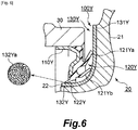
- Fig. 6 illustrates Embodiment 3 of the present invention.
- the present embodiment relates to a configuration where the pear-skin-like projections and depressions are provided on the slinger, while above described Embodiment 1 relates to a configuration where the pear-skin-like projections and depressions are provided on the seal lip of the seal body.
- Fig. 6 is a partially enlarged view of a schematic cross-sectional view of the hub bearing to which the sealing device of Embodiment 3 is applied.
- Fig. 6 illustrates a cross-sectional view obtained by cutting the hub bearing by a plane including the central axis of rotation of the inner ring.
- a description about a sealing device 100Y on the tire side (A), which is one of a pair of sealing devices provided in the hub bearing, will be given as an example (see Fig. 1 ).
- the sealing device 100Y has a reinforcement ring 110Y that is fixed to the outer ring 30, a seal body 120Y that is provided integrally with the reinforcement ring 110Y and is made of an elastic body, and a slinger 130Y that is fixed to the inner ring 20.
- the reinforcement ring 110Y is configured to be fixed to the inner peripheral surface of the outer ring 30 by fitting.
- the slinger 130Y is configured to be fixed to a portion in the vicinity of the curved surface between the outward flange portion 21 and the outer peripheral surface 22 in the inner ring 20 by fitting.
- the slinger 130Y includes an outward flange portion 131Y and a cylindrical portion 132Y.
- the seal body 120Y has a plurality of seal lips that are slidable on the slinger 130Y.
- the plurality of seal lips include the lip for foreign object for preventing the entry of the foreign object and a lip for grease 122Y for preventing the leakage of the grease.
- the lip for foreign object has a side lip 121Ya and a middle lip 121Yb that is provided between the side lip 121Ya and the lip for grease 122Y.
- Each of the side lip 121Ya and the middle lip 121Yb serving as the lip for foreign object extends radially outward and is slidable on the slinger 130Y.
- the side lip 121Ya is slidable on an end surface of the outward flange portion 131Y in the slinger 130Y
- the middle lip 121Yb is slidable on a curved surface between an outer peripheral surface of the cylindrical portion 132Y and the outward flange portion 131Y in the slinger 130Y.
- the lip for grease 122Y extends radially inward and is slidable on the outer peripheral surface of the cylindrical portion 132Y of the slinger 130Y.
- a surface of the slinger 130Y has the pear-skin-like projections and depressions in an area on which the lip for foreign object (the side lip 121Ya and the middle lip 121Yb) slides and in an area on which the lip for grease 122Y slides.
- Pear-skin-like projections and depressions 132Ya provided in the area on which the lip for grease 122Y slides are schematically illustrated in a circle in Fig. 6 .
- the pear-skin-like projections and depressions are projections and depressions that are randomly disposed, which are obtained by electrical discharge machining or blast machining.
- the roughness of the pear-skin-like projections and depressions in the area of the surface of the slinger 130Y on which the lip for grease 122Y slides is larger than the roughness of the pear-skin-like projections and depressions in the area of the surface of the slinger 130Y on which the lip for foreign object slides.
- the ten-point average height of irregularities of the pear-skin-like projections and depressions provided in the area on which the lip for foreign object slides is 10 ⁇ m
- the ten-point average height of irregularities of the pear-skin-like projections and depressions 132Ya provided in the area on which the lip for grease 122Y slides is larger than 10 ⁇ m.
- the ten-point average height of irregularities of the pear-skin-like projections and depressions is 15 ⁇ m or larger.
- the upper limit of the ten-point average height of irregularities of the pear-skin-like projections and depressions 132Ya is about 60 ⁇ m from the viewpoint of the fabrication method or the like.
- the sealing device 100Y of the present embodiment can achieve the similar effect as that of Embodiment 1 described above. Note that, the effect is expected to be obtained if the ten-point average height of irregularities of the pear-skin-like projections and depressions 132Ya provided in the area of the surface of the slinger 130Y on which the lip for grease 122Y slides is larger than 10 ⁇ m (e.g., 12 or 13 ⁇ m) as described in Embodiment 1.
- the similar effect is expected to be obtained if the ten-point average height of irregularities of the pear-skin-like projections and depressions 132Ya provided in the area of the surface of the slinger 130Y on which the lip for grease 122Y slides is larger than 10 ⁇ m and the ten-point average height of irregularities of the pear-skin-like projections and depressions provided in the area on which the lip for foreign object (the side lip 121Ya and the middle lip 121Yb) slides is equal to that of the area on which the lip for grease slides as described in Embodiment 1.
- Fig. 7 illustrates Embodiment 4 of the present invention.
- the present embodiment relates to a sealing device provided on the car body side, while each of above described embodiments relate to a sealing device provided on the tire side, which is one of a pair of sealing devices provided in the hub bearing.
- Fig. 7 is a partially enlarged view of a schematic cross-sectional view of the hub bearing to which the sealing device according to Embodiment 4 is applied.
- Fig. 7 illustrates a cross-sectional view obtained by cutting the hub bearing by a plane including the central axis of rotation of the inner ring.
- a description about the sealing device 200 provided on the car body side (B) will be given as an example, which is one of a pair of sealing devices provided in the hub bearing (see Fig. 1 ).
- the sealing device 200 has a reinforcement ring 210 that is fixed to the outer ring 30, a seal body 220 that is provided integrally with the reinforcement ring 210 and is made of an elastic body, and a slinger 230 that is fixed to the inner ring 20.
- the reinforcement ring 210 is configured to be fixed to the inner peripheral surface of the outer ring 30 by fitting.
- the slinger 230 is configured to be fixed to the outer peripheral surface of the inner ring 20 by fitting.
- the slinger 230 includes an outward flange portion 231 and a cylindrical portion 232. Note that the outward flange portion 231 has a rubber portion 240 having a magnetic pole that allows measurement of rotation speed of the inner ring 20.
- the seal body 220 has a plurality of seal lips that are slidable on the slinger 230.
- the plurality of seal lips include the lip for foreign object for preventing the entry of the foreign object and a lip for grease 222 for preventing the leakage of the grease.
- the lip for foreign object has a side lip 221a and a middle lip 221b that is provided between the side lip 221a and the lip for grease 222.
- the side lip 221a serving as the lip for foreign object extends radially outward and is slidable on the slinger 230.
- the side lip 221a is slidable on an end surface of the outward flange portion 231 in the slinger 230 and the middle lip 221b is slidable on an outer peripheral surface of the cylindrical portion 232 in the slinger 230.
- the lip for grease 222 extends radially inward and is slidable on the outer peripheral surface of the cylindrical portion 232 of the slinger 230.
- This configuration of the sealing device 200 may have, as Embodiment 1, pear-skin-like projections and depressions on each of a sliding surface in the lip for foreign object (the side lip 221a and the middle lip 221b) in the seal body 220 and a sliding surface in the lip for grease 222 in the seal body 220. Further, the roughness of the pear-skin-like projections and depressions provided on the sliding surface of the lip for grease 222 and the roughness of the pear-skin-like projections and depressions provided on the sliding surface of the lip for foreign object may be configured as described in Embodiment 1. This can achieve the similar effect as that of Embodiment 1.
- a surface of the slinger 230 of the sealing device 200 may have, as Embodiment 3, the pear-skin-like projections and depressions in an area on which the lip for foreign object (the side lip 221a and the middle lip 221b) slides and in an area on which the lip for grease 222 slides.
- the roughness of the pear-skin-like projections and depressions provided in the area of the surface of the slinger 230 on which the lip for grease 222 slides and the roughness of the pear-skin-like projections and depressions provided in the area of the surface of the slinger 230 on which the lip for foreign object slides may be configured as described in Embodiment 3. This can achieve the similar effect as that of Embodiment 3.
- the sealing device of the present invention may be applied to other than the hub bearing. That is, a sealing device similar to the sealing device described in each of the above described embodiments may be applied to other uses. For example, in a sealing device used in a differential device or a transmission, a problem where pressure in a sealed space between a lip for foreign object and a lubricant (grease or oil) lip becomes negative can occur.
- the sealing device according to the present invention may be applied to such sealing device.
Landscapes
- Engineering & Computer Science (AREA)
- General Engineering & Computer Science (AREA)
- Mechanical Engineering (AREA)
- Sealing Of Bearings (AREA)
- Rolling Contact Bearings (AREA)
- Sealing With Elastic Sealing Lips (AREA)
Abstract
Description
- The present invention relates to a sealing device provided in a hub bearing and a hub bearing.
- A hub bearing installed in an automobile is provided with sealing devices on each of a car body side and a tire side. Each of the sealing devices seals an annular gap between an inner ring and an outer ring provided in the hub bearing. The sealing device includes a lip for foreign object configured to prevent entry of a foreign object from the outside and a lip for grease configured to prevent leakage of grease. The lip for foreign object and the lip for grease are slidable on the inner ring or a slinger fixed to the inner ring.
- When the hub bearing is assembled, air can be trapped in a space between the sealing device on the car body side and the sealing device on the tire side, pressure in the space is increased, and the lip for grease is tightly pressed against the inner ring or the slinger fixed to the inner ring. This can prevent the air in the space from escaping to the outside.
- In addition, a surface of the inner ring or the slinger fixed to the inner ring has a spiral machining mark formed during polishing. This causes what is called a pumping effect when the lip slides on the inner ring which rotates relative to the outer ring, and then fluid in a sliding area of the lip moves in a direction depending on a rotation direction. In view of this, the spiral machining mark is typically formed such that a foreign object moves in a discharging direction to the outside when the inner ring rotates relative to the outer ring in a forward direction. Accordingly, when the inner ring rotates relative to the outer ring in the forward direction, gas in a sealed space between the lip for foreign object and the lip for grease is discharged to the outside. Thus, the gas in the sealed space is discharged to the outside from the sliding area of the lip for foreign object and, if air is not supplied from an inside space across the lip for grease, pressure in the sealed space becomes negative. Further, temperature may increase due to heat generation caused by sliding or the like, the gas in the sealed space may thereby thermally expand, and the gas in the sealed space may be discharged to the outside from the sliding area of the lip for foreign object. Also in this case, after decrease in the temperature, the gas in the sealed space contracts and the pressure in the sealed space becomes negative.
- Thus, each lip is tightly pressed against the inner ring or the like due to an increase in the pressure in the space between the sealing device on the car body side and the sealing device on the tire side and the negative pressure in the sealed space between the lip for foreign object and the lip for grease. It has been found that this causes sliding torque to increase.
- [PTL 1]
Japanese Patent Application Publication No.2010-185491 - An object of the present invention is to provide a sealing device and a hub bearing that can reduce sliding torque.
- In order to solve the above problem, the present invention has adopted the following means.
- That is, the sealing device of the present invention is a sealing device configured to seal an annular gap between an inner ring and an outer ring provided in a hub bearing, the sealing device including:
- a reinforcement ring configured to be fixed to the outer ring;
- a seal body that is provided integrally with the reinforcement ring and is made of an elastic body; and
- a plurality of seal lips provided in the seal body, the plurality of seal lips being slidable on the inner ring or a slinger fixed to the inner ring, wherein
- the plurality of seal lips include:
- a lip for foreign object configured to prevent entry of a foreign object which extends radially outward and is slidable on the inner ring or the slinger fixed to the inner ring; and
- a lip for grease configured to prevent leakage of grease which extends radially inward and is slidable on the inner ring or the slinger fixed to the inner ring;
- a sliding surface in the lip for foreign object and a sliding surface in the lip for grease have pear-skin-like projections and depressions on them; and
- roughness of the pear-skin-like projections and depressions provided on the sliding surface of the lip for grease is larger than roughness of the pear-skin-like projections and depressions provided on the sliding surface of the lip for foreign object.
- The pear-skin-like projections and depressions are provided on each of the sliding surface in the lip for foreign object and the sliding surface in the lip for grease. This reduces sliding torque. In addition, the roughness of the pear-skin-like projections and depressions provided on the sliding surface of the lip for grease is larger than the roughness of the pear-skin-like projections and depressions provided on the sliding surface of the lip for foreign object. This causes gas to escape from an inside space across the lip for grease into a sealed space between the lip for foreign object and the lip for grease. Accordingly, pressure in the inside space across the lip for grease can be reduced. In addition, this prevents pressure in the sealed space between the lip for foreign object and the lip for grease from becoming negative. Consequently, it is possible to prevent each seal lip from being tightly pressed against the inner ring or the slinger fixed to the inner ring.
- A ten-point average height of irregularities of the pear-skin-like projections and depressions provided on the sliding surface of the lip for grease may be larger than 10 µm.
- Note that "the ten-point average height of irregularities" is based on JIS B0601: 1994. The same applies to the following description. It has been found that the pear-skin-like projections and depressions provided on the sliding surface of the lip for grease with the ten-point average height of irregularities larger than 10 µm allow gas to be supplied into the sealed space between the lip for foreign object and the lip for grease from the inside space across the lip for grease .
- Another aspect of the present invention is a sealing device configured to seal an annular gap between an inner ring and an outer ring provided in a hub bearing, the sealing device including:
- a reinforcement ring configured to be fixed to the outer ring;
- a seal body that is provided integrally with the reinforcement ring and is made of an elastic body; and
- a plurality of seal lips provided in the seal body, the plurality of seal lips being slidable on the inner ring or a slinger fixed to the inner ring, wherein
- the plurality of seal lips include:
- a lip for foreign object configured to prevent entry of a foreign object which extends radially outward and is slidable on the inner ring or the slinger fixed to the inner ring; and
- a lip for grease configured to prevent leakage of grease which extends radially inward and is slidable on the inner ring or the slinger fixed to the inner ring; and
- a sliding surface in the lip for grease has pear-skin-like projections and depressions having a ten-point average height of irregularities larger than 10 µm.
- It has been found that this allows gas to be supplied into the sealed space between the lip for foreign object and the lip for grease from the inside space across the lip for grease. This reduces the pressure in the inside space across the lip for grease. In addition, this prevents the pressure in the sealed space between the lip for foreign object and the lip for grease from becoming negative. Consequently, this prevents each seal lip from being tightly pressed against the inner ring or the slinger fixed to the inner ring.
- Still another aspect of the present invention is a sealing device configured to seal an annular gap between an inner ring and an outer ring provided in a hub bearing, the sealing device including:
- a reinforcement ring fixed to the outer ring;
- a seal body that is provided integrally with the reinforcement ring and is made of an elastic body;
- a slinger fixed to the inner ring; and
- a plurality of seal lips provided in the seal body, the plurality of seal lips being slidable on the slinger, wherein
- the plurality of seal lips include:
- a lip for foreign object configured to prevent entry of a foreign object which extends radially outward and is slidable on the slinger; and
- a lip for grease configured to prevent leakage of grease which extends radially inward and is slidable on the slinger;
- a surface of the slinger has pear-skin-like projections and depressions in an area on which the lip for foreign object slides and in an area on which the lip for grease slides; and
- roughness of the pear-skin-like projections and depressions in the area on which the lip for grease slides is larger than roughness of the pear-skin-like projections and depressions in the area on which the lip for foreign object slides.
- The surface of the slinger has the pear-skin-like projections and depressions in the area on which the lip for foreign object slides and in the area on which the lip for grease slides. This reduces sliding torque. In addition, the roughness of the pear-skin-like projections and depressions in the area on which the lip for grease slides is larger than the roughness of the pear-skin-like projections and depressions in the area on which the lip for foreign object slides. This causes gas to escape from the inside space across the lip for grease into the sealed space between the lip for foreign object and the lip for grease. This reduces the pressure in the inside space across the lip for grease. In addition, this prevents the pressure in the sealed space between the lip for foreign object and the lip for grease from becoming negative. Consequently, this prevents each seal lip from being tightly pressed against the slinger.
- A ten-point average height of irregularities of the pear-skin-like projections and depressions in the area of the surface of the slinger on which the lip for grease slides may be larger than 10 µm.
- It has been found that this allows gas to be supplied into the sealed space between the lip for foreign object and the lip for grease from the inside space across the lip for grease.
- Still another aspect of the present invention is a sealing device configured to seal an annular gap between an inner ring and an outer ring provided in a hub bearing, the sealing device including:
- a reinforcement ring fixed to the outer ring;
- a seal body that is provided integrally with the reinforcement ring and is made of an elastic body;
- a slinger fixed to the inner ring; and
- a plurality of seal lips provided in the seal body, the plurality of seal lips being slidable on the slinger, wherein
- the plurality of seal lips include:
- a lip for foreign object configured to prevent entry of a foreign object which extends radially outward and is slidable on the slinger; and
- a lip for grease configured to prevent leakage of grease which extends radially inward and is slidable on the slinger; and
- a surface of the slinger has pear-skin-like projections and depressions in an area on which the lip for grease slides, the pear-skin-like projections and depressions having a ten-point average height of irregularities larger than 10 µm.
- It has been found that this allows gas to be supplied into the sealed space between the lip for foreign object and the lip for grease from the inside space across the lip for grease. This reduces the pressure in the inside space across the lip for grease. In addition, this prevents the pressure in the sealed space between the lip for foreign object and the lip for grease from becoming negative. Consequently, this prevents each seal lip from being tightly pressed against the slinger.
- The hub bearing of the present invention is a hub bearing including:
- an inner ring;
- an outer ring; and
- a sealing device configured to seal an annular gap between the inner ring and the outer ring, wherein
- the sealing device includes:
- a reinforcement ring that is fixed to the outer ring;
- a seal body that is provided integrally with the reinforcement ring and is made of an elastic body; and
- a plurality of seal lips provided in the seal body, the plurality of seal lips being slidable on the inner ring, wherein
- the plurality of seal lips include:
- a lip for foreign object configured to prevent entry of a foreign object which extends radially outward and is slidable on the inner ring; and
- a lip for grease configured to prevent leakage of grease which extends radially inward and is slidable on the inner ring;
- a surface of the inner ring has pear-skin-like projections and depressions in an area on which the lip for foreign object slides and in an area on which the lip for grease slides; and
- roughness of the pear-skin-like projections and depressions in the area on which the lip for grease slides is larger than roughness of the pear-skin-like projections and depressions in the area on which the lip for foreign object slides.
- The surface of the inner ring has the pear-skin-like projections and depressions in the area on which the lip for foreign object slides and in the area on which the lip for grease slides. This reduces sliding torque. In addition, the roughness of the pear-skin-like projections and depressions in the area on which the lip for grease slides is larger than the roughness of the pear-skin-like projections and depressions in the area on which the lip for foreign object slides. This causes gas to escape from the inside space across the lip for grease into the sealed space between the lip for foreign object and the lip for grease. This reduces the pressure in the inside space across the lip for grease. In addition, this prevents the pressure in the sealed space between the lip for foreign object and the lip for grease from becoming negative. Consequently, this prevents each seal lip from being tightly pressed against the inner ring.
- A ten-point average height of irregularities of the pear-skin-like projections and depressions in the area of the surface of the inner ring on which the lip for grease slides may be larger than 10 µm.
- It has been found that this allows gas to be supplied into the sealed space between the lip for foreign object and the lip for grease from the inside space across the lip for grease.
- Still another aspect of the present invention is a hub bearing including:
- an inner ring;
- an outer ring; and
- a sealing device configured to seal an annular gap between the inner ring and the outer ring, wherein
- the sealing device includes:
- a reinforcement ring that is fixed to the outer ring;
- a seal body that is provided integrally with the reinforcement ring and is made of an elastic body; and
- a plurality of seal lips provided in the seal body, the plurality of seal lips being slidable on the inner ring, wherein
- the plurality of seal lips include:
- a lip for foreign object configured to prevent entry of a foreign object which extends radially outward and is slidable on the inner ring; and
- a lip for grease configured to prevent leakage of grease which extends radially inward and is slidable on the inner ring; and
- a surface of the inner ring has pear-skin-like projections and depressions in an area on which the lip for grease slides, the pear-skin-like projections and depressions having a ten-point average height of irregularities larger than 10 µm.
- It has been found that this allows gas to be supplied into the sealed space between the lip for foreign object and the lip for grease from the inside space across the lip for grease. This reduces the pressure in the inside space across the lip for grease. In addition, this prevents the pressure in the sealed space between the lip for foreign object and the lip for grease from becoming negative. Consequently, this prevents each seal lip from being tightly pressed against the inner ring.
- As described above, the present invention can reduce sliding torque.
-
- [
Fig. 1 ]
Fig. 1 is a schematic cross-sectional view of a hub bearing according to an embodiment of the present invention. - [
Fig. 2 ]
Fig. 2 is a part of a schematic cross-sectional view of a sealing device according to Embodiment 1 of the present invention. - [
Fig. 3 ]
Fig. 3 is a partially enlarged view of a schematic cross-sectional view of the hub bearing to which the sealing device according to Embodiment 1 of the present invention is applied. - [
Fig. 4 ]
Fig. 4 is a graph showing a relationship between the number of cycles and a torque relative value. - [
Fig. 5 ]
Fig. 5 is a partially cutaway perspective view of the hub bearing to which the sealing device according toEmbodiment 2 of the present invention is applied. - [
Fig. 6 ]
Fig. 6 is a partially enlarged view of a schematic cross-sectional view of the hub bearing to which the sealing device according toEmbodiment 3 of the present invention is applied. - [
Fig. 7 ]
Fig. 7 is a partially enlarged view of a schematic cross-sectional view of the hub bearing to which the sealing device according toEmbodiment 4 of the present invention is applied. - Hereinbelow, with reference to the drawings, modes for carrying out the invention will be described in detail based on embodiments illustratively. It should be noted that, however, unless otherwise described specifically, the dimensions, materials, shapes, and relative arrangements of components described in the embodiments are not intended to limit the scope of the present invention to the dimensions, materials, shapes, and relative arrangements thereof.
- A hub bearing to which a sealing device is applied will be described with reference to
Fig. 1. Fig. 1 is a schematic cross-sectional view of a hub bearing.Fig. 1 shows a cross-sectional view obtained by cutting the hub bearing by a plane including the central axis of rotation of an inner ring. - An automobile includes a
hub bearing 10. Thehub bearing 10 includes an inner ring (shaft) 20, an outer ring (housing) 30 that are rotatable relative to each other, and a plurality ofballs 40 that are provided between theinner ring 20 and theouter ring 30. A tire (not shown) is fixed to theinner ring 20 side. Theouter ring 30 is mounted to a car body side. Hereinafter, for the convenience of description, the right side inFig. 1 is referred to as a tire side (A) and the left side therein is referred to as a car body side (B). Theinner ring 20 has anoutward flange portion 21 for mounting the tire on the tire side (A). In addition, in order to prevent entry of a foreign object (muddy water, garbage, or the like) into the hub bearing 10 from the outside and prevent leakage of grease (G) serving as lubricant from the inside, sealingdevices inner ring 20 and theouter ring 30 are provided. Thesealing device 100 on the tire side (A) may be referred to as an outer seal and thesealing device 200 on the car body side (B) may be referred to as an inner seal. - The
sealing device 100 on the tire side (A) and thesealing device 200 on the car body side (B) may adopt basically the same configuration. Note that each of the sealingdevices inner ring 20 such that the foreign object or the like is easily discharged to the outside by a centrifugal force as theinner ring 20 rotates. Thesealing device 100 on the tire side may be provided with a seal lip that slides on theoutward flange portion 21. On the other hand, thesealing device 200 on the car body side (B) may be typically provided with a slinger (annular member) in order to provide a portion corresponding to theoutward flange portion 21. Thus, the sealingdevices sealing device 200 on the car body side (B), the slinger is not necessarily required in thesealing device 100 on the tire side (A). - The sealing device and the hub bearing will be described with reference to
Figs. 2 to 4 .Fig. 2 is a part of a schematic cross-sectional view of the sealing device.Fig. 3 is a partially enlarged view of a schematic cross-sectional view of the hub bearing to which the sealing device is applied.Figs. 2 and3 show cross-sectional views obtained by cutting the sealing device and the hub bearing by a plane including the central axis of rotation of the inner ring.Fig. 4 is a graph showing a relationship between the number of cycles and a torque relative value. - A description about the
sealing device 100 on the tire side (A) will be given as an example. Thesealing device 100 has areinforcement ring 110 that is fixed to theouter ring 30 and aseal body 120 that is provided integrally with thereinforcement ring 110 and is made of an elastic body. Thereinforcement ring 110 is configured to be fixed to an inner peripheral surface of theouter ring 30 by fitting (seeFig. 3 ). - The
seal body 120 has a plurality of seal lips that are slidable on theinner ring 20. The plurality of seal lips include a lip for foreign object for preventing entry of a foreign object and a lip for grease (lip for lubricant) 122 for preventing leakage of grease (G). The lip for foreign object has aside lip 121a and amiddle lip 121b that is provided between theside lip 121a and the lip forgrease 122. Each of theside lip 121a and themiddle lip 121b that serve as the lip for foreign object extends radially outward and is slidable on theinner ring 20. Theside lip 121a is slidable on an end surface of theoutward flange portion 21 in theinner ring 20 and themiddle lip 121b is slidable on a curved surface between an outerperipheral surface 22 and theoutward flange portion 21 of theinner ring 20. The lip forgrease 122 extends radially inward and is slidable on the outerperipheral surface 22 of theinner ring 20. - The
seal body 120 has alabyrinth seal 123 in a radially outside space across theside lip 121a. Thelabyrinth seal 123 is configured not to slide on theinner ring 20. Between thelabyrinth seal 123 and the end surface of theoutward flange portion 21 in theinner ring 20 is formed a small gap. Thelabyrinth seal 123 does not cause sliding torque. Thelabyrinth seal 123 prevents the entry of the foreign object such as muddy water. - The
seal body 120 has pear-skin-like projections and depressions on each of a sliding surface in the lip for foreign object (theside lip 121a and themiddle lip 121b) and a sliding surface in the lip forgrease 122. Pear-skin-like projections anddepressions 122a provided on the sliding surface of the lip forgrease 122 are schematically shown in a circle inFig. 3 . The pear-skin-like projections and depressions are projections and depressions that are randomly disposed, which are obtained by electrical discharge machining or blast machining. The pear-skin-like projections and depressions may be produced by directly machining an object. The pear-skin-like projections and depressions provided on theseal body 120 may be produced with high productivity by using a mold for molding theseal body 120 which is provided with pear-skin-like projections and depressions on its surface. - The roughness of the pear-skin-like projections and
depressions 122a provided on the sliding surface of the lip forgrease 122 is larger than the roughness of the pear-skin-like projections and depressions provided on the sliding surface of the lip for foreign object. Specifically, the ten-point average height of irregularities of the pear-skin-like projections and depressions provided on the sliding surface of the lip for foreign object is 10 µm. Note that "the ten-point average height of irregularities" is based on JIS B0601: 1994. The same applies to the following description. The ten-point average height of irregularities of the pear-skin-like projections anddepressions 122a provided on the sliding surface of the lip forgrease 122 is larger than 10 µm. Note that it is difficult to control the ten-point average height of irregularities of the pear-skin-like projections and depressions in the order of µm due to limitation of fabrication method. In view of this, the ten-point average height of irregularities of the pear-skin-like projections anddepressions 122a provided on the sliding surface of the lip forgrease 122 is 15 µm or larger. Note that the upper limit of the ten-point average height of irregularities of the pear-skin-like projections anddepressions 122a is about 60 µm from the viewpoint of the fabrication method or the like. However, the ten-point average height of irregularities of the pear-skin-like projections anddepressions 122a provided on the sliding surface of the lip forgrease 122 may be larger than 60 µm as long as the lip forgrease 122 can prevent the leakage of the grease, which is its intended function. - The pear-skin-like projections and depressions are provided on each of the sliding surface in the lip for foreign object (the
side lip 121a and themiddle lip 121b) of theseal body 120 and the sliding surface in the lip forgrease 122 thereof in thesealing device 100 and thehub bearing 10. This can reduce sliding torque. - The roughness of the pear-skin-like projections and
depressions 122a provided on the sliding surface of the lip forgrease 122 is larger than the roughness of the pear-skin-like projections and depressions provided on the sliding surface of the lip for foreign object. This can cause gas to escape from an inside space across the lip forgrease 122 into a sealed space between the lip for foreign object and the lip forgrease 122. This can reduce pressure in the inside space across the lip forgrease 122. This can prevent pressure in the sealed space between the lip for foreign object and the lip forgrease 122 from becoming negative. Consequently, this can prevent each seal lip from being tightly pressed against theinner ring 20. A test result related to this will be described. - A comparison test for measuring change of torque was conducted on the
sealing device 100 and a sealing device of a comparative example. The basic configuration of thesealing device 100 is identical to that of the sealing device of the comparative example. The ten-point average height of irregularities of the pear-skin-like projections and depressions provided on the sliding surface in the lip for foreign object (theside lip 121a and themiddle lip 121b) of theseal body 120 was set to 10 µm both for thesealing device 100 and for the sealing device of a comparative example. In contrast to this, the ten-point average height of irregularities of the pear-skin-like projections anddepressions 122a provided on the sliding surface of the lip forgrease 122 of thesealing device 100 was set to 15 µm, while that of the sealing device of a comparative example was set to 10 µm. - Average values of sliding torque were measured in multiple cycles of operation in which the
inner ring 20 was rotated for 60 minutes while the RPM was changed in two stages (rotation at 1000 rpm after a running-in at 100 rpm). A graph inFig. 4 illustrates the change of torque relative to the average value of the torque in the first cycle of the operation conducted on thesealing device 100. Circles in the graph represent values measured on the sealing device 100 (the ten-point average height of irregularities of the pear-skin-like projections anddepressions 122a provided on the sliding surface of the lip forgrease 122 is 15 µm) Boxes in the graph represent values measured on the comparative example (the ten-point average height of irregularities is 10 µm). - The graph in
Fig. 4 shows that there is little change in the torque of thesealing device 100 with increase in cycles. In contrast to this, the torque of the sealing device of the comparative example is high even in the first cycle and, as the number of cycles increases, the torque begins to increase. This may be caused by an increase in a pressing force that pressed each seal lip against the inner ring due to high pressure in the inside space across the lip for grease which was kept high and gradual decrease in the pressure in the sealed space between the lip for foreign object and the lip for grease. - Note that, it is difficult to control the ten-point average height of irregularities of the pear-skin-like projections and depressions in the order of µm due to limitation of the fabrication method. It is technically difficult to perform similar comparisons by varying the ten-point average height of irregularities of the pear-skin-like projections and
depressions 122a provided on the sliding surface of the lip forgrease 122 in the order of µm. However, the similar effect is expected to be obtained if the ten-point average height of irregularities of the pear-skin-like projections anddepressions 122a is larger than 10 µm (e.g., 12 or 13 µm). - Further, the similar effect is expected to be obtained if the ten-point average height of irregularities of the pear-skin-like projections and
depressions 122a provided on the sliding surface of the lip forgrease 122 is larger than 10 µm and the ten-point average height of irregularities of the pear-skin-like projections and depressions provided on the sliding surface in the lip for foreign object (theside lip 121a and themiddle lip 121b) is equal to that of the lip for grease. -
Fig. 5 illustratesEmbodiment 2 of the present invention. The present embodiment relates to a configuration where the pear-skin-like projections and depressions are provided on the inner ring, while above described Embodiment 1 relates to a configuration where the pear-skin-like projections and depressions are provided on the seal lip of the seal body. - The overall configuration of the hub bearing is same as above described embodiment and hence further explanation will be omitted.
Fig. 5 is a partially cutaway perspective view of the hub bearing to which the sealing device ofEmbodiment 2 is applied. Note that, inFig. 5 , the outer ring is omitted in order for easy understanding of the configuration of the sealing device. A description about asealing device 100X on the tire side (A), which is one of a pair of sealing devices provided in the hub bearing, will be given as an example (seeFig. 1 ). Thesealing device 100X has areinforcement ring 110X that is fixed to the outer ring and aseal body 120X that is provided integrally with thereinforcement ring 110X and is made of an elastic body. Thereinforcement ring 110X is configured to be fixed to the inner peripheral surface of the outer ring by fitting. - The
seal body 120X has a plurality of seal lips that are slidable on theinner ring 20. The plurality of seal lips include the lip for foreign object for preventing the entry of the foreign object and a lip forgrease 122X for preventing the leakage of the grease. The lip for foreign object has a side lip 121Xa and a middle lip 121Xb that is provided between the side lip 121Xa and the lip forgrease 122X. Each of the side lip 121Xa and the middle lip 121Xb serving as the lip for foreign object extends radially outward and is slidable on theinner ring 20. The side lip 121Xa is slidable on the end surface of theoutward flange portion 21 in theinner ring 20 and the middle lip 121Xb is slidable on the curved surface between the outerperipheral surface 22 and theoutward flange portion 21 of theinner ring 20. The lip forgrease 122X extends radially inward and is slidable on the outerperipheral surface 22 of theinner ring 20. - A surface of the
inner ring 20 has the pear-skin-like projections and depressions in an area on which the lip for foreign object (the side lip 121Xa and the middle lip 121Xb) slides and an area on which the lip forgrease 122X slides. Pear-skin-like projections anddepressions 22a provided in the area on which the lip forgrease 122X slides are schematically illustrated in a circle inFig. 5 . As described in Embodiment 1, the pear-skin-like projections and depressions are projections and depressions that are randomly disposed, which are obtained by electrical discharge machining or blast machining. - The roughness of the pear-skin-like projections and depressions in the area of the surface of the
inner ring 20 on which the lip forgrease 122X slides is larger than the roughness of the pear-skin-like projections and depressions in the area of the surface of theinner ring 20 on which the lip for foreign object slides. Specifically, the ten-point average height of irregularities of the pear-skin-like projections and depressions provided in the area on which the lip for foreign object slides is 10 µm, while the ten-point average height of irregularities of the pear-skin-like projections anddepressions 22a provided in the area on which the lip forgrease 122X slides is larger than 10 µm. Note that it is difficult to control the ten-point average height of irregularities of the pear-skin-like projections and depressions in the order of µm due to limitation of the fabrication method. In view of this, the ten-point average height of irregularities of the pear-skin-like projections anddepressions 22a provided in the area on which the lip forgrease 122X slides is 15 µm or larger. Note that, as described in Embodiment 1, the upper limit of the ten-point average height of irregularities of the pear-skin-like projections anddepressions 22a is about 60 µm from the viewpoint of the fabrication method or the like. - The hub bearing of the present embodiment can achieve the similar effect as that of Embodiment 1 described above. Note that the effect is expected to be obtained if the ten-point average height of irregularities of the pear-skin-like projections and
depressions 22a provided in the area of the surface of theinner ring 20 on which the lip forgrease 122X slides is larger than 10 µm (e.g., 12 or 13 µm) as described in Embodiment 1. Further, the similar effect is expected to be obtained if the ten-point average height of irregularities of the pear-skin-like projections anddepressions 22a provided in the area of the surface of theinner ring 20 on which the lip forgrease 122 slides is larger than 10 µm and the ten-point average height of irregularities of the pear-skin-like projections and depressions provided in the area on which the lip for foreign object (the side lip 121Xa and the middle lip 121Xb) slides is equal to that of the area on which the lip for grease slides as described in Embodiment 1. -
Fig. 6 illustratesEmbodiment 3 of the present invention. The present embodiment relates to a configuration where the pear-skin-like projections and depressions are provided on the slinger, while above described Embodiment 1 relates to a configuration where the pear-skin-like projections and depressions are provided on the seal lip of the seal body. - The overall configuration of the hub bearing is same as above described embodiment and hence further explanation will be omitted.
Fig. 6 is a partially enlarged view of a schematic cross-sectional view of the hub bearing to which the sealing device ofEmbodiment 3 is applied.Fig. 6 illustrates a cross-sectional view obtained by cutting the hub bearing by a plane including the central axis of rotation of the inner ring. A description about asealing device 100Y on the tire side (A), which is one of a pair of sealing devices provided in the hub bearing, will be given as an example (seeFig. 1 ). Thesealing device 100Y has areinforcement ring 110Y that is fixed to theouter ring 30, aseal body 120Y that is provided integrally with thereinforcement ring 110Y and is made of an elastic body, and aslinger 130Y that is fixed to theinner ring 20. Thereinforcement ring 110Y is configured to be fixed to the inner peripheral surface of theouter ring 30 by fitting. Theslinger 130Y is configured to be fixed to a portion in the vicinity of the curved surface between theoutward flange portion 21 and the outerperipheral surface 22 in theinner ring 20 by fitting. Theslinger 130Y includes anoutward flange portion 131Y and acylindrical portion 132Y. - The
seal body 120Y has a plurality of seal lips that are slidable on theslinger 130Y. The plurality of seal lips include the lip for foreign object for preventing the entry of the foreign object and a lip forgrease 122Y for preventing the leakage of the grease. The lip for foreign object has a side lip 121Ya and a middle lip 121Yb that is provided between the side lip 121Ya and the lip forgrease 122Y. Each of the side lip 121Ya and the middle lip 121Yb serving as the lip for foreign object extends radially outward and is slidable on theslinger 130Y. The side lip 121Ya is slidable on an end surface of theoutward flange portion 131Y in theslinger 130Y The middle lip 121Yb is slidable on a curved surface between an outer peripheral surface of thecylindrical portion 132Y and theoutward flange portion 131Y in theslinger 130Y. The lip forgrease 122Y extends radially inward and is slidable on the outer peripheral surface of thecylindrical portion 132Y of theslinger 130Y. - A surface of the
slinger 130Y has the pear-skin-like projections and depressions in an area on which the lip for foreign object (the side lip 121Ya and the middle lip 121Yb) slides and in an area on which the lip forgrease 122Y slides. Pear-skin-like projections and depressions 132Ya provided in the area on which the lip forgrease 122Y slides are schematically illustrated in a circle inFig. 6 . As described in Embodiment 1, the pear-skin-like projections and depressions are projections and depressions that are randomly disposed, which are obtained by electrical discharge machining or blast machining. - The roughness of the pear-skin-like projections and depressions in the area of the surface of the
slinger 130Y on which the lip forgrease 122Y slides is larger than the roughness of the pear-skin-like projections and depressions in the area of the surface of theslinger 130Y on which the lip for foreign object slides. Specifically, the ten-point average height of irregularities of the pear-skin-like projections and depressions provided in the area on which the lip for foreign object slides is 10 µm, while the ten-point average height of irregularities of the pear-skin-like projections and depressions 132Ya provided in the area on which the lip forgrease 122Y slides is larger than 10 µm. Note that it is difficult to control the ten-point average height of irregularities of the pear-skin-like projections and depressions in the order of µm due to limitation of the fabrication method. In view of this, the ten-point average height of irregularities of the pear-skin-like projections and depressions 132Ya provided in the area on which the lip forgrease 122Y slides is 15 µm or larger. Note that, as described in Embodiment 1, the upper limit of the ten-point average height of irregularities of the pear-skin-like projections and depressions 132Ya is about 60 µm from the viewpoint of the fabrication method or the like. - The
sealing device 100Y of the present embodiment can achieve the similar effect as that of Embodiment 1 described above. Note that, the effect is expected to be obtained if the ten-point average height of irregularities of the pear-skin-like projections and depressions 132Ya provided in the area of the surface of theslinger 130Y on which the lip forgrease 122Y slides is larger than 10 µm (e.g., 12 or 13 µm) as described in Embodiment 1. Further, the similar effect is expected to be obtained if the ten-point average height of irregularities of the pear-skin-like projections and depressions 132Ya provided in the area of the surface of theslinger 130Y on which the lip forgrease 122Y slides is larger than 10 µm and the ten-point average height of irregularities of the pear-skin-like projections and depressions provided in the area on which the lip for foreign object (the side lip 121Ya and the middle lip 121Yb) slides is equal to that of the area on which the lip for grease slides as described in Embodiment 1. -
Fig. 7 illustratesEmbodiment 4 of the present invention. The present embodiment relates to a sealing device provided on the car body side, while each of above described embodiments relate to a sealing device provided on the tire side, which is one of a pair of sealing devices provided in the hub bearing. - The overall configuration of the hub bearing is same as above described embodiment and hence further explanation will be omitted.
Fig. 7 is a partially enlarged view of a schematic cross-sectional view of the hub bearing to which the sealing device according toEmbodiment 4 is applied.Fig. 7 illustrates a cross-sectional view obtained by cutting the hub bearing by a plane including the central axis of rotation of the inner ring. A description about thesealing device 200 provided on the car body side (B) will be given as an example, which is one of a pair of sealing devices provided in the hub bearing (seeFig. 1 ). Thesealing device 200 has areinforcement ring 210 that is fixed to theouter ring 30, aseal body 220 that is provided integrally with thereinforcement ring 210 and is made of an elastic body, and aslinger 230 that is fixed to theinner ring 20. Thereinforcement ring 210 is configured to be fixed to the inner peripheral surface of theouter ring 30 by fitting. Theslinger 230 is configured to be fixed to the outer peripheral surface of theinner ring 20 by fitting. Theslinger 230 includes anoutward flange portion 231 and acylindrical portion 232. Note that theoutward flange portion 231 has arubber portion 240 having a magnetic pole that allows measurement of rotation speed of theinner ring 20. - The
seal body 220 has a plurality of seal lips that are slidable on theslinger 230. The plurality of seal lips include the lip for foreign object for preventing the entry of the foreign object and a lip forgrease 222 for preventing the leakage of the grease. The lip for foreign object has aside lip 221a and amiddle lip 221b that is provided between theside lip 221a and the lip forgrease 222. Theside lip 221a serving as the lip for foreign object extends radially outward and is slidable on theslinger 230. Theside lip 221a is slidable on an end surface of theoutward flange portion 231 in theslinger 230 and themiddle lip 221b is slidable on an outer peripheral surface of thecylindrical portion 232 in theslinger 230. The lip forgrease 222 extends radially inward and is slidable on the outer peripheral surface of thecylindrical portion 232 of theslinger 230. - This configuration of the
sealing device 200 may have, as Embodiment 1, pear-skin-like projections and depressions on each of a sliding surface in the lip for foreign object (theside lip 221a and themiddle lip 221b) in theseal body 220 and a sliding surface in the lip forgrease 222 in theseal body 220. Further, the roughness of the pear-skin-like projections and depressions provided on the sliding surface of the lip forgrease 222 and the roughness of the pear-skin-like projections and depressions provided on the sliding surface of the lip for foreign object may be configured as described in Embodiment 1. This can achieve the similar effect as that of Embodiment 1. - A surface of the
slinger 230 of thesealing device 200 may have, asEmbodiment 3, the pear-skin-like projections and depressions in an area on which the lip for foreign object (theside lip 221a and themiddle lip 221b) slides and in an area on which the lip forgrease 222 slides. The roughness of the pear-skin-like projections and depressions provided in the area of the surface of theslinger 230 on which the lip forgrease 222 slides and the roughness of the pear-skin-like projections and depressions provided in the area of the surface of theslinger 230 on which the lip for foreign object slides may be configured as described inEmbodiment 3. This can achieve the similar effect as that ofEmbodiment 3. - While each of the above described embodiments is an example of the sealing device applied to the hub bearing, the sealing device of the present invention may be applied to other than the hub bearing. That is, a sealing device similar to the sealing device described in each of the above described embodiments may be applied to other uses. For example, in a sealing device used in a differential device or a transmission, a problem where pressure in a sealed space between a lip for foreign object and a lubricant (grease or oil) lip becomes negative can occur. The sealing device according to the present invention may be applied to such sealing device.
-
- 10
- Hub bearing
- 20
- Inner ring
- 21
- Outward flange portion
- 22
- Outer peripheral surface
- 22a
- Projections and depressions
- 30
- Outer ring
- 40
- Ball
- 100, 100X, 100Y, 200
- Sealing device
- 110, 110X, 110Y, 210
- Reinforcement ring
- 120, 120X, 120Y, 220
- Seal body
- 121a, 121Xa, 121Ya, 221a
- Side lip
- 121b, 121Xb, 121Yb, 221b
- Middle lip
- 122, 122X, 122Y, 222
- Lip for grease
- 122a
- Projections and depressions
- 123
- Labyrinth seal
- 130Y, 230
- Slinger
- 131Y, 231
- Outward flange portion
- 132Y
- Cylindrical portion
- 132Ya
- Projections and depressions
- 232
- Cylindrical portion
- 240
- Rubber portion
Claims (15)
- A sealing device configured to seal an annular gap between an inner ring and an outer ring provided in a hub bearing, the sealing device comprising:a reinforcement ring configured to be fixed to the outer ring;a seal body that is provided integrally with the reinforcement ring and is made of an elastic body; anda plurality of seal lips provided in the seal body, the plurality of seal lips being slidable on the inner ring or a slinger fixed to the inner ring, whereinthe plurality of seal lips include:a lip for foreign object configured to prevent entry of a foreign object which extends radially outward and is slidable on the inner ring or the slinger fixed to the inner ring; anda lip for grease configured to prevent leakage of grease which extends radially inward and is slidable on the inner ring or the slinger fixed to the inner ring;a sliding surface in the lip for foreign object and a sliding surface in the lip for grease have pear-skin-like projections and depressions on them; androughness of the pear-skin-like projections and depressions provided on the sliding surface of the lip for grease is larger than roughness of the pear-skin-like projections and depressions provided on the sliding surface of the lip for foreign object.
- The sealing device according to Claim 1, wherein
a ten-point average height of irregularities of the pear-skin-like projections and depressions provided on the sliding surface of the lip for grease is larger than 10 µm. - A sealing device configured to seal an annular gap between an inner ring and an outer ring provided in a hub bearing, the sealing device comprising:a reinforcement ring configured to be fixed to the outer ring;a seal body that is provided integrally with the reinforcement ring and is made of an elastic body; anda plurality of seal lips provided in the seal body, the plurality of seal lips being slidable on the inner ring or a slinger fixed to the inner ring, whereinthe plurality of seal lips include:a lip for foreign object configured to prevent entry of a foreign object which extends radially outward and is slidable on the inner ring or the slinger fixed to the inner ring; anda lip for grease configured to prevent leakage of grease which extends radially inward and is slidable on the inner ring or the slinger fixed to the inner ring; anda sliding surface in the lip for grease has pear-skin-like projections and depressions having a ten-point average height of irregularities larger than 10 µm.
- A sealing device configured to seal an annular gap between an inner ring and an outer ring provided in a hub bearing, the sealing device comprising:a reinforcement ring fixed to the outer ring;a seal body that is provided integrally with the reinforcement ring and is made of an elastic body;a slinger fixed to the inner ring; anda plurality of seal lips provided in the seal body, the plurality of seal lips being slidable on the slinger, whereinthe plurality of seal lips include:a lip for foreign object configured to prevent entry of a foreign object which extends radially outward and is slidable on the slinger; anda lip for grease configured to prevent leakage of grease which extends radially inward and is slidable on the slinger;a surface of the slinger has pear-skin-like projections and depressions in an area on which the lip for foreign object slides and in an area on which the lip for grease slides; androughness of the pear-skin-like projections and depressions in the area on which the lip for grease slides is larger than roughness of the pear-skin-like projections and depressions in the area on which the lip for foreign object slides.
- The sealing device according to Claim 4, wherein
a ten-point average height of irregularities of the pear-skin-like projections and depressions in the area of the surface of the slinger on which the lip for grease slides is larger than 10 µm. - A sealing device configured to seal an annular gap between an inner ring and an outer ring provided in a hub bearing, the sealing device comprising:a reinforcement ring configured to be fixed to the outer ring;a seal body that is provided integrally with the reinforcement ring and is made of an elastic body;a slinger fixed to the inner ring; anda plurality of seal lips provided in the seal body, the plurality of seal lips being slidable on the slinger, whereinthe plurality of seal lips include:a lip for foreign object configured to prevent entry of a foreign object which extends radially outward and is slidable on the slinger; anda lip for grease configured to prevent leakage of grease which extends radially inward and is slidable on the slinger; anda surface of the slinger has pear-skin-like projections and depressions in an area on which the lip for grease slides, the pear-skin-like projections and depressions having a ten-point average height of irregularities larger than 10 µm.
- A hub bearing comprising:an inner ring;an outer ring; anda sealing device configured to seal an annular gap between the inner ring and the outer ring, whereinthe sealing device includes:a reinforcement ring that is configured to be fixed to the outer ring;a seal body that is provided integrally with the reinforcement ring and is made of an elastic body; anda plurality of seal lips provided in the seal body, the plurality of seal lips being slidable on the inner ring, whereinthe plurality of seal lips include:a lip for foreign object configured to prevent entry of a foreign object which extends radially outward and is slidable on the inner ring; anda lip for grease configured to prevent leakage of grease which extends radially inward and is slidable on the inner ring;a surface of the inner ring has pear-skin-like projections and depressions in an area on which the lip for foreign object slides and in an area on which the lip for grease slides; androughness of the pear-skin-like projections and depressions in the area on which the lip for grease slides is larger than roughness of the pear-skin-like projections and depressions in the area on which the lip for foreign object slides.
- The hub bearing according to Claim 7, wherein
a ten-point average height of irregularities of the pear-skin-like projections and depressions in the area of the surface of the inner ring on which the lip for grease slides is larger than 10 µm. - A hub bearing comprising:an inner ring;an outer ring; anda sealing device configured to seal an annular gap between the inner ring and the outer ring, whereinthe sealing device includes:a reinforcement ring that is fixed to the outer ring;a seal body that is provided integrally with the reinforcement ring and is made of an elastic body; anda plurality of seal lips provided in the seal body, the plurality of seal lips being slidable on the inner ring, whereinthe plurality of seal lips include:a lip for foreign object configured to prevent entry of a foreign object which extends radially outward and is slidable on the inner ring; anda lip for grease configured to prevent leakage of grease which extends radially inward and is slidable on the inner ring; anda surface of the inner ring has pear-skin-like projections and depressions in an area on which the lip for grease slides, the pear-skin-like projections and depressions having a ten-point average height of irregularities of larger than 10 µm.
- A sealing device configured to seal an annular gap between a shaft and a housing rotatable relative to each other, the sealing device comprising:a reinforcement ring fixed to the housing;a seal body that is provided integrally with the reinforcement ring and is made of an elastic body; anda plurality of seal lips provided in the seal body, the plurality of seal lips being slidable on the shaft or an annular member fixed to the shaft, whereinthe plurality of seal lips include:a lip for foreign object configured to prevent entry of a foreign object which extends radially outward and is slidable on the shaft or the annular member fixed to the shaft; anda lip for lubricant configured to prevent leakage of lubricant which extends radially inward and is slidable on the shaft or the annular member fixed to the shaft;each of a sliding surface in the lip for foreign object and a sliding surface in the lip for lubricant has pear-skin-like projections and depressions thereon; androughness of the pear-skin-like projections and depressions provided on the sliding surface of the lip for lubricant is larger than roughness of the pear-skin-like projections and depressions provided on the sliding surface of the lip for foreign object.
- The sealing device according to Claim 10, wherein
a ten-point average height of irregularities of the pear-skin-like projections and depressions provided on the sliding surface of the lip for lubricant is larger than 10 µm. - A sealing device configured to seal an annular gap between a shaft and a housing rotatable relative to each other, the sealing device comprising:a reinforcement ring configured to be fixed to the housing;a seal body that is provided integrally with the reinforcement ring and is made of an elastic body; anda plurality of seal lips provided in the seal body, the plurality of seal lips being slidable on the shaft or an annular member fixed to the shaft, whereinthe plurality of seal lips include:a lip for foreign object configured to prevent entry of a foreign object which extends radially outward and is slidable on the shaft or the annular member fixed to the shaft; anda lip for lubricant configured to prevent leakage of lubricant which extends radially inward and is slidable on the shaft or the annular member fixed to the shaft; anda sliding surface in the lip for lubricant has pear-skin-like projections and depressions having a ten-point average height of irregularities of larger than 10 µm.
- A sealing device configured to seal an annular gap between a shaft and a housing rotatable relative to each other, the sealing device comprising:a reinforcement ring configured to be fixed to the housing;a seal body that is provided integrally with the reinforcement ring and is made of an elastic body;an annular member configured to be fixed to the shaft; anda plurality of seal lips provided in the seal body, the plurality of seal lips being slidable on the annular member, whereinthe plurality of seal lips include:a lip for foreign object configured to prevent entry of a foreign object which extends radially outward and is slidable on the annular member; anda lip for lubricant configured to prevent leakage of lubricant which extends radially inward and is slidable on the annular member;a surface of the annular member has pear-skin-like projections and depressions in an area on which the lip for foreign object slides and in an area on which the lip for lubricant slides; androughness of the pear-skin-like projections and depressions in the area in which the lip for lubricant slides is larger than roughness of the pear-skin-like projections and depressions in the area on which the lip for foreign object slides.
- The sealing device according to Claim 13, wherein
a ten-point average height of irregularities of the pear-skin-like projections and depressions in the area of the surface of the annular member on which the lip for lubricant slides is larger than 10 µm. - A sealing device configured to seal an annular gap between a shaft and a housing rotatable relative to each other, the sealing device comprising:a reinforcement ring configured to be fixed to the housing;a seal body that is provided integrally with the reinforcement ring and is made of an elastic body;an annular member configured to be fixed to the shaft; anda plurality of seal lips provided in the seal body, the plurality of seal lips being slidable on the annular member, whereinthe plurality of seal lips include:a lip for foreign object configured to prevent entry of a foreign object which extends radially outward and is slidable on the annular member; anda lip for lubricant configured to prevent leakage of lubricant which extends radially inward and is slidable on the annular member; anda surface of the annular member has pear-skin-like projections and depressions in an area of on which the lip for lubricant slides, the pear-skin-like projections and depressions having a ten-point average height of irregularities of larger than 10 µm.
Applications Claiming Priority (2)
| Application Number | Priority Date | Filing Date | Title |
|---|---|---|---|
| JP2016229416 | 2016-11-25 | ||
| PCT/JP2017/042171 WO2018097233A1 (en) | 2016-11-25 | 2017-11-24 | Sealing device and hub bearing |
Publications (3)
| Publication Number | Publication Date |
|---|---|
| EP3546776A1 true EP3546776A1 (en) | 2019-10-02 |
| EP3546776A4 EP3546776A4 (en) | 2020-07-22 |
| EP3546776B1 EP3546776B1 (en) | 2021-06-16 |
Family
ID=62195103
Family Applications (1)
| Application Number | Title | Priority Date | Filing Date |
|---|---|---|---|
| EP17872919.0A Active EP3546776B1 (en) | 2016-11-25 | 2017-11-24 | Sealing device and hub bearing |
Country Status (5)
| Country | Link |
|---|---|
| US (1) | US10794428B2 (en) |
| EP (1) | EP3546776B1 (en) |
| JP (1) | JP6673500B2 (en) |
| CN (1) | CN109983244B (en) |
| WO (1) | WO2018097233A1 (en) |
Cited By (3)
| Publication number | Priority date | Publication date | Assignee | Title |
|---|---|---|---|---|
| WO2022089777A1 (en) * | 2020-10-29 | 2022-05-05 | Sew-Eurodrive Gmbh & Co. Kg | Shaft sealing ring having lips, gearbox having a shaft sealing ring, and method for lubricating a shaft sealing ring |
| EP4328461A1 (en) * | 2022-08-23 | 2024-02-28 | NOK Corporation | Sealing device for hub bearing |
| CN117628072A (en) * | 2022-08-23 | 2024-03-01 | Nok株式会社 | Sealing device for wheel hub bearing |
Families Citing this family (8)
| Publication number | Priority date | Publication date | Assignee | Title |
|---|---|---|---|---|
| CN110036214B (en) * | 2016-11-25 | 2020-11-24 | Nok株式会社 | Sealing device and sealing structure |
| JP6899456B2 (en) * | 2018-07-03 | 2021-07-07 | Nok株式会社 | Sealing device |
| CN111386414B (en) * | 2018-10-31 | 2022-12-13 | Nok株式会社 | Surface processing method for disc member of sealing device and sealing device |
| JP7203862B2 (en) | 2018-11-29 | 2023-01-13 | Nok株式会社 | sealing device |
| JP2020122492A (en) * | 2019-01-29 | 2020-08-13 | 中西金属工業株式会社 | Manufacturing method of slinger for use in rotation seal and rotation seal |
| JP7417973B2 (en) * | 2019-03-18 | 2024-01-19 | 内山工業株式会社 | bearing sealing device |
| CN112833182A (en) * | 2021-01-11 | 2021-05-25 | 黄山中乔汽车零配件有限公司 | A sealing ring assembly |
| CN116989065A (en) * | 2023-09-27 | 2023-11-03 | 万向钱潮股份公司 | Sealing assembly for bearing and hub bearing |
Family Cites Families (31)
| Publication number | Priority date | Publication date | Assignee | Title |
|---|---|---|---|---|
| US4399998A (en) * | 1981-12-28 | 1983-08-23 | The Timken Company | Self-venting seal lip |
| JPS62171520A (en) * | 1986-01-21 | 1987-07-28 | Uchiyama Mfg Corp | Bearing seal |
| JP2514205Y2 (en) * | 1987-10-09 | 1996-10-16 | エヌオーケー株式会社 | Sealing device |
| JPH0529592Y2 (en) * | 1987-11-25 | 1993-07-28 | ||
| US5511886A (en) * | 1994-05-23 | 1996-04-30 | Brenco Incorporated | Bearing seal with oil deflectors |
| JPH0942461A (en) * | 1995-08-01 | 1997-02-14 | Koyo Seiko Co Ltd | Oil seal and its manufacturing method |
| JP2004019779A (en) * | 2002-06-17 | 2004-01-22 | Nsk Ltd | Sealed rolling bearing and method for manufacturing sealing plate thereof |
| JP4297658B2 (en) * | 2002-07-29 | 2009-07-15 | Ntn株式会社 | Wheel bearing device |
| KR100506993B1 (en) * | 2003-04-29 | 2005-08-09 | 현대자동차주식회사 | a bearing sealing unit of an inner-shaft |
| JP2008069882A (en) * | 2006-09-14 | 2008-03-27 | Ntn Corp | Grease-sealed sealed rolling bearing |
| JP4371429B2 (en) | 2007-05-29 | 2009-11-25 | Ntn株式会社 | Wheel bearing device |
| FR2918135B1 (en) * | 2007-06-29 | 2009-09-04 | Snr Roulements Sa | BEARING BEARING AND SEAL WITH IMPROVED DYNAMIC BEHAVIOR. |
| CN101952624B (en) * | 2008-02-20 | 2014-10-08 | 卡尔·弗罗伊登伯格公司 | Seals and radial shaft seals therein |
| JP2010159791A (en) * | 2009-01-07 | 2010-07-22 | Ntn Corp | Wheel bearing seal and wheel bearing device with the same |
| JP2010185491A (en) | 2009-02-10 | 2010-08-26 | Uchiyama Manufacturing Corp | Bearing sealing device |
| JP5476173B2 (en) * | 2010-03-19 | 2014-04-23 | Ntn株式会社 | Wheel bearing device |
| JP5665114B2 (en) * | 2010-07-16 | 2015-02-04 | 内山工業株式会社 | Sealing device |
| JP2012167764A (en) * | 2011-02-15 | 2012-09-06 | Nsk Ltd | Sealed rolling bearing |
| JP5757455B2 (en) * | 2011-03-18 | 2015-07-29 | Nok株式会社 | Sealing device |
| JP2013018338A (en) * | 2011-07-11 | 2013-01-31 | Nsk Ltd | Hub unit for wheel support |
| CN102352890A (en) * | 2011-09-23 | 2012-02-15 | 胡先根 | Combined sealing structure of bearing |
| JP2013124764A (en) * | 2011-12-16 | 2013-06-24 | Ntn Corp | Sealing device of bearing for wheel |
| JP2013234748A (en) * | 2012-05-11 | 2013-11-21 | Uchiyama Manufacturing Corp | Sealing structure |
| JP6075977B2 (en) * | 2012-06-19 | 2017-02-08 | Ntn株式会社 | Rolling bearing |
| JP2015014303A (en) * | 2013-07-03 | 2015-01-22 | Nok株式会社 | Sealing device |
| JP2015105688A (en) | 2013-11-29 | 2015-06-08 | キーパー株式会社 | Seal device |
| JP2015224746A (en) * | 2014-05-29 | 2015-12-14 | 株式会社ジェイテクト | Rolling bearing device for wheel |
| JP2016109183A (en) * | 2014-12-04 | 2016-06-20 | 日本精工株式会社 | Outer ring for rolling bearing unit, and rolling bearing unit for supporting wheel |
| JP6522357B2 (en) * | 2015-02-06 | 2019-05-29 | Ntn株式会社 | Rolling bearing |
| JP6576677B2 (en) * | 2015-04-27 | 2019-09-18 | Ntn株式会社 | Sealed rolling bearing |
| CN205639283U (en) * | 2016-05-27 | 2016-10-12 | 瑞凡科技有限公司 | Hub bearing |
-
2017
- 2017-11-24 WO PCT/JP2017/042171 patent/WO2018097233A1/en not_active Ceased
- 2017-11-24 JP JP2018552968A patent/JP6673500B2/en active Active
- 2017-11-24 US US16/463,606 patent/US10794428B2/en active Active
- 2017-11-24 EP EP17872919.0A patent/EP3546776B1/en active Active
- 2017-11-24 CN CN201780072806.3A patent/CN109983244B/en active Active
Cited By (4)
| Publication number | Priority date | Publication date | Assignee | Title |
|---|---|---|---|---|
| WO2022089777A1 (en) * | 2020-10-29 | 2022-05-05 | Sew-Eurodrive Gmbh & Co. Kg | Shaft sealing ring having lips, gearbox having a shaft sealing ring, and method for lubricating a shaft sealing ring |
| EP4328461A1 (en) * | 2022-08-23 | 2024-02-28 | NOK Corporation | Sealing device for hub bearing |
| CN117628072A (en) * | 2022-08-23 | 2024-03-01 | Nok株式会社 | Sealing device for wheel hub bearing |
| US12529397B2 (en) | 2022-08-23 | 2026-01-20 | Nok Corporation | Sealing device for hub bearing |
Also Published As
| Publication number | Publication date |
|---|---|
| CN109983244A (en) | 2019-07-05 |
| EP3546776B1 (en) | 2021-06-16 |
| EP3546776A4 (en) | 2020-07-22 |
| US10794428B2 (en) | 2020-10-06 |
| JP6673500B2 (en) | 2020-03-25 |
| JPWO2018097233A1 (en) | 2019-10-17 |
| US20190277340A1 (en) | 2019-09-12 |
| WO2018097233A1 (en) | 2018-05-31 |
| CN109983244B (en) | 2021-02-26 |
Similar Documents
| Publication | Publication Date | Title |
|---|---|---|
| EP3546776B1 (en) | Sealing device and hub bearing | |
| US10520036B2 (en) | Sealing device | |
| US10527101B2 (en) | Bearing sealing device | |
| EP2857703B1 (en) | Outer ring rotation bearing | |
| EP2351940B1 (en) | Bearing with seal | |
| JP6899456B2 (en) | Sealing device | |
| TWI625482B (en) | Shaft seal assembly and method of use thereof | |
| EP3447320A1 (en) | Sealing structure | |
| EP1956258B1 (en) | Sealing apparatus and bearing apparatus having the same | |
| US20130228978A1 (en) | Sealing device and sealing structure | |
| US9458937B2 (en) | Shaft seal assembly with exclusion pump dust lip | |
| CN116057304A (en) | Sealing means | |
| WO2017169976A1 (en) | Bearing with seal | |
| WO2011142217A1 (en) | Ball bearing with both sides sealed | |
| JP6995005B2 (en) | Sealing device | |
| JP6722517B2 (en) | Sealing device | |
| EP3670976B1 (en) | Sealing device | |
| JP2017166497A (en) | Sealing member | |
| US9217472B2 (en) | Seal equipped bearing assembly | |
| JP4280937B2 (en) | Double row angular contact ball bearings | |
| JP2008002540A (en) | Rolling bearing | |
| JP2020133654A (en) | Sealing device and sealing structure | |
| JP2017015212A (en) | Sealing device |
Legal Events
| Date | Code | Title | Description |
|---|---|---|---|
| STAA | Information on the status of an ep patent application or granted ep patent |
Free format text: STATUS: THE INTERNATIONAL PUBLICATION HAS BEEN MADE |
|
| PUAI | Public reference made under article 153(3) epc to a published international application that has entered the european phase |
Free format text: ORIGINAL CODE: 0009012 |
|
| STAA | Information on the status of an ep patent application or granted ep patent |
Free format text: STATUS: REQUEST FOR EXAMINATION WAS MADE |
|
| 17P | Request for examination filed |
Effective date: 20190531 |
|
| AK | Designated contracting states |
Kind code of ref document: A1 Designated state(s): AL AT BE BG CH CY CZ DE DK EE ES FI FR GB GR HR HU IE IS IT LI LT LU LV MC MK MT NL NO PL PT RO RS SE SI SK SM TR |
|
| AX | Request for extension of the european patent |
Extension state: BA ME |
|
| DAV | Request for validation of the european patent (deleted) | ||
| DAX | Request for extension of the european patent (deleted) | ||
| A4 | Supplementary search report drawn up and despatched |
Effective date: 20200624 |
|
| RIC1 | Information provided on ipc code assigned before grant |
Ipc: F16C 33/66 20060101ALI20200618BHEP Ipc: F16C 33/78 20060101AFI20200618BHEP Ipc: F16C 33/74 20060101ALI20200618BHEP Ipc: F16C 19/18 20060101ALI20200618BHEP Ipc: F16J 15/3232 20160101ALI20200618BHEP Ipc: F16C 33/58 20060101ALI20200618BHEP Ipc: F16C 33/80 20060101ALI20200618BHEP |
|
| STAA | Information on the status of an ep patent application or granted ep patent |
Free format text: STATUS: EXAMINATION IS IN PROGRESS |
|
| 17Q | First examination report despatched |
Effective date: 20201222 |
|
| GRAP | Despatch of communication of intention to grant a patent |
Free format text: ORIGINAL CODE: EPIDOSNIGR1 |
|
| STAA | Information on the status of an ep patent application or granted ep patent |
Free format text: STATUS: GRANT OF PATENT IS INTENDED |
|
| INTG | Intention to grant announced |
Effective date: 20210315 |
|
| GRAS | Grant fee paid |
Free format text: ORIGINAL CODE: EPIDOSNIGR3 |
|
| GRAA | (expected) grant |
Free format text: ORIGINAL CODE: 0009210 |
|
| STAA | Information on the status of an ep patent application or granted ep patent |
Free format text: STATUS: THE PATENT HAS BEEN GRANTED |
|
| AK | Designated contracting states |
Kind code of ref document: B1 Designated state(s): AL AT BE BG CH CY CZ DE DK EE ES FI FR GB GR HR HU IE IS IT LI LT LU LV MC MK MT NL NO PL PT RO RS SE SI SK SM TR |
|
| REG | Reference to a national code |
Ref country code: GB Ref legal event code: FG4D |
|
| REG | Reference to a national code |
Ref country code: CH Ref legal event code: EP |
|
| REG | Reference to a national code |
Ref country code: DE Ref legal event code: R096 Ref document number: 602017040573 Country of ref document: DE |
|
| REG | Reference to a national code |
Ref country code: AT Ref legal event code: REF Ref document number: 1402580 Country of ref document: AT Kind code of ref document: T Effective date: 20210715 |
|
| REG | Reference to a national code |
Ref country code: IE Ref legal event code: FG4D |
|
| REG | Reference to a national code |
Ref country code: LT Ref legal event code: MG9D |
|
| PG25 | Lapsed in a contracting state [announced via postgrant information from national office to epo] |
Ref country code: HR Free format text: LAPSE BECAUSE OF FAILURE TO SUBMIT A TRANSLATION OF THE DESCRIPTION OR TO PAY THE FEE WITHIN THE PRESCRIBED TIME-LIMIT Effective date: 20210616 Ref country code: BG Free format text: LAPSE BECAUSE OF FAILURE TO SUBMIT A TRANSLATION OF THE DESCRIPTION OR TO PAY THE FEE WITHIN THE PRESCRIBED TIME-LIMIT Effective date: 20210916 Ref country code: FI Free format text: LAPSE BECAUSE OF FAILURE TO SUBMIT A TRANSLATION OF THE DESCRIPTION OR TO PAY THE FEE WITHIN THE PRESCRIBED TIME-LIMIT Effective date: 20210616 Ref country code: LT Free format text: LAPSE BECAUSE OF FAILURE TO SUBMIT A TRANSLATION OF THE DESCRIPTION OR TO PAY THE FEE WITHIN THE PRESCRIBED TIME-LIMIT Effective date: 20210616 |
|
| REG | Reference to a national code |
Ref country code: AT Ref legal event code: MK05 Ref document number: 1402580 Country of ref document: AT Kind code of ref document: T Effective date: 20210616 |
|
| REG | Reference to a national code |
Ref country code: NL Ref legal event code: MP Effective date: 20210616 |
|
| PG25 | Lapsed in a contracting state [announced via postgrant information from national office to epo] |
Ref country code: GR Free format text: LAPSE BECAUSE OF FAILURE TO SUBMIT A TRANSLATION OF THE DESCRIPTION OR TO PAY THE FEE WITHIN THE PRESCRIBED TIME-LIMIT Effective date: 20210917 Ref country code: NO Free format text: LAPSE BECAUSE OF FAILURE TO SUBMIT A TRANSLATION OF THE DESCRIPTION OR TO PAY THE FEE WITHIN THE PRESCRIBED TIME-LIMIT Effective date: 20210916 Ref country code: LV Free format text: LAPSE BECAUSE OF FAILURE TO SUBMIT A TRANSLATION OF THE DESCRIPTION OR TO PAY THE FEE WITHIN THE PRESCRIBED TIME-LIMIT Effective date: 20210616 Ref country code: SE Free format text: LAPSE BECAUSE OF FAILURE TO SUBMIT A TRANSLATION OF THE DESCRIPTION OR TO PAY THE FEE WITHIN THE PRESCRIBED TIME-LIMIT Effective date: 20210616 Ref country code: RS Free format text: LAPSE BECAUSE OF FAILURE TO SUBMIT A TRANSLATION OF THE DESCRIPTION OR TO PAY THE FEE WITHIN THE PRESCRIBED TIME-LIMIT Effective date: 20210616 |
|
| PG25 | Lapsed in a contracting state [announced via postgrant information from national office to epo] |
Ref country code: SK Free format text: LAPSE BECAUSE OF FAILURE TO SUBMIT A TRANSLATION OF THE DESCRIPTION OR TO PAY THE FEE WITHIN THE PRESCRIBED TIME-LIMIT Effective date: 20210616 Ref country code: SM Free format text: LAPSE BECAUSE OF FAILURE TO SUBMIT A TRANSLATION OF THE DESCRIPTION OR TO PAY THE FEE WITHIN THE PRESCRIBED TIME-LIMIT Effective date: 20210616 Ref country code: EE Free format text: LAPSE BECAUSE OF FAILURE TO SUBMIT A TRANSLATION OF THE DESCRIPTION OR TO PAY THE FEE WITHIN THE PRESCRIBED TIME-LIMIT Effective date: 20210616 Ref country code: ES Free format text: LAPSE BECAUSE OF FAILURE TO SUBMIT A TRANSLATION OF THE DESCRIPTION OR TO PAY THE FEE WITHIN THE PRESCRIBED TIME-LIMIT Effective date: 20210616 Ref country code: NL Free format text: LAPSE BECAUSE OF FAILURE TO SUBMIT A TRANSLATION OF THE DESCRIPTION OR TO PAY THE FEE WITHIN THE PRESCRIBED TIME-LIMIT Effective date: 20210616 Ref country code: PT Free format text: LAPSE BECAUSE OF FAILURE TO SUBMIT A TRANSLATION OF THE DESCRIPTION OR TO PAY THE FEE WITHIN THE PRESCRIBED TIME-LIMIT Effective date: 20211018 Ref country code: RO Free format text: LAPSE BECAUSE OF FAILURE TO SUBMIT A TRANSLATION OF THE DESCRIPTION OR TO PAY THE FEE WITHIN THE PRESCRIBED TIME-LIMIT Effective date: 20210616 Ref country code: AT Free format text: LAPSE BECAUSE OF FAILURE TO SUBMIT A TRANSLATION OF THE DESCRIPTION OR TO PAY THE FEE WITHIN THE PRESCRIBED TIME-LIMIT Effective date: 20210616 Ref country code: CZ Free format text: LAPSE BECAUSE OF FAILURE TO SUBMIT A TRANSLATION OF THE DESCRIPTION OR TO PAY THE FEE WITHIN THE PRESCRIBED TIME-LIMIT Effective date: 20210616 |
|
| PG25 | Lapsed in a contracting state [announced via postgrant information from national office to epo] |
Ref country code: PL Free format text: LAPSE BECAUSE OF FAILURE TO SUBMIT A TRANSLATION OF THE DESCRIPTION OR TO PAY THE FEE WITHIN THE PRESCRIBED TIME-LIMIT Effective date: 20210616 |
|
| REG | Reference to a national code |
Ref country code: DE Ref legal event code: R097 Ref document number: 602017040573 Country of ref document: DE |
|
| PLBE | No opposition filed within time limit |
Free format text: ORIGINAL CODE: 0009261 |
|
| STAA | Information on the status of an ep patent application or granted ep patent |
Free format text: STATUS: NO OPPOSITION FILED WITHIN TIME LIMIT |
|
| PG25 | Lapsed in a contracting state [announced via postgrant information from national office to epo] |
Ref country code: DK Free format text: LAPSE BECAUSE OF FAILURE TO SUBMIT A TRANSLATION OF THE DESCRIPTION OR TO PAY THE FEE WITHIN THE PRESCRIBED TIME-LIMIT Effective date: 20210616 |
|
| 26N | No opposition filed |
Effective date: 20220317 |
|
| PG25 | Lapsed in a contracting state [announced via postgrant information from national office to epo] |
Ref country code: AL Free format text: LAPSE BECAUSE OF FAILURE TO SUBMIT A TRANSLATION OF THE DESCRIPTION OR TO PAY THE FEE WITHIN THE PRESCRIBED TIME-LIMIT Effective date: 20210616 |
|
| PG25 | Lapsed in a contracting state [announced via postgrant information from national office to epo] |
Ref country code: MC Free format text: LAPSE BECAUSE OF FAILURE TO SUBMIT A TRANSLATION OF THE DESCRIPTION OR TO PAY THE FEE WITHIN THE PRESCRIBED TIME-LIMIT Effective date: 20210616 |
|
| REG | Reference to a national code |
Ref country code: CH Ref legal event code: PL |
|
| PG25 | Lapsed in a contracting state [announced via postgrant information from national office to epo] |
Ref country code: LU Free format text: LAPSE BECAUSE OF NON-PAYMENT OF DUE FEES Effective date: 20211124 Ref country code: IT Free format text: LAPSE BECAUSE OF FAILURE TO SUBMIT A TRANSLATION OF THE DESCRIPTION OR TO PAY THE FEE WITHIN THE PRESCRIBED TIME-LIMIT Effective date: 20210616 Ref country code: BE Free format text: LAPSE BECAUSE OF NON-PAYMENT OF DUE FEES Effective date: 20211130 |
|
| REG | Reference to a national code |
Ref country code: BE Ref legal event code: MM Effective date: 20211130 |
|
| PG25 | Lapsed in a contracting state [announced via postgrant information from national office to epo] |
Ref country code: IE Free format text: LAPSE BECAUSE OF NON-PAYMENT OF DUE FEES Effective date: 20211124 |
|
| PG25 | Lapsed in a contracting state [announced via postgrant information from national office to epo] |
Ref country code: CY Free format text: LAPSE BECAUSE OF FAILURE TO SUBMIT A TRANSLATION OF THE DESCRIPTION OR TO PAY THE FEE WITHIN THE PRESCRIBED TIME-LIMIT Effective date: 20210616 |
|
| PG25 | Lapsed in a contracting state [announced via postgrant information from national office to epo] |
Ref country code: LI Free format text: LAPSE BECAUSE OF NON-PAYMENT OF DUE FEES Effective date: 20220630 Ref country code: HU Free format text: LAPSE BECAUSE OF FAILURE TO SUBMIT A TRANSLATION OF THE DESCRIPTION OR TO PAY THE FEE WITHIN THE PRESCRIBED TIME-LIMIT; INVALID AB INITIO Effective date: 20171124 Ref country code: CH Free format text: LAPSE BECAUSE OF NON-PAYMENT OF DUE FEES Effective date: 20220630 |
|
| PG25 | Lapsed in a contracting state [announced via postgrant information from national office to epo] |
Ref country code: MK Free format text: LAPSE BECAUSE OF FAILURE TO SUBMIT A TRANSLATION OF THE DESCRIPTION OR TO PAY THE FEE WITHIN THE PRESCRIBED TIME-LIMIT Effective date: 20210616 |
|
| PG25 | Lapsed in a contracting state [announced via postgrant information from national office to epo] |
Ref country code: TR Free format text: LAPSE BECAUSE OF FAILURE TO SUBMIT A TRANSLATION OF THE DESCRIPTION OR TO PAY THE FEE WITHIN THE PRESCRIBED TIME-LIMIT Effective date: 20210616 |
|
| PG25 | Lapsed in a contracting state [announced via postgrant information from national office to epo] |
Ref country code: MT Free format text: LAPSE BECAUSE OF FAILURE TO SUBMIT A TRANSLATION OF THE DESCRIPTION OR TO PAY THE FEE WITHIN THE PRESCRIBED TIME-LIMIT Effective date: 20210616 |
|
| PGFP | Annual fee paid to national office [announced via postgrant information from national office to epo] |
Ref country code: FR Payment date: 20250930 Year of fee payment: 9 |
|
| PGFP | Annual fee paid to national office [announced via postgrant information from national office to epo] |
Ref country code: DE Payment date: 20250930 Year of fee payment: 9 |
|
| PGFP | Annual fee paid to national office [announced via postgrant information from national office to epo] |
Ref country code: GB Payment date: 20251001 Year of fee payment: 9 |